EP0285812A1 - Multiple layer hollow fibre assembly - Google Patents
Multiple layer hollow fibre assembly Download PDFInfo
- Publication number
- EP0285812A1 EP0285812A1 EP19880103317 EP88103317A EP0285812A1 EP 0285812 A1 EP0285812 A1 EP 0285812A1 EP 19880103317 EP19880103317 EP 19880103317 EP 88103317 A EP88103317 A EP 88103317A EP 0285812 A1 EP0285812 A1 EP 0285812A1
- Authority
- EP
- European Patent Office
- Prior art keywords
- hollow
- threads
- winding body
- hollow fiber
- thread
- Prior art date
- Legal status (The legal status is an assumption and is not a legal conclusion. Google has not performed a legal analysis and makes no representation as to the accuracy of the status listed.)
- Granted
Links
- 239000000835 fiber Substances 0.000 title abstract description 12
- 239000012510 hollow fiber Substances 0.000 claims description 245
- 238000004804 winding Methods 0.000 claims description 172
- 238000000034 method Methods 0.000 claims description 20
- 238000004519 manufacturing process Methods 0.000 claims description 19
- 238000012546 transfer Methods 0.000 claims description 18
- 239000000463 material Substances 0.000 claims description 10
- 238000000926 separation method Methods 0.000 claims description 7
- 239000008280 blood Substances 0.000 claims 2
- 210000004369 blood Anatomy 0.000 claims 2
- 238000000502 dialysis Methods 0.000 claims 2
- 238000006213 oxygenation reaction Methods 0.000 claims 2
- 238000013461 design Methods 0.000 abstract description 7
- 239000010410 layer Substances 0.000 description 39
- 150000001875 compounds Chemical class 0.000 description 20
- 239000012530 fluid Substances 0.000 description 19
- 238000009730 filament winding Methods 0.000 description 14
- 238000004382 potting Methods 0.000 description 8
- 238000005266 casting Methods 0.000 description 7
- 238000007789 sealing Methods 0.000 description 7
- 239000000126 substance Substances 0.000 description 7
- 230000015572 biosynthetic process Effects 0.000 description 6
- 239000011148 porous material Substances 0.000 description 6
- 239000004744 fabric Substances 0.000 description 5
- 239000012528 membrane Substances 0.000 description 5
- 210000002381 plasma Anatomy 0.000 description 5
- 229920002635 polyurethane Polymers 0.000 description 4
- 239000004814 polyurethane Substances 0.000 description 4
- 239000007787 solid Substances 0.000 description 4
- OKTJSMMVPCPJKN-UHFFFAOYSA-N Carbon Chemical compound [C] OKTJSMMVPCPJKN-UHFFFAOYSA-N 0.000 description 3
- 238000009940 knitting Methods 0.000 description 3
- 238000012545 processing Methods 0.000 description 3
- 238000009941 weaving Methods 0.000 description 3
- 238000003466 welding Methods 0.000 description 3
- 238000001914 filtration Methods 0.000 description 2
- 239000007788 liquid Substances 0.000 description 2
- 238000002156 mixing Methods 0.000 description 2
- 229920000642 polymer Polymers 0.000 description 2
- 239000004627 regenerated cellulose Substances 0.000 description 2
- 239000006096 absorbing agent Substances 0.000 description 1
- 238000010521 absorption reaction Methods 0.000 description 1
- 239000004480 active ingredient Substances 0.000 description 1
- 238000004026 adhesive bonding Methods 0.000 description 1
- 239000002390 adhesive tape Substances 0.000 description 1
- 239000000560 biocompatible material Substances 0.000 description 1
- 229910052799 carbon Inorganic materials 0.000 description 1
- 235000013351 cheese Nutrition 0.000 description 1
- 238000006243 chemical reaction Methods 0.000 description 1
- 238000004140 cleaning Methods 0.000 description 1
- 238000005520 cutting process Methods 0.000 description 1
- 230000006866 deterioration Effects 0.000 description 1
- 238000006073 displacement reaction Methods 0.000 description 1
- 238000004821 distillation Methods 0.000 description 1
- 230000000694 effects Effects 0.000 description 1
- 238000000605 extraction Methods 0.000 description 1
- 238000011049 filling Methods 0.000 description 1
- 239000000706 filtrate Substances 0.000 description 1
- 230000009969 flowable effect Effects 0.000 description 1
- 239000006260 foam Substances 0.000 description 1
- 239000003205 fragrance Substances 0.000 description 1
- 238000002615 hemofiltration Methods 0.000 description 1
- 230000002209 hydrophobic effect Effects 0.000 description 1
- 230000001788 irregular Effects 0.000 description 1
- 230000005226 mechanical processes and functions Effects 0.000 description 1
- 230000035515 penetration Effects 0.000 description 1
- 239000012466 permeate Substances 0.000 description 1
- 229920001296 polysiloxane Polymers 0.000 description 1
- 238000009958 sewing Methods 0.000 description 1
- 239000002356 single layer Substances 0.000 description 1
- 239000002594 sorbent Substances 0.000 description 1
- 238000001179 sorption measurement Methods 0.000 description 1
- 125000006850 spacer group Chemical group 0.000 description 1
- 238000012360 testing method Methods 0.000 description 1
- 239000004753 textile Substances 0.000 description 1
- 238000013022 venting Methods 0.000 description 1
- 239000002699 waste material Substances 0.000 description 1
- 238000004018 waxing Methods 0.000 description 1
- 239000002759 woven fabric Substances 0.000 description 1
Images


Classifications
-
- B—PERFORMING OPERATIONS; TRANSPORTING
- B29—WORKING OF PLASTICS; WORKING OF SUBSTANCES IN A PLASTIC STATE IN GENERAL
- B29D—PRODUCING PARTICULAR ARTICLES FROM PLASTICS OR FROM SUBSTANCES IN A PLASTIC STATE
- B29D99/00—Subject matter not provided for in other groups of this subclass
- B29D99/005—Producing membranes
-
- B—PERFORMING OPERATIONS; TRANSPORTING
- B01—PHYSICAL OR CHEMICAL PROCESSES OR APPARATUS IN GENERAL
- B01D—SEPARATION
- B01D63/00—Apparatus in general for separation processes using semi-permeable membranes
- B01D63/02—Hollow fibre modules
-
- B—PERFORMING OPERATIONS; TRANSPORTING
- B01—PHYSICAL OR CHEMICAL PROCESSES OR APPARATUS IN GENERAL
- B01D—SEPARATION
- B01D63/00—Apparatus in general for separation processes using semi-permeable membranes
- B01D63/02—Hollow fibre modules
- B01D63/021—Manufacturing thereof
-
- B—PERFORMING OPERATIONS; TRANSPORTING
- B01—PHYSICAL OR CHEMICAL PROCESSES OR APPARATUS IN GENERAL
- B01D—SEPARATION
- B01D63/00—Apparatus in general for separation processes using semi-permeable membranes
- B01D63/02—Hollow fibre modules
- B01D63/021—Manufacturing thereof
- B01D63/0232—Manufacturing thereof using hollow fibers mats as precursor, e.g. wound or pleated mats
-
- B—PERFORMING OPERATIONS; TRANSPORTING
- B01—PHYSICAL OR CHEMICAL PROCESSES OR APPARATUS IN GENERAL
- B01D—SEPARATION
- B01D63/00—Apparatus in general for separation processes using semi-permeable membranes
- B01D63/02—Hollow fibre modules
- B01D63/025—Bobbin units
-
- B—PERFORMING OPERATIONS; TRANSPORTING
- B01—PHYSICAL OR CHEMICAL PROCESSES OR APPARATUS IN GENERAL
- B01D—SEPARATION
- B01D63/00—Apparatus in general for separation processes using semi-permeable membranes
- B01D63/02—Hollow fibre modules
- B01D63/04—Hollow fibre modules comprising multiple hollow fibre assemblies
-
- B—PERFORMING OPERATIONS; TRANSPORTING
- B29—WORKING OF PLASTICS; WORKING OF SUBSTANCES IN A PLASTIC STATE IN GENERAL
- B29C—SHAPING OR JOINING OF PLASTICS; SHAPING OF MATERIAL IN A PLASTIC STATE, NOT OTHERWISE PROVIDED FOR; AFTER-TREATMENT OF THE SHAPED PRODUCTS, e.g. REPAIRING
- B29C53/00—Shaping by bending, folding, twisting, straightening or flattening; Apparatus therefor
- B29C53/56—Winding and joining, e.g. winding spirally
- B29C53/562—Winding and joining, e.g. winding spirally spirally
-
- B—PERFORMING OPERATIONS; TRANSPORTING
- B29—WORKING OF PLASTICS; WORKING OF SUBSTANCES IN A PLASTIC STATE IN GENERAL
- B29C—SHAPING OR JOINING OF PLASTICS; SHAPING OF MATERIAL IN A PLASTIC STATE, NOT OTHERWISE PROVIDED FOR; AFTER-TREATMENT OF THE SHAPED PRODUCTS, e.g. REPAIRING
- B29C70/00—Shaping composites, i.e. plastics material comprising reinforcements, fillers or preformed parts, e.g. inserts
- B29C70/04—Shaping composites, i.e. plastics material comprising reinforcements, fillers or preformed parts, e.g. inserts comprising reinforcements only, e.g. self-reinforcing plastics
- B29C70/06—Fibrous reinforcements only
- B29C70/10—Fibrous reinforcements only characterised by the structure of fibrous reinforcements, e.g. hollow fibres
- B29C70/16—Fibrous reinforcements only characterised by the structure of fibrous reinforcements, e.g. hollow fibres using fibres of substantial or continuous length
- B29C70/22—Fibrous reinforcements only characterised by the structure of fibrous reinforcements, e.g. hollow fibres using fibres of substantial or continuous length oriented in at least two directions forming a two dimensional structure
- B29C70/222—Fibrous reinforcements only characterised by the structure of fibrous reinforcements, e.g. hollow fibres using fibres of substantial or continuous length oriented in at least two directions forming a two dimensional structure the structure being shaped to form a three dimensional configuration
-
- B—PERFORMING OPERATIONS; TRANSPORTING
- B29—WORKING OF PLASTICS; WORKING OF SUBSTANCES IN A PLASTIC STATE IN GENERAL
- B29C—SHAPING OR JOINING OF PLASTICS; SHAPING OF MATERIAL IN A PLASTIC STATE, NOT OTHERWISE PROVIDED FOR; AFTER-TREATMENT OF THE SHAPED PRODUCTS, e.g. REPAIRING
- B29C70/00—Shaping composites, i.e. plastics material comprising reinforcements, fillers or preformed parts, e.g. inserts
- B29C70/04—Shaping composites, i.e. plastics material comprising reinforcements, fillers or preformed parts, e.g. inserts comprising reinforcements only, e.g. self-reinforcing plastics
- B29C70/06—Fibrous reinforcements only
- B29C70/10—Fibrous reinforcements only characterised by the structure of fibrous reinforcements, e.g. hollow fibres
- B29C70/16—Fibrous reinforcements only characterised by the structure of fibrous reinforcements, e.g. hollow fibres using fibres of substantial or continuous length
- B29C70/22—Fibrous reinforcements only characterised by the structure of fibrous reinforcements, e.g. hollow fibres using fibres of substantial or continuous length oriented in at least two directions forming a two dimensional structure
- B29C70/226—Fibrous reinforcements only characterised by the structure of fibrous reinforcements, e.g. hollow fibres using fibres of substantial or continuous length oriented in at least two directions forming a two dimensional structure the structure comprising mainly parallel filaments interconnected by a small number of cross threads
-
- B—PERFORMING OPERATIONS; TRANSPORTING
- B29—WORKING OF PLASTICS; WORKING OF SUBSTANCES IN A PLASTIC STATE IN GENERAL
- B29C—SHAPING OR JOINING OF PLASTICS; SHAPING OF MATERIAL IN A PLASTIC STATE, NOT OTHERWISE PROVIDED FOR; AFTER-TREATMENT OF THE SHAPED PRODUCTS, e.g. REPAIRING
- B29C70/00—Shaping composites, i.e. plastics material comprising reinforcements, fillers or preformed parts, e.g. inserts
- B29C70/04—Shaping composites, i.e. plastics material comprising reinforcements, fillers or preformed parts, e.g. inserts comprising reinforcements only, e.g. self-reinforcing plastics
- B29C70/06—Fibrous reinforcements only
- B29C70/10—Fibrous reinforcements only characterised by the structure of fibrous reinforcements, e.g. hollow fibres
- B29C70/16—Fibrous reinforcements only characterised by the structure of fibrous reinforcements, e.g. hollow fibres using fibres of substantial or continuous length
- B29C70/22—Fibrous reinforcements only characterised by the structure of fibrous reinforcements, e.g. hollow fibres using fibres of substantial or continuous length oriented in at least two directions forming a two dimensional structure
- B29C70/228—Fibrous reinforcements only characterised by the structure of fibrous reinforcements, e.g. hollow fibres using fibres of substantial or continuous length oriented in at least two directions forming a two dimensional structure the structure being stacked in parallel layers with fibres of adjacent layers crossing at substantial angles
-
- B—PERFORMING OPERATIONS; TRANSPORTING
- B65—CONVEYING; PACKING; STORING; HANDLING THIN OR FILAMENTARY MATERIAL
- B65H—HANDLING THIN OR FILAMENTARY MATERIAL, e.g. SHEETS, WEBS, CABLES
- B65H55/00—Wound packages of filamentary material
- B65H55/04—Wound packages of filamentary material characterised by method of winding
-
- B—PERFORMING OPERATIONS; TRANSPORTING
- B29—WORKING OF PLASTICS; WORKING OF SUBSTANCES IN A PLASTIC STATE IN GENERAL
- B29K—INDEXING SCHEME ASSOCIATED WITH SUBCLASSES B29B, B29C OR B29D, RELATING TO MOULDING MATERIALS OR TO MATERIALS FOR MOULDS, REINFORCEMENTS, FILLERS OR PREFORMED PARTS, e.g. INSERTS
- B29K2075/00—Use of PU, i.e. polyureas or polyurethanes or derivatives thereof, as moulding material
-
- B—PERFORMING OPERATIONS; TRANSPORTING
- B29—WORKING OF PLASTICS; WORKING OF SUBSTANCES IN A PLASTIC STATE IN GENERAL
- B29L—INDEXING SCHEME ASSOCIATED WITH SUBCLASS B29C, RELATING TO PARTICULAR ARTICLES
- B29L2031/00—Other particular articles
- B29L2031/14—Filters
-
- B—PERFORMING OPERATIONS; TRANSPORTING
- B29—WORKING OF PLASTICS; WORKING OF SUBSTANCES IN A PLASTIC STATE IN GENERAL
- B29L—INDEXING SCHEME ASSOCIATED WITH SUBCLASS B29C, RELATING TO PARTICULAR ARTICLES
- B29L2031/00—Other particular articles
- B29L2031/755—Membranes, diaphragms
-
- Y—GENERAL TAGGING OF NEW TECHNOLOGICAL DEVELOPMENTS; GENERAL TAGGING OF CROSS-SECTIONAL TECHNOLOGIES SPANNING OVER SEVERAL SECTIONS OF THE IPC; TECHNICAL SUBJECTS COVERED BY FORMER USPC CROSS-REFERENCE ART COLLECTIONS [XRACs] AND DIGESTS
- Y10—TECHNICAL SUBJECTS COVERED BY FORMER USPC
- Y10T—TECHNICAL SUBJECTS COVERED BY FORMER US CLASSIFICATION
- Y10T428/00—Stock material or miscellaneous articles
- Y10T428/13—Hollow or container type article [e.g., tube, vase, etc.]
- Y10T428/1352—Polymer or resin containing [i.e., natural or synthetic]
- Y10T428/1369—Fiber or fibers wound around each other or into a self-sustaining shape [e.g., yarn, braid, fibers shaped around a core, etc.]
-
- Y—GENERAL TAGGING OF NEW TECHNOLOGICAL DEVELOPMENTS; GENERAL TAGGING OF CROSS-SECTIONAL TECHNOLOGIES SPANNING OVER SEVERAL SECTIONS OF THE IPC; TECHNICAL SUBJECTS COVERED BY FORMER USPC CROSS-REFERENCE ART COLLECTIONS [XRACs] AND DIGESTS
- Y10—TECHNICAL SUBJECTS COVERED BY FORMER USPC
- Y10T—TECHNICAL SUBJECTS COVERED BY FORMER US CLASSIFICATION
- Y10T428/00—Stock material or miscellaneous articles
- Y10T428/24—Structurally defined web or sheet [e.g., overall dimension, etc.]
- Y10T428/24058—Structurally defined web or sheet [e.g., overall dimension, etc.] including grain, strips, or filamentary elements in respective layers or components in angular relation
- Y10T428/24124—Fibers
-
- Y—GENERAL TAGGING OF NEW TECHNOLOGICAL DEVELOPMENTS; GENERAL TAGGING OF CROSS-SECTIONAL TECHNOLOGIES SPANNING OVER SEVERAL SECTIONS OF THE IPC; TECHNICAL SUBJECTS COVERED BY FORMER USPC CROSS-REFERENCE ART COLLECTIONS [XRACs] AND DIGESTS
- Y10—TECHNICAL SUBJECTS COVERED BY FORMER USPC
- Y10T—TECHNICAL SUBJECTS COVERED BY FORMER US CLASSIFICATION
- Y10T428/00—Stock material or miscellaneous articles
- Y10T428/24—Structurally defined web or sheet [e.g., overall dimension, etc.]
- Y10T428/24777—Edge feature
-
- Y—GENERAL TAGGING OF NEW TECHNOLOGICAL DEVELOPMENTS; GENERAL TAGGING OF CROSS-SECTIONAL TECHNOLOGIES SPANNING OVER SEVERAL SECTIONS OF THE IPC; TECHNICAL SUBJECTS COVERED BY FORMER USPC CROSS-REFERENCE ART COLLECTIONS [XRACs] AND DIGESTS
- Y10—TECHNICAL SUBJECTS COVERED BY FORMER USPC
- Y10T—TECHNICAL SUBJECTS COVERED BY FORMER US CLASSIFICATION
- Y10T428/00—Stock material or miscellaneous articles
- Y10T428/249921—Web or sheet containing structurally defined element or component
- Y10T428/249922—Embodying intertwined or helical component[s]
-
- Y—GENERAL TAGGING OF NEW TECHNOLOGICAL DEVELOPMENTS; GENERAL TAGGING OF CROSS-SECTIONAL TECHNOLOGIES SPANNING OVER SEVERAL SECTIONS OF THE IPC; TECHNICAL SUBJECTS COVERED BY FORMER USPC CROSS-REFERENCE ART COLLECTIONS [XRACs] AND DIGESTS
- Y10—TECHNICAL SUBJECTS COVERED BY FORMER USPC
- Y10T—TECHNICAL SUBJECTS COVERED BY FORMER US CLASSIFICATION
- Y10T428/00—Stock material or miscellaneous articles
- Y10T428/29—Coated or structually defined flake, particle, cell, strand, strand portion, rod, filament, macroscopic fiber or mass thereof
- Y10T428/2913—Rod, strand, filament or fiber
- Y10T428/2933—Coated or with bond, impregnation or core
- Y10T428/2935—Discontinuous or tubular or cellular core
-
- Y—GENERAL TAGGING OF NEW TECHNOLOGICAL DEVELOPMENTS; GENERAL TAGGING OF CROSS-SECTIONAL TECHNOLOGIES SPANNING OVER SEVERAL SECTIONS OF THE IPC; TECHNICAL SUBJECTS COVERED BY FORMER USPC CROSS-REFERENCE ART COLLECTIONS [XRACs] AND DIGESTS
- Y10—TECHNICAL SUBJECTS COVERED BY FORMER USPC
- Y10T—TECHNICAL SUBJECTS COVERED BY FORMER US CLASSIFICATION
- Y10T428/00—Stock material or miscellaneous articles
- Y10T428/29—Coated or structually defined flake, particle, cell, strand, strand portion, rod, filament, macroscopic fiber or mass thereof
- Y10T428/2913—Rod, strand, filament or fiber
- Y10T428/2973—Particular cross section
- Y10T428/2975—Tubular or cellular
Definitions
- the invention relates to a multilayer hollow fiber winding body, in which at least some of the hollow fibers are helical and / or some of the hollow fibers are spiral, the hollow fibers are arranged at a mutual distance within each hollow fiber layer, the hollow fibers of adjacent successive hollow fiber layers cross, the hollow fibers in the form of at least two superimposed and then spirally wound hollow thread mats are arranged, the hollow threads are held within each hollow thread mat by a plurality of inserted transverse threads or the like, the mutual spacing of the transverse threads or the like being greater than the mutual spacing of the hollow threads or none of the hollow threads within each hollow thread mat has a deflection point, a method for producing the hollow fiber winding body and the use of the hollow thread winding body.
- Hollow thread winding bodies are known which are produced by winding a hollow thread into a cheese. This type of production is very complex and offers only limited design options for the hollow fiber winding bodies which can be produced in this way.
- hollow fiber winding bodies made of a spiral wound fabric or knitted fabrics made of hollow threads known.
- the hollow fibers may buckle at the crossover points.
- the production of woven and knitted fabrics from hollow threads is complex.
- the manufacturing method described in this patent is also very complex and offers only limited design options for the hollow fiber winding body.
- some of the hollow filaments in this known hollow filament winding body have deflection points which result from the reversal of the traversing movement when the polygonal drum is wound with hollow filaments at the end of the drum.
- the hollow fibers can be damaged at the deflection points, ie they can leak or even break.
- a hollow fiber winding body in which a plurality of layers of hollow threads are arranged one above the other on a core, adjacent hollow threads running essentially parallel to each other within each individual layer, while adjacent hollow threads of adjacent successive hollow thread layers are in each case cross at an angle.
- the production is carried out by winding a hollow thread over the end faces of a core in several layers, that is, not by spirally winding a hollow fiber sheet.
- This type of manufacture of a hollow fiber winding body is very complex and leads to a high proportion of waste, since the hollow fiber sections wound on the end faces of the core have to be discarded.
- a hollow fiber membrane apparatus which is produced by producing webs of parallel hollow fibers, preferably by sewing, winding the webs into a fiber bundle and forming connections by winding the fiber bundle from at least two webs, the hollow fibers Adjacent tracks are arranged at an angle of 10 ° to 80 ° to each other, which is preferred is achieved in that the sheets are warped from the edges at an oblique angle.
- the lateral spacing of the seams is relatively large, so that even in this known hollow fiber membrane apparatus, adjacent hollow fibers touch one another after winding the webs into a fiber bundle, which leads to channel formation and covering of the membrane surface and consequently to a deterioration in the heat and / or mass transfer .
- the present invention is therefore based on the object of providing a multi-layer hollow fiber winding body of the type described at the outset, the hollow threads of which are arranged at a mutual lateral spacing over their entire length and which therefore has improved convective heat and / or mass transfer and increased heat - And / or material transfer guaranteed, which offers greater combination and design options with regard to the arrangement of the hollow fibers and which can be produced in a simple manner.
- the mutual spacing of adjacent hollow threads within each hollow thread mat is understood to mean the distance in the immediate area of the transverse threads, since it is essentially fixed in this area.
- the mutual lateral spacing of adjacent transverse threads or adjacent hollow threads need not be the same within a hollow thread mat, as long as each spacing ratio is in the range according to the invention. Also, the mutual distances between adjacent transverse threads or hollow threads of the different hollow thread mats forming the hollow thread winding body need not be the same, that is to say they correspond to one another.
- the lateral distance between adjacent transverse threads and adjacent hollow threads is of course determined in the same section of the hollow thread mat.
- the transverse threads and hollow threads used for measuring the spacing ratio essentially form a rectangle or parallelogram and the lateral spacings of the transverse threads or the hollow threads correspond to the spacings of the opposite sides of the rectangle or parallelogram formed by them.
- the hollow fiber winding body according to the invention is suitable for the treatment of liquid, vaporous and gaseous media.
- the hollow fiber winding body according to the invention can have a cross section filled with hollow threads or an annular cross section with a central axial flow channel or an annular cross section with a core filling the central axial cavity.
- This can be a full core that completely fills the central axial cavity, or a tubular one that forms the central axial flow channel.
- the hollow fiber winding body can also be flat.
- Such a flat hollow fiber winding body is obtained, for example, by winding hollow fiber mats onto a flat (plate-shaped) core.
- the cross section of the core is preferably in the form of a rectangle with rounded corners, a circular section or semicircle with rounded edges, a lens, an ellipse or a sickle with rounded edges.
- Such core shapes lead to space-saving hollow fiber winding bodies or to those which are better adapted, for example, to the body surface of a patient.
- the wall (the jacket) of the core can also have openings, for example a radial one To allow flow through the hollow fiber winding body.
- helical means "in the form of a helix which is steep with respect to the longitudinal axis of the thread winding body, ie in the form of a helix with a large pitch angle". The consequence of this is that the length of the hollow filaments thus formed is not substantially greater than the length of the hollow filament winding body.
- spiral-shaped means "in the form of a spiral arranged in a plane lying essentially perpendicular to the longitudinal axis of the thread winding body".
- Hollow thread mat is understood to mean a flat single-layer arrangement of hollow threads, in which the hollow threads are held by means of thread-like or band-shaped or similarly designed means running transversely to the hollow threads.
- Hollow thread layer is understood to mean the section of a thread mat wound during the production of the hollow thread winding body per full revolution of the same. For example, if you wind two hollow fiber mats on a core by letting them make ten full revolutions, you get a hollow fiber winding body which has a total of two ten, ie twenty hollow fiber layers.
- Hollow thread layer is understood to mean a wound hollow thread mat.
- the hollow threads do not necessarily have to be arranged parallel to one another within a hollow thread layer or mat, although this is usually the most expedient embodiment.
- the transverse threads or the like which keep the hollow threads at a mutual distance, can be introduced, for example, by a weaving or knitting method, for example as so-called warp or weft threads.
- the hollow threads and / or the transverse threads are preferably structured and / or profiled. If, for example, textile multifilament threads are used, these are preferably textured.
- the transverse threads should preferably be guided relatively loosely around the hollow threads in order to avoid an angularly rigid connection or constriction of the hollow threads by the transverse threads.
- the hollow filaments of adjacent layers of the hollow filament winding body can also be made uniformly helical, but then have a different length due to the condition that they intersect.
- the hollow filaments of adjacent successive layers are designed in opposite helical or alternating helical and spiral or alternating helical and rectilinear (axially parallel) or alternately helical and rectilinear (axially parallel).
- three or more layers can also be under alternating hollow threads alternating, that is to be arranged in successive layers, for example, alternately helical, spiral and rectilinear hollow threads or alternating two layers of oppositely helical hollow threads and a layer of helical or rectilinear hollow threads. In any case, only those hollow threads that do not belong to the same hollow thread layer cross.
- the hollow fiber winding body can have hollow threads which are suitable for heat transfer and / or hollow threads which are suitable for mass transfer, for mass transfer and / or for material separation.
- Hollow filaments which differ in terms of their properties and / or their dimensions and / or their shape, can also be arranged together in a hollow filament winding body, so that, for example, the heat transfer from a medium A to a medium B can be effected by suitable hollow filaments, while at the same time a mass transfer from medium B to a medium C and / or vice versa takes place with the help of suitable hollow fibers.
- Microporous hollow fibers can also be used for mass transfer.
- the pores of the hollow threads can also be filled with appropriate substances; the interior of the hollow thread, ie the lumen, can also be filled.
- the hollow filaments of the winding body can also differ in terms of their mass transfer properties, that is to say, for example, have different selectivities or semipermeabilities for different substances, be hydrophilic or hydrophobic, be porous or non-porous, etc.
- Differences in shape can, for example, consist in the fact that, in cross section, the outer contour, that is to say the outline of the hollow threads, is essentially circular or circular in cross section, and that in another part of the hollow threads, the outer contour in cross section considered triangular, quadrangular, three-lobed, four-lobed, etc.
- the hollow filaments can also have different lumen cross-sectional shapes and / or wall thicknesses.
- the hollow fiber winding body is therefore for the production of, for example, filters, oxygenators, hemofilters, blood plasma separators, IV filters, crossflow microfilters, gas separators, membrane distillation devices, bioreactors, adsorbers, absorbers, desorbers, dialyzers, exchange columns, packed bodies for packed columns, control units, controllers Devices for the (controlled) slow release of active ingredients, fragrances and.
- the hollow fiber winding body as is also known for the known hollow thread winding body from the prior art, can be inserted into a corresponding housing, which has the necessary connections for the supply and discharge of the media involved in the heat and / or mass transfer having.
- the two end regions of the hollow filaments of the hollow filament winding body according to the invention can - as is also the case with the hollow filament winding bodies and hollow filament bundles known from the prior art - be embedded or thrown into a curable casting compound.
- the hollow fiber winding body formed in this way can then be inserted into a housing with fluid connections in a manner similar to a filter cartridge.
- the hollow fiber end regions can also be poured in only after the hollow fiber winding body has been introduced into a housing with fluid connections, so that the potting compound itself effects the fluid-tight seal with the housing. This is also known from the prior art and therefore need not be explained further here.
- the hollow filaments of the hollow filament winding body are advantageously arranged in groups, in particular in the area of the medium feed in at least one hollow filament layer, in which area the spacing of the hollow filaments from one another within a group is smaller than the spacing of the outer threads of adjacent filaments groups.
- the hollow filaments are preferably flowed around transversely, ie essentially perpendicular to their longitudinal axes.
- hollow fiber winding body When using the hollow fiber winding body with hollow threads, for example for gas separation, for blood plasma extraction, for hemofiltration, for dead-end filtration, for venting a liquid and the like.
- the hollow threads can be closed at least one hollow thread layer at one end of the thread layer.
- a fluid-permeable, more or less rigid or elastic flat structure can be arranged between at least part of the hollow thread layers of the hollow thread winding body. This can additionally be designed such that it removes substances contained in the fluid flowing around the hollow filaments from the fluid by absorption or adsorption.
- fibers made of active carbon or the like are suitable for this.
- the hollow threads are assigned at a mutual distance within each hollow thread mat and are held by a plurality of inserted cross threads or the like, the mutual distance between the transverse threads or the like is greater within each hollow thread mat is than the mutual Distance of the hollow threads, the ratio of the mutual distance of adjacent transverse threads within each hollow thread mat to the mutual distance of adjacent hollow threads within each hollow thread mat being in the range from 2 to 40, and none of the hollow threads having a deflection point spirally wound around an axis of rotation, the hollow threads of adjacent hollow thread mats be placed in a crossover arrangement at the latest immediately before winding.
- Different hollow threads can also be used to produce the hollow thread winding body, wherein different hollow threads can also be arranged within at least one hollow thread mat.
- Different as already explained in detail above, means different with regard to their dimensions, their shape, their material, their properties, their function, etc.
- At least one fluid-permeable sheet for example a fleece, a woven fabric, a knitted fabric, a foam, etc.
- a fluid-permeable sheet for example a fleece, a woven fabric, a knitted fabric, a foam, etc.
- the hollow thread mats can be produced on a weaving machine or on a knitting machine, wherein the cross threads holding the hollow threads at a mutual distance can be introduced as weft or warp threads.
- other means for example in the form of strips or strips, for holding the hollow threads. These can also be like weft or warp threads in a woven or knitted fabric or one-sided, i.e. only be arranged on one side of the hollow fiber mat. These can also act as spacers between adjacent hollow fiber layers.
- transverse threads are preferred, however, since the connection between the inserted transverse threads and the hollow threads is relatively loose, ie not angularly rigid, so that the angular position of the hollow threads and the inserted transverse threads relative to one another, that is to say the crossing angle between the two, can be easily changed .
- Solid threads and hollow threads can also be arranged within the hollow fiber mats, at regular, but also at irregular intervals, if this should prove to be advantageous in the manufacture of the hollow thread mats or the hollow fiber winding body or in the use thereof.
- some of the full threads can also only perform a purely mechanical function, for example giving the hollow fiber winding body greater dimensional stability.
- a hollow thread mat with hollow threads arranged parallel to one another is used in a particularly advantageous manner for each layer with helical hollow threads, in which the longitudinal axis of each hollow thread is initially oriented essentially perpendicular to the direction of transport of the hollow thread mat before winding. If one side of the hollow thread mat is now guided over a longer transport path than the other side of the hollow thread mat, the hollow thread ends on this one side of the hollow thread mat hurry after the thread ends on the other side of the hollow thread mat, with the result that the hollow threads with respect to their Starting position be brought into an inclined position, ie form an angle with respect to the direction of transport that is greater or less than 90 °.
- each of these hollow fiber mats can first be transported in a plane parallel to the axis of rotation of the hollow fiber winding body, but the direction of transport is parallel or oblique, that is, not perpendicular, to the axis of rotation of the hollow thread winding body.
- the hollow fiber mat In order to finally allow the hollow fiber mat to be transported perpendicularly to the axis of rotation of the hollow fiber winding body, the hollow fiber mat must be deflected. If the hollow fiber mat is deflected before winding in the same plane in such a way that the hollow thread ends on one side of the hollow thread mat describe an arc with a larger radius than the hollow thread ends on the other side of the hollow thread mat, the hollow thread ends rush on the larger, ie longer , Circular arc after the hollow fiber ends on the smaller, ie shorter circular arc, so that the hollow fibers are brought into an inclined position to the axis of rotation of the hollow fiber winding body in this way.
- a further, particularly preferred production method consists in moving each hollow fiber mat intended for helical hollow fibers with hollow fibers aligned parallel to one another and to the axis of rotation of the hollow fiber winding body perpendicular to their longitudinal axis and thus perpendicular to the axis of rotation of the hollow fiber winding body in a plane parallel to this on the axis of rotation. If one directs one side of the hollow fiber mat shortly before winding it essentially perpendicular to the plane in which the hollow fiber mat is transported per se, for example by a deflecting roller, the transport path of the hollow thread ends that run over the deflecting roller is greater than that of the hollow thread ends on the other side of the hollow thread mat that do not leave the transport plane.
- This deflection causes the deflected hollow fiber ends to lag behind the other hollow thread ends, so that the hollow fibers are brought into an inclined position, ie into a non-parallel position, with respect to the axis of rotation of the hollow fiber winding body.
- hollow threads take on a different design after being wound up in the hollow fiber winding body, that is to say they are designed in the same direction but with different degrees of helix, in the same direction and / or in the opposite direction helical and rectilinear (parallel to the axis) or in the opposite direction helically can.
- the hollow fibers preferably consist of a melt-spinnable polymer or regenerated cellulose, the hollow fibers preferably being made of a biocompatible material for use in the hollow fiber winding body in the medical field.
- transverse threads or the like or the solid threads can likewise consist of a polymer or of regenerated cellulose, but also, for example, entirely or partially of activated carbon.
- the surface of the hollow, transverse or solid threads can also be covered with sorbents.
- FIG. 1 the structure of a multi-layer hollow fiber winding body, viewed in cross section, is shown in a simplified schematic representation.
- the hollow fiber winding body consists of a total of two spirally wound hollow fiber mats 1a and 1b, the hollow fiber winding body, as indicated by lines 1 ⁇ a and 1 ⁇ b can have any number of hollow fiber layers.
- the hollow threads 1b are drawn as black dots.
- the hollow threads 1a and 1b are arranged at a mutual distance within the layer to which they belong and are held by inserted transverse threads (not shown).
- the hollow threads 1a and / or 1b are helical.
- the hollow threads 1a or 1b can also be straight, that is to say axially parallel. In any case, the hollow threads 1a cross the hollow threads 1b.
- the hollow threads 1a are helical, while the hollow threads 1b are rectilinear and are arranged axially parallel.
- the hollow filaments 1a form the angle ⁇ a with the longitudinal axis of the hollow filament winding body.
- both the hollow threads 1a and the hollow threads 1b are helical, but in the opposite direction helical.
- the hollow filaments 1a form the angle ⁇ a with the longitudinal axis of the hollow filament winding body which is defined as greater than 0 in the sense of the present invention
- the hollow threads 1b form the angle ⁇ b with the longitudinal axis of the hollow filament winding body, which by definition is smaller than 0, absolutely considered, but as large as the angle ⁇ a can be.
- the hollow threads 1a are helical and the hollow threads 1b are spiral.
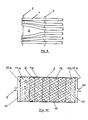
- FIG. 5 shows the hollow fiber winding body according to FIG. 4 in cross section.
- a hollow fiber winding body designed in this way can be used to allow three media to participate in a mass and / or heat exchange at the same time.
- the medium A flows through the helically shaped hollow threads 1a, the medium B through the spiral shaped hollow threads 1b and the medium C around the hollow threads 1a and 1b, the direction of flow of which essentially runs transversely to the longitudinal axis of the hollow thread winding body.
- three hollow threads 1 are combined into groups at the left end of the hollow thread mat by a special arrangement of the inserted transverse threads 2 or the like, the distance between the hollow threads 1 from each other being smaller than the distance between the outer hollow threads within each group of the two adjacent hollow fiber groups shown from each other.
- the gap 3 formed by this type of arrangement of the hollow thread ends between the hollow thread groups allows a better penetration of the medium flowing around the hollow threads in the hollow fiber winding body.
- the transverse threads 2 or the like which are inserted further to the center of the hollow threads 1 are arranged in such a way that they keep the hollow threads 1 at a mutually substantially equal distance.
- FIG. 7 shows a particularly preferred embodiment of the method for producing the hollow fiber winding body.
- the mode of operation of the method is illustrated by the section A - A and B - B, part of the ends of the hollow fibers being designated a, b etc. to m and the other ends of the hollow fibers in question 1 being designated a ⁇ , b ⁇ etc. to m ⁇ .
- the respective position of the hollow fiber ends can be seen both in the top view and in section A - A and B - B.
- a hollow thread mat is shown, which or the like through the hollow threads 1 and the inserted transverse threads 2. is formed and is wound spirally to the hollow fiber winding body 5, in which the hollow threads 1 are arranged helically.
- the hollow threads 1 are held at a mutual distance by the inserted transverse threads 2 or the like.
- the hollow threads 1 are aligned parallel to the axis of rotation, ie the longitudinal axis, of the hollow thread winding body 5, that is to say perpendicular to the direction of conveyance of the hollow thread mat indicated by the arrow 7.
- the hollow fiber mat is moved over the rollers 3, 4 and 6 at a constant speed onto the axis of rotation or the hollow fiber winding body 5.
- the hollow thread mat on the side with the hollow thread ends a to m experiences essentially no significant deflection on its way to the axis of rotation or to the hollow fiber winding body 5
- the oblique position of the hollow filaments 1 slightly reduces the width of the hollow filament mat.
- the procedure described above is facilitated if the connection between the hollow threads 1 and the inserted transverse threads 2 or the like. a change in the angular position to each other without kinking the hollow fibers at this point allows, ie if this connection is not angularly rigid.
- This also applies to the method shown in FIG. 8.
- the oblique position of the hollow threads 1 can be varied as desired immediately before the winding up by the extent of the deflection with the aid of the deflection roller 4. The stronger the deflection, the greater the lag of the hollow fiber ends a ⁇ , b ⁇ etc. on this side of the hollow fiber mat and the greater the inclination of the hollow threads 1, i.e.
- FIG. 7 also shows that an oblique position of the hollow filaments 1 which is mirror-inverted to the inclined position of the hollow filaments 1 can be achieved in that the deflecting roller 6 is brought into a position which corresponds to the represented position of the deflecting roller 4 and vice versa. This deflects that side of the hollow fiber mat on which the hollow thread ends a to m are located, but not the side on which the hollow thread ends a ⁇ to m ⁇ are located, so that the hollow thread ends a, b etc. to m relative to the hollow thread ends a ⁇ , b ⁇ etc. are lagging behind.
- two hollow thread mats can be assumed, for example, the hollow threads 1 of which are initially arranged as shown in FIG Oblique position that the side with the hollow fiber ends a, b, etc. is deflected in one hollow fiber mat and the side with the hollow fiber ends a ⁇ , b ⁇ etc. in the other hollow fiber mat.
- the two hollow fiber mats it is also possible to deflect the two hollow fiber mats on the same side, but to different degrees.
- FIG. 8 a further embodiment of the method is shown in a simplified schematic representation, in which the hollow fiber winding body 5 is produced from hollow fiber mats 1 with hollow threads 1 of oppositely helical configuration arranged in two spirally arranged layers.
- Each hollow thread mat consists of the hollow threads 1 and the inserted transverse threads 2 or the like.
- Each hollow fiber mat is transported in a plane parallel to the axis of rotation (longitudinal axis) of the hollow fiber winding body 5, the direction of transport indicated by the arrows 7 initially running obliquely to the axis of rotation of the hollow thread winding body 5.
- the hollow fiber mats are deflected so that the hollow fiber mats are finally transported perpendicular to the axis of rotation of the hollow fiber winding body 5.
- the deflection of the hollow fiber mats takes place in the respective plane in such a way that the hollow thread ends on one side of each hollow thread mat describe a larger and thus longer arc than the hollow thread ends on the other side of the hollow thread mats.
- the ends of the hollow fibers, which describe the outer and thus longer circular arc run after the ends of the hollow fibers, which describe the inner, i.e.
- the strength of the deflection of the hollow fiber mats allows the inclined position of the hollow fibers to be changed and a hollow fiber winding body with intersecting but helically shaped hollow threads can also be produced.
- FIG. 9 shows different embodiments of hollow fiber mats A - F, which according to the invention can be combined in any number, but at least two, and are wound spirally to produce the hollow fiber winding body.
- the hollow fiber mats A - F shown can be produced with the methods described above but also with the methods belonging to the prior art. A detailed description of these methods known per se for producing hollow fiber mats therefore appears to be unnecessary here.
- the axis of rotation of the hollow fiber winding body must run vertically in the image plane imagine, ie the transport of the hollow fiber mats takes place horizontally in the image plane from right to left towards the indicated axis of rotation (longitudinal axis) of the hollow fiber winding body.
- Each hollow fiber mat A - E consists of the hollow threads 1 and the inserted transverse threads 2 or the like, with which they form the respectively specified angle.
- hollow threads are formed (in opposite directions).
- straight threads are produced which are substantially parallel to the longitudinal axis of the hollow fiber winding body.
- spiral-shaped hollow threads result which are arranged in planes which run essentially perpendicular to the longitudinal axis of the hollow thread winding body.
- the hollow thread mats D and E are hollow thread mats in which the hollow threads 1 are closed on one side. The closed end of the hollow filaments 1 can be arranged on the outer circumference of the hollow filament winding body or inside the same.
- Example G in FIG. 9 results from a combination of the hollow thread mat A (hollow threads 1a) with the hollow thread mat B (hollow threads 1b).
- hollow thread mat A hollow threads 1a
- hollow thread mat B hollow threads 1b
- the winding of, for example, a hollow fiber mat D and E or F with the arrangement of the hollow fibers 1 shown would therefore not be according to the invention.
- a + B or C or D or E or F A + B + C or D or E or F A + B + A + B (possibly + A + B etc.)
- the advantage of the embodiments of the method for producing the hollow fiber winding body shown in FIGS. 7 and 8 is in particular that it is possible to use hollow fiber mats immediately after their manufacture, e.g. to process on a weaving or knitting machine to hollow fiber winding bodies, the formation of the hollow threads of the hollow thread winding body can also be changed quickly and easily without interrupting the method.
- FIG. 10 shows a device in which a hollow fiber winding body is arranged in the housing 8 with the fluid connections 9 and 10.
- the hollow fiber winding body has the hollow threads 1a and 1b, the end regions of which are embedded in the potting compound blocks 11a and 11b, the potting compound blocks 11a; 11b are connected to the housing 8 in a fluid-tight manner.
- the hollow fiber winding body also has the inserted transverse threads 1 or the like. on.
- the hollow threads 1a; 1b are porous, ie the jacket (the wall) of the hollow filaments 1a; 1b has continuous pores which are open inwards and outwards, so that a fluid or even a very specific fluid can pass through the pores.
- the end regions of the hollow threads 1a; 1b are thus in the sealing compound blocks 11a; 11b embedded that the hollow threads 1a end at the cut surface 12a of the potting compound block 11a and thus open into the chamber 13, while their other ends are embedded within the potting compound block 11b and thus closed.
- the hollow filaments 1b it is exactly the opposite, ie the hollow filaments 1b end at the cut surface 12b of the potting compound block 11b and thus open into the chamber 14, while their other ends are embedded and sealed within the potting compound block 11a.
- This device can thus be used in the manner of a two-stage dead-end filter (cascade filter) for filtering or for another type of material separation.
- the pores of the hollow threads 1a can also have different pore sizes than the pores of the hollow threads 1b.
- material separation is also possible with so-called dense hollow fiber membranes called nonporous.
- the fluid which is completely or partially freed from any substance, the so-called filtrate or permeate passes through the jacket (the wall) of the hollow threads 1a into the extracapillary space 15 and from there through the jacket (the wall) of the hollow threads 1b, from where the now twice-filtered fluid leaves the device again through the chamber 14 and the fluid connection 10 after a further material separation has taken place when it has passed through the wall of the hollow threads 1b.
- the hollow fiber winding body shown in FIG. 10 is obtainable, for example, by winding the hollow thread mat (s) with the hollow threads 1a and the hollow thread mat (s) with the hollow threads 1b laterally offset from one another, so that the ends of the hollow threads 1a on one side and the Project ends of the hollow threads 1b on the other side of the hollow thread winding body.
- After embedding the ends of the hollow fibers, for example in a hardenable sealing compound only so much of the two sealing compound blocks is removed after the sealing compound has hardened that only the hollow threads 1a are exposed on one side and only the hollow threads 1b are exposed on the other side, i.e. on the cut surface 12a and 12b open.
- the hollow filaments 1a are helical and the hollow filaments 1b are helically shaped in opposite directions.
- this is only one of the possible embodiments of the hollow filaments, also for this embodiment of the hollow filament winding body described here.
- the hollow fiber winding body according to FIG. 10 can also contain solid or hollow threads which interact with the fluid in the extracapillary space, for example a substance transfer from the fluid and / or into the fluid, a chemical and / or physical Change in the fluid or the like cause.
- porous hollow filaments 1a could cause blood plasma separation and plasma cleaning in the extracapillary space, the cleaned plasma then being able to be removed again by porous hollow filaments 1b.
- the threads which cause a reaction with the fluid in the extracapillary space can, however, also be hollow threads, for example, the two ends of which are closed, for example by the sealing compound blocks, and which are filled with a corresponding substance.
- FIG. 11 serves to illustrate the method for dimensioning or determining the ratio according to the invention of the mutual spacing of adjacent transverse threads 2 within each hollow fiber mat to the mutual spacing of adjacent hollow threads 1 within each hollow thread mat.
- the mutual distance between adjacent transverse threads 2 is denoted by K j , that of adjacent hollow threads 1 by a i .
- the adjacent distance has the index j + 1 or i + 1 etc. to j + m or i + n.
- the mutual distances between the transverse threads 2 and the hollow threads 1 need not be the same, ie K j need not be equal to K j + 1 etc. and a i need not be equal to a i + 1 etc.
- the distances that belong together are used.
- the spacing of the transverse threads 2 K j + 1 and the mutual spacing of the hollow threads 1 in the region of the transverse threads 2 at this point are therefore a i + 1 decisive for the calculation.
- the transverse threads 2 and the hollow threads 1 form a rectangle at the point of their smallest mutual distance, the shorter side a i + 1 and the longer side K j + 1 is long.
- the distance ratio here corresponds to the ratio of the side lengths of the respective rectangle formed by the transverse threads 2 and the hollow threads 1.
- the distance range is to be dimensioned differently, which is possible by simple tests. If the dimensions are correct within the range according to the invention, mutual contact of the hollow threads is avoided with the usual hollow threads suitable for heat and / or mass transfer.
- the processing of the hollow fiber winding body into a usable unit, in which the hollow thread ends are embedded in a sealing compound block, can be facilitated in that the open ends of the hollow threads are closed as soon as the hollow thread mats are wound up.
- This can be done for example by welding, gluing, but in particular by squeezing.
- the ends of the hollow threads of the hollow thread mats are passed before being wound up by squeezing rollers, which flatten the hollow thread ends and thereby compress them so strongly that permanent deformation or even welding of the jacket of the hollow threads in this area and thus a closure of the hollow fiber ends is achieved.
- the ends of the hollow thread can be tied or the like by tying with the help of warp threads specially introduced in this area. to be closed (tied).
- the winding of the hollow thread mats can be carried out on a core which remains in the hollow thread winding body.
- core that is removed after winding the hollow fiber mats into a hollow fiber winding body.
- the beginning and / or the end of the hollow thread mats can be cut off parallel to the axis of rotation and the resulting open hollow threads can then be closed or simultaneously closed, for example by so-called welding which cutting and closing of the hollow fiber ends takes place in one operation.
- This ensures that the beginning and / or the end of these hollow fiber mats runs parallel to the winding axis and is not cone-shaped.
- This can be of great advantage for the handling of the hollow fiber mats when winding up to a hollow thread winding body, but also when unwinding from a hollow thread winding body, and makes handling easier. Unwinding takes place, for example, when several smaller hollow fiber winding bodies or other hollow fiber structures are produced from a larger hollow fiber winding body.
- the transverse threads or the other means keeping the hollow threads at a mutual distance can also be formed by adhesive tapes, but in particular by polyurethane potting threads, which are formed, for example, by applying the polyurethane in a flowable state to and possibly between the hollow threads and then allowing it to harden . This can also be done immediately before winding.
- the same material is used for the core of the hollow fiber winding body as for the investment material, for example polyurethane, soft PVC and the like. This makes it easier to cut off or otherwise remove part of the casting compound for the purpose of exposing and opening the ends of the hollow fibers.
- the hollow threads of the hollow thread winding body can also be U-shaped and the hollow thread ends can consequently be embedded on one side.
- a hollow fiber winding body can be used, for example, as a dead-end filter if appropriate hollow fibers are used.
- each of the two ends of the hollow threads open into separate chambers and thus to allow the hollow threads to flow through from one end of the hollow thread to the other.
Landscapes
- Engineering & Computer Science (AREA)
- Chemical & Material Sciences (AREA)
- Textile Engineering (AREA)
- Mechanical Engineering (AREA)
- Chemical Kinetics & Catalysis (AREA)
- Composite Materials (AREA)
- Manufacturing & Machinery (AREA)
- Separation Using Semi-Permeable Membranes (AREA)
- Nonwoven Fabrics (AREA)
Abstract
Description
Die Erfindung betrifft einen mehrlagigen Hohlfadenwickelkörper, bei welchem zumindest ein Teil der Hohlfäden wendelförmig und/oder ein Teil der Hohlfäden spiralförmig ausgebildet ist, die Hohlfäden innerhalb jeder Hohlfadenlage in einem gegenseitigen Abstand angeordnet sind, die Hohlfäden benachbarter aufeinanderfolgender Hohlfadenlagen sich kreuzen, die Hohlfäden in Form von wenigstens zwei übereinandergelegten und dann spiralförmig aufgewickelten Hohlfadenmatten angeordnet sind, die Hohlfäden innerhalb jeder Hohlfadenmatte von mehreren eingelegten Querfäden oder dergleichen gehalten werden, wobei innerhalb jeder Hohlfadenmatte der gegenseitige Abstand der Querfäden oder dergleichen größer ist als der gegenseitige Abstand der Hohlfäden, und keiner der Hohlfäden eine Umlenkstelle aufweist, ein Verfahren zum Herstellen des Hohlfadenwickelkörpers sowie die Verwendung des Hohlfadenwickelkörpers.The invention relates to a multilayer hollow fiber winding body, in which at least some of the hollow fibers are helical and / or some of the hollow fibers are spiral, the hollow fibers are arranged at a mutual distance within each hollow fiber layer, the hollow fibers of adjacent successive hollow fiber layers cross, the hollow fibers in the form of at least two superimposed and then spirally wound hollow thread mats are arranged, the hollow threads are held within each hollow thread mat by a plurality of inserted transverse threads or the like, the mutual spacing of the transverse threads or the like being greater than the mutual spacing of the hollow threads or none of the hollow threads within each hollow thread mat has a deflection point, a method for producing the hollow fiber winding body and the use of the hollow thread winding body.
Es sind Hohlfadenwickelkörper bekannt, die durch Aufwickeln eines Hohlfadens zu einer Kreuzspule hergestellt werden. Diese Art der Herstellung ist sehr aufwendig und bietet nur begrenzte Ausgestaltungsmöglichkeiten der auf diese Weise herstellbaren Hohlfadenwickelkörper.Hollow thread winding bodies are known which are produced by winding a hollow thread into a cheese. This type of production is very complex and offers only limited design options for the hollow fiber winding bodies which can be produced in this way.
Es sind auch mehrlagige Hohlfadenwickelkörper aus einem spiralförmig aufgewickelten Gewebe oder Gewirke aus Hohlfäden bekannt. Bei dieser Art von Hohlfadenwickelkörpern kann es an den Überkreuzungspunkten zum Einknicken der Hohlfäden kommen. Zudem ist die Herstellung von Geweben und Gewirken aus Hohlfäden aufwendig.There are also multi-layer hollow fiber winding bodies made of a spiral wound fabric or knitted fabrics made of hollow threads known. With this type of hollow fiber winding bodies, the hollow fibers may buckle at the crossover points. In addition, the production of woven and knitted fabrics from hollow threads is complex.
Aus der EP B1 0 093 677 ist ein mehrlagiger Hohlfadenwickelkörper bekannt, der dadurch hergestellt werden kann, daß mehrere Schichten von übereinanderliegenden, sich überkreuzenden Hohlfäden spiralförmig aufgerollt werden. Die einzelnen Hohlfadenschichten dieses Wickelkörpers sind hernach also spiralförmig angeordnet, wobei die Hohlfäden nicht durch mehrere Querfäden gehalten sind. Durch das hierdurch bedingte Fehlen einer ausreichenden Quervermischung läßt der konvektive Wärme- bzw. Stofftransport im extrakapillären Raum bei diesem bekannten Hohlfadenwickelkörper sehr zu wünschen übrig. Außerdem hat sich in der Praxis gezeigt, daß die ursprünglich regelmäßige Anordnung der Hohlfäden bei der Weiterverarbeitung stark gestört wird, so daß sich im Hohlfadenwickelkörper durch das Verschieben und Aneinanderlegen von Hohlfäden Lücken bilden, die zur Kanalbildung führen. Das in dieser Patentschrift beschriebene Herstellungsverfahren ist zudem sehr aufwendig und bietet nur beschränkte Ausgestaltungsmöglichkeiten für den Hohlfadenwickelkörper. Außerdem weisen einige der Hohlfäden bei diesem bekannten Hohlfadenwickelkörper Umlenkstellen auf, die durch die Umkehr der Changierbewegung beim Bewickeln der polygonalen Trommel mit Hohlfäden am Trommelende entstehen. Hierdurch können die Hohlfäden an den Umlenkstellen beschädigt werden, d.h. undicht werden oder sogar brechen.From
Aus der DE-OS 23 00 312 ist ein Hohlfadenwickelkörper bekannt, bei dem auf einem Kern eine Mehrzahl von Schichten aus Hohlfäden übereinander angeordnet sind, wobei innerhalb jeder einzelnen Schicht einander benachbarte Hohlfäden im wesentlichen parallel zueinander verlaufen, während benachbarte Hohlfäden benachbarter aufeinanderfolgender Hohlfadenschichten sich jeweils unter einem Winkel kreuzen. Die Herstellung erfolgt durch Aufwickeln eines Hohlfadens auch über die Stirnflächen eines Kerns in mehreren Schichten, also nicht durch spiralförmiges Aufwickeln eines Hohlfadenflächengebildes. Diese Art der Herstellung eines Hohlfadenwickelkörpers ist sehr aufwendig und führt zu einem hohen Anteil an Abfall, da die auf den Stirnflächen des Kerns aufgewickelten Hohlfadenabschnitte verworfen werden müssen. Darüberhinaus führt das Fehlen von Querfäden od. dgl. nicht nur zu einer ungenügenden Quervermischung im extrakapillären Raum, sondern auch zu einem sehr ungeordneten Aufbau des Hohlfadenwickelkörpers, da die in der Regel sehr glatten Hohlfäden bereits während der Herstellung des Hohlfadenwickelkörpers verrutschen, was zu einem Aneinanderliegen einer sehr großen Anzahl von Hohlfäden oder Hohlfadenabschnitten führt, was einerseits Kanalbildung, andererseits das Abdecken eines großen Teils der für die Wärme- bzw. Stoffübertragung wirksamen Fläche zur Folge hat.From DE-OS 23 00 312 a hollow fiber winding body is known in which a plurality of layers of hollow threads are arranged one above the other on a core, adjacent hollow threads running essentially parallel to each other within each individual layer, while adjacent hollow threads of adjacent successive hollow thread layers are in each case cross at an angle. The production is carried out by winding a hollow thread over the end faces of a core in several layers, that is, not by spirally winding a hollow fiber sheet. This type of manufacture of a hollow fiber winding body is very complex and leads to a high proportion of waste, since the hollow fiber sections wound on the end faces of the core have to be discarded. In addition, the absence of transverse threads or the like not only leads to insufficient cross-mixing in the extracapillary space, but also to a very disorderly structure of the hollow fiber winding body, since the generally very smooth hollow threads already slip during the manufacture of the hollow thread winding body, which results in abutment leads to a very large number of hollow threads or hollow thread sections, which on the one hand results in channel formation and on the other hand covers a large part of the area effective for heat or mass transfer.
Aus der DD-PS 233 946 ist ein Hohlfasermembranapparat bekannt, der durch Anfertigen von Bahnen paraller Hohlfasern, vorzugsweise durch Vernähen, Aufwickeln der Bahnen zu einem Faserbündel und Ausbilden von Anschlüssen hergestellt wird, indem das Faserbündel aus wenigstens zwei Bahnen gewickelt wird, wobei die Hohlfasern benachbarter Bahnen in einem Winkel von 10° bis 80° zueinander angeordnet werden, was vorzugsweise dadurch erreicht wird, daß die Bahnen von den Rändern aus schiefwinklig verzogen werden. Der seitliche Abstand der Nähte ist dabei relativ groß, so daß auch bei diesem bekannten Hohlfasermembranapparat benachbarte Hohlfasern nach dem Aufwickeln der Bahnen zu einem Faserbündel einander berühren, was zur Kanalbildung und Abdeckung von Membranfläche und demzufolge zu einer Verschlechterung der Wärme- und/oder Stoffübertragung führt.From DD-PS 233 946 a hollow fiber membrane apparatus is known which is produced by producing webs of parallel hollow fibers, preferably by sewing, winding the webs into a fiber bundle and forming connections by winding the fiber bundle from at least two webs, the hollow fibers Adjacent tracks are arranged at an angle of 10 ° to 80 ° to each other, which is preferred is achieved in that the sheets are warped from the edges at an oblique angle. The lateral spacing of the seams is relatively large, so that even in this known hollow fiber membrane apparatus, adjacent hollow fibers touch one another after winding the webs into a fiber bundle, which leads to channel formation and covering of the membrane surface and consequently to a deterioration in the heat and / or mass transfer .
Der vorliegenden Erfindung liegt daher die Aufgabe zugrunde, einen mehrlagigen Hohlfadenwickelkörper der eingangs beschriebenen Art zur Verfügung zu stellen, dessen Hohlfäden über ihre gesamte Länge in einem gegenseitigen seitlichen Abstand angeordnet sind und der deshalb einen verbesserten konvektiven Wärme- und/oder Stofftransport sowie eine erhöhte Wärme- und/oder Stoffübertragung gewährleistet, der größere Kombinations- und Ausgestaltungsmöglichkeiten hinsichtlich der Anordnung der Hohlfäden bietet und der auf einfache Weise herstellbar ist.The present invention is therefore based on the object of providing a multi-layer hollow fiber winding body of the type described at the outset, the hollow threads of which are arranged at a mutual lateral spacing over their entire length and which therefore has improved convective heat and / or mass transfer and increased heat - And / or material transfer guaranteed, which offers greater combination and design options with regard to the arrangement of the hollow fibers and which can be produced in a simple manner.
Diese Aufgabe wird durch einen Hohlfadenwickelkörper gelöst, der die kennzeichnenden Merkmale des Anspruchs 1 aufweist.This object is achieved by a hollow fiber winding body which has the characterizing features of
Es wurde namlich gefunden, daß nur dann, wenn das Verhältnis von gegenseitigem seitlichen Abstand benachbarter Querfäden innerhalb jeder Hohlfadenmatte zu gegenseitigem seitlichen Abstand benachbarter Hohlfäden innerhalb jeder Hohlfadenmatte in dem erfindungsgemäßen Bereich liegt, ein Anliegen benachbarter Hohlfäden mit Sicherheit vermieden wird, die Zwischenräume zwischen benachbarten Querfäden und benachbarten Hohlfäden dabei jedoch ausreichend groß sind, um ein gutes Durchströmen des Hohlfadenwickelkörpers bei ausreichend niedrigem Druckverlust zu gewährleisten. Bekanntlich können Hohlfäden, die vor der Verarbeitung zu einer Hohlfadenmatte zu einer Spule aufgespult waren, wellenförmig ausgebildet sein. Derartige Hohlfäden neigen besonders stark zu gegenseitiger Berührung, wenn sie zu einer Hohlfadenmatte verarbeitet werden und der seitliche Abstand der Querfäden zu groß gewählt wird. Dieser Umstand wurde bisher offenbar nicht beachtet, weshalb bei bekannten Hohlfadenmatten bzw. Hohlfadenwickelkörpern aus derartigen Matten der seitliche gegenseitige Abstand der Querfäden verhältnismäßig groß gewählt wurde.It was found, in particular, that only when the ratio of the mutual lateral spacing of adjacent transverse threads within each hollow fiber mat to the mutual lateral spacing of adjacent hollow threads within each hollow thread mat lies within the range according to the invention can the occurrence of adjacent hollow threads be avoided with certainty, the gaps between adjacent transverse threads and adjacent hollow fibers are, however, sufficiently large to ensure that there is sufficient flow through the hollow fiber winding body to ensure low pressure loss. As is known, hollow threads which were wound up into a bobbin prior to processing into a hollow thread mat can be designed in a wave shape. Hollow threads of this type are particularly susceptible to mutual contact if they are processed into a hollow thread mat and the lateral spacing of the transverse threads is chosen too large. This fact has apparently not been taken into account up to now, which is why, in known hollow fiber mats or hollow fiber winding bodies made of such mats, the lateral mutual distance of the transverse threads was chosen to be relatively large.
Unter gegenseitigem Abstand benachbarter Hohlfäden innerhalb jeder Hohlfadenmatte wird im Sinne der vorliegenden Erfindung der Abstand im unmittelbaren Bereich der Querfäden verstanden, da er in diesem Bereich im wesentlichen festgelegt ist.In the context of the present invention, the mutual spacing of adjacent hollow threads within each hollow thread mat is understood to mean the distance in the immediate area of the transverse threads, since it is essentially fixed in this area.
Der gegenseitige seitliche Abstand benachbarter Querfäden bzw. benachbarter Hohlfäden braucht innerhalb einer Hohlfadenmatte nicht gleich zu sein, solange jedes Abstandsverhältnis im erfindungsgemäßen Bereich liegt. Auch brauchen die gegenseitigen Abstände benachbarter Querfäden bzw. Hohlfäden der verschiedenen den Hohlfadenwickelkörper bildenden Hohlfadenmatten nicht gleich zu sein, also einander entsprechen.The mutual lateral spacing of adjacent transverse threads or adjacent hollow threads need not be the same within a hollow thread mat, as long as each spacing ratio is in the range according to the invention. Also, the mutual distances between adjacent transverse threads or hollow threads of the different hollow thread mats forming the hollow thread winding body need not be the same, that is to say they correspond to one another.
Zur Ermittlung des Abstandsverhältnisses wird der seitliche Abstand benachbarter Querfäden und benachbarter Hohlfäden natürlich in demselben Abschnitt der Hohlfadenmatte ermittelt. Die für eine Messung des Abstandsverhältnisses herangezogenen Querfäden und Hohlfäden bilden im wesentlichen ein Rechteck bzw. Parallelogramm und die seitlichen Abstände der Querfäden bzw. der Hohlfäden entsprechen den Abständen der gegnüberliegenden Seiten des von ihnen gebildeten Rechtecks bzw. Parallelogramms.To determine the distance ratio, the lateral distance between adjacent transverse threads and adjacent hollow threads is of course determined in the same section of the hollow thread mat. The transverse threads and hollow threads used for measuring the spacing ratio essentially form a rectangle or parallelogram and the lateral spacings of the transverse threads or the hollow threads correspond to the spacings of the opposite sides of the rectangle or parallelogram formed by them.
Der erfindungsgemäße Hohlfadenwickelkörper eignet sich zur Behandlung flüssiger, dampfförmiger und gasförmiger Medien.The hollow fiber winding body according to the invention is suitable for the treatment of liquid, vaporous and gaseous media.
Der erfindungsgemäße Hohlfadenwickelkörper kann einen mit Hohlfäden ausgefüllten Querschnitt oder einen ringförmigen Querschnitt mit einem zentralen axialen Strömungskanal oder einen ringförmigen Querschnitt mit einem den zentralen axialen Hohlraum ausfüllenden Kern (core) aufweisen. Dabei kann es sich um einen vollen Kern handeln, der den zentralen axialen Hohlraum völlig ausfüllt, oder aber um einen rohrförmigen, der den zentralen axialen Strömungskanal bildet. Der Hohlfadenwickelkörper kann im Querschnitt betrachtet auch flach ausgebildet sein. Ein solcher flacher Hohlfadenwickelkörper wird beispielsweise durch Aufwickeln von Hohlfadenmatten auf einen flach ausgebildeten (plattenförmigen) Kern erhalten. Der Querschnitt der Kerns hat dabei vorzugsweise die Form eines Rechtecks mit abgerundeten Ecken, eines Kreisabschnittes oder Halbkreises mit abgerundeten Kanten, einer Linse, einer Ellipse oder einer Sichel mit abgerundeten Kanten. Derartige Kernformen führen zu raumsparenden Hohlfadenwickelkörpern bzw. zu solchen, die beispielsweise der Körperoberfläche eines Patienten besser angepaßt sind. Bei rohrförmiger Ausgestaltung des Kerns, wobei dieser auch eine der zuvor genannten Querschnittsformen aufweisen kann, kann die Wand (der Mantel) des Kerns auch Durchbrüche aufweisen, um beispielsweise eine radiale Durchströmung des Hohlfadenwickelkörpers zu ermöglichen.The hollow fiber winding body according to the invention can have a cross section filled with hollow threads or an annular cross section with a central axial flow channel or an annular cross section with a core filling the central axial cavity. This can be a full core that completely fills the central axial cavity, or a tubular one that forms the central axial flow channel. Viewed in cross section, the hollow fiber winding body can also be flat. Such a flat hollow fiber winding body is obtained, for example, by winding hollow fiber mats onto a flat (plate-shaped) core. The cross section of the core is preferably in the form of a rectangle with rounded corners, a circular section or semicircle with rounded edges, a lens, an ellipse or a sickle with rounded edges. Such core shapes lead to space-saving hollow fiber winding bodies or to those which are better adapted, for example, to the body surface of a patient. In the case of a tubular configuration of the core, which can also have one of the aforementioned cross-sectional shapes, the wall (the jacket) of the core can also have openings, for example a radial one To allow flow through the hollow fiber winding body.
Wendelförmig bedeutet im Sinne der vorliegenden Erfindung "in Form einer in Bezug auf die Längsachse des Fadenwickelkörpers steilen Schraubenlinie, also in Form einer Schraubenlinie mit einem großen Steigungswinkel". Dies hat zur Folge, daß die Länge der so ausgebildeten Hohlfäden nicht wesentlich größer ist als die Länge des Hohlfadenwickelkörpers.For the purposes of the present invention, helical means "in the form of a helix which is steep with respect to the longitudinal axis of the thread winding body, ie in the form of a helix with a large pitch angle". The consequence of this is that the length of the hollow filaments thus formed is not substantially greater than the length of the hollow filament winding body.
Spiralförmig bedeutet im Sinne der vorliegenden Erfindung "in Form einer in einer im wesentlichen senkrecht zur Längsachse des Fadenwickelkörpers liegenden Ebene angeordneten Spirale". Dies hat zur Folge, daß je nach der Anzahl der Hohlfadenlagen und der Hohlfadenschichten und je nach der Länge des Hohlfadenwickelkörpers die spiralförmig ausgebildeten Hohlfäden auch eine von der Länge des Hohlfadenwickelkörpers wesentlich abweichende Länge aufweisen können.For the purposes of the present invention, spiral-shaped means "in the form of a spiral arranged in a plane lying essentially perpendicular to the longitudinal axis of the thread winding body". The consequence of this is that, depending on the number of hollow fiber layers and the hollow fiber layers and depending on the length of the hollow fiber winding body, the spirally formed hollow threads can also have a length which is substantially different from the length of the hollow fiber winding body.
Die Begriffe Hohlfadenlage und Hohlfadenmatte sind wie folgt zu verstehen: Unter Hohlfadenmatte wird eine flächige einlagige Anordnung von Hohlfäden verstanden, bei welcher die Hohlfäden durch faden- oder bandförmige oder ähnlich ausgebildete quer zu den Hohlfäden verlaufende Mittel gehalten werden. Unter Hohlfadenlage wird der bei der Herstellung des Hohlfadenwickelkörpers pro volle Umdrehung desselben aufgewickelte Abschnitt einer Fadenmatte verstanden. Wickelt man also beispielsweise zwei Hohlfadenmatten auf einen Kern, indem man diesen zehn volle Umdrehungen ausführen läßt, so erhält man einen Hohlfadenwickelkörper, der insgesamt zweimal zehn, also zwanzig Hohlfadenlagen aufweist.The terms hollow fiber layer and hollow thread mat are to be understood as follows: Hollow thread mat is understood to mean a flat single-layer arrangement of hollow threads, in which the hollow threads are held by means of thread-like or band-shaped or similarly designed means running transversely to the hollow threads. Hollow thread layer is understood to mean the section of a thread mat wound during the production of the hollow thread winding body per full revolution of the same. For example, if you wind two hollow fiber mats on a core by letting them make ten full revolutions, you get a hollow fiber winding body which has a total of two ten, ie twenty hollow fiber layers.
Unter Hohlfadenschicht wird eine aufgewicktelte Hohlfadenmatte verstanden.Hollow thread layer is understood to mean a wound hollow thread mat.
Innerhalb einer Hohlfadenschicht bzw. -matte müssen die Hohlfäden nicht unbedingt parallel zueinander angeordnet sein, obwohl dies in der Regel die zweckmäßigste Ausgestaltungsform sein dürfte.The hollow threads do not necessarily have to be arranged parallel to one another within a hollow thread layer or mat, although this is usually the most expedient embodiment.
Die die Hohlfäden in gegenseitigem Abstand haltenden Querfäden o. dgl. können beispielsweise durch ein Web- oder Wirkverfahren also beispielsweise als sogenannte Kett- oder Schußfäden eingebracht worden sein. Zur Verbesserung des konvektiven Wärme- bzw. Stofftransports sind die Hohlfäden und/oder die Querfäden vorzugsweise strukturiert und/oder profiliert. Werden beispielsweise textile Multifilamentfäden verwendet, so sind diese vorzugsweise texturiert. Die Querfäden sollten vorzugsweise verhältnismäßig locker um die Hohfäden geführt sein, um eine winkelsteife Verbindung bzw. ein Einschnüren der Hohlfäden durch die Querfäden zu vermeiden.The transverse threads or the like, which keep the hollow threads at a mutual distance, can be introduced, for example, by a weaving or knitting method, for example as so-called warp or weft threads. In order to improve the convective heat or material transport, the hollow threads and / or the transverse threads are preferably structured and / or profiled. If, for example, textile multifilament threads are used, these are preferably textured. The transverse threads should preferably be guided relatively loosely around the hollow threads in order to avoid an angularly rigid connection or constriction of the hollow threads by the transverse threads.
Die Hohlfäden benachbarter aufeinanderfogender Lagen des Hohlfadenwickelkörpers können auch gleichmäßig wendelförmig ausgebildet sein, weisen dann aber eine unterschiedliche Länge auf, auf Grund der Bedingung, daß sie sich kreuzen. In der Regel sind die Hohlfäden benachbarter aufeinanderfolgender Lagen jedoch gegensinnig wendelförmig oder abwechselnd wendelförmig und spiralförmig oder abwechselnd wendelförmig und geradlinig (achsparallel) oder abwechelnd spiralförmig und geradlinig (achsparallel) ausgebildet. Jedoch können auch drei oder mehr Schichten unter schiedlich ausgebildeter Hohlfäden abwechelnd, d.h. in aufeinanderfolgenden Lagen angeordnet sein, also beispielsweise abwechselnd wendelförmig, spiralförmig und geradlinig ausgebildete Hohlfäden oder abwechselnd zwei Lagen gegensinnig wendelförmig ausgebildeter Hohlfäden und eine Lage spiralförmig oder geradlinig ausgebildeter Hohlfäden. In jedem Fall aber kreuzen sich nur solche Hohlfäden, die nicht derselben Hohlfadenschicht angehören.The hollow filaments of adjacent layers of the hollow filament winding body can also be made uniformly helical, but then have a different length due to the condition that they intersect. As a rule, however, the hollow filaments of adjacent successive layers are designed in opposite helical or alternating helical and spiral or alternating helical and rectilinear (axially parallel) or alternately helical and rectilinear (axially parallel). However, three or more layers can also be under alternating hollow threads alternating, that is to be arranged in successive layers, for example, alternately helical, spiral and rectilinear hollow threads or alternating two layers of oppositely helical hollow threads and a layer of helical or rectilinear hollow threads. In any case, only those hollow threads that do not belong to the same hollow thread layer cross.
Der Hohlfadenwickelkörper kann Hohlfäden, die sich zur Wärmeübertragung und/oder Hohlfäden, die sich zur Stoffübertragung, zum Stoffaustausch und/oder zur Stofftrennung eignen, aufweisen. Hohlfäden, die sich hinsichtlich ihrer Eigenschaften und/oder ihrer Abmessungen und/oder ihrer Form unterscheiden, können auch zusammen in eine Hohlfadenwickelkörper angeordnet sein, so daß beispielsweise die Wärmeübertragung von einem Medium A auf ein Medium B durch hierfür geeignete Hohlfäden bewirkt werden kann, während gleichzeitig eine Stoffübertragung vom Medium B auf ein Medium C und/oder umgekehrt mit Hilfe hierfür geeigneter Hohlfäden stattfindet. Zur Stoffübertragung können auch mikroporöse Hohlfäden verwendet werden. Die Poren der Hohlfäden können zu diesem Zweck auch mit entsprechenden Substanzen gefüllt sein; auch kann das Hohlfadeninnere, also das Lumen, gefüllt sein.The hollow fiber winding body can have hollow threads which are suitable for heat transfer and / or hollow threads which are suitable for mass transfer, for mass transfer and / or for material separation. Hollow filaments, which differ in terms of their properties and / or their dimensions and / or their shape, can also be arranged together in a hollow filament winding body, so that, for example, the heat transfer from a medium A to a medium B can be effected by suitable hollow filaments, while at the same time a mass transfer from medium B to a medium C and / or vice versa takes place with the help of suitable hollow fibers. Microporous hollow fibers can also be used for mass transfer. For this purpose, the pores of the hollow threads can also be filled with appropriate substances; the interior of the hollow thread, ie the lumen, can also be filled.
Die Hohlfäden des Wickelkörpers können sich auch hinsichtlich ihrer Stofftransporteigenschaften unterscheiden, also beispielsweise für unterschiedliche Stoffe unterschiedliche Selektivitäten oder Semipermeabilitäten, aufweisen, hydrophil oder hydrophob sein, porös oder porenfrei sein usw.The hollow filaments of the winding body can also differ in terms of their mass transfer properties, that is to say, for example, have different selectivities or semipermeabilities for different substances, be hydrophilic or hydrophobic, be porous or non-porous, etc.
Unterschiede hinsichtlich der Form können beispielsweise darin bestehen, daß bei einem Teil der Hohlfäden die äußere Kontur, also der Umriß der Hohlfäden, im Querschnitt betrachtet im wesentlichen rund- bzw. kreisförmig ausgebildet ist und daß bei einem anderen Teil der Hohlfäden die äußere Kontur im Querschnitt betrachtet dreieckig, viereckig, dreilappig, vierlappig usw. ausgebildet ist.Differences in shape can, for example, consist in the fact that, in cross section, the outer contour, that is to say the outline of the hollow threads, is essentially circular or circular in cross section, and that in another part of the hollow threads, the outer contour in cross section considered triangular, quadrangular, three-lobed, four-lobed, etc.
Unterschiede können auch hinsichtlich der Hohlfadendurchmesser und der Hohlfadenlängen bestehen. Die Hohlfäden können auch unterschiedliche Lumenquerschnittsformen und/oder Wandstärken aufweisen.Differences can also exist with regard to the hollow thread diameter and the hollow thread length. The hollow filaments can also have different lumen cross-sectional shapes and / or wall thicknesses.
Der Hohlfadenwickelkörper ist daher zur Herstellung beispielsweise von Filtern, Oxygenatoren, Hämofiltern, Blutplasmaseparatoren, IV-Filtern, Crossflow-Mikrofiltern, Gasseparatoren, Membrandestillationseinrichtungen, Bioreaktoren, Adsorbern, Absorbern, Desorbern, Dialysatoren, Austauscherkolonnen, Füllkörpern für Füllkörperkolonnen, Controlled-Release-Einrichtungen, Einrichtungen zur (kontrollierten) langsamen Abgabe von Wirkstoffen, Duftstoffen u. dgl., usw. geeignet. Zu diesem Zweck kann der Hohlfadenwickelkörper, wie dies auch für die bekannten Hohlfadenwickelkörper aus dem Stand der Technik bekannt ist, in ein entsprechendes Gehäuse eingesetzt werden, welches die erforderlichen Anschlüsse für das Zu- und Abführen der an der Wärme- und/oder Stoffübertragung beteiligten Medien aufweist.The hollow fiber winding body is therefore for the production of, for example, filters, oxygenators, hemofilters, blood plasma separators, IV filters, crossflow microfilters, gas separators, membrane distillation devices, bioreactors, adsorbers, absorbers, desorbers, dialyzers, exchange columns, packed bodies for packed columns, control units, controllers Devices for the (controlled) slow release of active ingredients, fragrances and. Like., etc. suitable. For this purpose, the hollow fiber winding body, as is also known for the known hollow thread winding body from the prior art, can be inserted into a corresponding housing, which has the necessary connections for the supply and discharge of the media involved in the heat and / or mass transfer having.
Die beiden Endbereiche der Hohlfäden des erfindungsgemäßen Hohlfadenwickelkörpers können - wie dies auch bei den aus dem Stand der Technik bekannten Hohlfadenwickelkörpern und Hohlfadenbündeln üblich ist - in eine aushärtbare Vergußmasse eingebettet oder eingeschleudert werden. Durch Entfernen eines ausreichend langen Abschnitts der ausgehärteten Vergußmasse wird erreicht, daß die Hohlfäden mit ihren offenen Enden auf der Schnittfläche des dabei entstandenen sogenannten Rohrbodens münden. Der so ausgebildete Hohlfadenwickelkörper kann dann ähnlich einer Filterpatrone in ein Gehäuse mit Fluidanschlüssen eingesetzt werden. Das Eingießen der Hohlfadenendbereiche kann aber auch erst nach dem Einbringen des Hohlfadenwickelkörpers in ein Gehäuse mit Fluidanschlüssen erfolgen, so daß die Vergußmasse selbst die fluiddichte Abdichtung mit dem Gehäuse bewirkt. Auch dies ist aus dem Stand der Technik bekannt und braucht daher hier nicht weiter erläutert zu werden.The two end regions of the hollow filaments of the hollow filament winding body according to the invention can - as is also the case with the hollow filament winding bodies and hollow filament bundles known from the prior art - be embedded or thrown into a curable casting compound. By removing a sufficiently long section of the hardened casting compound, it is achieved that the hollow threads open with their open ends on the cut surface of the so-called tube sheet. The hollow fiber winding body formed in this way can then be inserted into a housing with fluid connections in a manner similar to a filter cartridge. However, the hollow fiber end regions can also be poured in only after the hollow fiber winding body has been introduced into a housing with fluid connections, so that the potting compound itself effects the fluid-tight seal with the housing. This is also known from the prior art and therefore need not be explained further here.
Bei Umströmung der Hohlfäden des Hohlfadenwickelkörpers in Längsrichtung desselben wird das betreffende Fluid häufig an einem Ende des Hohlfadenwickelkörpers im allgemeinen radial zugeführt und an seinem anderen Ende im allgemeinen auf der gegenüberliegenden Seite wieder radial abgeführt. Zur Vermeidung von Kanalbildung innerhalb des Hohlfadenwickelkörpers ist daher eine gleichmäßige Beaufschlagung aller Hohlfäden auch bereits im Bereich der Mediumzuführung wichtig. Um dies zu erreichen, sind die Hohlfäden des Hohlfadenwickelkörpers mit Vorteil insbesondere im Bereich der Mediumzuführung in wenigstens einer Hohlfadenschicht in Gruppen angeordnet, wobei in diesem Bereich der Abstand der Hohlfäden voneinander innerhalb einer Gruppe kleiner ist als der Abstand der äußeren Fäden benachbarter Faden gruppen. Vorzugsweise werden die Hohlfäden jedoch quer - also im wesentlichen senkrecht zu ihren Längsachsen - umströmt.When flowing around the hollow threads of the hollow thread winding body in the longitudinal direction thereof, the fluid in question is frequently supplied radially at one end of the hollow thread winding body and radially discharged again at its other end generally on the opposite side. In order to avoid channel formation within the hollow fiber winding body, it is therefore important that all hollow threads are acted upon evenly in the area of the medium feed. In order to achieve this, the hollow filaments of the hollow filament winding body are advantageously arranged in groups, in particular in the area of the medium feed in at least one hollow filament layer, in which area the spacing of the hollow filaments from one another within a group is smaller than the spacing of the outer threads of adjacent filaments groups. However, the hollow filaments are preferably flowed around transversely, ie essentially perpendicular to their longitudinal axes.
Bei Verwendung des Hohlfadenwickelkörpers mit Hohlfäden beispielsweise zur Gastrennung, zur Blutplasmagewinnung, zur Hämofiltration, zur Dead-End-Filtration, zur Entlüftung einer Flüssigkeit u. dgl. können die Hohlfäden wenigstens einer Hohlfadenschicht an einem Ende der Fadenschicht verschlossen sein.When using the hollow fiber winding body with hollow threads, for example for gas separation, for blood plasma extraction, for hemofiltration, for dead-end filtration, for venting a liquid and the like. Like. The hollow threads can be closed at least one hollow thread layer at one end of the thread layer.
Zur Vergleichmäßigung der Umströmung der Hohlfäden des Hohlfadenwickelkörpers mit einem Fluid kann zwischen wenigstens einem Teil der Hohlfadenlagen des Hohlfadenwickelkörpers ein fluiddurchlässiges mehr oder weniger steifes oder elastisches Flächengebilde angeordnet sein. Dieses kann zusätzlich so ausgebildet sein, daß es Substanzen, die in dem die Hohlfäden umströmenden Fluid enthalten sind, durch Absorption oder Adsorption aus dem Fluid entfernt. Hierzu eignen sich beispielsweise Fasern aus aktivem Kohlenstoff o. dgl.In order to equalize the flow around the hollow threads of the hollow thread winding body with a fluid, a fluid-permeable, more or less rigid or elastic flat structure can be arranged between at least part of the hollow thread layers of the hollow thread winding body. This can additionally be designed such that it removes substances contained in the fluid flowing around the hollow filaments from the fluid by absorption or adsorption. For example, fibers made of active carbon or the like are suitable for this.
Zum Herstellen des mehrlagigen Hohlfadenwickelkörpers werden erfindungsgemäß wenigstens zwei übereinandergelegte Hohlfadenmatten, bei denen die Hohlfäden innerhalb jeder Hohlfadenmatte in einem gegenseitigen Abstand zugeordnet sind und von mehreren eingelegten Querfäden o. dgl. gehalten werden, innerhalb jeder Hohlfadenmatte der gegenseitige Abstand der Querfäden o. dgl. größer ist als der gegenseitige Abstand der Hohlfäden, wobei das Verhältnis von gegenseitigem Abstand benachbarter Querfäden innerhalb jeder Hohlfadenmatte zu gegenseitigem Abstand benachbarter Hohlfäden innerhalb jeder Hohlfadenmatte im Bereich von 2 bis 40 liegt, und keiner der Hohlfäden eine Umlenkstelle aufweist, um eine Drehachse spiralförmig aufgewickelt, wobei die Hohlfäden benachbarter Hohlfadenmatten spätestens unmittelbar vor dem Aufwickeln in eine sich überkreuzende Anordnung gebracht werden.To produce the multi-layer hollow fiber winding body, according to the invention, at least two superimposed hollow fiber mats, in which the hollow threads are assigned at a mutual distance within each hollow thread mat and are held by a plurality of inserted cross threads or the like, the mutual distance between the transverse threads or the like is greater within each hollow thread mat is than the mutual Distance of the hollow threads, the ratio of the mutual distance of adjacent transverse threads within each hollow thread mat to the mutual distance of adjacent hollow threads within each hollow thread mat being in the range from 2 to 40, and none of the hollow threads having a deflection point spirally wound around an axis of rotation, the hollow threads of adjacent hollow thread mats be placed in a crossover arrangement at the latest immediately before winding.
Zum Herstellen des Hohlfadenwickelkörpers können auch unterschiedliche Hohlfäden verwendet werden, wobei auch innerhalb wenigstens einer Hohlfadenmatte unterschiedliche Hohlfäden angeordnet sein können. Unterschiedlich bedeutet, wie oben bereits ausführlich dargelegt, unterschiedlich hinsichtlich ihrer Abmessungen, ihrer Form, ihres Werkstoffes, ihrer Eigenschaften, ihrer Funktion usw.Different hollow threads can also be used to produce the hollow thread winding body, wherein different hollow threads can also be arranged within at least one hollow thread mat. Different, as already explained in detail above, means different with regard to their dimensions, their shape, their material, their properties, their function, etc.
Zusammen mit den Hohlfadenmatten kann wenigstens ein fluiddurchlässiges Flächengebilde, also beispielsweise ein Vlies, ein Gewebe, ein Gewirke, ein Schaumstoff usw., aufgewickelt werden. Es können aber auch genauso viele, ggf. auch unterschiedliche, Flächengebilde wie Hohlfadenmatten aufgewickelt werden, so daß im fertigen Hohlfadenwickelkörper zwischen jeder Hohlfadenlage eine Lage fluiddurchlässiges Flächengebilde angeordnet ist. Dieses kann - wie oben bereits ausgeführt - ad - oder absorptive Eigenschaften aufweisen.At least one fluid-permeable sheet, for example a fleece, a woven fabric, a knitted fabric, a foam, etc., can be wound up together with the hollow thread mats. However, it is also possible to wind up as many, possibly also different, flat structures such as hollow thread mats, so that a layer of fluid-permeable flat structure is arranged between each hollow thread layer in the finished hollow thread winding body. As already stated above, this can have ad- or absorptive properties.
Die Hohlfadenmatten können auf einer Webmaschine oder auf einer Wirkmaschine hergestellt werden, wobei die die Hohlfäden in einem gegenseitigen Abstand haltenden Querfäden als Schuß- bzw. als Kettfäden eingebracht werden können. Natürlich ist es auch möglich, andere, beispielsweise band- oder streifenförmige, Mittel zum Halten der Hohlfäden zu verwenden. Diese können ebenfalls wie Schuß- oder Kettfäden bei einem Gewebe bzw. Gewirke oder aber einseitig, d.h. jeweils nur auf einer Seite der Hohlfadenmatte, angeordnet sein. Diese können zudem als Abstandshalter zwischen benachbarten Hohlfadenlagen wirken.The hollow thread mats can be produced on a weaving machine or on a knitting machine, wherein the cross threads holding the hollow threads at a mutual distance can be introduced as weft or warp threads. Of course, it is also possible to use other means, for example in the form of strips or strips, for holding the hollow threads. These can also be like weft or warp threads in a woven or knitted fabric or one-sided, i.e. only be arranged on one side of the hollow fiber mat. These can also act as spacers between adjacent hollow fiber layers.
Die Verwendung von Querfäden wird dabei jedoch bevorzugt, da hierbei die Verbindung zwischen den eingelegten Querfäden und den Hohlfäden verhältnismäßig locker, d.h. nicht winkelsteif, ist, so daß die Winkellage der Hohlfäden und der eingelegten Querfäden zueinander, also der Kreuzungswinkel zwischen beiden, leicht veränderbar ist. Dies ermöglicht eine äußerst vorteilhafte Herstellung des Hohlfadenwickelkörpers und vielfältiger Ausgestaltungsmöglichkeiten desselben selbst dann, wenn von einer Hohlfadenmatte ausgegangen wird, bei welcher sich die Hohlfäden und die eingelegten Querfäden im wesentlichen rechtwinklig kreuzen und bei welcher die Längsachse jedes Hohlfadens zunächst im wesentlichen senkrecht zur Transportrichtung der Hohlfadenmatte vor dem Aufwickeln und parallel zur Drehachse des Hohlfadenwickelkörpers angeordnet ist, wie dies weiter unten noch ausführlicher beschrieben und erläutert wird.The use of transverse threads is preferred, however, since the connection between the inserted transverse threads and the hollow threads is relatively loose, ie not angularly rigid, so that the angular position of the hollow threads and the inserted transverse threads relative to one another, that is to say the crossing angle between the two, can be easily changed . This enables an extremely advantageous production of the hollow fiber winding body and a wide range of possible configurations even if a hollow thread mat is assumed, in which the hollow threads and the inserted transverse threads essentially cross at right angles and in which the longitudinal axis of each hollow thread is initially essentially perpendicular to the transport direction of the hollow thread mat is arranged before winding and parallel to the axis of rotation of the hollow fiber winding body, as will be described and explained in more detail below.
Innerhalb der Hohlfadenmatten können auch Vollfäden und Hohlfäden, und zwar in regelmäßigen, aber auch in unregelmäßigen Abständen voneinander angeordnet sein, falls sich dies bei der Herstellung der Hohlfadenmatten oder des Hohlfadenwickelkörpers oder bei dessen Gebrauch als vorteilhaft erweisen sollte. Ein Teil der Vollfäden kann aber auch nur eine rein mechanische Funktion erfüllen, also beispielsweise dem Hohlfadenwickelkörper eine größere Formstabilität verleihen.Solid threads and hollow threads can also be arranged within the hollow fiber mats, at regular, but also at irregular intervals, if this should prove to be advantageous in the manufacture of the hollow thread mats or the hollow fiber winding body or in the use thereof. However, some of the full threads can also only perform a purely mechanical function, for example giving the hollow fiber winding body greater dimensional stability.
Zum Herstellen des Hohlfadenwickelkörpers wird für jede Schicht mit wendelförmig auszubildenden Hohlfäden in besonders vorteilhafter Weise von einer Hohlfadenmatte mit parallel zueinander angeordneten Hohlfäden ausgegangen, bei der die Längsachse jedes Hohlfadens zunächst im wesentlichen senkrecht zur Transportrichtung der Hohlfadenmatte vor dem Aufwickeln ausgerichtet ist. Wird nun eine Seite der Hohlfadenmatte iber eine längere Transportwegstrecke geführt als die andere Seite der Hohlfadenmatte, so eilen die Hohlfadenenden auf dieser einen Seite der Hohlfadenmatte den Fadenenden auf der anderen Seite der Hohlfadenmatte nach, was zur Folge hat, daß die Hohlfäden in Bezug auf ihre Ausgangslage in eine Schräglage gebracht werden, d.h. in Bezug auf die Transportrichtung einen Winkel bilden, der größer bzw. kleiner als 90° ist. Werden die Hohlfäden unmittelbar vor dem Aufwickeln auf diese Weise auch in Bezug auf die Drehachse des Hohlfadenwickelkörpers in eine Schräglage gebracht, so daß sie mit der Drehachse also einen Winkel bilden, so führt dies zwangsläufig zu einer wendelförmigen Ausbildung der betreffenden Hohlfäden beim Aufwickeln derselben z.B. auf einen Kern oder den im Entstehen befindlichen Hohlfadenwickelkörper. Beispielsweise kann jede dieser Hohlfadenmatten vor dem Aufwickeln zunächst in einer zur Drehachse des Hohlfadenwickelkörpers parallelen Ebene transportiert werden, wobei die Transportrichtung jedoch parallel oder schräg, also nicht senkrecht, zur Drehachse des Hohlfadenwickelkörpers verläuft. Um den Transport der Hohlfadenmatte schließlich senkrecht auf die Drehachse des Hohlfadenwickelkörpers hin erfolgen zu lassen, muß die Hohlfadenmatte umgelenkt werden. Erfolgt die Umlenkung der Hohlfadenmatte vor dem Aufwickeln dabei in derselben Ebene derart, daß die Hohlfadenenden auf der einen Seite der Hohlfadenmatte einen Kreisbogen mit einem größeren Radius beschreiben als die Hohlfadenenden auf der anderen Seite der Hohlfadenmatte, so eilen die Hohlfadenenden auf dem größeren, d.h. längeren, Kreisbogen den Hohlfadenenden auf dem kleineren, d.h. kürzeren Kreisbogen nach, so daß die Hohlfäden auf diese Weise in eine Schräglage zur Drehachse des Hohlfadenwickelkörpers gebracht werden.To produce the hollow fiber winding body, a hollow thread mat with hollow threads arranged parallel to one another is used in a particularly advantageous manner for each layer with helical hollow threads, in which the longitudinal axis of each hollow thread is initially oriented essentially perpendicular to the direction of transport of the hollow thread mat before winding. If one side of the hollow thread mat is now guided over a longer transport path than the other side of the hollow thread mat, the hollow thread ends on this one side of the hollow thread mat hurry after the thread ends on the other side of the hollow thread mat, with the result that the hollow threads with respect to their Starting position be brought into an inclined position, ie form an angle with respect to the direction of transport that is greater or less than 90 °. If the hollow filaments are brought into an inclined position immediately before the winding in relation to the axis of rotation of the hollow fiber winding body, so that they form an angle with the axis of rotation, this inevitably leads to a helical formation of the hollow fibers in question Winding them up, for example, on a core or the hollow fiber winding body that is being created. For example, each of these hollow fiber mats can first be transported in a plane parallel to the axis of rotation of the hollow fiber winding body, but the direction of transport is parallel or oblique, that is, not perpendicular, to the axis of rotation of the hollow thread winding body. In order to finally allow the hollow fiber mat to be transported perpendicularly to the axis of rotation of the hollow fiber winding body, the hollow fiber mat must be deflected. If the hollow fiber mat is deflected before winding in the same plane in such a way that the hollow thread ends on one side of the hollow thread mat describe an arc with a larger radius than the hollow thread ends on the other side of the hollow thread mat, the hollow thread ends rush on the larger, ie longer , Circular arc after the hollow fiber ends on the smaller, ie shorter circular arc, so that the hollow fibers are brought into an inclined position to the axis of rotation of the hollow fiber winding body in this way.
Eine weitere, besonders bevorzugte Herstellungsmethode besteht darin, jede für wendelförmig auszubildende Hohlfäden bestimmte Hohlfadenmatte zunächst mit parallel zueinander und zur Drehachse des Hohlfadenwickelkörpers ausgerichteten Hohlfäden senkrecht zu deren Längsachse und somit senkrecht zur Drehachse des Hohlfadenwickelkörpers in einer zu dieser parallelen Ebene auf die Drehachse zuzubewegen. Lenkt man eine Seite der Hohlfadenmatte dabei kurz vor dem Aufwickeln im wesentlichen senkrecht zu der Ebene aus, in welcher die Hohlfadenmatte an sich transportiert wird, beispielsweise durch eine Auslenkrolle, so ist der Transportweg der Hohlfadenenden, die über die Auslenkrolle laufen, größer als der der Hohlfadenenden auf der anderen Seite der Hohlfadenmatte, die die Transportebene nicht verlassen. Durch diese Auslenkung wird bewirkt, daß die ausgelenkten Hohlfadenenden den anderen Hohlfadenenden nacheilen, so daß die Hohlfäden in eine Schräglage, d.h. in eine nicht parallele Lage, in Bezug auf die Drehachse des Hohlfadenwickelkörpers gebracht werden.A further, particularly preferred production method consists in moving each hollow fiber mat intended for helical hollow fibers with hollow fibers aligned parallel to one another and to the axis of rotation of the hollow fiber winding body perpendicular to their longitudinal axis and thus perpendicular to the axis of rotation of the hollow fiber winding body in a plane parallel to this on the axis of rotation. If one directs one side of the hollow fiber mat shortly before winding it essentially perpendicular to the plane in which the hollow fiber mat is transported per se, for example by a deflecting roller, the transport path of the hollow thread ends that run over the deflecting roller is greater than that of the hollow thread ends on the other side of the hollow thread mat that do not leave the transport plane. This deflection causes the deflected hollow fiber ends to lag behind the other hollow thread ends, so that the hollow fibers are brought into an inclined position, ie into a non-parallel position, with respect to the axis of rotation of the hollow fiber winding body.
Bei Hohlfadenmatten mit nicht parallel zueinander angeordneten Hohlfäden kann auf diese Weise erreicht werden, daß Hohlfäden nach dem Aufwickeln im Hohlfadenwickelkörper eine unterschiedliche Ausbildung annehmen, also gleichsinnig aber unterschiedlich stark wendelförmig, gleichsinnig und/oder gegensinnig wendelförmig und geradlinig (achsparallel) oder gegensinnig wendelförmig ausgebildet sein können.In the case of hollow fiber mats with hollow threads not arranged parallel to one another, it can be achieved in this way that hollow threads take on a different design after being wound up in the hollow fiber winding body, that is to say they are designed in the same direction but with different degrees of helix, in the same direction and / or in the opposite direction helical and rectilinear (parallel to the axis) or in the opposite direction helically can.
Die Hohlfäden bestehen vorzugsweise aus einem schmelzspinnbaren Polymeren oder regenerierter Cellulose, wobei für den Einsatz des Hohlfadenwickelkörpers im medizinischen Bereich die Hohlfäden bevorzugt aus einem biokompatiblen Werkstoff bestehen.The hollow fibers preferably consist of a melt-spinnable polymer or regenerated cellulose, the hollow fibers preferably being made of a biocompatible material for use in the hollow fiber winding body in the medical field.
Die Querfäden o. dgl. bzw. die Vollfäden können ebenfalls aus einem Polymeren oder aus regenerierter Cellulose, aber z.B. auch ganz oder teilweise aus Aktivkohle bestehen. Auch kann die Oberfläche der Hohl-, Quer- oder Vollfäden mit Sorbentien belegt sein.The transverse threads or the like or the solid threads can likewise consist of a polymer or of regenerated cellulose, but also, for example, entirely or partially of activated carbon. The surface of the hollow, transverse or solid threads can also be covered with sorbents.
Die Erfindung wird nun anhand der Zeichnung näher erläutert. Es zeigt:
Figur 1 eine Ausführungsform des Hohlfadenwickelkörpers im Querschnitt,Figur 2bis 4 Ausgestaltungsformen des HohlfadenwickelkörpersFigur 6 eine besondere Hohlfadenanordnung,Figur 7 in vereinfachter schematischer Darstellungsweise eine bevorzugte Ausführungsform des Verfahrens zum Herstellen des Hohlfadenwickelkörpers,- Figur 8 in vereinfachter schematischer Darstellungsweise eine weitere Ausführungsform des Verfahrens zum Herstellen des Hohlfadenwickelkörpers,
Figur 9 verschiedene Ausgestaltungsformen von zum Herstellen des Hohlfadenwickelkörpers geeigneten Hohlfadenmatten,Figur 10 eine Vorrichtung mit einer Ausführungsform des Hohlfadenwickelkörpers.- Figur 11 erläutert die Bemessung des erfindungsgemäßen Bereiches.
- FIG. 1 shows an embodiment of the hollow fiber winding body in cross section,
- Figure 2 to 4 embodiments of the hollow fiber winding body
- FIG. 6 shows a special hollow thread arrangement,
- FIG. 7 shows a preferred embodiment of the method for producing the hollow fiber winding body in a simplified schematic representation,
- FIG. 8 shows, in a simplified schematic representation, a further embodiment of the method for producing the hollow fiber winding body,
- FIG. 9 shows various embodiments of hollow fiber mats suitable for producing the hollow fiber winding body,
- Figure 10 shows a device with an embodiment of the hollow fiber winding body.
- FIG. 11 explains the dimensioning of the area according to the invention.
In Figur 1 ist in vereinfachter schematischer Darstellungsweise der Aufbau eines mehrlagigen Hohlfadenwickelkörpers, im Querschnitt betrachtet, dargestellt. Der Hohlfadenwickelkörper besteht hierbei aus insgesamt zwei spiralförmig aufgewickelten Hohlfadenmatten 1a und 1b, wobei, wie durch die Linien 1ʹa und 1ʹb angedeutet, der Hohlfadenwickelkörper beliebig viele Hohlfadenlagen aufweisen kann. Zur Verdeutlichung des Aufbaus des Hohlfadenwickelkörpers sind die Hohlfäden 1b als schwarze Punkte gezeichnet. Die Hohlfäden 1a und 1b sind innerhalb der Schicht, der sie angehören, in einem gegenseitigen Abstand angeordnet und von eingelegten Querfäden (nicht dargestellt) gehalten. Die Hohlfäden 1a und/oder 1b sind wendelförmig ausgebildet. Die Hohlfäden 1a oder 1b können jedoch auch geradlinig, also achsparallel, ausgebildet sein. In jedem Fall kreuzen die Hohlfäden 1a die Hohlfäden 1b.In Figure 1, the structure of a multi-layer hollow fiber winding body, viewed in cross section, is shown in a simplified schematic representation. The hollow fiber winding body consists of a total of two spirally wound
Be der in Figur 2 dargestellten Ausführungsform des Hohlfadenwickelkörpers sind die Hohlfäden 1a wendelförmig ausgebildet, während die Hohlfäden 1b geradlinig ausgebildet und achsparallel angeordnet sind. Die Hohlfäden 1a bilden mit der Längsachse des Hohlfadenwickelkörpers den Winkel αa.In the embodiment of the hollow fiber winding body shown in FIG. 2, the
Bei der in Figur 3 dargestellten Ausführungsform des Hohlfadenwickelkörpers sind sowohl die Hohlfäden 1a als auch die Hohlfäden 1b wendelförmig, jedoch gegensinnig wendelförmig, ausgebildet. Die Hohlfäden 1a bilden mit der Längsachse des Hohlfadenwickelkörpers den Winkel αa der im Sinne der hier vorliegenden Erfindung als größer als 0 definiert ist, während die Hohlfäden 1b mit der Längsachse des Hohlfadenwickelkörpers den Winkel αb bilden, der definitionsgemäß kleiner als 0 ist, absolut betrachtet, jedoch genauso groß wie der Winkel αa sein kann.In the embodiment of the hollow fiber winding body shown in FIG. 3, both the
Bei der in Figur 4 dargestellten Ausführungsform des Hohlfadenwickelkörpers sind die Hohlfäden 1a wendelförmig und die Hohlfäden 1b spiralförmig ausgebildet. Der Aufbau des Hohlfadenwickelkörpers und die Ausgestaltung der Hohlfäden 1 a und 1b dieser Ausführungsform wird in Figur 5 verdeutlicht, die den Hohlfadenwickelkörper gemäß Figur 4 im Querschnitt zeigt. Wie in Figur 5 darüberhinaus durch die Pfeile A, B und C veranschaulicht wird, kann ein in dieser Weise ausgestalteter Hohlfadenwickelkörper dazu verwendet werden, drei Medien gleichzeitig an einem Stoff- und/oder Wärmeaustausch teilnehmen zu lassen. Dabei strömt das Medium A durch die wendelförmig ausgebildeten Hohlfäden 1a, das Medium B durch die spiralförmig ausgebildeten Hohlfäden 1b und das Medium C um die Hohlfäden 1a und 1b, wobei dessen Strömungsrichtung im wesentlichen quer zur Längsachse des Hohlfadenwickelkörpers verläuft.In the embodiment of the hollow fiber winding body shown in FIG. 4, the
Bei den in den Figuren 2 bis 5 gezeigten Hohlfadenwickelkörpern sind die eingelegten Querfäden o. dgl. mit der Positionszahl 2 gekennzeichnet.In the hollow fiber winding bodies shown in FIGS. 2 to 5, the inserted transverse threads or the like are marked with the
Bei der in Figur 6 dargestellten Hohlfadenmatte sind am linken Ende der Hohlfadenmatte jeweils drei Hohlfäden 1 durch besondere Anordnung der eingelegten Querfäden 2 o. dgl. zu Gruppen zusammengafaßt, wobei innerhalb jeder Gruppe der Abstand der Hohlfäden 1 voneinander kleiner ist als der Abstand der äußeren Hohlfäden der beiden dargestellten benachbarten Hohlfadengruppen voneinander. Die durch diese Art der Anordnung der Hohlfadenenden gebildete Lücke 3 zwischen den Hohlfadengruppen gestattet ein besseres Eindringen des die Hohlfäden umströmenden Mediums in den Hohlfadenwickelkörper. Die weiter zur Mitte der Hohlfäden 1 eingelegten Querfäden 2 o. dgl. sind so angeordnet, daß sie die Hohlfäden 1 in einem gegenseitigen im wesentlichen gleichen Abstand halten.In the hollow fiber mat shown in FIG. 6, three
In Figur 7 ist eine besonders bevorzugte Ausführungsform des Verfahrens zum Herstellen des Hohlfadenwickelkörpers dargestellt. Die Wirkungsweise des Verfahrens wird durch den Schnitt A - A und B - B verdeutlicht, wobei ein Teil der Hohlfadenenden mit a, b usw. bis m und die anderen Enden der betreffenden Hohlfäden 1 mit aʹ, bʹ usw. bis mʹ bezeichnet sind. Die jeweilige Lage der Hohlfadenenden ist sowohl in der Draufsicht als auch im Schnitt A - A und B - B zu sehen. Zur Vereinfachung ist nur eine Hohlfadenmatte dargestellt, die durch die Hohlfäden 1 und die eingelegten Querfäden 2 o.dgl. gebildet wird und spiralförmig zu dem Hohlfadenwickelkörper 5 aufgewickelt wird, in welchem die Hohlfäden 1 wendelförmig angeordnet sind. Die Hohlfäden 1 werden durch die eingelegten Querfäden 2 o. dgl. in einem gegenseitigen Abstand gehalten. Zunächst sind die Hohlfäden 1 parallel zur Drehachse, d.h. Längsachse, des Hohlfadenwickelkörpers 5, also senkrecht zu der durch den Pfeil 7 angedeuteten Förderrichtung der Hohlfadenmatte, ausgerichtet. Die Hohlfadenmatte wird dabei über die Rollen 3, 4 und 6 mit gleichbleibender Geschwindigkeit auf die Drehachse bzw. den Hohlfadenwickelkörper 5 zubewegt. Während die Hohlfadenmatte an der Seite mit den Hohlfadenenden a bis m im wesentlichen keine nennenswerte Auslenkung auf ihrem Weg zur Drehachse bzw. zum Hohlfadenwickelkörper 5 erfährt, wird die Hohlfadenmatte an der Seite mit den Hohlfadenenden aʹ bis mʹ über die Auslenkrolle 4 geführt, wodurch die Hohlfadenenden aʹ bis mʹ eine längere Wegstrecke zurücklegen, als die Hohlfadenenden a bis m, diesen dadurch nacheilen und somit in eine nicht parallele Lage in Bezug auf die Drehachse (= Längsachse) des Hohlfadenwickelkörpers 5 gebracht werden. Wie die Figur 7 weiter zeigt, wird durch die Schräglage der Hohlfäden 1 die Breite der Hohlfadenmatte geringfügig verringert. Die zuvor beschriebene Verfahrensweise wird erleichtert, wenn die Verbindung zwischen den Hohlfäden 1 und den eingelegten Querfäden 2 o.dgl. eine Veränderung der Winkellage zueinander ohne Knicken der Hohlfäden an dieser Stelle gestattet, d.h. wenn diese Verbindung nicht winkelsteif ist. Dies gilt auch für das in Figur 8 dargestellte Verfahren. Wie der Figur 7 darüberhinaus entnommen werden kann, läßt sich die Schräglage der Hohlfäden 1 unmittelbar vor dem Aufwickeln durch das Maß der Auslenkung mit Hilfe der Auslenkrolle 4 beliebig variieren. Je stärker namlich die Auslenkung ist, desto größer ist die Nacheilung der Hohlfadenenden aʹ, bʹ usw. auf dieser Seite der Hohlfadenmatte und desto stärker ist die Schräglage der Hohlfäden 1, d.h. desto größer ist der Winkel, den die Hohlfäden 1 mit der Längsachse (Drehachse) des Hohlfadenwickelkörpers 5 bilden. Die Darstellung in Figur 7 zeigt außerdem, daß auch eine zu der dargestellten Schräglage der Hohlfäden 1 spiegelbildliche Schräglage der Hohlfäden 1 dadurch erreicht werden kann, daß die Umlenkrolle 6 in eine Position gebracht wird, die der dargestellten Position der Umlenkrolle 4 entspricht und umgekehrt. Hierdurch wird diejenige Seite der Hohlfadenmatte, an welcher sich die Hohlfadenenden a bis m befinden, ausgelenkt, nicht dagegen die Seite, an welcher sich die Hohlfadenenden aʹ bis mʹ befinden, so daß die Hohlfadenenden a, b usw. bis m gegenüber den Hohlfadenenden aʹ, bʹ usw. bis mʹ eine Nacheilung erfahren.FIG. 7 shows a particularly preferred embodiment of the method for producing the hollow fiber winding body. The mode of operation of the method is illustrated by the section A - A and B - B, part of the ends of the hollow fibers being designated a, b etc. to m and the other ends of the hollow fibers in
Zur Herstellung eines Hohlfadenwickelkörpers mit in zwei spiralförmig aufgewickelten Hohlfadenmatten angeordneten gegensinnig wendelförmig ausgebildeten Hohlfäden kann somit beispielsweise von zwei Hohlfadenmatten ausgegangen werden, deren Hohlfäden 1 zunächst wie in Figur 7 dargestellt, parallel zur Drehachse des Hohlfadenwickelkörpers 5 angeordnet sind und deren Hohlfäden 1 in eine entgegengesetzt verlaufende Schräglage dadurch gebracht werden, daß bei der einen Hohlfadenmatte die Seite mit den Hohlfadenenden a, b usw. und bei der anderen Hohlfadenmatte die Seite mit den Hohlfadenenden aʹ, bʹ usw. ausgelenkt wird. Es ist bei dem geschilderten Beispiel jedoch auch möglich, die beiden Hohlfadenmatten auf derselben Seite, jedoch unterschiedlich stark auszulenken. Hierdurch wird erreicht, daß die Hohlfäden derjenigen Hohlfadenmatte, deren Seite stärker ausgelenkt wird, in eine stärkere Schräglage gebracht werden als die Hohlfäden der anderen Hohlfadenmatte und sich die Hohlfäden der beiden Hohlfadenmatten somit überkreuzen und im Hohlfadenwickelkörper gleichsinnig wendelförmig ausgebildet sind.For the production of a hollow fiber winding body with oppositely helical hollow threads arranged in two spirally wound hollow thread mats, two hollow thread mats can be assumed, for example, the
In Figur 8 ist in vereinfachter schematischer Darstellungsweise eine weitere Ausführungsform des Verfahrens dargestellt, bei welcher der Hohlfadenwickelkörper 5 mit in zwei spiralförmig angeordneten Schichten angeordneten gegensinnig wendelförmig ausgebildeten Hohlfäden 1 aus zwei Hohlfadenmatten hergestellt wird. Jede Hohlfadenmatte besteht aus den Hohlfäden 1 und den eingelegten Querfäden 2 o.dgl. Jede Hohlfadenmatte wird in einer zur Drehachse (Längsachse) des Hohlfadenwickelkörpers 5 parallelen Ebene transportiert, wobei die durch die Pfeile 7 angedeutete Transportrichtung zunächst schräg zur Drehachse des Hohlfadenwickelkörpers 5 verläuft. Unmittelbar vor dem Aufwickeln der Hohlfadenmatten werden diese umgelenkt, so daß der Transport der Hohlfadenmatten schließlich senkrecht auf die Drehachse des Hohlfadenwickelkörpers 5 hin erfolgt. Die Umlenkung der Hohlfadenmatten erfolgt in der jeweiligen Ebene derart, daß die Hohlfadenenden auf der einen Seite jeder Hohlfadenmatte einen größeren und damit längeren Kreisbogen beschreiben als die Hohlfadenenden auf der anderen Seite der Hohlfadenmatten. Die Hohlfadenenden, die den äußeren und damit längeren Kreisbogen beschreiben, eilen den Hohlfadenenden, die den inneren, also kürzeren Kreisbogen beschreiben, nach, so daß die Hohlfäden auf diese Weise in eine Schräglage zur Drehachse des Hohlfadenwickelkörpers 5 gebracht werden, und zwar ist die Schräglage der Hohlfäden der einen Hohlfadenmatte derjenigen der Hohlfäden der anderen Hohlfadenmatte entgegengesetzt. Auch bei dieser Ausführungsform des Verfahrens kann durch die Stärke der Umlenkung der Hohlfadenmatten die Schräglage der Hohlfäden verändert werden und kann auch ein Hohlfadenwickelkörper mit sich kreuzenden jedoch gleichsinnig wendelförmig ausgebildeten Hohlfäden hergestellt werden.In FIG. 8, a further embodiment of the method is shown in a simplified schematic representation, in which the hollow
In Figur 9 sind unterschiedliche Ausführungsformen von Hohlfadenmatten A - F dargestellt, die erfindungsgemäß in beliebiger Anzahl, mindestens jedoch zwei, kombiniert werden können und zur Herstellung des Hohlfadenwickelkörpers spiralförmig aufgewickelte werden. Die Herstellung der dargestellten Hohlfadenmatten A - F kann mit den zuvor beschriebenen Verfahren aber auch mit den zum Stand der Technik gehörenden Verfahren erfolgen. Eine ausführliche Beschreibung dieser an sich bekannten Verfahren zum Herstellen von Hohlfadenmatten erscheint daher hier entbehrlich. Die Drehachse des Hohlfadenwickelkörpers muß man sich hierbei wie angedeutet in der Bildebene senkrecht verlaufend vorstellen, d.h. der Transport der Hohlfadenmatten erfolgt in der Bildebene waagerecht von rechts nach links auf die angedeutete Drehachse (Längsachse) des Hohlfadenwickelkörpers zu. Jede Hohlfadenmatte A - E besteht aus den Hohlfäden 1 und den eingelegten Querfäden 2 o.dgl., mit denen sie den jeweils angegebenen Winkel bilden. Durch (gleichzeitiges) Aufwickeln der Hohlfadenmatten A und B ergeben sich (gegensinnig) wendelförmig ausgebildete Hohlfäden. Durch Aufwickeln der Hohlfadenmatte C ergeben sich geradlinig ausgebildete im wesentlichen parallel zur Längsachse des Hohlfadenwickelkörpers verlaufende Hohlfäden. Durch Aufwickeln der Hohlfadenmatten D bis F ergeben sich spiralförmig ausgebildete Hohlfäden, die in Ebenen angeordnet sind, die im wesentlichen senkrecht zur Längsachse des Hohlfadenwickelkörpers verlaufen. Bei den Hohlfadenmatten D und E handelt es sich um Hohlfadenmatten, bei denen die Hohlfäden 1 an einer Seite verschlossen sind. Das verschlossene Ende der Hohlfäden 1 kann am Außenumfang des Hohlfadenwickelkörpers oder im Innern desselben angeordnet sein.FIG. 9 shows different embodiments of hollow fiber mats A - F, which according to the invention can be combined in any number, but at least two, and are wound spirally to produce the hollow fiber winding body. The hollow fiber mats A - F shown can be produced with the methods described above but also with the methods belonging to the prior art. A detailed description of these methods known per se for producing hollow fiber mats therefore appears to be unnecessary here. As indicated, the axis of rotation of the hollow fiber winding body must run vertically in the image plane imagine, ie the transport of the hollow fiber mats takes place horizontally in the image plane from right to left towards the indicated axis of rotation (longitudinal axis) of the hollow fiber winding body. Each hollow fiber mat A - E consists of the
Das Beispiel G in Figur 9 ergibt sich bei einer Kombination der Hohlfadenmatte A (Hohlfäden 1a) mit der Hohlfadenmatte B (Hohlfäden 1b). Wie nachfolgend gezeigt wird, gibt es im Rahmen der vorliegenden Erfindung eine Vielzahl von Kombinationsmöglichkeiten, wobei lediglich darauf zu achten ist, daß die Hohlfäden zweier benachbarter Hohlfadenmatten bzw. Hohlfadenschichten so anzuordnen sind, daß sie sich überkreuzen. Das Aufwickeln beispielsweise von einer Hohlfadenmatte D und E oder F mit der dargestellten Anordnung der Hohlfäden 1 wäre demnach nicht erfindungsgemäß.Example G in FIG. 9 results from a combination of the hollow thread mat A (
Die nachfolgend beispielshalber aufgezählten Kombinationen sind nur als Beispiele gedacht, nicht als Einschränkung.The combinations listed below by way of example are only intended as examples, not as a limitation.
Mögliche Kombinationen der in Figur 9 dargestellten Hohlfadenmatten A bis F:
A + B oder C oder D oder E oder F
A + B + C oder D oder E oder F
A + B + A + B (ggf. + A + B usw.)
A + B + C + A + B + C (ggf. + A + B + C usw.)
B + C oder D oder E oder F
C + D oder E oder F
C + D + C + E (ggf. + C + D + C + E usw.)Possible combinations of the hollow fiber mats A to F shown in FIG. 9:
A + B or C or D or E or F
A + B + C or D or E or F
A + B + A + B (possibly + A + B etc.)
A + B + C + A + B + C (possibly + A + B + C etc.)
B + C or D or E or F
C + D or E or F
C + D + C + E (possibly + C + D + C + E etc.)
Der Vorteil der in den Figuren 7 und 8 dargestellten Ausführungsformen des Verfahrens zum Herstellen des Hohlfadenwickelkörpers besteht insbesondere darin, daß es hierbei möglich ist, Hohlfadenmatten unmittelbar nach ihrer Herstellung z.B. auf einer Web- oder Wirkmaschine zu Hohlfadenwickelkörpern zu verarbeiten, wobei die Ausbildung der Hohlfäden des Hohlfadenwickelkörpers dabei auch schnell und auf einfache Weise ohne Unterbrechung des Verfahrens verändert werden kann.The advantage of the embodiments of the method for producing the hollow fiber winding body shown in FIGS. 7 and 8 is in particular that it is possible to use hollow fiber mats immediately after their manufacture, e.g. to process on a weaving or knitting machine to hollow fiber winding bodies, the formation of the hollow threads of the hollow thread winding body can also be changed quickly and easily without interrupting the method.
Figur 10 zeigt eine Vorrichtung, bei welcher ein Hohlfadenwickelkörper in dem Gehäuse 8 mit den Fluidanschlüssen 9 und 10 angeordnet ist. Der Hohlfadenwickelkörper weist die Hohlfäden 1a und 1b auf, deren Endbereiche in den Vergußmasseblöcken 11a bzw. 11b eingebettet sind, wobei die Vergußmasseblöcke 11a; 11b mit dem Gehäuse 8 fluiddicht verbunden sind. Der Hohlfadenwickelkörper weist darüberhinaus die eingelegten Querfäden 1 od.dgl. auf. Die Hohlfäden 1a; 1b sind porös, d.h. der Mantel (die Wand) der Hohlfäden 1a; 1b weist durchgehende nach innen und außen offene Poren auf, so daß ein Fluid oder auch nur ein ganz bestimmtes Fluid durch die Poren hindurchtreten kann. Die Endbereiche der Hohlfäden 1a; 1b sind so in die Vergußmasseblöcke 11a; 11b eingebettet, daß die Hohlfäden 1a an der Schnittfläche 12a des Vergußmasseblocks 11a enden und somit in die Kammer 13 münden, während ihre anderen Enden innerhalb des Vergußmasseblockes 11b eingebettet und somit verschlossen sind. Bei den Hohlfäden 1b ist es genau umgekehrt, d.h. die Hohlfäden 1b enden an der Schnittfläche 12b des Vergußmasseblocks 11b und münden somit in die Kammer 14, während ihre anderen Enden innerhalb des Vergußmasseblocks 11a eingebettet und smit verschlossen sind. Diese Vorrichtung kann somit nach Art eines zweistufigen Dead-End-Filters (Kaskadenfilter) zum Filtrieren oder zu einer anderen Art der Stofftrennung verwendet werden. Die Poren der Hohlfäden 1a können zu diesem Zweck auch andere Porengrößen aufweisen als die Poren der Hohlfäden 1b. Eine Stofftrennung ist aber auch mit als nichtporös bezeichneten (sogenannten dichten) Hohlfadenmembranen möglich.FIG. 10 shows a device in which a hollow fiber winding body is arranged in the housing 8 with the
Läßt man ein Fluid beispielsweise durch den Fluidanschluß 9 in die Hohlfäden 1a strömen, so tritt das von irgendeinem Stoff ganz oder teilweise befreite Fluid, das sogenannte Filtrat oder Permeat, durch den Mantel (die Wand) der Hohlfäden 1a in den extrakapillären Raum 15 und von dort durch den Mantel (die Wand) der Hohlfäden 1b, von wo aus das nunmehr zweifach gefilterte Fluid durch die Kammer 14 und den Fluidanschluß 10 die Vorrichtung wieder verläßt, nachdem beim Durchtritt durch die Wand der Hohlfäden 1b eine weitere Stoffabtrennung erfolgt ist.If, for example, a fluid is allowed to flow through the
Der in Figur 10 dargestellte Hohlfadenwickelkörper ist beispielsweise dadurch erhältlich, daß man die Hohlfadenmatte(n) mit den Hohlfäden 1a und die Hohlfadenmatte(n) mit den Hohlfäden 1b seitlich versetzt zueinander aufwickelt, so daß die Enden der Hohlfäden 1a an der einen Seite und die Enden der Hohlfäden 1b an der anderen Seite des Hohlfadenwickelkörpers überstehen. Nach dem Einbetten der Hohlfadenenden, beispielsweise in eine aushärtbare Vergußmasse, wird nach dem Aushärten der Vergußmasse nur soviel der beiden Vergußmasseblöcke entfernt, daß auf der einen Seite nur die Hohlfäden 1a und auf der anderen Seite nur die Hohlfäden 1b freigelegt werden, also an der Schnittfläche 12a bzw. 12b münden.The hollow fiber winding body shown in FIG. 10 is obtainable, for example, by winding the hollow thread mat (s) with the
Bei der in Figur 10 dargestellten Ausführungsform des Hohlfadenwickelkörpers sind die Hohlfäden 1a wendelförmig und die Hohlfäden 1b im Vergleich zu diesen gegensinnig wendelförmig ausgebildet. Dies ist - wie sich aus dem oben Gesagten ergibt - jedoch nur eine der möglichen Ausgestaltungsformen der Hohlfäden auch für diese hier beschriebene Ausführungsform des Hohlfadenwickelkörpers.In the embodiment of the hollow filament winding body shown in FIG. 10, the
In weiterer vorteilhafter Ausgestaltung kann der Hohlfadenwickelkörper gemäß Figur 10 auch noch Voll- oder Hohlfäden enthalten, die mit dem Fluid im extrakapillären Raum in reaktive Wechselwirkung treten, also beispielsweise eine Stoffübertragung aus dem Fluid und/oder in das Fluid, eine chemische und/oder physikalische Veränderung des Fluids o.dgl. bewirken. So könnte beispielsweise durch poröse Hohlfäden 1a eine Blutplasmaseparation und im extrakapillären Raum eine Plasmareinigung bewirkt werden, wobei das gereinigte Plasma anschließend durch poröse Hohlfäden 1b wieder abgeführt werden kann. Bei den eine Reaktion mit dem Fluid im extrakapillären Raum bewirkenden Fäden kann es sich aber beispielsweise auch um Hohlfäden handeln, deren beide Enden verschlossen sind, z.B. durch die Vergußmasseblöcke, und die mit einer entsprechenden Substanz gefüllt sind.In a further advantageous embodiment, the hollow fiber winding body according to FIG. 10 can also contain solid or hollow threads which interact with the fluid in the extracapillary space, for example a substance transfer from the fluid and / or into the fluid, a chemical and / or physical Change in the fluid or the like cause. For example, porous
Figur 11 dient zur Verdeutlichung der Methode zur Bemessung bzw. Bestimmung des erfindungsgemäßen Verhältnisses von gegenseitigem Abstand benachbarter Querfäden 2 innerhalb jeder Hohlfadenmatte zu gegenseitigem Abstand benachbarter Hohlfäden 1 innerhalb jeder Hohlfadenmatte. Der gegenseitige Abstand benachbarter Querfäden 2 ist mit Kj, derjenige benachbarter Hohlfäden 1 mit ai bezeichnet. Der jeweils benachbarte Abstand trägt den Index j+1 bzw. i+1 usw. bis j+m bzw. i+n. Die gegenseitigen Abstände der Querfäden 2 bzw. der Hohlfäden 1 untereinander brauchen nicht gleich zu sein, d.h. Kj braucht nicht gleich Kj+1 usw. und ai braucht nicht gleich ai+1 usw. zu sein. Für die Bestimmung des Abstandsverhältnisses werden jedoch die jeweils zusammengehörenden Abstände herangezogen. So sind der Abstand der Querfäden 2 Kj+1 und der gegenseitige Abstand der Hohlfäden 1 im Bereich der Querfäden 2 an dieser Stelle also ai+1 für die Berechnung maßgebend.FIG. 11 serves to illustrate the method for dimensioning or determining the ratio according to the invention of the mutual spacing of adjacent
Bei der in Figur 11 dargestellten Konfiguration bilden die Querfäden 2 und die Hohlfäden 1 an der Stelle ihres geringsten gegenseitigen Abstandes ein Rechteck, dessen kürzere Seite ai+1 und dessen längere Seite Kj+1 lang ist. Das Abstandsverhältnis entspricht hierbei also dem Verhältnis der Seitenlängen des jeweiligen durch die Querfäden 2 und die Hohlfäden 1 gebildeten Rechtecks. Je nach Ausgestaltung, Wellung, Kräuselung usw. der Hohlfäden 1 ist der Abstandsbereich unterschiedlich zu bemessen, was durch einfache Versuche möglich ist. Bei richtiger Bemessung innerhalb des erfindungsgemäßen Bereichs wird bei den üblichen zur Wärme- und/oder Stoffübertragung geeigneten Hohlfäden eine gegenseitige Berührung der Hohlfäden mit Sicherheit vermieden.In the configuration shown in Figure 11, the
Die Verarbeitung des Hohlfadenwickelkörpers zu einer gebrauchsfähigen Einheit, bei welcher die Hohlfadenenden in einem Vergußmasseblock eingebettet sind, kann dadurch erleichtert werden, daß die offenen Enden der Hohlfäden bereits beim Aufwickeln der Hohlfadenmatten verschlossen werden. Dies kann beispielsweise durch Verschweißen, Verkleben, insbesondere aber durch Verquetschen erfolgen. Um diese zuletzt genannte Art des Verschließens der Hohlfadenenden zu erreichen, werden die Enden der Hohlfäden der Hohlfadenmatten vor dem Aufwickeln durch Quetschwalzen geführt, die die Hohlfadenenden flachdrücken und dabei so stark zusammenpressen, daß eine bleibende Verformung oder gar Verschweißung des Mantels der Hohlfäden in diesem Bereich und damit ein Verschluß der Hohlfadenenden erreicht wird. Auch können die Hohlfadenenden durch Abbinden mit Hilfe von in diesem Bereich speziell eingebrachten Kettfäden o.dgl. verschlossen (zugeschnürt) werden.The processing of the hollow fiber winding body into a usable unit, in which the hollow thread ends are embedded in a sealing compound block, can be facilitated in that the open ends of the hollow threads are closed as soon as the hollow thread mats are wound up. This can be done for example by welding, gluing, but in particular by squeezing. In order to achieve this last-mentioned type of closing of the hollow fiber ends, the ends of the hollow threads of the hollow thread mats are passed before being wound up by squeezing rollers, which flatten the hollow thread ends and thereby compress them so strongly that permanent deformation or even welding of the jacket of the hollow threads in this area and thus a closure of the hollow fiber ends is achieved. Also, the ends of the hollow thread can be tied or the like by tying with the help of warp threads specially introduced in this area. to be closed (tied).
Hierdurch wird beim Einbetten oder Einschleudern der Hohlfadenenden in eine aushärtbare Vergußmasse, wie beispielsweise Polyurethan, Silikon o. dgl., ein Eintreten der Vergußmasse in das Hohlfadeninnere (Lumen) verhindert, während das Eindringen der Vergußmasse zwischen die Hohlfäden, also in den extrakapillären Raum, begünstigt wird. Darüberhinaus kann das vor dem Einbetten bzw. Einschleudern der Hohlfadenenden in eine Vergußmasse üblicherweise notwendige Verschließen der Hohlfadenenden, beispielsweise durch Wachs (sogenanntes Abwachsen), hierdurch gespart werden.This prevents the casting compound from entering the hollow fiber interior (lumen) when the hollow fiber ends are embedded or thrown into a hardenable casting compound, such as polyurethane, silicone or the like, while the casting compound penetrates between the hollow threads, that is to say into the extracapillary space. is favored. In addition, the sealing of the hollow fiber ends, which is usually necessary before embedding or hurling the hollow fiber ends into a casting compound, for example by wax (so-called waxing), can thereby be saved.
Das Aufwickeln der Hohlfadenmatten kann - wie oben bereits ausgeführt - auf einen Kern erfolgen, der im Hohlfadenwickelkörper verbleibt. Es ist jedoch auch möglich, einen Kern zu verwenden, der nach dem Aufwickeln der Hohlfadenmatten zu einem Hohlfadenwickelkörper wieder entfernt wird.As already stated above, the winding of the hollow thread mats can be carried out on a core which remains in the hollow thread winding body. However, it is also possible to use one To use core that is removed after winding the hollow fiber mats into a hollow fiber winding body.
Bei der Verwendung von Hohlfadenmatten, deren Hohlfäden einen Winkel mit der Drehachse des Hohlfadenwickelkörpers bilden, kann der Anfang und/oder das Ende der Hohlfadenmatten parallel zur Drehachse abgeschnitten und können die dabei entstehenden offenen Hohlfäden anschließend oder gleichzeitig verschlossen werden, beispielsweise durch sogenanntes Abschweißen, bei welchem Schneiden und Verschließen der Hohlfadenenden in einem Arbeitsgang erfolgt. Hierdurch wird erreicht, daß der Anfang und/oder das Ende dieser Hohlfadenmatten parallel zur Wickelachse verläuft und nicht zipfelförmig ausgebildet ist. Dies kann für die Handhabung der Hohlfadenmatten beim Aufwickeln zu einem Hohlfadenwickelkörper, aber auch beim Abwickeln von einem Hohlfadenwickelkörper von großem Vorteil sein und die Handhabung erleichtern. Das Abwickeln erfolgt beispielsweise dann, wenn aus einem größeren Hohlfadenwickelkörper mehrere kleinere Hohlfadenwickelkörper oder andere Hohlfadengebilde hergestellt werden.When using hollow thread mats, the hollow threads of which form an angle with the axis of rotation of the hollow fiber winding body, the beginning and / or the end of the hollow thread mats can be cut off parallel to the axis of rotation and the resulting open hollow threads can then be closed or simultaneously closed, for example by so-called welding which cutting and closing of the hollow fiber ends takes place in one operation. This ensures that the beginning and / or the end of these hollow fiber mats runs parallel to the winding axis and is not cone-shaped. This can be of great advantage for the handling of the hollow fiber mats when winding up to a hollow thread winding body, but also when unwinding from a hollow thread winding body, and makes handling easier. Unwinding takes place, for example, when several smaller hollow fiber winding bodies or other hollow fiber structures are produced from a larger hollow fiber winding body.
Die Querfäden oder die anderen die Hohlfäden in einem gegenseitigen Abstand haltenden Mittel können auch durch Klebebänder, insbesondere aber durch Polyurethanvergußfäden gebildet werden, die beispielsweise dadurch gebildet werden, daß das Polyurethan in fließfähigem Zustand auf und ggf. zwischen die Hohlfäden aufgebracht und danach aushärten gelassen wird. Dies kann auch unmittelbar vor dem Aufwickeln erfolgen.The transverse threads or the other means keeping the hollow threads at a mutual distance can also be formed by adhesive tapes, but in particular by polyurethane potting threads, which are formed, for example, by applying the polyurethane in a flowable state to and possibly between the hollow threads and then allowing it to harden . This can also be done immediately before winding.
Einen großen Vorteil bedeutet es dariberhinaus, wenn für den Kern des Hohlfadenwickelkörpers derselbe Werkstoff wie für die Einbettmasse verwendet wird, beispielsweise Polyurethan, Weich-PVC u.dgl. Dies nämlich erleichtert das stirnseitige Abschneiden oder andersartige Abtragen eines Teils der Vergußmasse zum Zwecke des Freilegens und Öffnens der Hohlfadenenden.It is also a great advantage if the same material is used for the core of the hollow fiber winding body as for the investment material, for example polyurethane, soft PVC and the like. This makes it easier to cut off or otherwise remove part of the casting compound for the purpose of exposing and opening the ends of the hollow fibers.
Die Hohlfäden des Hohlfadenwickelkörpers können auch U-förmig ausgebildet und die Hohlfadenenden demzufolge einseitig eingebettet sein. Ein solcher Hohlfadenwickelkörper kann bei Verwendung entsprechender Hohlfäden beispielsweise als Dead-End-Filter eingesetzt werden. Es ist aber auch hierbei möglich, jedes der beiden Enden der Hohlfäden in getrennte Kammern münden zu lassen und somit ein Durchströmen der Hohlfäden von einem Hohlfadenende zum anderen zu ermöglichen.The hollow threads of the hollow thread winding body can also be U-shaped and the hollow thread ends can consequently be embedded on one side. Such a hollow fiber winding body can be used, for example, as a dead-end filter if appropriate hollow fibers are used. However, it is also possible here to have each of the two ends of the hollow threads open into separate chambers and thus to allow the hollow threads to flow through from one end of the hollow thread to the other.
Bei Verwendung von Vollfäden - wie oben bereits ausführlich beschrieben - können diese zusätzlich zu den Hohlfäden oder aber auch anstelle einzelner Hohlfäden eingebracht werden und können auch in die Hohlfadenmatten integriert werden.When using full threads - as already described in detail above - these can be introduced in addition to the hollow threads or instead of individual hollow threads and can also be integrated into the hollow thread mats.
Claims (26)
Applications Claiming Priority (4)
| Application Number | Priority Date | Filing Date | Title |
|---|---|---|---|
| DE3707584 | 1987-03-10 | ||
| DE3707584 | 1987-03-10 | ||
| DE3803693 | 1988-02-08 | ||
| DE19883803693 DE3803693A1 (en) | 1987-03-10 | 1988-02-08 | MULTI-LAYER HOLLOW FILM BODY |
Publications (3)
| Publication Number | Publication Date |
|---|---|
| EP0285812A1 true EP0285812A1 (en) | 1988-10-12 |
| EP0285812B1 EP0285812B1 (en) | 1993-10-06 |
| EP0285812B2 EP0285812B2 (en) | 1999-03-10 |
Family
ID=25853282
Family Applications (1)
| Application Number | Title | Priority Date | Filing Date |
|---|---|---|---|
| EP19880103317 Expired - Lifetime EP0285812B2 (en) | 1987-03-10 | 1988-03-03 | Multiple layer hollow fibre assembly |
Country Status (5)
| Country | Link |
|---|---|
| US (2) | US4940617A (en) |
| EP (1) | EP0285812B2 (en) |
| JP (1) | JP2941280B2 (en) |
| DE (2) | DE3803693A1 (en) |
| ES (1) | ES2044988T5 (en) |
Cited By (18)
| Publication number | Priority date | Publication date | Assignee | Title |
|---|---|---|---|---|
| DE4004797A1 (en) * | 1990-02-16 | 1991-08-22 | Akzo Gmbh | WOVEN HOLLOW STRAP |
| DE4322278A1 (en) * | 1993-07-05 | 1995-01-19 | Alfred Steinforth | Process for producing capillary membrane bundles |
| WO1997008933A2 (en) * | 1995-09-01 | 1997-03-13 | Baxter International Inc. | Hollow fiber oxygenator |
| WO1997019742A1 (en) * | 1995-11-30 | 1997-06-05 | Minnesota Mining And Manufacturing Company | Multilayer hollow fiber body and method of making |
| WO1998028064A1 (en) * | 1996-12-21 | 1998-07-02 | Akzo Nobel Nv | Membrane module with hollow fibre membranes arranged in layers |
| US6022478A (en) * | 1996-02-01 | 2000-02-08 | Akzo Nobel N.V. | Device and process for the substance-specific treatment of fluids |
| US6270674B1 (en) | 1997-06-14 | 2001-08-07 | Akzo Nobel Nv | Membrane module with unilaterally embedded hollow fiber membranes |
| WO2008083965A2 (en) * | 2007-01-13 | 2008-07-17 | Membrana Gmbh | Device for removing leukocytes from blood |
| US7429343B2 (en) | 2002-01-24 | 2008-09-30 | Membrana Gmbh | Process for producing polyolefin membrane with integrally asymmetrical structure |
| EP2055368A1 (en) | 2007-10-30 | 2009-05-06 | Membrana GmbH | Shell-less hollow fibre module |
| WO2010006815A3 (en) * | 2008-07-18 | 2010-10-14 | Donald Herbst | Heat exchanger, method for operating the heat exchanger and use of the heat exchanger in an air-conditioning system |
| WO2011107517A1 (en) * | 2010-03-03 | 2011-09-09 | Gambro Lundia Ab | Diffusion and/or filtration device |
| DE102010027973A1 (en) * | 2010-04-20 | 2011-10-20 | Ilias-Medical Gmbh | Method and device for producing a membrane mode |
| US8501008B2 (en) | 2005-09-09 | 2013-08-06 | Membrana Gmbh | Method for the elimination of leukocytes from blood |
| WO2017167443A3 (en) * | 2016-03-29 | 2017-11-16 | Enmodes Gmbh | Hollow-fibre membrane for mass transfer, and method of production |
| EP3473327A1 (en) | 2017-10-19 | 2019-04-24 | 3M Innovative Properties Company | Integrated fluid treatment device, and process using such device |
| CN109720913A (en) * | 2018-11-13 | 2019-05-07 | 北京苍轩文化传播有限公司 | A kind of winding device and winding method of tae kwon do ground cushion |
| WO2021219330A1 (en) | 2020-04-30 | 2021-11-04 | Enmodes Gmbh | Winding system for winding up concatenated hollow fibres onto a winding core |
Families Citing this family (89)
| Publication number | Priority date | Publication date | Assignee | Title |
|---|---|---|---|---|
| DE3803693A1 (en) * | 1987-03-10 | 1988-09-22 | Akzo Gmbh | MULTI-LAYER HOLLOW FILM BODY |
| US5236665A (en) * | 1988-10-20 | 1993-08-17 | Baxter International Inc. | Hollow fiber treatment apparatus and membrane oxygenator |
| DE3929473A1 (en) * | 1989-09-05 | 1991-03-07 | Ch Polt I | Angular winding of resin impregnated glass fabric - in which applicator trolley with roll of fabric moves sideways relative to rotating mandrel and has resin bath and fabric guides |
| JPH0817921B2 (en) * | 1989-12-12 | 1996-02-28 | 株式会社日立製作所 | Liquid / liquid contact device, and distillation device and gas exchange device using the same |
| US5224522A (en) * | 1990-02-16 | 1993-07-06 | Akzo N.V. | Manufacture of woven hollow fiber tape |
| DE4005132A1 (en) * | 1990-02-17 | 1991-08-22 | Akzo Gmbh | Hollow filament material stack - uses polygonal drum to wind layers for segments to be taken as a stack |
| CA2081206A1 (en) * | 1990-04-30 | 1991-10-31 | Wilfred F. Mathewson | Hollow fiber fluid treatment apparatus and membrane oxygenator |
| US5449457A (en) * | 1991-04-22 | 1995-09-12 | Hoechst Celanese Corporation | Liquid membrane modules with minimal effective membrane thickness and methods of making the same |
| US5169529A (en) * | 1991-04-22 | 1992-12-08 | Hoechst Celanese Corporation | Liquid membrane modules with minimal effective membrane thickness and methods of making the same |
| CA2065918A1 (en) * | 1991-04-22 | 1992-10-23 | Bradley W. Reed | Liquid membrane modules with minimal effective membrane thickness and methods of making the same |
| DE4129400A1 (en) * | 1991-09-04 | 1993-03-11 | Akzo Nv | METHOD FOR PRODUCING A HOLLOW FILM BODY |
| MX9206033A (en) * | 1991-10-22 | 1993-05-01 | Univ Brigham Young | IMPROVED CUSHIONING IN COMPOSITE STRUCTURES THROUGH EFFORT COUPLING. |
| US5264171A (en) * | 1991-12-31 | 1993-11-23 | Hoechst Celanese Corporation | Method of making spiral-wound hollow fiber membrane fabric cartridges and modules having flow-directing baffles |
| US5186832A (en) * | 1991-12-31 | 1993-02-16 | Hoechst Celanese Corporation | Spiral-wound hollow fiber membrane fabric cartridges and modules having integral turbulence promoters |
| TW223028B (en) * | 1991-12-31 | 1994-05-01 | Hoechst Celanese Corp | |
| US5269836A (en) * | 1992-08-28 | 1993-12-14 | Eastman Kodak Company | Passive inline membrane degasser and liquefier |
| US5557982A (en) * | 1992-09-21 | 1996-09-24 | Klein Bicycle Corporation | Composite bicycle handlebar |
| US5489413A (en) * | 1992-11-03 | 1996-02-06 | Cobe Laboratories, Inc. | Hollow fiber blood oxygenator |
| US5284584A (en) * | 1992-12-31 | 1994-02-08 | Hoechst Celanese Corporation | Hollow fiber membrane fabric - containing cartridges and modules having solvent-resistant thermoplastic tube sheets, and methods for making the same |
| US5312589A (en) * | 1993-03-04 | 1994-05-17 | Electromedics, Inc. | Gas transfer apparatus |
| US5514335A (en) * | 1993-10-25 | 1996-05-07 | Minnesota Mining And Manufacturing Company | Blood oxygenation system and reservoir and method of manufacture |
| US5429184A (en) * | 1994-03-28 | 1995-07-04 | Minntech Corporation | Wound heat exchanger oxygenator |
| IT1271104B (en) * | 1994-11-25 | 1997-05-26 | Dideco Spa | BLOOD OXYGENATOR WITH A LAYER OF MICROPOROUS MEMBRANE CAPILLARIES. |
| US6004511A (en) * | 1995-09-01 | 1999-12-21 | Baxter International Inc. | Hollow fiber oxygenator |
| US5762868A (en) * | 1995-11-30 | 1998-06-09 | Minnesota Mining And Manufacturing Company | Blood oxygenator and heat exchanger |
| US6013341A (en) * | 1996-08-19 | 2000-01-11 | Mcdonnell Douglas Corporation | Carrying (bearing) pipe-casing made of composite materials, the method and the setting (straightening device) for its manufacturing |
| US6148865A (en) * | 1996-12-02 | 2000-11-21 | A & P Technology, Inc. | Braided sleeve, tubular article and method of manufacturing the tubular article |
| US6250193B1 (en) | 1996-12-02 | 2001-06-26 | A & P Technology, Inc. | Braided structure with elastic bias strands |
| JP4791632B2 (en) | 1997-07-23 | 2011-10-12 | メムブラーナ ゲゼルシャフト ミット ベシュレンクテル ハフツング | Integrated asymmetric polyolefin membrane for gas exchange |
| US5968638A (en) * | 1997-08-04 | 1999-10-19 | Specialty Filaments, Inc. | Hollow filament with crimp for use in spiral binding |
| US6117390A (en) * | 1998-03-27 | 2000-09-12 | Medtronic, Inc. | Compact blood oxygenator utilizing longitudinally interspersed transversely extending heat exchanger conduits and oxygenator fibers |
| US6113782A (en) * | 1998-07-28 | 2000-09-05 | Terumo Cardiovascular Systems Corporation | Potting of tubular bundles in housing |
| JP4996011B2 (en) | 1999-01-21 | 2012-08-08 | メムブラーナ ゲゼルシャフト ミット ベシュレンクテル ハフツング | Integrated asymmetric polyolefin membrane |
| CN1136035C (en) | 1999-01-22 | 2004-01-28 | 制膜有限公司 | Method for producing an integrally asymmetrical polyolefin membrane |
| GB9902758D0 (en) * | 1999-02-08 | 1999-03-31 | H B Fuller Coatings Ltd | Heat transfer element |
| US6273355B1 (en) | 1999-05-06 | 2001-08-14 | Dideco S.P.A. | Method and apparatus for manufacturing wound tube bundles |
| US6165207A (en) * | 1999-05-27 | 2000-12-26 | Alsius Corporation | Method of selectively shaping hollow fibers of heat exchange catheter |
| US6508983B1 (en) | 1999-07-19 | 2003-01-21 | Cobe Cardiovascular | Exchanger apparatus and method of manufacture |
| US6613279B1 (en) * | 1999-08-31 | 2003-09-02 | Medtronic, Inc. | Method and apparatus for improving blood mixing in oxygenators |
| JP2003525736A (en) | 2000-03-07 | 2003-09-02 | エムアーテー アツォルプツィオーン テヒノロギース ゲゼルシャフト ミット ベシュレンクテル ハフツング ウント コンパニー コマンディートゲゼルシャフト | Module with membrane element with cross flow and dead end configuration |
| DE10011287A1 (en) * | 2000-03-08 | 2001-09-20 | Alcatel Sa | Optical receiver |
| US6432586B1 (en) | 2000-04-10 | 2002-08-13 | Celgard Inc. | Separator for a high energy rechargeable lithium battery |
| US6558450B2 (en) * | 2001-03-22 | 2003-05-06 | Celgard Inc. | Method for debubbling an ink |
| US6616841B2 (en) * | 2001-06-21 | 2003-09-09 | Celgard Inc. | Hollow fiber membrane contactor |
| US6776820B2 (en) | 2001-07-10 | 2004-08-17 | Praxair Technology, Inc. | Integral hollow fiber membrane gas dryer and filtration device |
| JP2003138354A (en) * | 2001-10-29 | 2003-05-14 | Mitsubishi Heavy Ind Ltd | Metal matrix composite |
| DE10242078A1 (en) * | 2002-09-09 | 2004-03-18 | Saxonia Bio Tec Gmbh | Fiber cassette, for processing a variety of fluids, comprises a number of fibers and/or hollow fibers anchored in the housing at one end and with open fibers at the other end, giving a variety of configurations for a modular structure |
| US7264725B2 (en) * | 2004-03-04 | 2007-09-04 | Celgard Inc. | Hollow fiber membrane contactor and method of making same |
| US7638049B2 (en) * | 2004-03-30 | 2009-12-29 | Celgard Inc. | Three-port high performance mini hollow fiber membrane contactor |
| US20060081524A1 (en) * | 2004-10-15 | 2006-04-20 | Amitava Sengupta | Membrane contactor and method of making the same |
| US8351490B2 (en) * | 2007-01-26 | 2013-01-08 | Agency For Science, Technology And Research | Radio frequency identification transceiver |
| WO2009003174A1 (en) * | 2007-06-27 | 2008-12-31 | Georgia Tech Research Corporation | Sorbent fiber compositions and methods of using the same |
| WO2009003171A1 (en) | 2007-06-27 | 2008-12-31 | Georgia Tech Research Corporation | Sorbent fiber compositions and methods of temperature swing adsorption |
| US7803274B2 (en) * | 2008-04-30 | 2010-09-28 | Celgard Llc | Contained liquid membrane contactor and a method of manufacturing the same |
| US8449706B2 (en) | 2008-05-30 | 2013-05-28 | Dic Corporation | Process for manufacturing deaerating hollow fiber module |
| US20100075074A1 (en) * | 2008-08-15 | 2010-03-25 | Wilson Erich A | Collapsible Mandrel Tools and Associated Methods for Fabrication of Wound Composite Articles |
| EP2335138A4 (en) * | 2008-08-15 | 2012-12-19 | Qualcomm Inc | Enhanced multi-touch detection |
| US9630141B2 (en) * | 2009-02-20 | 2017-04-25 | Cameron Solutions, Inc. | Membrane filter element with multiple fiber types |
| US8545754B2 (en) | 2009-04-23 | 2013-10-01 | Medtronic, Inc. | Radial design oxygenator with heat exchanger |
| CN102574061A (en) | 2009-09-30 | 2012-07-11 | 门布拉内有限公司 | Hollow fiber membrane mats with fluid impermeable segments and related methods |
| US20110239692A1 (en) * | 2010-04-01 | 2011-10-06 | Exxonmobil Research And Engineering Company | Utilization of waste heat using fiber sorbent system and method of using same |
| US8622950B2 (en) | 2010-05-03 | 2014-01-07 | Medtronic, Inc. | Rolled mat heat exchanger and method of manufacture |
| KR101985552B1 (en) | 2010-09-15 | 2019-06-03 | 비엘 테크놀러지스 인크. | Method to make a yarn-reinforced hollow fibre membranes around a soluble core |
| US8679606B2 (en) * | 2010-10-14 | 2014-03-25 | Vetco Gray Inc. | Thick walled composite tubular and method of making |
| US8529814B2 (en) | 2010-12-15 | 2013-09-10 | General Electric Company | Supported hollow fiber membrane |
| US8579845B2 (en) | 2011-01-27 | 2013-11-12 | Medtronic, Inc. | Wound heat exchanger |
| US8540081B2 (en) * | 2011-03-16 | 2013-09-24 | Markel Corporation | Fluoropolymer hollow fiber membrane with fluoro-copolymer and fluoro-terpolymer bonded end portion(s) and method to fabricate |
| US8685319B2 (en) * | 2011-04-29 | 2014-04-01 | Medtronic, Inc. | Combination oxygenator and arterial filter device with a fiber bundle of continuously wound hollow fibers for treating blood in an extracorporeal blood circuit |
| US8865067B2 (en) * | 2011-04-29 | 2014-10-21 | Medtronic, Inc. | Combination oxygenator and arterial filter device for treating blood in an extracorporeal blood circuit |
| US20130115267A1 (en) * | 2011-11-03 | 2013-05-09 | The Regents Of The University Of California | Compositions and methods for reducing edema |
| US9278317B2 (en) * | 2011-12-09 | 2016-03-08 | Lotte Chemical Corporation | Hollow fiber membrane module with miniskeins in miniheaders having a zig-zag configuration |
| US9321014B2 (en) | 2011-12-16 | 2016-04-26 | Bl Technologies, Inc. | Hollow fiber membrane with compatible reinforcements |
| US9022229B2 (en) | 2012-03-09 | 2015-05-05 | General Electric Company | Composite membrane with compatible support filaments |
| US8999454B2 (en) | 2012-03-22 | 2015-04-07 | General Electric Company | Device and process for producing a reinforced hollow fibre membrane |
| CN104703674B (en) | 2012-08-10 | 2017-08-15 | 宇部兴产株式会社 | Gas separation membrane module |
| JP6069944B2 (en) * | 2012-08-10 | 2017-02-01 | 宇部興産株式会社 | Gas separation membrane module |
| US9227362B2 (en) | 2012-08-23 | 2016-01-05 | General Electric Company | Braid welding |
| CA2895224A1 (en) | 2012-12-22 | 2014-06-26 | Dmf Medical Incorporated | An anesthetic circuit having a hollow fiber membrane |
| DE102014219960B4 (en) | 2014-10-01 | 2017-10-05 | Mahle International Gmbh | Method of manufacturing a humidifier block for a humidifier and humidifier |
| CN107000445B (en) * | 2014-12-24 | 2019-03-26 | Dic株式会社 | Doughnut degassing component and ink-jet printer |
| EP3100782A1 (en) | 2015-06-02 | 2016-12-07 | 3M Innovative Properties Company | Filter module with hollow cylinder housing |
| CN106039445B (en) * | 2016-08-17 | 2019-01-04 | 上海佩尼医疗科技发展有限公司 | A kind of superminiature dialyzer and its manufacturing method for clinical zooscopy |
| EP3482817A1 (en) | 2017-11-09 | 2019-05-15 | Frank Wiese | Membrane bundle presentation with spacers |
| KR102510133B1 (en) | 2017-11-09 | 2023-03-15 | 에보니크 오퍼레이션즈 게엠베하 | Membrane bundle layout having spacers |
| DE102019101740B4 (en) * | 2019-01-24 | 2021-08-05 | Dr. Ing. H.C. F. Porsche Aktiengesellschaft | Method for manufacturing a microchannel bundle heat exchanger |
| DE102020105454B4 (en) | 2020-03-02 | 2022-11-10 | Dr. Ing. H.C. F. Porsche Aktiengesellschaft | Method of manufacturing a microchannel bundle heat exchanger and using a microchannel bundle heat exchanger |
| US20230011904A1 (en) | 2021-07-12 | 2023-01-12 | Decarbontek LLC | Porous Solid Amine Adsorbents and Applications |
| TW202330078A (en) * | 2021-12-28 | 2023-08-01 | 日商Dic股份有限公司 | Degassing module and method for degassing liquid |
| DE102022125627B3 (en) | 2022-10-05 | 2024-02-01 | Dr. Ing. H.C. F. Porsche Aktiengesellschaft | Method for producing a woven heat exchanger |
Citations (2)
| Publication number | Priority date | Publication date | Assignee | Title |
|---|---|---|---|---|
| DE2721444A1 (en) * | 1977-05-12 | 1978-11-16 | Fresenius Chem Pharm Ind | HOLLOW FIBER DIALYZER |
| US4140637A (en) * | 1977-10-06 | 1979-02-20 | Walter Carl W | Permeability separatory method and apparatus |
Family Cites Families (25)
| Publication number | Priority date | Publication date | Assignee | Title |
|---|---|---|---|---|
| DE233946C (en) * | ||||
| DE207607C (en) * | ||||
| US2217370A (en) * | 1939-08-08 | 1940-10-08 | Socony Vacuum Oil Co Inc | Screen wrapped perforated liner pipe |
| US2215988A (en) * | 1939-10-05 | 1940-09-24 | Jean E Vivaudou | Covered sachet ball |
| US3422008A (en) * | 1963-10-24 | 1969-01-14 | Dow Chemical Co | Wound hollow fiber permeability apparatus and process of making the same |
| US3489647A (en) * | 1964-05-06 | 1970-01-13 | Dow Corning | Artificial organ for membrane dialysis of biological fluids |
| US3536611A (en) * | 1967-02-06 | 1970-10-27 | Abcor Inc | Membrane device and method |
| US3690465A (en) * | 1970-10-15 | 1972-09-12 | Du Pont | Permeation separation element |
| BE793624A (en) * | 1972-01-10 | 1973-05-02 | Baxter Laboratories Inc | DEVICE FOR THE TRANSFER OF MASSES, PRESENTING A WOUND TUBULAR DIFFISION MEMBRANE |
| GB1481064A (en) * | 1973-08-30 | 1977-07-27 | Teijin Ltd | Membrane apparatus for treating fluids |
| US4045851A (en) * | 1974-09-20 | 1977-09-06 | Albany International Corporation | Method of fabrication of hollow filament separatory module |
| CH614487A5 (en) * | 1977-02-27 | 1979-11-30 | Roland Frehner | |
| DE2825065A1 (en) * | 1978-06-08 | 1979-12-13 | Fresenius Chem Pharm Ind | Hollow fibre dialyser for artificial kidneys - with inlaid thicker thread forming splayed out bundle end |
| DE7911220U1 (en) * | 1979-04-18 | 1980-07-03 | Akzo Gmbh, 5600 Wuppertal | FILTER ELEMENT |
| FR2483901A1 (en) * | 1980-06-04 | 1981-12-11 | Hospal Sodip | PROCESS FOR OBTAINING HOLLOW FIBER BEAMS EMPTY AT THEIR ENDS |
| US4301013A (en) * | 1980-09-11 | 1981-11-17 | Abcor, Inc. | Spiral membrane module with controlled by-pass seal |
| DE3277363D1 (en) * | 1981-06-29 | 1987-10-29 | Baxter Travenol Lab | Microporous hollow fiber membrane assembly and its method of manufacture |
| FR2523727A1 (en) * | 1982-03-17 | 1983-09-23 | Lewiner Jacques | IMPROVEMENTS IN DEVICES FOR MEASURING ELECTRICAL LOADS CARRIED BY A DIELECTRIC |
| FR2525487B1 (en) * | 1982-04-27 | 1988-04-22 | Hospal Sodip | |
| DD207607A3 (en) * | 1982-05-28 | 1984-03-07 | Jens Finke | hollow fiber dialyzer |
| DE3236946C2 (en) * | 1982-10-06 | 1984-08-09 | Uranit GmbH, 5170 Jülich | Device for producing cross-wound layers for fiber-reinforced, rotationally symmetrical wound bodies |
| ZA8680B (en) * | 1985-01-08 | 1987-08-26 | Mcneilab Inc | Mass transfer device having a microporous,spirally wound hollow fiber membrane |
| DE3803693A1 (en) * | 1987-03-10 | 1988-09-22 | Akzo Gmbh | MULTI-LAYER HOLLOW FILM BODY |
| US5015379A (en) * | 1988-03-16 | 1991-05-14 | Mordeki Drori | Coiled filter strip with upstream and downstream butt ends |
| US4906372A (en) * | 1989-05-17 | 1990-03-06 | Desalination Systems, Inc. | Spiral-wound membrane cartridge |
-
1988
- 1988-02-08 DE DE19883803693 patent/DE3803693A1/en not_active Withdrawn
- 1988-03-03 EP EP19880103317 patent/EP0285812B2/en not_active Expired - Lifetime
- 1988-03-03 DE DE88103317T patent/DE3884650D1/en not_active Expired - Lifetime
- 1988-03-03 ES ES88103317T patent/ES2044988T5/en not_active Expired - Lifetime
- 1988-03-10 US US07/166,458 patent/US4940617A/en not_active Expired - Lifetime
- 1988-03-10 JP JP5510288A patent/JP2941280B2/en not_active Expired - Lifetime
-
1989
- 1989-12-07 US US07/447,417 patent/US5143312A/en not_active Expired - Lifetime
Patent Citations (2)
| Publication number | Priority date | Publication date | Assignee | Title |
|---|---|---|---|---|
| DE2721444A1 (en) * | 1977-05-12 | 1978-11-16 | Fresenius Chem Pharm Ind | HOLLOW FIBER DIALYZER |
| US4140637A (en) * | 1977-10-06 | 1979-02-20 | Walter Carl W | Permeability separatory method and apparatus |
Cited By (26)
| Publication number | Priority date | Publication date | Assignee | Title |
|---|---|---|---|---|
| DE4004797A1 (en) * | 1990-02-16 | 1991-08-22 | Akzo Gmbh | WOVEN HOLLOW STRAP |
| DE4322278A1 (en) * | 1993-07-05 | 1995-01-19 | Alfred Steinforth | Process for producing capillary membrane bundles |
| WO1997008933A2 (en) * | 1995-09-01 | 1997-03-13 | Baxter International Inc. | Hollow fiber oxygenator |
| WO1997008933A3 (en) * | 1995-09-01 | 1997-06-05 | Baxter Int | Hollow fiber oxygenator |
| WO1997019742A1 (en) * | 1995-11-30 | 1997-06-05 | Minnesota Mining And Manufacturing Company | Multilayer hollow fiber body and method of making |
| US6022478A (en) * | 1996-02-01 | 2000-02-08 | Akzo Nobel N.V. | Device and process for the substance-specific treatment of fluids |
| WO1998028064A1 (en) * | 1996-12-21 | 1998-07-02 | Akzo Nobel Nv | Membrane module with hollow fibre membranes arranged in layers |
| US6214232B1 (en) | 1996-12-21 | 2001-04-10 | Akzo Nobel Nv | Membrane module with layered hollow-fiber membranes |
| US6270674B1 (en) | 1997-06-14 | 2001-08-07 | Akzo Nobel Nv | Membrane module with unilaterally embedded hollow fiber membranes |
| US7429343B2 (en) | 2002-01-24 | 2008-09-30 | Membrana Gmbh | Process for producing polyolefin membrane with integrally asymmetrical structure |
| US8501008B2 (en) | 2005-09-09 | 2013-08-06 | Membrana Gmbh | Method for the elimination of leukocytes from blood |
| US9878085B2 (en) | 2005-09-09 | 2018-01-30 | 3M Innovative Properties Company | Method for the elimination of leukocytes from blood |
| KR101427609B1 (en) * | 2007-01-13 | 2014-08-07 | 멤브라나 게엠베하 | Device for removing leukocytes from blood |
| WO2008083965A2 (en) * | 2007-01-13 | 2008-07-17 | Membrana Gmbh | Device for removing leukocytes from blood |
| US7985337B2 (en) | 2007-01-13 | 2011-07-26 | Membrana Gmbh | Device for removing leukocytes from blood |
| WO2008083965A3 (en) * | 2007-01-13 | 2008-08-28 | Membrana Gmbh | Device for removing leukocytes from blood |
| EP2055368A1 (en) | 2007-10-30 | 2009-05-06 | Membrana GmbH | Shell-less hollow fibre module |
| WO2010006815A3 (en) * | 2008-07-18 | 2010-10-14 | Donald Herbst | Heat exchanger, method for operating the heat exchanger and use of the heat exchanger in an air-conditioning system |
| WO2011107517A1 (en) * | 2010-03-03 | 2011-09-09 | Gambro Lundia Ab | Diffusion and/or filtration device |
| DE102010027973A1 (en) * | 2010-04-20 | 2011-10-20 | Ilias-Medical Gmbh | Method and device for producing a membrane mode |
| WO2017167443A3 (en) * | 2016-03-29 | 2017-11-16 | Enmodes Gmbh | Hollow-fibre membrane for mass transfer, and method of production |
| US10918995B2 (en) | 2016-03-29 | 2021-02-16 | Enmodes Gmbh | Device for mass transfer, and method of production |
| EP3473327A1 (en) | 2017-10-19 | 2019-04-24 | 3M Innovative Properties Company | Integrated fluid treatment device, and process using such device |
| WO2019077543A1 (en) | 2017-10-19 | 2019-04-25 | 3M Innovative Properties Company | Integrated fluid treatment device |
| CN109720913A (en) * | 2018-11-13 | 2019-05-07 | 北京苍轩文化传播有限公司 | A kind of winding device and winding method of tae kwon do ground cushion |
| WO2021219330A1 (en) | 2020-04-30 | 2021-11-04 | Enmodes Gmbh | Winding system for winding up concatenated hollow fibres onto a winding core |
Also Published As
| Publication number | Publication date |
|---|---|
| ES2044988T5 (en) | 1999-07-01 |
| US4940617A (en) | 1990-07-10 |
| JP2941280B2 (en) | 1999-08-25 |
| EP0285812B1 (en) | 1993-10-06 |
| JPS63236502A (en) | 1988-10-03 |
| DE3884650D1 (en) | 1993-11-11 |
| EP0285812B2 (en) | 1999-03-10 |
| ES2044988T3 (en) | 1994-01-16 |
| DE3803693A1 (en) | 1988-09-22 |
| US5143312A (en) | 1992-09-01 |
Similar Documents
| Publication | Publication Date | Title |
|---|---|---|
| EP0285812B1 (en) | Multiple layer hollow fibre assembly | |
| EP0732141B1 (en) | Hollow filament bundle and mass and/or heat exchanger | |
| DE2151511C3 (en) | Hollow filament dialyzer | |
| EP0371189B1 (en) | Hollow fibre module, process for its manufacture and apparatus for carrying out said process | |
| DE3624363C2 (en) | Device for separating gas bubbles from infusion liquids or liquids from the human body | |
| EP0632742B1 (en) | Bundles of hollow yarns and process for their production | |
| EP1218040B1 (en) | Membrane module for the hemodiafiltration with integrated pre- or postdilution of the blood | |
| DE7809259U1 (en) | EQUIPMENT FOR THE PRODUCTION OF DEVICES WITH HOLLOW FIBER | |
| DE4004797A1 (en) | WOVEN HOLLOW STRAP | |
| EP3436183B1 (en) | Hollow-fibre membrane for mass transfer, and method of production | |
| WO2008104351A1 (en) | Hollow fiber, hollow fiber bundle, filter and method for the production of a hollow fiber or a hollow fiber bundle | |
| DE2757838A1 (en) | DEVICE WITH HOLLOW FIBERS FOR THE FRACTION OF FLUIDS | |
| DE3105192A1 (en) | HOLLOW FIBER MODULE AND METHOD AND DEVICE FOR ITS PRODUCTION | |
| DE2733280A1 (en) | DIALYZER AND METHOD | |
| WO2004035181A1 (en) | Hollow fibre module | |
| DE4308850A1 (en) | Hollow-thread mat | |
| DE2839937A1 (en) | Hollow fibre dialyser - having hollow fibres laid in support grooves which can be wound round support core to give good blood distribution over fibres | |
| DE2529977C3 (en) | Device with membranes on tubular supports for treating fluids | |
| DE4005132C2 (en) | ||
| EP3706887A1 (en) | Membrane bundle package having spacers | |
| DE3048559A1 (en) | CROSS COUNTERFLOW MODULE | |
| WO2017149011A1 (en) | Hollow fibre membrane having three dimensional texturing | |
| DE3149423C2 (en) | ||
| DE2322386A1 (en) | Disposable filter cartridge prodn - by winding non woven fibre material on perforated core and compressing with open meshed strands | |
| DE4210154A1 (en) | Layered arrangements of hollow fibres for high heat transfer - comprise regular cross fibres transfer heat and fluid substances, for osmosis, micro filtration, blood treatment, dialysis plasma sepn. and oxygenation |
Legal Events
| Date | Code | Title | Description |
|---|---|---|---|
| PUAI | Public reference made under article 153(3) epc to a published international application that has entered the european phase |
Free format text: ORIGINAL CODE: 0009012 |
|
| AK | Designated contracting states |
Kind code of ref document: A1 Designated state(s): AT BE CH DE ES FR GB GR IT LI LU NL SE |
|
| 17P | Request for examination filed |
Effective date: 19890330 |
|
| 17Q | First examination report despatched |
Effective date: 19910130 |
|
| ITTA | It: last paid annual fee | ||
| RBV | Designated contracting states (corrected) |
Designated state(s): BE CH DE ES FR GB IT LI NL SE |
|
| ITF | It: translation for a ep patent filed |
Owner name: BARZANO' E ZANARDO ROMA S.P.A. |
|
| GRAA | (expected) grant |
Free format text: ORIGINAL CODE: 0009210 |
|
| AK | Designated contracting states |
Kind code of ref document: B1 Designated state(s): BE CH DE ES FR GB IT LI NL SE |
|
| REF | Corresponds to: |
Ref document number: 3884650 Country of ref document: DE Date of ref document: 19931111 |
|
| ET | Fr: translation filed | ||
| GBT | Gb: translation of ep patent filed (gb section 77(6)(a)/1977) |
Effective date: 19931028 |
|
| REG | Reference to a national code |
Ref country code: ES Ref legal event code: FG2A Ref document number: 2044988 Country of ref document: ES Kind code of ref document: T3 |
|
| PGFP | Annual fee paid to national office [announced via postgrant information from national office to epo] |
Ref country code: BE Payment date: 19940131 Year of fee payment: 7 |
|
| RAP2 | Party data changed (patent owner data changed or rights of a patent transferred) |
Owner name: AKZO NOBEL N.V. |
|
| PLBI | Opposition filed |
Free format text: ORIGINAL CODE: 0009260 |
|
| 26 | Opposition filed |
Opponent name: HOECHST CELANESE CORPORATION Effective date: 19940701 |
|
| NLR1 | Nl: opposition has been filed with the epo |
Opponent name: HOECHST CELANESE CORPORATION. |
|
| PGFP | Annual fee paid to national office [announced via postgrant information from national office to epo] |
Ref country code: CH Payment date: 19950123 Year of fee payment: 8 |
|
| EAL | Se: european patent in force in sweden |
Ref document number: 88103317.9 |
|
| PG25 | Lapsed in a contracting state [announced via postgrant information from national office to epo] |
Ref country code: BE Effective date: 19950331 |
|
| BERE | Be: lapsed |
Owner name: AKZO N.V. Effective date: 19950331 |
|
| APAC | Appeal dossier modified |
Free format text: ORIGINAL CODE: EPIDOS NOAPO |
|
| APAA | Appeal reference recorded |
Free format text: ORIGINAL CODE: EPIDOS REFN |
|
| PG25 | Lapsed in a contracting state [announced via postgrant information from national office to epo] |
Ref country code: CH Effective date: 19960331 Ref country code: LI Effective date: 19960331 |
|
| REG | Reference to a national code |
Ref country code: CH Ref legal event code: PL |
|
| APAC | Appeal dossier modified |
Free format text: ORIGINAL CODE: EPIDOS NOAPO |
|
| PLAW | Interlocutory decision in opposition |
Free format text: ORIGINAL CODE: EPIDOS IDOP |
|
| PLAW | Interlocutory decision in opposition |
Free format text: ORIGINAL CODE: EPIDOS IDOP |
|
| PLAW | Interlocutory decision in opposition |
Free format text: ORIGINAL CODE: EPIDOS IDOP |
|
| PUAH | Patent maintained in amended form |
Free format text: ORIGINAL CODE: 0009272 |
|
| STAA | Information on the status of an ep patent application or granted ep patent |
Free format text: STATUS: PATENT MAINTAINED AS AMENDED |
|
| ITF | It: translation for a ep patent filed |
Owner name: BARZANO' E ZANARDO ROMA S.P.A. |
|
| 27A | Patent maintained in amended form |
Effective date: 19990310 |
|
| AK | Designated contracting states |
Kind code of ref document: B2 Designated state(s): BE CH DE ES FR GB IT LI NL SE |
|
| ET3 | Fr: translation filed ** decision concerning opposition | ||
| REG | Reference to a national code |
Ref country code: CH Ref legal event code: AEN Free format text: AUFRECHTERHALTUNG DES PATENTES IN GEAENDERTER FORM |
|
| NLR2 | Nl: decision of opposition | ||
| GBTA | Gb: translation of amended ep patent filed (gb section 77(6)(b)/1977) | ||
| NLR3 | Nl: receipt of modified translations in the netherlands language after an opposition procedure | ||
| REG | Reference to a national code |
Ref country code: ES Ref legal event code: DC2A Kind code of ref document: T5 Effective date: 19990507 |
|
| REG | Reference to a national code |
Ref country code: GB Ref legal event code: IF02 |
|
| REG | Reference to a national code |
Ref country code: FR Ref legal event code: TP |
|
| REG | Reference to a national code |
Ref country code: GB Ref legal event code: 732E |
|
| NLS | Nl: assignments of ep-patents |
Owner name: MEMBRANA GMBH |
|
| NLT1 | Nl: modifications of names registered in virtue of documents presented to the patent office pursuant to art. 16 a, paragraph 1 |
Owner name: AKZO NOBEL N.V. |
|
| APAH | Appeal reference modified |
Free format text: ORIGINAL CODE: EPIDOSCREFNO |
|
| PGFP | Annual fee paid to national office [announced via postgrant information from national office to epo] |
Ref country code: GB Payment date: 20070220 Year of fee payment: 20 |
|
| PG25 | Lapsed in a contracting state [announced via postgrant information from national office to epo] |
Ref country code: SE Free format text: LAPSE BECAUSE OF NON-PAYMENT OF DUE FEES Effective date: 20070304 |
|
| PGFP | Annual fee paid to national office [announced via postgrant information from national office to epo] |
Ref country code: ES Payment date: 20070316 Year of fee payment: 20 |
|
| PGFP | Annual fee paid to national office [announced via postgrant information from national office to epo] |
Ref country code: DE Payment date: 20070326 Year of fee payment: 20 |
|
| PGFP | Annual fee paid to national office [announced via postgrant information from national office to epo] |
Ref country code: NL Payment date: 20070327 Year of fee payment: 20 |
|
| EUG | Se: european patent has lapsed | ||
| PGFP | Annual fee paid to national office [announced via postgrant information from national office to epo] |
Ref country code: IT Payment date: 20070523 Year of fee payment: 20 |
|
| PGFP | Annual fee paid to national office [announced via postgrant information from national office to epo] |
Ref country code: SE Payment date: 20060315 Year of fee payment: 19 |
|
| REG | Reference to a national code |
Ref country code: GB Ref legal event code: PE20 |
|
| PG25 | Lapsed in a contracting state [announced via postgrant information from national office to epo] |
Ref country code: NL Free format text: LAPSE BECAUSE OF EXPIRATION OF PROTECTION Effective date: 20080303 |
|
| PGFP | Annual fee paid to national office [announced via postgrant information from national office to epo] |
Ref country code: FR Payment date: 20070322 Year of fee payment: 20 |
|
| NLV7 | Nl: ceased due to reaching the maximum lifetime of a patent |
Effective date: 20080303 |
|
| PG25 | Lapsed in a contracting state [announced via postgrant information from national office to epo] |
Ref country code: GB Free format text: LAPSE BECAUSE OF EXPIRATION OF PROTECTION Effective date: 20080302 |
|
| REG | Reference to a national code |
Ref country code: ES Ref legal event code: FD2A Effective date: 20080304 |
|
| PG25 | Lapsed in a contracting state [announced via postgrant information from national office to epo] |
Ref country code: ES Free format text: LAPSE BECAUSE OF EXPIRATION OF PROTECTION Effective date: 20080304 |