EP0279910A2 - Pump with a modular assembly - Google Patents
Pump with a modular assembly Download PDFInfo
- Publication number
- EP0279910A2 EP0279910A2 EP87116030A EP87116030A EP0279910A2 EP 0279910 A2 EP0279910 A2 EP 0279910A2 EP 87116030 A EP87116030 A EP 87116030A EP 87116030 A EP87116030 A EP 87116030A EP 0279910 A2 EP0279910 A2 EP 0279910A2
- Authority
- EP
- European Patent Office
- Prior art keywords
- pump
- housing
- drive unit
- inlet
- outlet
- Prior art date
- Legal status (The legal status is an assumption and is not a legal conclusion. Google has not performed a legal analysis and makes no representation as to the accuracy of the status listed.)
- Ceased
Links
- 230000005540 biological transmission Effects 0.000 claims abstract description 15
- 239000007787 solid Substances 0.000 claims abstract description 8
- 239000007788 liquid Substances 0.000 claims abstract description 6
- 239000007789 gas Substances 0.000 claims abstract description 3
- 238000010276 construction Methods 0.000 claims description 13
- 238000005086 pumping Methods 0.000 claims description 6
- 229930182556 Polyacetal Natural products 0.000 claims description 4
- 229920003023 plastic Polymers 0.000 claims description 4
- 239000004033 plastic Substances 0.000 claims description 4
- 229920006324 polyoxymethylene Polymers 0.000 claims description 4
- 238000002347 injection Methods 0.000 claims description 3
- 239000007924 injection Substances 0.000 claims description 3
- XLYOFNOQVPJJNP-UHFFFAOYSA-N water Substances O XLYOFNOQVPJJNP-UHFFFAOYSA-N 0.000 claims description 3
- 238000004519 manufacturing process Methods 0.000 abstract description 3
- 239000000463 material Substances 0.000 description 7
- 230000008901 benefit Effects 0.000 description 4
- 229910001369 Brass Inorganic materials 0.000 description 2
- 229910052782 aluminium Inorganic materials 0.000 description 2
- XAGFODPZIPBFFR-UHFFFAOYSA-N aluminium Chemical compound [Al] XAGFODPZIPBFFR-UHFFFAOYSA-N 0.000 description 2
- 230000000712 assembly Effects 0.000 description 2
- 238000000429 assembly Methods 0.000 description 2
- 239000010951 brass Substances 0.000 description 2
- 230000008859 change Effects 0.000 description 2
- 230000008878 coupling Effects 0.000 description 2
- 238000010168 coupling process Methods 0.000 description 2
- 238000005859 coupling reaction Methods 0.000 description 2
- 238000006073 displacement reaction Methods 0.000 description 2
- 229910052751 metal Inorganic materials 0.000 description 2
- 239000002184 metal Substances 0.000 description 2
- OKTJSMMVPCPJKN-UHFFFAOYSA-N Carbon Chemical compound [C] OKTJSMMVPCPJKN-UHFFFAOYSA-N 0.000 description 1
- 238000005266 casting Methods 0.000 description 1
- 238000006243 chemical reaction Methods 0.000 description 1
- 238000004140 cleaning Methods 0.000 description 1
- 238000001816 cooling Methods 0.000 description 1
- 238000011161 development Methods 0.000 description 1
- 230000018109 developmental process Effects 0.000 description 1
- 230000000694 effects Effects 0.000 description 1
- 229910002804 graphite Inorganic materials 0.000 description 1
- 239000010439 graphite Substances 0.000 description 1
- 235000015243 ice cream Nutrition 0.000 description 1
- 230000010354 integration Effects 0.000 description 1
- 230000003993 interaction Effects 0.000 description 1
- 238000005461 lubrication Methods 0.000 description 1
- 238000012423 maintenance Methods 0.000 description 1
- 238000005457 optimization Methods 0.000 description 1
- 230000010349 pulsation Effects 0.000 description 1
- 230000009467 reduction Effects 0.000 description 1
- 230000008439 repair process Effects 0.000 description 1
- 239000000243 solution Substances 0.000 description 1
- 230000003068 static effect Effects 0.000 description 1
- 239000004575 stone Substances 0.000 description 1
- 239000000126 substance Substances 0.000 description 1
Images


Classifications
-
- F—MECHANICAL ENGINEERING; LIGHTING; HEATING; WEAPONS; BLASTING
- F04—POSITIVE - DISPLACEMENT MACHINES FOR LIQUIDS; PUMPS FOR LIQUIDS OR ELASTIC FLUIDS
- F04B—POSITIVE-DISPLACEMENT MACHINES FOR LIQUIDS; PUMPS
- F04B53/00—Component parts, details or accessories not provided for in, or of interest apart from, groups F04B1/00 - F04B23/00 or F04B39/00 - F04B47/00
Definitions
- the invention relates to a pump according to the preamble of claim 1.
- the known pump which is intended and suitable for a low pressure, is a unit which is independent of the driving motor, often an electric motor, and which is only connected to the electric motor or the motor housing via a flange connection.
- the pump is modular in a very convenient, namely very simple, light and inexpensive way.
- the cohesion of all parts of the pump is ensured by a support designed as a U-shaped frame, which is flanged to the motor end shield with its plate-like web.
- the two pump units are arranged mirror-symmetrically to one another on the plate-like U-legs of the carrier.
- the housings of the pump units are relatively jagged and on the one hand have a tubular part with inlet and outlet and for receiving a suction valve or a pressure valve, on the other hand a cylindrical part protruding from the tubular part at right angles as a working space and for guiding a pump piston.
- Valve body of the suction valve and pressure valve can be inserted into the end openings of the housing and the end openings can then be closed with end caps. All parts are fully braced by attaching the pump units to the carrier.
- the bushings for the piston rods or the pump pistons forming the piston rods on the two housings of the pump units are arranged on the long sides of the housings and are aligned with one another.
- the pump pistons are combined with a U-shaped power transmission element.
- a cam roller engages in the power transmission element as the drive element of the drive unit.
- the cam roller sits with its axis of rotation eccentrically to the longitudinal axis of the drive shaft on the end face. Possibly.
- a suitable permanent lubrication can be provided here. This open construction naturally results in good cooling, particularly in the area of the drive unit with drive element and power transmission element.
- the known pump is particularly expedient insofar as the carrier has an opening for the passage of the drive shaft in association with the power transmission element of the drive unit. Since the carrier with the plate-shaped U-web can be flanged directly to the end shield of the motor, the output-side bearing of the output shaft, namely the output-side armature bearing of the electric motor, can be used, for example, when using an electric motor as the bearing of the input shaft.
- the two pump units are attached to the U-legs of the carrier from the outside thereof, the part of the housing which projects vertically and which forms the working space is inserted through a correspondingly shaped opening in the U-leg. Threaded rods protrude laterally from the carrier, onto which the housings can be pushed using push-through holes.
- a flange-like edge surrounding the opening for the passage of the part of the housing which has the working space cooperates with an annular flange on the housing of each pump unit itself in such a way that the pump units are simultaneously aligned and adjusted to one another by tensioning the pump units.
- High-pressure pumps known from practice i.e. pumps for a pressure range from 20 bar to 100 bar, in particular a pressure range from 40 bar to 80 bar, are primarily so expensive because one does not have to do without a large and heavy, all-encompassing metal housing believes to be able to.
- This housing is usually flanged to the engine block of a drive motor via another support structure.
- a drive shaft of the high-pressure pump which is mounted twice in the housing itself, is connected via a flange connection located between the housing of the drive motor and the housing of the high-pressure pump.
- the invention is based on the object of designing the known pump with a modular structure with low material and cost expenditure so that it is suitable as an inexpensive product for use at high pressures above 20 bar.
- the object outlined above is achieved by the features of the characterizing part of claim 1.
- the modular structure of the pump remains.
- the skilful arrangement of the inlets and outlets on the housings of the pump units ensures, however, that all lines can be routed extremely short and optimally straight.
- the considerable forces occurring at the inlets and outlets of the two pump units due to the pumping at high pressure are exactly opposed to one another with regard to the force effect, so that they compensate for one another and are in any case optimally interceptable on the carrier.
- the housings of the pump units automatically form the optimal abutments for these forces.
- the modular pump for the high pressure range explained above can also work with only one pump unit, but for reasons of dynamic and static optimization, two pump units will usually be selected symmetrically to one another, as is always done in the prior art.
- the pressure and suction valves it is advisable to fully integrate them into the housing, in other words to implement removable screw inserts, as are known as such for high-pressure pumps.
- the drive unit 2 is via a drive element 4, which is shown in dashed lines in FIG. 5 and here has the shape of an eccentric cam, and a power transmission element 4 which engages with the drive element 4, which can also be seen in FIG. 5 and is designed here as an eccentric cage a drive shaft 7 driven by a motor, here and in particular an electric motor 6, can be coupled.
- the drive shaft 7 is also shown in dashed lines in FIG. 5.
- the drive unit 2 can convert a rotary movement of the drive shaft 7 into a displacement movement.
- the drive unit 2 can also be designed so that the drive movement coming from the motor is already a displacement movement, so that a conversion within the drive unit 2 is no longer necessary.
- each puncturing unit 3 has a working space with a suction valve arranged at an inlet 8 and a pressure valve arranged at an outlet 9. Furthermore, each pump unit 3 has a pump piston which is guided in a pressure-tight manner in the work space and can be moved back and forth for pumping in the work space. The pump pistons can be driven by the drive unit 2.
- each pump unit 3 has its own elongated block-like or cylindrical housing 10 with the working space, the inlet 8, the suction valve arranged at the inlet 8, which is integrated here in the housing 10, the outlet 9, the pressure valve arranged at the outlet 9, which is also integrated here in the housing 10, the pump piston and a pressure-tight bushing 11 arranged on a longitudinal side of the housing 10 for a piston rod 12 connected to the pump piston or forming the pump piston.
- the drive unit 2 is designed without a housing, that is to say it consists only of the piston rods 12, the force transmission element 5 and the drive element 4.
- the inlet 8 and the outlet 9 are also arranged at the end and the longitudinal axes of the inlet 8 and the outlet 9 are aligned parallel to the longitudinal axis of the bushing 11 and that the housings 10 are arranged on the support 13 with the longitudinal sides having the bushing 11, the inlet 8 and the outlet 9 facing one another. 5 shows this very clearly in connection with FIG. 1. It also applies here that the bushings 11, the inlets 8 and the outlets 9 are aligned with one another.
- the inlets 8 and outlets 9 of the housings 10 of the pump units 3 are each connected to one another and to a central inlet 21 and a central outlet 22 via a manifold 20 .
- the manifolds 20 are straight pipe sections and the central inlet 21 or central outlet 22 are designed as T-pieces.
- the inlets 8 and outlets 9 of the housing 10 are designed as pressure-tight sockets for the ends of the manifolds 20 designed as straight line pieces.
- the inlets 8 and outlets 9 configured as sliding seats for the manifolds 20 allow the distance between the To change pump units 3 over a relatively large range without changing the relative angular position of the pump units 3.
- the manifolds 20 in the sockets of the inlets 8 and outlets 9 serve for angular adjustment of the housing 10 of the pump units 3.
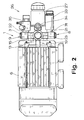
- FIG. 1 makes it clear in connection with FIG. 2 that the longitudinal axes of the central inlet 21 and the central outlet 22 are aligned parallel to one another.
- Fig. 5 it can be seen that there may also be a further connection 25 for either a separate connection line or a pulsation damper.
- the housing 10 of each pump unit 3 has an opening 24 closed by a threaded plug 23 on the side of the working space facing away from the bushing 11 of the piston rod 12.
- the housing 10 of the pump units 3 must be firmly connected to the carrier 13. This fixed connection is ensured in the illustrated embodiment by screw fastenings to be explained in more detail later. It is not shown in the drawings that the housing of the pump units on the carrier can be formed in one piece and the carrier u. U. can form a one-piece casting or pressed part with the housings. Brass, aluminum, and possibly also modern plastics, for example polyacetal, can be used as the material.
- the carrier 13 is U-shaped. This is expensive, especially with regard to the material consumption. According to an independent and independent teaching of the invention, the carrier 13 is now in the pump 1 shown here Solid-plate-shaped, it represents a solid support plate. This has the advantages explained above and solves the task in an independent way.
- the design of the carrier 13 as a solid support plate has the further advantage that, as shown here, the carrier 13 can be formed by the correspondingly designed bearing plate of the motor 6 designed as an electric motor. This is of course extremely cost-saving, since the anyway existing, anyway very solidly designed bearing plate now also serves as a solid backbone for the arrangement of the individual parts of pump 1. This completely saves the weight and cost of a separate carrier 13.
- the carrier 13 has an opening 14 for the passage of the drive shaft 7 in association with the force transmission element 5 of the drive unit 2.
- a special bearing for mounting the drive shaft 7 in the carrier 13 designed as a support plate is not required here in a particularly expedient manner because the carrier 13 here is the end shield of the electric motor 6 is.
- the bearing of the drive shaft 7 is thus actually the armature bearing of the electric motor 6 on the output side.
- the pump 1 itself no longer needs a bearing for its drive shaft 7.
- the armature bearings of the electric motor 6 are therefore used in two ways, on the one hand as an armature bearing of the output shaft of the electric motor 6 , on the other hand, functionally, as a rotary bearing of the drive shaft of the pump 1.
- FIG. 3 to 5 show how the housing 10 can be connected to the carrier 13.
- Welded connections, soldered connections, clamped connections, snap-in connections, etc. could be provided here, but specifically, as in the prior art, screw fastenings 15 are implemented.
- These screw fastenings 15 could comprise threaded shafts as in the prior art, but in the exemplary embodiment shown it applies that the support 13 has a plurality of threaded connections, in particular two threaded connections per pump unit 3 Has screw fasteners 15 into which fastening screws 16 can be screwed.
- the housings 10 of the pump units 3 have corresponding through bores 17 for the fastening screws 16.
- the screw fastenings 15 designed as threaded connections and the push-through bores 17 have centering surfaces 18 which correspond to one another. These centering surfaces 18 are expediently slightly conical in order to facilitate attachment of the pump 1 to the carrier 13.
- the design of the threaded connector allows particularly practical integration into a support 13 designed as a solid support plate.
- the carrier 13, here in the form of the end shield of the electric motor 6, serves as the backbone of the pump 1, so to speak.
- the mutual exact position of the various functional assemblies of the pump 1 is thus ensured by the carrier 13. Consequently, the functional assemblies, in particular the pump units 3, must be able to be brought into a very exact relative position to the carrier 13.
- the adjustment surfaces 19 which can be seen in FIGS. 2 and 3 are used for this purpose, which are dimensioned very precisely and are designed to be largely wear-resistant.
- the housing 10 can be clamped against these adjustment surfaces 19 with the aid of the fastening screws 16.
- the pump 1 in the exemplary embodiment shown is constructed in such a way that the adjusting surfaces 19 seen from the drive unit 2 are beyond the screw fastenings 15, preferably as far as possible beyond are arranged.
- the force transmission element is also essentially U-shaped with laterally projecting piston rods 12. This can be seen particularly clearly in FIG. 5.
- the drive element 4 is a cam roller.
- Such cam rollers are commercially available and ultimately represent nothing more than a cylinder-jacket-shaped outer ring made of highly wear-resistant material, which can be rotated with respect to a concentrically arranged inner ring via a sealed ball bearing or roller bearing. A permanent fat filling is usually provided at the same time.
- the inner ring can be fixed at any point.
- This construction of the drive element 4 corresponds in a particularly expedient manner to the construction of the force transmission element 5 with an essentially U-shaped cross section.
- Fig. 5 shows with the broken line of the drive element 4 and the drive shaft 7 that a particularly simple and expedient attachment of the drive element 4 to the drive shaft 7 has been realized, which is particularly suitable for the case that the drive shaft 7 is formed by the output shaft of the electric motor 6. It is namely the case here that the cam roller forming the drive element 4 is mounted with its axis of rotation offset eccentrically to the longitudinal axis of the drive shaft 7 on the end face of the drive shaft 7.
- the overall open construction corresponds to the fact that the power transmission surfaces of the drive element 4 and the power transmission element 5 coming into contact with one another consist of wear-resistant and / or self-lubricating, in particular graphite-containing material.
- Fig. 2 shows that the pump 1 is followed by a bypass device 26, as is known as such from the prior art.
- the bypass device 26 is hydraulically connected between the central outlet 22 and the central inlet 21 and has a pressure relief valve 27 connected downstream of the central outlet 22 and a return line 28 leading from the pressure relief valve 27 to the central inlet 21.
- 6 shows the bypass device 26 in somewhat more detail. It follows from this that the bypass device 26 is also designed as an open construction, that is to say with an exposed pressure relief valve 27, an exposed return line 28, connecting lines 29, etc. It applies that the bypass device 26 consists essentially of plastic, in particular polyacetal, and is preferably designed as an injection molded part.
- Fig. 6 shows that individual parts can be designed as screw inserts made of metal, as is known per se in comparable constructions. 6 shows that the individual parts of the bypass device 26 are connected and stiffened via stiffening webs 30.
- FIG. 1 shows in connection with Fig. 5 that in the embodiment shown here, the central inlet 21 has an elongated connector 31.
- This elongated connecting piece 31 can now be used in connection with a corresponding design of the central outlet 22 for fastening the bypass device 26 to the pump 1.
- the elongated connection piece 31 has a lateral bore 32, so that liquid can enter the connection piece 31 from the outside.
- the bypass device 26 has, as shown particularly clearly in FIG. 1, an elongated sleeve 33.
- the return line 28 from the pressure relief valve 27 opens into the sleeve 33. If the sleeve 33 is now pushed over the connecting piece 31 when the bypass device 26 is attached, this can be done in such a way that the bore 32 is aligned with the mouth of the return line 28 into the sleeve 33 .
- the bypass device 26 shown in detail in FIG. 6 also has a manometer 34 assigned to the pressure relief valve 27.
- the pressure relief valve 27 as such is designed in a manner known per se as a piston valve with two piston surfaces of different sizes.
- the central outlet 22 is followed by an injection unit 35, which operates in the manner of a water jet pump and allows chemicals to be injected or sucked into the pumped liquid.
- housings 10, manifolds 20, etc. consist of, optionally cast or pressed, brass, aluminum or the like, or of plastic, in particular of polyacetal.
Abstract
Bei einer Hochdruckpumpe (1) für Flüssigkeiten oder Gase mit einer Antriebseinheit (2) und mindestens einer mit der Antriebseinheit (2) verbundenen Pumpeinheit (3), bei der die Antriebseinheit (2) über ein Antriebselement (4), an eine von einem Motor 96) angetriebene Antriebswelle ankuppelbar ist, wird eine erhebliche vereinfachung im Sinne einer Produktion in großen Stückzahlen mit geringsten Kosten dadurch erreicht, daß jede Pumpeinheit (3) ein eigenes, von der Antriebseinheit (2) getrenntes, geschlossenes Gehäuse, das Gehäuse einen Einlaß (8), einen Auslaß (9) und eine druckdichte Durchführung für eine mit einem Pumpenkolben verbundene Kolbenstange der Antriebseinheit (2) aufweist, die den Pumpenkolben zugeordneten Kolbenstangen über ein Kraftübertragungselement (5) der Antriebseinheit (2) miteinander verbunden sind, eine massive, formstabile Tragplatte (13) vorgesehen ist, zumindest die Gehäuse der Pumpeinheiten (3) mit der Tragplatte (13) fest verbunden sind und so die Pumpeinheiten (3) und die Antriebseinheit (2) in ihrer Relativlage zueinander fixiert sind.In a high pressure pump (1) for liquids or gases with a drive unit (2) and at least one pump unit (3) connected to the drive unit (2), in which the drive unit (2) via a drive element (4) to one of a motor 96) driven drive shaft can be coupled, a considerable simplification in the sense of production in large quantities at the lowest cost is achieved in that each pump unit (3) has its own, separate from the drive unit (2), closed housing, the housing an inlet (8 ), an outlet (9) and a pressure-tight bushing for a piston rod of the drive unit (2) connected to a pump piston, the piston rods assigned to the pump pistons being connected to one another via a force transmission element (5) of the drive unit (2), a solid, dimensionally stable support plate (13) is provided, at least the housing of the pump units (3) are firmly connected to the support plate (13) and so the pump unit en (3) and the drive unit (2) are fixed in their relative position to each other.
Description
Die Erfindung betrifft eine Pumpe nach dem Oberbegriff von Anspruch 1.The invention relates to a pump according to the preamble of
Die bekannte Pumpe, von der die Erfindung ausgeht (US-A 3,697,197), dient zum gleichzeitigen Pumpen von Flüssigkeit und Luft beispielsweise in einer Eiskrem-Herstellungsmaschine. Die hier angewendeten Drücke liegen wenig über Atmosphärendruck bis maximal 2 bar.The known pump from which the invention is based (US Pat. No. 3,697,197) is used for the simultaneous pumping of liquid and air, for example in an ice cream manufacturing machine. The pressures used here are slightly above atmospheric pressure up to a maximum of 2 bar.
Die bekannte, für einen geringen Druck bestimmte und geeignete Pumpe ist ein vom antreibenden Motor, häufig einem Elektromotor, unabhängiges Aggregat, das lediglich antriebstechnisch über eine Flanschverbindung mit dem Elektromotor bzw. dem Motorgehäuse verbunden ist. Die Pumpe ist dabei in sehr zweckmäßiger, nämlich sehr einfacher, leichter und preisgünstiger Weise modular aufgebaut. Den Zusammenhalt aller Teile der Pumpe gewährleistet ein als U-förmiger Rahmen ausgeführter Träger, der mit seinem plattenartigen Steg am Lagerschild des Motors angeflanscht ist. An den jedenfalls plattenartigen U-Schenkeln des Trägers sind die beiden Pumpeinheiten spiegelsymmetrisch zueinander angeordnet. Die Gehäuse der Pumpeinheiten sind relativ zerklüftet gestaltet und weisen einerseits einen röhrenförmigen Teil mit Einlaß und Auslaß und zur Aufnahme eines Saugventils bzw. eines Druckventils, andererseits einen von dem röhrenförmigen Teil rechtwinklig abragenden, zylindrischen Teil als Arbeitsraum und zur Führung eines Pumpenkolbens auf. Ventilkörper des Saugventils und Druckventils können in die endseitigen Öffnungen der Gehäuse eingesetzt und die endseitigen Öffnungen können daraufhin mit Endkappen geschlossen werden. Eine vollständige Verspannung aller Teile erfolgt durch Ansetzen der Pumpeinheiten an den Träger.The known pump, which is intended and suitable for a low pressure, is a unit which is independent of the driving motor, often an electric motor, and which is only connected to the electric motor or the motor housing via a flange connection. The pump is modular in a very convenient, namely very simple, light and inexpensive way. The cohesion of all parts of the pump is ensured by a support designed as a U-shaped frame, which is flanged to the motor end shield with its plate-like web. The two pump units are arranged mirror-symmetrically to one another on the plate-like U-legs of the carrier. The housings of the pump units are relatively jagged and on the one hand have a tubular part with inlet and outlet and for receiving a suction valve or a pressure valve, on the other hand a cylindrical part protruding from the tubular part at right angles as a working space and for guiding a pump piston. Valve body of the suction valve and pressure valve can be inserted into the end openings of the housing and the end openings can then be closed with end caps. All parts are fully braced by attaching the pump units to the carrier.
Die Durchführungen für die Kolbenstangen bzw. die die Kolbenstangen bildenden Pumpenkolben an den beiden Gehäusen der Pumpeinheiten sind an den Längsseiten der Gehäuse angeordnet und zueinander fluchtend aufeinander ausgerichtet. Die Pumpenkolben sind mit einem U-förmigen Kraftübertragungselement zusammengefaßt. In das Kraftübertragungselement greift eine Kurvenrolle als Antriebselement der Antriebseinheit ein. Die Kurvenrolle sitzt mit ihrer Drehachse exzentrisch zur Längsachse der Antriebswelle an deren Stirnseite. Ggf. kann hier eine passende Dauerschmierung vorgesehen sein. Diese offene Konstruktion ergibt von selbst eine gute Kühlung insbesondere im Bereich der Antriebseinheit mit Antriebselement und Kraftübertragungselement.The bushings for the piston rods or the pump pistons forming the piston rods on the two housings of the pump units are arranged on the long sides of the housings and are aligned with one another. The pump pistons are combined with a U-shaped power transmission element. A cam roller engages in the power transmission element as the drive element of the drive unit. The cam roller sits with its axis of rotation eccentrically to the longitudinal axis of the drive shaft on the end face. Possibly. A suitable permanent lubrication can be provided here. This open construction naturally results in good cooling, particularly in the area of the drive unit with drive element and power transmission element.
Die bekannte Pumpe ist insoweit noch besonders zweckmäßig, als der Träger in Zuordnung zum Kraftübertragungselement der Antriebseinheit eine Öffnung zum Durchtritt der Antriebswelle aufweist. Da der Träger mit dem plattenförmigen U-Steg unmittelbar an das Lagerschild des Motors angeflanscht werden kann, läßt sich so beispielsweise bei Verwendung eines Elektromotors als Lager der Antriebswelle das abtriebsseitige Lager der Abtriebswelle, nämlich das abtriebsseitige Ankerlager des Elektromotors nutzen.The known pump is particularly expedient insofar as the carrier has an opening for the passage of the drive shaft in association with the power transmission element of the drive unit. Since the carrier with the plate-shaped U-web can be flanged directly to the end shield of the motor, the output-side bearing of the output shaft, namely the output-side armature bearing of the electric motor, can be used, for example, when using an electric motor as the bearing of the input shaft.
Die Befestigung der beiden Pumpeinheiten an den U-Schenkeln des Trägers erfolgt von deren Außenseite her, wobei der den Arbeitsraum bildende, senkrecht abragende Teil des Gehäuses durch eine entsprechend geformte Öffnung im U-Schenkel hindurchgesteckt wird. Vom Träger ragen seitlich Gewindestangen ab, auf die die Gehäuse mit Hilfe von Durchsteckbohrungen aufgeschoben werden können. Ein die Öffnung zum Durchtritt des den Arbeitsraum aufweisenden Teils des Gehäuses umgebender flanschartiger Rand wirkt mit einem Ringflansch am Gehäuse jeder Pumpeinheit selbst so zusammen, daß durch Spannen der Pumpeinheiten diese gleichzeitig aufeinander ausgerichtet und justiert werden.The two pump units are attached to the U-legs of the carrier from the outside thereof, the part of the housing which projects vertically and which forms the working space is inserted through a correspondingly shaped opening in the U-leg. Threaded rods protrude laterally from the carrier, onto which the housings can be pushed using push-through holes. A flange-like edge surrounding the opening for the passage of the part of the housing which has the working space cooperates with an annular flange on the housing of each pump unit itself in such a way that the pump units are simultaneously aligned and adjusted to one another by tensioning the pump units.
Die bekannte, zuvor erläuterte Pumpe ist für höhere Drücke aus vielen Gründen nicht geeignet. Einerseits ist die Notwendigkeit, die beiden Pumpeinheiten der Pumpe miteinander über Schlauchleitungen in relativ komplizierter Führung zu verbinden, für Hochdruckanwendungen problematisch, da sich durch die Schlauchleitungen jeweils Schwachstellen ergeben. Jedenfalls sind derartige Schlauchleitungen für hohe Drücke über 20 bar ausgesprochen teuer. Außerdem sind für hohe Drücke natürlich auch entsprechend hohe Antriebsleistungen erforderlich, die entsprechend erheblich erhöhte Material stärken erfordern. Auch das schlägt sich sofort in erheblich höheren Preisen nieder. Im Ergebnis wird eine Pumpe der in Rede stehenden Art, die man so verstärkt, daß sie für Drücke über 20 bar geeignet ist, ebenso teuer oder teurer als speziell für diese Druckbereiche entwickelte, anders konstruierte Hochdruckpumpen.The known pump explained above is not suitable for higher pressures for many reasons. On the one hand, the need to connect the two pump units of the pump to one another via hose lines in a relatively complicated manner is problematic for high-pressure applications, since weak points result in each case from the hose lines. In any case, such hose lines are extremely expensive for high pressures above 20 bar. In addition, of course, correspondingly high drive powers are required for high pressures, the correspondingly significantly increased material require strengths. This is also immediately reflected in significantly higher prices. As a result, a pump of the type in question, which is amplified so that it is suitable for pressures above 20 bar, becomes just as expensive or more expensive than specially designed high-pressure pumps specially developed for these pressure ranges.
Aus der Praxis bekannte Hochdruckpumpen, also Pumpen für einen Druckbereich von 20 bar bis 100 bar, insbesondere einen Druckbereich von 40 bar bis 80 bar, sind in erster Linie deshalb so teuer, weil man auf ein großes und schweres, allumfassendes Gehäuse aus Metall nicht verzichten zu können glaubt. Dieses Gehäuse ist normalerweise mit dem Motorblock eines Antreibsmotors über eine weitere Tragkonstruktion verflanscht. Gleichzeitig wird eine im Gehäuse selbst zweifach gelagerte Antriebswelle der Hochdruckpumpe über eine zwischen dem Gehäuse des Antriebsmotors und dem Gehäuse der Hochdruckpumpe liegende Flanschverbindung verbunden.High-pressure pumps known from practice, i.e. pumps for a pressure range from 20 bar to 100 bar, in particular a pressure range from 40 bar to 80 bar, are primarily so expensive because one does not have to do without a large and heavy, all-encompassing metal housing believes to be able to. This housing is usually flanged to the engine block of a drive motor via another support structure. At the same time, a drive shaft of the high-pressure pump, which is mounted twice in the housing itself, is connected via a flange connection located between the housing of the drive motor and the housing of the high-pressure pump.
Der Erfindung liegt nun die Aufgabe zugrunde, die bekannte Pumpe mit modularem Aufbau mit geringem Material- und Kostenaufwand so zu gestalten, daß sie als preisgünstiges Produkt für einen Einsatz bei hohen Drücken über 20 bar geeignet ist.The invention is based on the object of designing the known pump with a modular structure with low material and cost expenditure so that it is suitable as an inexpensive product for use at high pressures above 20 bar.
Bei der erfindungsgemäßen Pumpe ist die zuvor aufgezeigte Aufgabe durch die Merkmale des kennzeichnenden Teils von Anspruch 1 gelöst. Erfindungsgemäß bleibt es bei dem modularen Aufbau der Pumpe. Durch die geschickte Anordnung der Einlässe und Auslässe an den Gehäusen der Pumpeinheiten wird aber erreicht, daß sämtliche Leitungen extrem kurz und optimal gerade geführt werden können. Ferner wird dadurch erreicht, daß die durch das Pumpen bei hohem Druck auftretenden erheblichen Kräfte an Einlässen und Auslässen der beiden Pumpeinheiten hinsichtlich der Kraftwirkung einander genau entgegengerichtet sind, so daß sie sich gegenseitig kompensieren und jedenfalls am Träger optimal abfangbar sind. Die Gehäuse der Pumpeinheiten bilden nämlich für diese Kräfte von selbst die optimalen Widerlager. Im Ergebnis reicht für eine hochdruckfeste Gestaltung der Pumpe wegen der er findungsgemäßen konstruktiven Anordnung der einzelnen Teile eine stabile Gestaltung der Gehäuse und eine stabile Gestaltung des Trägers aus, so daß die Herstellungskosten erheblich niedriger sind als bei den bislang bekannten, ein einteiliges Gehäuse aufweisenden Hochdruckpumpen.In the pump according to the invention, the object outlined above is achieved by the features of the characterizing part of
Grundsätzlich gilt, daß die zuvor erläuterte, modulare Pumpe für den Hochdruckbereich auch mit nur einer Pumpeinheit arbeiten kann, aus Gründen der dynamischen und statischen Optimierung wird man aber meist zwei Pumpeinheiten symmetrisch zueinander wählen, wie das im Stand der Technik auch stets gemacht wird. Hinsichtlich der Druck- und Saugventile empfiehlt es sich, diese in das Gehäuse vollständig zu integrieren, also insoweit herausnehmbare Schraubeinsätze zu verwirklichen, wie sie für Hochdruckpumpen als solche bekannt sind.Basically, the modular pump for the high pressure range explained above can also work with only one pump unit, but for reasons of dynamic and static optimization, two pump units will usually be selected symmetrically to one another, as is always done in the prior art. With regard to the pressure and suction valves, it is advisable to fully integrate them into the housing, in other words to implement removable screw inserts, as are known as such for high-pressure pumps.
Es gibt nun eine Vielzahl von Möglichkeiten, die Lehre der Erfindung auszugestalten und weiterzubilden, wozu zunächst auf die dem Anspruch 1 nachgeordneten Ansprüche verwiesen werden darf. Darunter kommt einer Lehre der Erfindung eine besondere und eigenständige Bedeutung zu, wonach der Träger massiv-plattenförmig, gewissermaßen also als massive, formstabile Tragplatte ausgeführt ist. Im Rahmen dieser Lehre der Erfindung wird also eine besondere Vereinfachung des Aufbaus der Pumpe und damit eine eigenständige Lösung der Aufgabenstellung dadurch erzielt, daß der Träger nicht mehr als U-förmiger Rahmen, sondern als ebene Tragplatte ausgeführt ist. Erfindungsgemäß ist erkannt worden, daß die U-Schenkel des bekannten Trägers zur genauen Fixierung der Relativlage der einzelnen Teile der Pumpe gar nichts beitragen. Diese Fixierung kann ganz genau so erreicht werden, wenn der Träger lediglich eine ebene Tragplatte ist und man die Gehäuse der Pumpeinheiten entsprechend etwas anders gestaltet. Damit aber wird erhebliches Material eingespart und eine erhebliche Kostenreduzierung herbeigeführt. Im übrigen ergibt sich dadurch die Möglichkeit, das dementsprechend gestaltete Lagerschild eines als Elektromotor ausgeführten Motors als diese Tragplatte zu nutzen. Bei dieser Ausgestalltung wird also auf eine gesonderte Tragplatte verzichtet und die einzelnen Teile der Pumpe werden unmittelbar an das Lagerschild des Elektromotors angeschraubt.There are now a multitude of possibilities for developing and developing the teaching of the invention, for which purpose reference may first be made to the claims subordinate to claim 1. Below this, a teaching of the invention is of particular and independent importance, according to which the carrier is designed in the form of a solid plate, that is to say, as a solid, dimensionally stable supporting plate. In the context of this teaching of the invention, a particular simplification of the construction of the pump and thus an independent solution to the task is achieved in that the carrier is no longer designed as a U-shaped frame, but as a flat support plate. According to the invention, it has been recognized that the U-legs of the known carrier do not contribute at all to the exact fixing of the relative position of the individual parts of the pump. This fixation can be achieved in exactly the same way if the carrier is merely a flat support plate and the housing of the pump units is designed somewhat differently accordingly. This, however, saves considerable material and brings about a significant reduction in costs. Otherwise, this results in the possibility of using the correspondingly designed bearing plate of a motor designed as an electric motor as this support plate. In this configuration, a separate support plate is therefore dispensed with and the individual parts of the pump are screwed directly onto the end shield of the electric motor.
Im folgenden werden nun die weiteren bevorzugten Ausgestaltungen und Weiterbildungen der Erfindung anhand der Erläuterung eines bevorzugten Ausführungsbeispiels anhand der Zeichnung näher behandelt. In der Zeichnung zeigt
- Fig. 1 in perspektivischer Ansicht, sehr schematisch, eine an einem Elektromotor angeflanschte Pumpe für hohen Druck,
- Fig. 2 in Seitenansicht, gleichfalls sehr schematisch, einen Elektromotor mit angeflanschter Pumpe und Bypassvorrichtung,
- Fig. 3 eine Tragplatte der Pumpe in einer Ansicht,
- Fig. 4 den Gegenstand aus Fig. 3 im Schnitt entlang der Linie IV - IV,
- Fig. 5 in perspektivischer Ansicht eine Pumpe von der Antriebsseite aus gesehen und
- Fig. 6 in perspektivischer Ansicht eine Bypassvorrichtung von der Anschlußseite her gesehen.
- 1 in a perspective view, very schematically, a pump flanged to an electric motor for high pressure,
- 2 is a side view, also very schematically, of an electric motor with a flange-mounted pump and bypass device,
- 3 shows a support plate of the pump in a view,
- 4 shows the object from FIG. 3 in section along the line IV-IV,
- Fig. 5 seen in perspective view of a pump from the drive side and
- Fig. 6 seen in perspective view of a bypass device from the connection side.
Dargestellt ist eine Pumpe 1 für Flüssigkeiten oder Gase, insbesondere für Wasser, mit einer Antriebseinheit 2 und mindestens einer mit der Antriebseinheit 2 verbundenen Pumpeinheit 3, hier zwei gleichartige, symmetrisch zur Antriebseinheit 2 angeordnete und mit der Antriebseinheit 2 verbundene Pumpeinheiten 3. Die Antriebseinheit 2 ist über ein Antriebsselement 4, das in Fig. 5 gestrichelt dargestellt ist und hier die Form eines Exzenternockens hat, und ein mit dem Antriebselement 4 in Eingriff stehendes Kraftübertragungselement 4, das ebenfalls in Fig. 5 zu erkennen und hier als Exzenterkäfig ausgeführt ist, an eine von einem Motor, hier und insbesondere einem Elektromotor 6, angetriebene Antriebswelle 7 ankuppelbar. Die Antriebswelle 7 ist gleichfalls in Fig. 5 gestrichelt dargestellt.Shown is a
Durch die Antriebseinheit 2 ist eine Drehbewegung der Antriebswelle 7 in eine Verschiebebewegung umwandelbar. Grundsätzlich gilt, daß die Antriebseinheit 2 aber auch so ausgestaltet sein kann, daß die vom Motor kommende Antriebsbewegung schon eine Verschiebebewegung ist, so daß eine Umwandlung innerhalb der Antriebseinheit 2 nicht mehr erforderlich ist.The
Jede Punpeinheit 3 weist in an sich bekannter und daher im einzelnen nicht dargestellter Weise einen Arbeitsraum mit einem an einem Einlaß 8 angeordneten Saugventil und einem an einem Auslaß 9 angeordneten Druckventil auf. Ferner weist jede Pumpeinheit 3 einen im Arbeitsraum druckdicht geführten, zum Pumpen im Arbeitsraum hin und her verschiebbaren Pumpenkolben auf. Die Pumpenkolben sind von der Antriebseinheit 2 antreibbar.In a manner known per se and therefore not shown in detail, each puncturing
Die Fig. 1 und 5 zeigen, daß jede Pumpeinheit 3 ein eigenes langgestreckt-blockartiges bzw. zylindrisches Gehäuse 10 mit dem Arbeitsraum, dem Einlaß 8, dem am Einlaß 8 angeordneten Saugventil, das hier in das Gehäuse 10 integriert ist, dem Auslaß 9, dem am Auslaß 9 angeordneten Druckventil, das hier ebenfalls in das Gehäuse 10 integriert ist, dem Pumpenkolben und einer an einer Längsseite des Gehäuses 10 angeordneten, druckdichten Durchführung 11 für eine mit dem Pumpenkolben verbundene bzw. den Pumpenkolben bildende Kolbenstange 12 aufweist. Interessant ist hier, daß die Antriebseinheit 2 gehäuselos ausgeführt ist, also nur aus den Kolbenstangen 12, dem Kraftübertragungselement 5 und dem Antriebselement 4 besteht. Die gegenseitige Relativlage dieser Teile wird durch einen formstabilen Träger 13 gewährleistet, mit dem die Gehäuse 10 der Pumpeinheiten 3 in genau bestimmter Lage fest verbunden sind. Die besonderen Vorteile dieser Konstruktion in modularer Bauweise sind oben schon erläutert worden. Das ist der Grundstein für eine auch im Hochdruckbereich besonders leichte und preisgünstige und damit als echtes Massenprodukt geeignete Pumpe 1.1 and 5 show that each
Durch die langgestreckt-blockartige bzw. zylindrische Gestalt der Gehäuse 10 ist die Grundlage für eine rahmenartige und damit besonders verwindungssteife Konstruktion der Pumpe 1 gelegt. Für die Erfindung wesentlich ist nun, daß für jede Pumpeinheit 3 an der die Durchführung 11 aufweisenden Längsseite des Gehäuses 10 endseitig auch der Einlaß 8 bzw. der Auslaß 9 angeordnet und die Längsachsen von Einlaß 8 und Auslaß 9 parallel zur Längsachse der Durchführung 11 ausgerichtet sind und daß die Gehäuse 10 mit den die Durchführung 11, den Einlaß 8 und den Auslaß 9 aufweisenden Längsseiten aufeinanderzu gerichtet am Träger 13 angeordnet sind. Das zeigt Fig. 5 in Verbindung mit Fig. 1 sehr deutlich. Hier gilt ferner, daß die Durchführungen 11, die Einlässe 8 und die Auslässe 9 zueinander fluchtend ausgerichtet sind. Dadurch ergibt sich einerseits eine extrem verwindungssteife, rahmenartige Konstruktion, ergeben sich andererseits lediglich gerade, möglichst kurze Leitungsstücke zwischen den Einlässen 8 und den Auslässen 9 der Gehäuse 10 und ergeben sich schließlich die eingangs erläuterten Vorteile hinsichtlich des Abfangens auftretender Kräfte beim Pumpbetrieb. Die zuvor zuletzt erläuterte, bevorzugte Konstruktion und Anordnung der Gehäuse 10 der Pumpeinheiten 3 an Träger 13 führt dazu, daß eine geringfügige Veränderung des Abstands der Pumpeinheiten 3 voneinander grundsätzlich für die Ausrichtung der Einlässe 8, Auslässe 9 und Durchführungen 11 ohne Belang ist.Due to the elongated block-like or cylindrical shape of the
Angepaßt an die zuvor erläuterte Konstruktion und Anordnung der Gehäuse 10 der Pumpeinheiten 3 ist hier ferner vorgesehen, daß die Einlässe 8 und Auslässe 9 der Gehäuse 10 der Pumpeinheiten 3 über eine Sammelleitung 20 jeweils miteinander und mit einem Zentraleinlaß 21 bzw. einem Zentralauslaß 22 verbunden sind. Hier gilt ferner, daß die Sammelleitungen 20 als gerade Leitungsstücke und der Zentraleinlaß 21 bzw. Zentralauslaß 22 als T-Stücke ausgeführt sind. Schließlich ist hier dargestellt, daß die Einlässe 8 und Auslässe 9 der Gehäuse 10 als druckdichte Steckfassungen für die Enden der als gerade Leitungsstücke ausgeführten Sammelleitungen 20 ausgeführt sind. Diese Gestaltung der hydraulischen Verbindung der beiden Pumpeinheiten 3 führt dazu, daß die beiden Gehäuse 10 der Pumpeinheiten 3 ohne weiteres in ihrem Abstand voneinander eingestellt werden können, ohne daß Undichtigkeiten auftreten. Die für die Sammelleitungen 20 als Schiebesitze ausgestalteten Einlässe 8 und Auslässe 9 erlauben es, den Abstand der Pumpeinheiten 3 über eine relativ großen Bereich zu verändern, ohne daß die relative Winkelstellung der Pumpeinheiten 3 verändert wird. Dabei dienen die Sammelleitungen 20 in den Steckfassungen der Einlässe 8 und Auslässe 9 zur Winkeljustierung der Gehäuse 10 der Pumpeinheiten 3.Adapted to the construction and arrangement of the
Fig. 1 macht im übrigen in Verbindung mit Fig. 2 deutlich, daß die Längsachsen des Zentraleinlasses 21 und des Zentralauslasses 22 parallel zueinander ausgerichtet sind. In Fig. 5 ist dabei zu erkennen, daß durchaus auch noch ein weiterer Anschluß 25 für entweder eine separate Anschlußleitung oder einen Pulsationsdämpfer vorhanden sein kann.1 makes it clear in connection with FIG. 2 that the longitudinal axes of the
Unter Umständen, beispielsweise bei einer einstückigen Ausführung der Gehäuse 10 mit der Tragplatte 13, aber auch aus Gründen der Säuberung und der Reparatur kann es zweckmäßig sein, wenn die Arbeitsräume in dem Gehäuse 10 der Pumpeinheiten 3 frei zugänglich sind. Dazu gilt für das hier vorgesehene Ausführungsbeispiel, daß das Gehäuse 10 jeder Pumpeinheit 3 auf der von der Durchführung 11 der Kolbenstange 12 abgewandten Seite des Arbeitsraums eine durch einen Gewindestopfen 23 verschlossene Öffnung 24 aufweist.Under certain circumstances, for example in the case of a one-piece design of the
Bislang ist nur darauf hingewiesen worden, daß die Gehäuse 10 der Pumpeinheiten 3 mit dem Träger 13 fest verbunden sein müssen. Diese feste Verbindung ist im dargestellten Ausführungsbeispiel durch später noch näher zu erläuternde Schraubbefestigungen gewährleistet. Nicht dargestellt ist in den Zeichnungen, daß die Gehäuse der Pumpeinheiten am Träger einstückig ausgeformt sein können und der Träger u. U. mit den Gehäusen ein einstückiges Gußteil oder Preßteil bilden kann. Als Material kommen Messing, Aluminium, evtl. auch moderne Kunststoffe, beispielsweise Polyacetal, in Frage.So far, it has only been pointed out that the
Im Stand der Technik ist, wie weiter oben erläutert worden ist, der Träger 13 U-förmig ausgeführt. Das ist aufwendig, insbesondere hinsichtlich des Materialverbrauchs. Nach einer eigenständigen und unabhängigen Lehre der Erfindung ist nun aber der Träger 13 bei der hier dargestellten Pumpe 1 massiv-plattenförmig ausgeführt, stellt also eine massive Tragplatte dar. Das hat die weiter oben erläuterten Vorteile und löst die Aufgabe in eigenständiger Weise.In the prior art, as has been explained above, the
Die Ausführung des Trägers 13 als massive Tragplatte hat den weiteren Vorteil, daß, wie hier dargestellt, der Träger 13 von dem entsprechend gestalteten Lagerschild des als Elektromotor ausgeführten Motors 6 gebildet werden kann. Das ist natürlich extrem kostensparend, da das sowieso vorhandene, sowieso sehr massiv gestaltete Lagerschild nun gleichzeitig als massives Rückgrat für die Anordnung der Einzelteile der Pumpe 1 dient. Damit werden Gewicht und Kosten eines gesonderten Trägers 13 komplett eingespart.The design of the
Bei der dargestellten Pumpe 1 weist der Träger 13 in Zuordnung zum Kraftübertragungselement 5 der Antriebseinheit 2 eine Öffnung 14 zum Durchtritt der Antriebswelle 7 auf. Das ergibt sich besonders deutlich aus Fig. 3 und Fig. 4. Ein besonderes Lager zum Lagern der Antriebswelle 7 in dem als Tragplatte ausgeführten Träger 13 bedarf es hier in besonders zweckmäßiger Weise deshalb nicht, weil der Träger 13 ja hier das Lagerschild des Elektromotors 6 ist. Das Lager der Antriebswelle 7 ist also tatsächlich das abtriebsseitige Ankerlager des Elektromotors 6. Damit benötigt die Pumpe 1 selbst überhaupt kein Lager mehr für ihre Antriebswelle 7. Die Ankerlager des Elektromotors 6 sind also in doppelter Weise genutzt, einerseits als Ankerlager der Abtriebswelle des Elektromotors 6, andererseits, funktionell, als Drehlager der Antriebswelle der Pumpe 1.In the
Die Fig. 3 bis 5 zeigen, wie die Gehäuse 10 mit dem Träger 13 verbunden werden können. Es könnten hier Schweißverbindungen, Lötverbindungen, Klemmverbindungen, Rastverbindungen usw. vorgesehen sein, konkret sind aber, wie beim Stand der Technik, Schraubbefestigungen 15 verwirklicht. Diese Schraubbefestigungen 15 könnten Gewindeschäfte wie beim Stand der Technik umfassen, im dargestellten Ausführungsbeispiel gilt aber, daß der Träger 13 mehrere, insbesondere je Pumpeinheit 3 zwei Gewindestutzen als Schraubbefestigungen 15 aufweist, in die Befestigungsschrauben 16 eingeschraubt werden können. Die Gehäuse 10 der Pumpeinheiten 3 weisen entsprechende Durchsteckbohrungen 17 für die Befestigungsschrauben 16 auf. Besonders zweckmäßig ist es nun, daß hier die als Gewindestutzen ausgeführten Schraubbefestigungen 15 und die Durchsteckbohrungen 17 zueinander korrespondierend ausgebildete Zentrierflächen 18 aufweisen. Diese Zentrierflächen 18 sind zweckmäßigerweise leicht konisch ausgebildet, um ein Ansetzen der Pumpe 1 an den Träger 13 zu erleichtern. Die Ausführung der Gewindestutzen erlaubt eine besonders praktische Integration in einen als massive Tragplatte ausgeführten Träger 13.3 to 5 show how the
Wie zuvor mehrfach schon angesprochen worden ist, dient der Träger 13, hier in Form des Lagerschilds des Elektromotors 6, gewissermaßen als Rückgrat der Pumpe 1. Die gegenseitige exakte Relativlage der verschiedenen Funktionsbaugruppen der Pumpe 1 wird also durch den Träger 13 gewährleistet. Folglich müssen die Funktionsbaugruppen, also insbesondere die Pumpeinheiten 3, in eine ganz exakte Relativlage zum Träger 13 gebracht werden können. Dazu dienen die in den Fig. 2 und 3 erkennbaren Justierflächen 19, die ganz exakt bemessen und weitestgehend verschleißfest ausgeführt sind. Gegen diese Justierflächen 19 sind die Gehäuse 10 spannbar mit Hilfe der Befestigungsschrauben 16. Es kommt hier insbesondere auf die Winkelstellung der Pumpeinheiten 3 zueinander und zur Antriebseinheit 2 an, die im Zusammenwirken von Zentrierflächen 18 einerseits und Justierflächen 19 andererseits optimal einstellbar ist. Im Betrieb werden durch die auftretenden Kräfte auf die Gehäuse 10 erhebliche Koppkräfte ausgeübt, die ohne Gegenmaßnahmen eine Verkippung der Gehäuse 10 nach außen bewirken würden. Um die Kippkräfte nicht vollständig an den Befestigungsschrauben 16, Gewindestutzen 15 und Zentrierflächen 18 abfangen zu müssen, ist die Pumpe 1 im dargestellten Ausführungsbeispiel so konstruiert, daß die Justierflächen 19 von der Antriebseinheit 2 aus gesehen jenseits der Schraubbefestigungen 15, vorzugsweise so weit jenseits wie möglich, angeordnet sind. Durch diese Maßnahme besteht der längstmögliche Hebelarm zwischen Justierflächen 19 und Befestigungsschrauben 16, so daß alle Kippkräfte über diesen Hebelarm in die Justierflächen 19 und damit in den Träger 13 abgeleitet werden können. Damit ist sichergestellt, daß die befestigungsschrauben 16 praktisch überhaupt nicht auf Kippung beansprucht werden. Auch im Vollastbetrieb ist so eine exakte Einhaltung der relativen Winkelstellung der Pumpeinheiten 3 zueinander und zur Antriebseinheit 2 sichergestellt.As has already been mentioned several times before, the
Wie im Stand der Technik ist auch hier das Kraftübertragungselement im wesentlichen U-förmig mit seitlich abragenden Kolbenstangen 12 ausgeführt. Das zeigt besonders deutlich Fig. 5. Weiter ist erkennbar, daß hier als ein bevorzugtes Ausführungsbeispiel das Antriebselement 4 eine Kurvenrolle ist. Derartige Kurvenrollen sind handelsüblich zu erwerben und stellen letztlich nichts weiter dar als einen zylindermantelförmigen Außenring aus hochverschleißfestem Material, der über ein allseits abgedichtetes Kugellager oder Rollenlager gegenüber einem konzentrisch angeordneten Innenring drehbar ist. Zumeist ist gleichzeitig eine Dauerfettfüllung vorgesehen. Der Innenring läßt sich an beliebiger Stelle ortsfest anbringen. Diese Konstruktion des Antriebselements 4 korrespondiert in besonders zweckmäßiger Weise zur Konstruktion des Kraftübertragungselements 5 mit im wesentlichem U-förmigem Querschnitt.As in the prior art, the force transmission element is also essentially U-shaped with laterally projecting
Fig. 5 läßt mit der gestrichelten Darstellung des Antriebselements 4 und der Antriebswelle 7 erkennen, daß hier eine besonders einfache und zweckmäßige Anbringung des Antriebselements 4 an der Antriebswelle 7 realisiert worden ist, die sich in ganz besonders zweckmäßiger Weise auch für den Fall eignet, daß die Antriebswelle 7 durch die Abtriebswelle des Elektromotors 6 gebildet ist. Es gilt nämlich, daß hier die das Antriebselement 4 bildende Kurvenrolle mit ihrer Drehachse exzentrisch zu der Längsachse der Antriebswelle 7 versetzt an der Stirnseite der Antriebswelle 7 gelagert ist.Fig. 5 shows with the broken line of the
Der insgesamt offenen Konstruktion entspricht es, daß die aneinander zur Anlage kommenden Kraftübertragungsflächen von Antriebselement 4 und Kraftübertragungselement 5 aus verschleißfestem und/oder selbstschmierendem, insbesondere graphithaltigem Material bestehen.The overall open construction corresponds to the fact that the power transmission surfaces of the
Fig. 2 zeigt, daß der Pumpe 1 eine Bypassvorrichtung 26 nachgeschaltet ist, wie sie als solche aus dem Stand der Technik bekannt ist. die Bypassvorrichtung 26 ist hydraulisch zwischen den Zentralauslaß 22 und den Zentraleinlaß 21 geschaltet und weist ein dem Zentralauslaß 22 nachgeschaltetes Überdruckventil 27 sowie eine vom Überdruckventil 27 zum Zentraleinlaß 21 führende Rücklaufleitung 28 auf. Fig. 6 zeigt die Bypassvorrichtung 26 etwas genauer. Daraus ergibt sich, daß auch die Bypassvorrichtung 26 als offene Konstruktion, also mit freiliegendem Überdruckventil 27, freiliegender Rücklaufleitung 28, Verbindungsleitungen 29 etc. ausgeführt ist. Dabei gilt, daß die Bypassvorrichtung 26 im wesentlichen aus Kunststoff, insbesondere aus Polyacetal, besteht und, vorzugsweise, als Spritzgußteil ausgeführt ist. Fig. 6 zeigt, daß einzelne Teile als Schraubeinsätze aus Metall ausgeführt sein können, wie das für sich bei vergleichbaren Konstruktionen bekannt ist. Im übrigen zeigt Fig. 6, daß die einzelnen Teile der Bypassvorrichtung 26 über Versteifungsstege 30 miteinander verbunden und versteift sind.Fig. 2 shows that the
Fig. 2 läßt erkennen, wie die Bypassvorrichtung 26 an der Pumpe 1 angesetzt sein kann. Fig. 1 läßt in Verbindung mit Fig. 5 erkennen, daß im hier dargestellten Ausführungsbeispiel der Zentraleinlaß 21 einen langgestreckten Stutzen 31 aufweist. Dieser langgestreckte Stutzen 31 kann nun dazu genutzt werden, in Verbindung mit einer entsprechenden Gestaltung des Zentralauslasses 22 zur Befestigung der Bypassvorrichtung 26 an der Pumpe 1 zu dienen. Dazu weist der langgestreckte Stutzen 31 eine seitliche Bohrung 32 auf, so daß Flüssigkeit von außen in den Stutzen 31 eintreten kann. Die Bypassvorrichtung 26 weist, wie insbesondere Fig. 1 deutlich zeigt, eine langgestreckte Hülse 33 auf. Die Rücklaufleitung 28 vom Überdruckventil 27 mündet in die Hülse 33. Wird nun die Hülse 33 beim Ansetzen der Bypassvorrichtung 26 über den Stutzen 31 geschoben, so kann das so geschehen, daß die Bohrung 32 etwa mit der Mündung der Rücklaufleitung 28 in die Hülse 33 fluchtet.2 shows how the
Die in Fig. 6 im einzelnen dargestellte Bypassvorrichtung 26 weist im übrigen noch ein dem Überdruckventil 27 zugeordnetes Manometer 34 auf.The
Das überdruckventil 27 als solches ist in an sich bekannter Weise als Kolbenventil mit zwei unterschiedlich großen Kolbenflächen ausgeführt. Im übrigen ist dem Zentralauslaß 22 noch eine Injektionseinheit 35 nachgeordnet, die nach Art einer Wasserstrahlpumpe arbeitet und das Injizieren bzw. Einsaugen von Chemikalien in die gepumpte Flüssigkeit erlaubt.The
Ganz generalle gilt, daß die Gehäuse 10, Sammelleitungen 20 etc. aus, ggf. gegossenem oder gepreßtem, Messing, Aluminium od. dgl. oder aus Kunststoff, insbesondere aus Polyacetal, bestehen.The general rule is that the
Claims (10)
Applications Claiming Priority (2)
| Application Number | Priority Date | Filing Date | Title |
|---|---|---|---|
| DE3705608A DE3705608C3 (en) | 1987-02-21 | 1987-02-21 | Pump for liquids or gases, especially for water |
| DE3705608 | 1987-02-21 |
Publications (2)
| Publication Number | Publication Date |
|---|---|
| EP0279910A2 true EP0279910A2 (en) | 1988-08-31 |
| EP0279910A3 EP0279910A3 (en) | 1989-11-23 |
Family
ID=6321491
Family Applications (1)
| Application Number | Title | Priority Date | Filing Date |
|---|---|---|---|
| EP87116030A Ceased EP0279910A3 (en) | 1987-02-21 | 1987-10-31 | Pump with a modular assembly |
Country Status (4)
| Country | Link |
|---|---|
| US (1) | US4824335A (en) |
| EP (1) | EP0279910A3 (en) |
| JP (1) | JPS6463667A (en) |
| DE (1) | DE3705608C3 (en) |
Cited By (1)
| Publication number | Priority date | Publication date | Assignee | Title |
|---|---|---|---|---|
| DE4008255C1 (en) * | 1990-03-15 | 1991-07-11 | Suttner Gmbh & Co Kg, 4800 Bielefeld, De | Component for high pressure pumps, compressor etc. - has high tensile strength housing, forming trough-shaped retainer for plastics moulding, open to one side |
Families Citing this family (9)
| Publication number | Priority date | Publication date | Assignee | Title |
|---|---|---|---|---|
| DE3835233A1 (en) * | 1988-10-15 | 1990-04-19 | Hsm Pressen Gmbh | ELECTRO-HYDRAULIC MOTOR PUMP UNIT |
| US4978284A (en) * | 1990-03-01 | 1990-12-18 | Cook James E | Double acting simplex plunger pump |
| US5520520A (en) * | 1995-03-28 | 1996-05-28 | Nakamoto; Tomijiko | Pneumatically operated double acting pump for viscous food stuffs |
| DE19922947A1 (en) * | 1999-05-14 | 2000-11-23 | Mannesmann Ag | Drive unit for hydraulic consumers of individual components of a machine |
| US6851938B2 (en) * | 2001-08-28 | 2005-02-08 | Vanderbilt University | Magnetic pumping system |
| GB2463821B (en) * | 2005-05-17 | 2010-06-09 | Thomas Industries Inc | Pump improvements |
| CA2662498C (en) * | 2006-09-05 | 2014-10-28 | Gardner Denver Thomas, Inc. | Fluid intake and exhaust fittings for a compressor or pump |
| WO2014151315A1 (en) | 2013-03-15 | 2014-09-25 | Delaware Capital Formation, Inc. | Seal-less piston pump for liquefied gas |
| US10087921B2 (en) * | 2016-01-27 | 2018-10-02 | Ge Oil & Gas Compression Systems, Llc | Preventing deformation of frame on a reciprocating compressor |
Citations (10)
| Publication number | Priority date | Publication date | Assignee | Title |
|---|---|---|---|---|
| US1388780A (en) * | 1920-11-29 | 1921-08-23 | Arthur E Stanley | Pump |
| DE1009487B (en) * | 1955-09-10 | 1957-05-29 | Staiger App G M B H | High pressure piston pump with eccentric drive |
| US3416557A (en) * | 1964-04-29 | 1968-12-17 | Union Tank Car Co | Check valve with wiping action |
| DE1937072A1 (en) * | 1968-07-25 | 1970-01-29 | Gratzmuller Jean Louis | Single cylinder eccentric pump |
| US3697197A (en) * | 1970-08-06 | 1972-10-10 | Waterous Co | Ice cream pump |
| DE2544536A1 (en) * | 1975-10-04 | 1977-04-14 | Karl Hehl | SUPPORT FOR THE PUMP DRIVING THE HYDRAULIC CIRCUIT OF A MANUFACTURING MACHINE |
| US4021152A (en) * | 1974-12-06 | 1977-05-03 | Taisan Industrial Co., Ltd. | Electromagnetic pump |
| FR2340464A1 (en) * | 1976-02-04 | 1977-09-02 | Cam Gears Ltd | Eccentrically driven rotary hydraulic pump - has sealing rings around pistons controlling pumping action to ball valves |
| US4597721A (en) * | 1985-10-04 | 1986-07-01 | Valco Cincinnati, Inc. | Double acting diaphragm pump with improved disassembly means |
| US4679994A (en) * | 1981-03-09 | 1987-07-14 | Allied Corporation | Piston vacuum pump |
Family Cites Families (8)
| Publication number | Priority date | Publication date | Assignee | Title |
|---|---|---|---|---|
| US2771037A (en) * | 1952-06-11 | 1956-11-20 | John Blue Company Inc | Twin cylinder spray pump |
| US2759665A (en) * | 1954-10-28 | 1956-08-21 | Portable Electric Tools Inc | Air compressors |
| US3279391A (en) * | 1964-06-18 | 1966-10-18 | Electronic Communications | Ultra-high pressure piston pump |
| US3472171A (en) * | 1967-10-24 | 1969-10-14 | Hypro Inc | Cylinder sleeve assembly for piston-type pump |
| DE7807373U1 (en) * | 1978-03-11 | 1978-07-20 | Alfred Kaercher Gmbh & Co, 7057 Winnenden | PUMP FOR PUMPING LIQUID MEDIA |
| US4247264A (en) * | 1979-04-13 | 1981-01-27 | Wilden Pump & Engineering Co. | Air driven diaphragm pump |
| US4623303A (en) * | 1984-02-27 | 1986-11-18 | Henderson James K | Pump for slurries |
| US4773833A (en) * | 1987-04-13 | 1988-09-27 | Apv Gaulin, Inc. | High pressure homogenizer pump |
-
1987
- 1987-02-21 DE DE3705608A patent/DE3705608C3/en not_active Expired - Fee Related
- 1987-10-31 EP EP87116030A patent/EP0279910A3/en not_active Ceased
-
1988
- 1988-01-29 US US07/150,209 patent/US4824335A/en not_active Expired - Fee Related
- 1988-02-22 JP JP63037680A patent/JPS6463667A/en active Pending
Patent Citations (10)
| Publication number | Priority date | Publication date | Assignee | Title |
|---|---|---|---|---|
| US1388780A (en) * | 1920-11-29 | 1921-08-23 | Arthur E Stanley | Pump |
| DE1009487B (en) * | 1955-09-10 | 1957-05-29 | Staiger App G M B H | High pressure piston pump with eccentric drive |
| US3416557A (en) * | 1964-04-29 | 1968-12-17 | Union Tank Car Co | Check valve with wiping action |
| DE1937072A1 (en) * | 1968-07-25 | 1970-01-29 | Gratzmuller Jean Louis | Single cylinder eccentric pump |
| US3697197A (en) * | 1970-08-06 | 1972-10-10 | Waterous Co | Ice cream pump |
| US4021152A (en) * | 1974-12-06 | 1977-05-03 | Taisan Industrial Co., Ltd. | Electromagnetic pump |
| DE2544536A1 (en) * | 1975-10-04 | 1977-04-14 | Karl Hehl | SUPPORT FOR THE PUMP DRIVING THE HYDRAULIC CIRCUIT OF A MANUFACTURING MACHINE |
| FR2340464A1 (en) * | 1976-02-04 | 1977-09-02 | Cam Gears Ltd | Eccentrically driven rotary hydraulic pump - has sealing rings around pistons controlling pumping action to ball valves |
| US4679994A (en) * | 1981-03-09 | 1987-07-14 | Allied Corporation | Piston vacuum pump |
| US4597721A (en) * | 1985-10-04 | 1986-07-01 | Valco Cincinnati, Inc. | Double acting diaphragm pump with improved disassembly means |
Cited By (1)
| Publication number | Priority date | Publication date | Assignee | Title |
|---|---|---|---|---|
| DE4008255C1 (en) * | 1990-03-15 | 1991-07-11 | Suttner Gmbh & Co Kg, 4800 Bielefeld, De | Component for high pressure pumps, compressor etc. - has high tensile strength housing, forming trough-shaped retainer for plastics moulding, open to one side |
Also Published As
| Publication number | Publication date |
|---|---|
| DE3705608C3 (en) | 1994-12-22 |
| US4824335A (en) | 1989-04-25 |
| DE3705608A1 (en) | 1988-09-01 |
| JPS6463667A (en) | 1989-03-09 |
| EP0279910A3 (en) | 1989-11-23 |
| DE3705608C2 (en) | 1990-01-04 |
Similar Documents
| Publication | Publication Date | Title |
|---|---|---|
| DE60029274T2 (en) | Peristaltic pump | |
| EP1058039A1 (en) | Corrugated pipe with mounting bracket | |
| EP1141550B1 (en) | High-pressure cleaner | |
| EP0279910A2 (en) | Pump with a modular assembly | |
| EP3181908B1 (en) | Multi-stage centrifugal pump having tension anchors made of sheet metal | |
| EP2397694B1 (en) | Method for assembling a drive unit for a reciprocating pump | |
| EP3686102A1 (en) | Pedelec bottom bracket drive unit | |
| WO2009083481A1 (en) | Refrigerant compressor | |
| EP1320499B1 (en) | Redirecting device for a conveying means located on a conveying section | |
| DE3024139C2 (en) | Two-cylinder nitrogen pump | |
| EP3482076A1 (en) | Cylinder head cover for a refrigerant compressor | |
| EP1658440B1 (en) | Pond pump having a controllable suction volume | |
| EP3942181A1 (en) | Mobile thick matter pump | |
| DE19548498C2 (en) | High pressure cleaning device | |
| EP3030784B1 (en) | Positive displacement pump | |
| DE4008255C1 (en) | Component for high pressure pumps, compressor etc. - has high tensile strength housing, forming trough-shaped retainer for plastics moulding, open to one side | |
| AT396800B (en) | DEVICE FOR ELIMINATING PLUGS IN DRAIN PIPES | |
| EP0099000B1 (en) | Piston machine kaving cylinders in star-arrangement | |
| DE102006002929B4 (en) | Component for a continuous casting device | |
| DE3151556C2 (en) | Device with at least two units | |
| DE10009587A1 (en) | Compact electrohydraulic motor pump unit | |
| EP2225983B1 (en) | Connection assembly of a partition | |
| DE3806349A1 (en) | CENTRIFUGAL PUMP HOUSING | |
| EP1657507B1 (en) | Assembly for a compact heating installation | |
| DE3124311A1 (en) | "Pumping appliance" |
Legal Events
| Date | Code | Title | Description |
|---|---|---|---|
| PUAI | Public reference made under article 153(3) epc to a published international application that has entered the european phase |
Free format text: ORIGINAL CODE: 0009012 |
|
| AK | Designated contracting states |
Kind code of ref document: A2 Designated state(s): AT BE CH DE ES FR GB GR IT LI LU NL SE |
|
| 17P | Request for examination filed |
Effective date: 19881004 |
|
| PUAL | Search report despatched |
Free format text: ORIGINAL CODE: 0009013 |
|
| AK | Designated contracting states |
Kind code of ref document: A3 Designated state(s): AT BE CH DE ES FR GB GR IT LI LU NL SE |
|
| 17Q | First examination report despatched |
Effective date: 19900723 |
|
| STAA | Information on the status of an ep patent application or granted ep patent |
Free format text: STATUS: THE APPLICATION HAS BEEN REFUSED |
|
| 18R | Application refused |
Effective date: 19910730 |
|
| RIN1 | Information on inventor provided before grant (corrected) |
Inventor name: LUBITZ, KLAUS, DR. Inventor name: SUTTNER, WOLFGANG |