EP0265157A1 - Perihepatic prosthesis - Google Patents
Perihepatic prosthesis Download PDFInfo
- Publication number
- EP0265157A1 EP0265157A1 EP87309058A EP87309058A EP0265157A1 EP 0265157 A1 EP0265157 A1 EP 0265157A1 EP 87309058 A EP87309058 A EP 87309058A EP 87309058 A EP87309058 A EP 87309058A EP 0265157 A1 EP0265157 A1 EP 0265157A1
- Authority
- EP
- European Patent Office
- Prior art keywords
- intended
- liver
- transverse edge
- prosthesis according
- wing
- Prior art date
- Legal status (The legal status is an assumption and is not a legal conclusion. Google has not performed a legal analysis and makes no representation as to the accuracy of the status listed.)
- Granted
Links
- 210000004185 liver Anatomy 0.000 claims abstract description 62
- 210000003041 ligament Anatomy 0.000 claims abstract description 22
- 230000002093 peripheral effect Effects 0.000 claims abstract description 9
- AEMRFAOFKBGASW-UHFFFAOYSA-N Glycolic acid Chemical compound OCC(O)=O AEMRFAOFKBGASW-UHFFFAOYSA-N 0.000 claims description 8
- 241000826860 Trapezium Species 0.000 claims description 6
- JVTAAEKCZFNVCJ-UHFFFAOYSA-N lactic acid Chemical compound CC(O)C(O)=O JVTAAEKCZFNVCJ-UHFFFAOYSA-N 0.000 claims description 6
- 239000000463 material Substances 0.000 claims description 6
- 210000005161 hepatic lobe Anatomy 0.000 claims description 4
- 229920001577 copolymer Polymers 0.000 claims description 3
- 235000014655 lactic acid Nutrition 0.000 claims description 3
- 239000004310 lactic acid Substances 0.000 claims description 3
- 210000005162 left hepatic lobe Anatomy 0.000 claims description 3
- 210000005163 right hepatic lobe Anatomy 0.000 claims description 3
- 239000003086 colorant Substances 0.000 claims 1
- 210000000056 organ Anatomy 0.000 description 17
- 239000008280 blood Substances 0.000 description 10
- 210000004369 blood Anatomy 0.000 description 10
- 230000002440 hepatic effect Effects 0.000 description 7
- 210000001519 tissue Anatomy 0.000 description 5
- 210000003734 kidney Anatomy 0.000 description 4
- 210000000952 spleen Anatomy 0.000 description 4
- 208000032843 Hemorrhage Diseases 0.000 description 3
- 210000000941 bile Anatomy 0.000 description 3
- 210000000232 gallbladder Anatomy 0.000 description 3
- 230000008929 regeneration Effects 0.000 description 3
- 238000011069 regeneration method Methods 0.000 description 3
- 210000001015 abdomen Anatomy 0.000 description 2
- 230000003187 abdominal effect Effects 0.000 description 2
- 210000003815 abdominal wall Anatomy 0.000 description 2
- 210000001367 artery Anatomy 0.000 description 2
- 239000002775 capsule Substances 0.000 description 2
- 210000000080 chela (arthropods) Anatomy 0.000 description 2
- 230000006835 compression Effects 0.000 description 2
- 238000007906 compression Methods 0.000 description 2
- 239000000470 constituent Substances 0.000 description 2
- 230000000694 effects Effects 0.000 description 2
- 230000003902 lesion Effects 0.000 description 2
- 210000003462 vein Anatomy 0.000 description 2
- LCSKNASZPVZHEG-UHFFFAOYSA-N 3,6-dimethyl-1,4-dioxane-2,5-dione;1,4-dioxane-2,5-dione Chemical compound O=C1COC(=O)CO1.CC1OC(=O)C(C)OC1=O LCSKNASZPVZHEG-UHFFFAOYSA-N 0.000 description 1
- 206010019677 Hepatic haemorrhage Diseases 0.000 description 1
- 208000034693 Laceration Diseases 0.000 description 1
- 208000027418 Wounds and injury Diseases 0.000 description 1
- 210000000683 abdominal cavity Anatomy 0.000 description 1
- 210000003484 anatomy Anatomy 0.000 description 1
- 210000000013 bile duct Anatomy 0.000 description 1
- 230000000740 bleeding effect Effects 0.000 description 1
- 238000009954 braiding Methods 0.000 description 1
- 230000029142 excretion Effects 0.000 description 1
- 210000002767 hepatic artery Anatomy 0.000 description 1
- 230000001788 irregular Effects 0.000 description 1
- 208000028867 ischemia Diseases 0.000 description 1
- 238000009940 knitting Methods 0.000 description 1
- 239000007788 liquid Substances 0.000 description 1
- 238000000034 method Methods 0.000 description 1
- 230000035699 permeability Effects 0.000 description 1
- 229920000642 polymer Polymers 0.000 description 1
- 210000003240 portal vein Anatomy 0.000 description 1
- 238000002360 preparation method Methods 0.000 description 1
- 230000000750 progressive effect Effects 0.000 description 1
- 230000009103 reabsorption Effects 0.000 description 1
- 230000002787 reinforcement Effects 0.000 description 1
- 238000000926 separation method Methods 0.000 description 1
- 230000035939 shock Effects 0.000 description 1
- 238000001356 surgical procedure Methods 0.000 description 1
- 239000000725 suspension Substances 0.000 description 1
- 230000000472 traumatic effect Effects 0.000 description 1
- 230000009278 visceral effect Effects 0.000 description 1
- 238000009941 weaving Methods 0.000 description 1
Images

Classifications
-
- A—HUMAN NECESSITIES
- A61—MEDICAL OR VETERINARY SCIENCE; HYGIENE
- A61L—METHODS OR APPARATUS FOR STERILISING MATERIALS OR OBJECTS IN GENERAL; DISINFECTION, STERILISATION OR DEODORISATION OF AIR; CHEMICAL ASPECTS OF BANDAGES, DRESSINGS, ABSORBENT PADS OR SURGICAL ARTICLES; MATERIALS FOR BANDAGES, DRESSINGS, ABSORBENT PADS OR SURGICAL ARTICLES
- A61L31/00—Materials for other surgical articles, e.g. stents, stent-grafts, shunts, surgical drapes, guide wires, materials for adhesion prevention, occluding devices, surgical gloves, tissue fixation devices
- A61L31/14—Materials characterised by their function or physical properties, e.g. injectable or lubricating compositions, shape-memory materials, surface modified materials
- A61L31/148—Materials at least partially resorbable by the body
-
- A—HUMAN NECESSITIES
- A61—MEDICAL OR VETERINARY SCIENCE; HYGIENE
- A61F—FILTERS IMPLANTABLE INTO BLOOD VESSELS; PROSTHESES; DEVICES PROVIDING PATENCY TO, OR PREVENTING COLLAPSING OF, TUBULAR STRUCTURES OF THE BODY, e.g. STENTS; ORTHOPAEDIC, NURSING OR CONTRACEPTIVE DEVICES; FOMENTATION; TREATMENT OR PROTECTION OF EYES OR EARS; BANDAGES, DRESSINGS OR ABSORBENT PADS; FIRST-AID KITS
- A61F2/00—Filters implantable into blood vessels; Prostheses, i.e. artificial substitutes or replacements for parts of the body; Appliances for connecting them with the body; Devices providing patency to, or preventing collapsing of, tubular structures of the body, e.g. stents
- A61F2/0063—Implantable repair or support meshes, e.g. hernia meshes
Definitions
- the present invention relates to a perihepatic prosthesis particularly useful for treatment of mechanical lesions of the liver caused by shocks.
- This type of traumatism is the more frequent because the liver is the most voluminous organ of the body and because of this it is more at risk than the other internal parts of the body.
- the liver usually contains about 60% of its own weight in blood. This high percentage explains the urgency of treatment on wounding of this organ.
- the connective capsule surrounding the liver or Glisson capsule, is friable. It is thus quickly torn on sudden occurrence of a traumatism.
- the liver when exposed is very fragile despite its firm consistency; wounded, it bleeds rapidly and profusely. Only a small time is required for emptying the liver of its contents of blood and, without a rapid surgical operation, the liver rapidly loses its functional character.
- liver because of the multiplicity of its functions, is an organ of such importance that its ineffectiveness rapidly leads to death of the individual.
- surgeons are ill equipped for combatting hepatic haemorrhages, although they are more and more successful in combatting haemorrhages of other essential organs such as the kidney or spleen.
- the liver is the organ producing bile. This latter is led via hepatic canals to the gall bladder, the storage organ intimately adhering onto the inner surface of the liver. Further, the liver is the site of a complex and important array of arteries and veins: - oxygenated blood, coming from the aortic artery irrigates the liver via the hepatic artery which divides into two branches, - the venous blood coming from all parts of the abdominal cavity is brought together in the portal vein which divides in the liver; thus all the abdominal venous blood passes through the liver, - finally, three supra-hepatic veins lead the blood to the lower vena cava which rejoins the right heart.
- the anatomy of the liver renders this solution impractical.
- the asymmetric and irregular shape of the liver renders wrapping impossible.
- To its asymmetric form is to be added the fact that the liver is not an organ isolated from others in the abdomen, being on the contrary solidly held in place, and connected to part of the diaphragm by:- - the lower vena cava, a sort of large fastening column for this organ, - the falciform ligament or suspension ligament which connects the upper face of the liver to the diaphragm and to the abdominal wall, and divides this organ into a right lobe and left lobe, - triangular or coronary ligaments on the rear face of the liver which connect this to the lower face of the diaphragm.
- the present invention proposes a new prosthesis permitting by its own structure provision of such a wrapping profitting from the anatomical particularities of the liver which appear to the man skilled in the art as insurmountable obstacles.
- the present invention proposes a perihepatic prosthesis provided in biodegradable supple surgical material having at least one wing constituted by a central part intended to surround a lobe of the liver, and by a peripheral fixing part, the said peripheral part having a first transverse edge intended to be fixed on the preliminarily sectioned falciform ligament.
- This peripheral part is thus able to hold the wing around the lobe whilst fastening it to the preliminarily sectioned falciform ligament.
- the peripheral part comprises in addition to this first transverse edge intended to be fixed on the falciform ligament: - a second transverse edge, opposite from the first, able to be bent back on itself in the form of two symmetric segments, the two symmetric segments being intended to be attached to each other, - two lateral edges opposite each other, connecting the two transverse edges, and intended to be attached to each other.
- the prosthesis comprises a wing (a principal wing) intended for the right hepatic lobe and a wing (an auxiliary wing) intended for the left hepatic lobe.
- Such a structure is particularly suitable for responding to the problems posed.
- the falciform ligament which is found on the upper surface of the liver is an aponeurotic limit separating the two lobes of the liver: the right lobe, so voluminous that it will be designated by the term "right liver” in the rest of the description; the left lobe, much smaller, called the “left liver” below.
- this falciform ligament, as well as the triangular and coronary ligaments are in fact only embryonic residues, not determinative of the position of the liver. When these filaments are cut, the liver remains in position and then becomes an organ anatomically isolated from the others, and "fastened” as it were at a large column which is constituted by the lower vena cava.
- the applicant has realised that one can thus get round the anatomical problems (the asymmetric shape) and the physiological problems of the liver by positioning a prosthesis having a principal wing and/or an auxiliary wing which is fixed on the preliminarily sectioned falciform ligament, each of the two wings being able to be positioned independently of the other.
- This ligament proves to constitute, after its separation by cutting from the diaphragm, a sort of band able to serve as an anchorage for the prosthesis according to the invention.
- a major physiological problem is also surmounted, according to the invention, because the bile duct and biliary canals are covered up by the principal wing which thus avoids the bile spilling into the abdomen and permits the regeneration of the tissues constituting the gall bladder and biliary canals, often injured in a hepatic traumatism.
- the prosthesis according to the present invention can be provided in many surgical materials, but preferably, it is provided in a supple and biodegradable material of the tisssue type or knitted which will be designated by "network" in the rest of the description.
- network any product having a generally similar structure to that of a gauze, obtained by assembly of filaments which will advantageously be of the same nature as the ligature or suture filaments usually used in surgery, the assembly of these filaments being able to be carried out by any known means such as plaiting, weaving, assembly by knitting or crochet for example.
- Such networks find their applications amongst others in the treatment of large visceral exposures for which they permit the keeping alive of organs or in the conservation treatment of traumatic kidneys and spleens.
- the mesh of the network used according to the present invention is sufficiently resistant to be able to be fixed on the falciform ligament without it being necessary for it to be covered up by reinforcements in this area.
- the surgical material consists of a network of reabsorbable synthetic filaments based on a polymer of glycolic acid.
- the reabsorbable synthetic filaments of the said network are of a copolymer of glycolic acid and lactic acid.
- a VICRYL (Registered Trade Mark) network - polyglactine 910 which is a copolymer having approximately 90% of glycolic acid and approximately 10% of lactic acid.
- each of the wings of the prosthesis according to the invention is preferably of the form adapted to the hepatic lobe for which it is intended.
- each of the wings has standard dimensions able to be adapted to individual variations, the dimensions of the liver varying of course from one individual to another.
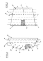
- the principal wing V1 ( Figure 1), that is to say that of which the central part 3 is intended to surround the right liver, is in the shape of an isosceles trapezium.
- its longer base 2 constitutes the first transverse edge intended to be fixed on the falciform ligament
- the shorter base 2 ⁇ constitutes the second transverse edge intended to be bent back on itself in the form of two segments 5 and 5 ⁇ .
- the two segments 5 and 5 ⁇ are symmetrical with respect to the bisector of the two bases of the trapezium.
- the longer base 2 has, preferably, a length between 40 and 50 cm, the ideal dimension being approximately 44 cm.
- the height of this trapezium, between 25 and 35 cm, is, preferably, approximately 30 cm.
- the shorter base 2 ⁇ has a length between 28 and 38 cm, and is preferably approximately 33 cm.
- the two lateral edges 1 and 1 ⁇ corresponding to the two non parallel sides of the trapezium, have a length between 21 and 41 cm, equal preferably to approximately 31 cm.
- the auxiliary wing V2 ( Figure 2), that is to say that of which the central part 31 is intended to surround the left liver, is preferably of convex pentagonal shape of which a segment 21, longer than the others, represents a first transverse edge, that is to say that which is intended to be fixed on the falciform ligament.
- This first transverse edge 21 measures between 45 and 55 cm, and is preferably approximately 50 cm long.
- the pentagon has symmetry with respect to the bisector of this first side 21.
- the bisector of which the length is between 20 and 26 cm, preferably measures approximately 21 cm.
- the two lateral edges 11 and 11 ⁇ intended to be attached to each other, have a length between 11 and 21 cm, which is preferably equal to 16 cm.
- the second transverse edge 21 ⁇ intended to be bent back on itself, it is in the form of two symmetrical segments 51 and 51 ⁇ , each of these segments measuring between 16 and 26 cm, preferably 21 cm.
- V1 and auxiliary V2 wings have been shown on the same sheet, at the same scale, and opposite to each other, in a manner to represent the way they are arranged on the liver, when positioned in a prosthesis according to the invention.
- the mesh of the constituent network of each of the two wings is shown partially at 16, but of course the entire wings are of a material having a mesh of this type.
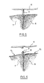
- Figures 3 and 7 show respectively the front and rear faces of the liver.
- the falciform ligament 9 connects the front face of the liver to the diaphragm 11 and thus to the abdominal wall as is shown schematically in Figure 5 (cross-section V-V).
- the triangular 13 and coronary 14 ligaments constitute a conjunctive tissue connecting the rear face of the liver to the diaphragm.
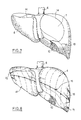
- Figures 4 and 8 show the front and rear faces of the liver respectively, these faces being covered by the prosthesis according to the present invention.
- the fixing of the first transverse edge 2,21 on the falciform ligament 9 can be made by means of clips or of whippings 12 after cutting of the said ligament as shown in Figure 6.
- This first transverse edge 2,21 being fixed, the right liver and the left liver, respectively, are surrounded and the two lateral edges 1 and 1 ⁇ , 11 and 11 ⁇ , of the prosthesis are fixed to each other.
- This fixing can also be made by means of clips of whippings.
- the prosthesis according to the present invention comprises transverse rows of surgical filaments 4,41, passed into the wing. These filaments are principally intended to compress the hepatic lobe after surrounding and tightening. If need be, the filaments can also be used to attach the two lateral edges 1 and 1 ⁇ , 11 and 11 ⁇ to each other.
- the filaments 4 are arranged parallel to the two bases 2 and 2 ⁇ of the trapezium ( Figure 1).
- these filaments 41 are arranged: - parallel to the first transverse edge 21 in a corresponding zone of the auxiliary win g V2, that is to say the zone close to the said first transverse edge 21, - parallel to each of the two segments 51 and 51 ⁇ forming the second transverse edge 21 ⁇ in the part intended to surround the edge of the left liver ( Figure 2).
- the filaments are advantageously placed on the prosthesis by the manufacturer of the prosthesis (and not by the surgeon).
- the useful network of the prosthesis according to the invention has "ladderproof" mesh when they are crossed by these surgical filaments.
- These filaments 4 and 41 are arranged at variable intervals between 2 and 12 cm, preferably 5 to 6 cm.
- filaments are used of which the colour permits them to be easily visible when they are positioned on an organ which is bleeding, such as violet or colourless, and, for easy manipulation, the colour of these filaments alternate.
- These filaments are intended to be knotted to each other, on positioning of the prosthesis ( Figure 8).
- Simple knots 15 can be made or slip knots, these latter permitting progressive tightening of the perihepatic prosthesis around the liver. These filaments are simply passed across the meshes of the network and, for rapid manipulation, are knotted together at their exits from the network, before use of the prosthesis.
- the prosthesis according to the present invention preferably has a colour adapted to its use such as its natural colour.
- each of the wings V1 and V2 can be positioned independently of the other.
- the positioning of the principal wing V1 will preferably be carried out according to the invention in the following manner:
- the surgeon slides the central part 3 of the principal wing V1 under the right liver 7, so that the longer base 2 is at the centre of the liver. He fixes this first transverse edge 2 along the length of the falciform ligament 9 by means of clips 12, and then surrounds the right liver 7 with the central part 3. He provisionally attaches the lateral edges 1 and 1 ⁇ to each other by means of surgical pincers. Then he turns back on itself the second transverse edge 2 ⁇ in the form of two symmetrical segments 5 and 5 ⁇ which he attaches to each other provisionally with surgical pincers. The right liver 7 is thus immediately haemostasised.
- the two lateral edges 1 and 1 ⁇ of the principal wing are thus definitively attached to each other.
- the two symmetrical segments 5 and 5 ⁇ comprising the second transverse edge 2 ⁇ they are definitively fixed to each other by means of surgical whippings or clips.
- the positioning of the auxiliary wing V2 is then carried out in a similar manner.
- the prosthesis according to the present invention acts for approximately two to three weeks after which it is progressively reabsorbed. Now, three or four days is sufficient for a haemostasia of the liver. The resistance of the network used is thus largely sufficient for permitting the regeneration of the hepatic tissues.
Abstract
Description
- The present invention relates to a perihepatic prosthesis particularly useful for treatment of mechanical lesions of the liver caused by shocks. This type of traumatism is the more frequent because the liver is the most voluminous organ of the body and because of this it is more at risk than the other internal parts of the body.
- It is known that the liver usually contains about 60% of its own weight in blood. This high percentage explains the urgency of treatment on wounding of this organ. Now, the connective capsule surrounding the liver, or Glisson capsule, is friable. It is thus quickly torn on sudden occurrence of a traumatism. The liver when exposed is very fragile despite its firm consistency; wounded, it bleeds rapidly and profusely. Only a small time is required for emptying the liver of its contents of blood and, without a rapid surgical operation, the liver rapidly loses its functional character.
- Further, the liver, because of the multiplicity of its functions, is an organ of such importance that its ineffectiveness rapidly leads to death of the individual.
- At present, surgeons are ill equipped for combatting hepatic haemorrhages, although they are more and more successful in combatting haemorrhages of other essential organs such as the kidney or spleen.
- It has already been proposed, for example, to use a knitted surgical mesh for preparation of a pad device intended for repair of injured organs such as the liver (see the specification of European Patent Application No. EP-A-0 159 502).
- Now any possible surgical haemostasia of this type is hampered because of the physiological and anatomical peculiarities of the liver which lead to particular problems.
- The physiological particularities of the liver are connected to the multiplicity of its functions: First, the liver is the organ producing bile. This latter is led via hepatic canals to the gall bladder, the storage organ intimately adhering onto the inner surface of the liver. Further, the liver is the site of a complex and important array of arteries and veins:
- oxygenated blood, coming from the aortic artery irrigates the liver via the hepatic artery which divides into two branches,
- the venous blood coming from all parts of the abdominal cavity is brought together in the portal vein which divides in the liver; thus all the abdominal venous blood passes through the liver,
- finally, three supra-hepatic veins lead the blood to the lower vena cava which rejoins the right heart. - This abundance of liquid circulating in the liver, arterial blood, abdominal venous blood, hepatic venous blood, bile, explains the seriousness of hepatic laceration.
- Surgeons have tried up to now to carry out local compressions for checking haemmorrhages. Not only are these local compressions insufficient in the case of a significant lesion but also they can aggravate hepatic traumatisms.
- In effect, it is necessary, for maintaining compresses in place for several days, to fix them by various means, particularly filaments or ribbons. These small scale systems very often generate cuts, aggravating the haemorrhage, or ischaemias hindering the return of tissues.
- In any case, none of the systems known at present permit rapid and reliable operation which is indispensable in the case of hepatic traumatisms.
- A tempting solution, known for the kidney and the spleen for permitting rapid and efficient haemostasia of the organ, resides in complete wrapping, holding the organ solidly but without compressing it and thus hindering the blood from flowing whilst permitting the regeneration of the tissues.
- But the anatomy of the liver a priori renders this solution impractical. In effect, whilst it is easy to wrap a round or tubular shape such as the kidney or the spleen, the asymmetric and irregular shape of the liver renders wrapping impossible. To its asymmetric form, is to be added the fact that the liver is not an organ isolated from others in the abdomen, being on the contrary solidly held in place, and connected to part of the diaphragm by:-
- the lower vena cava, a sort of large fastening column for this organ,
- the falciform ligament or suspension ligament which connects the upper face of the liver to the diaphragm and to the abdominal wall, and divides this organ into a right lobe and left lobe,
- triangular or coronary ligaments on the rear face of the liver which connect this to the lower face of the diaphragm. - This is why the known solution of wrapping is not applicable as such in the case of the liver.
- The present invention proposes a new prosthesis permitting by its own structure provision of such a wrapping profitting from the anatomical particularities of the liver which appear to the man skilled in the art as insurmountable obstacles.
- More precisely, the present invention proposes a perihepatic prosthesis provided in biodegradable supple surgical material having at least one wing constituted by a central part intended to surround a lobe of the liver, and by a peripheral fixing part, the said peripheral part having a first transverse edge intended to be fixed on the preliminarily sectioned falciform ligament.
- This peripheral part is thus able to hold the wing around the lobe whilst fastening it to the preliminarily sectioned falciform ligament.
- Preferably, the peripheral part comprises in addition to this first transverse edge intended to be fixed on the falciform ligament:
- a second transverse edge, opposite from the first, able to be bent back on itself in the form of two symmetric segments, the two symmetric segments being intended to be attached to each other,
- two lateral edges opposite each other, connecting the two transverse edges, and intended to be attached to each other. - Preferably, also, the prosthesis comprises a wing (a principal wing) intended for the right hepatic lobe and a wing (an auxiliary wing) intended for the left hepatic lobe.
- Such a structure is particularly suitable for responding to the problems posed.
- As previously mentioned, the falciform ligament which is found on the upper surface of the liver is an aponeurotic limit separating the two lobes of the liver: the right lobe, so voluminous that it will be designated by the term "right liver" in the rest of the description; the left lobe, much smaller, called the "left liver" below. Now, it has been noticed that, surprisingly, this falciform ligament, as well as the triangular and coronary ligaments, are in fact only embryonic residues, not determinative of the position of the liver. When these filaments are cut, the liver remains in position and then becomes an organ anatomically isolated from the others, and "fastened" as it were at a large column which is constituted by the lower vena cava.
- The applicant has realised that one can thus get round the anatomical problems (the asymmetric shape) and the physiological problems of the liver by positioning a prosthesis having a principal wing and/or an auxiliary wing which is fixed on the preliminarily sectioned falciform ligament, each of the two wings being able to be positioned independently of the other.
- This ligament proves to constitute, after its separation by cutting from the diaphragm, a sort of band able to serve as an anchorage for the prosthesis according to the invention.
- A major physiological problem is also surmounted, according to the invention, because the bile duct and biliary canals are covered up by the principal wing which thus avoids the bile spilling into the abdomen and permits the regeneration of the tissues constituting the gall bladder and biliary canals, often injured in a hepatic traumatism.
- The prosthesis according to the present invention can be provided in many surgical materials, but preferably, it is provided in a supple and biodegradable material of the tisssue type or knitted which will be designated by "network" in the rest of the description.
- By "network" is intended any product having a generally similar structure to that of a gauze, obtained by assembly of filaments which will advantageously be of the same nature as the ligature or suture filaments usually used in surgery, the assembly of these filaments being able to be carried out by any known means such as plaiting, weaving, assembly by knitting or crochet for example.
- Such networks find their applications amongst others in the treatment of large visceral exposures for which they permit the keeping alive of organs or in the conservation treatment of traumatic kidneys and spleens.
- These networks have generally satisfactory qualities of tolerance by the body, mechanical strength and speed of reabsorption. Further, the permeability of the absorbable network positioned for efficaceously containing the organs, constitutes a further asset since it permits the draining of serosities and excretion products normally flowing from a newly treated wound.
- Finally, the mesh of the network used according to the present invention is sufficiently resistant to be able to be fixed on the falciform ligament without it being necessary for it to be covered up by reinforcements in this area.
- In accordance with a preferred embodiment of the invention, the surgical material consists of a network of reabsorbable synthetic filaments based on a polymer of glycolic acid.
- In accordance with a preferred embodiment of the invention, the reabsorbable synthetic filaments of the said network are of a copolymer of glycolic acid and lactic acid. Preferably there will be used a VICRYL (Registered Trade Mark) network - polyglactine 910 which is a copolymer having approximately 90% of glycolic acid and approximately 10% of lactic acid.
- Each of the wings of the prosthesis according to the invention is preferably of the form adapted to the hepatic lobe for which it is intended. Preferably also, each of the wings has standard dimensions able to be adapted to individual variations, the dimensions of the liver varying of course from one individual to another.
- The shapes and dimensions of the prosthesis according to the present invention as well as the method for positioning one or other of the constituent wings of the prosthesis will appear from the following description and accompanying drawings. In the accompanying drawings:-
- - Figure 1 shows the principal wing laid flat;
- - Figure 2 shows the auxiliary wing also laid flat;
- - Figure 3 shows the front face of the liver;
- - Figure 4 shows the front face of the liver covered up by the perihepatic prosthesis according to the invention;
- - Figure 5 shows a cross-section on line V-V of Figure 3, in which is partially shown the diaphragm which is not visible in Figure 3;
- - Figure 6 shows a cross-section on line VI-VI of Figure 4 in which is partially shown the diaphragm not visible in Figure 4;
- - Figure 7 shows the rear face of the liver;
- - Figure 8 shows the rear face of the liver covered up by the perihepatic prosthesis according to the invention.
- The prosthesis of Figure 1 and 2 represents a preferred embodiment of the invention.
- The principal wing V₁ (Figure 1), that is to say that of which the
central part 3 is intended to surround the right liver, is in the shape of an isosceles trapezium. In its peripheral part, itslonger base 2 constitutes the first transverse edge intended to be fixed on the falciform ligament, and the shorter base 2ʹ constitutes the second transverse edge intended to be bent back on itself in the form of twosegments 5 and 5ʹ. The twosegments 5 and 5ʹ are symmetrical with respect to the bisector of the two bases of the trapezium. Thelonger base 2 has, preferably, a length between 40 and 50 cm, the ideal dimension being approximately 44 cm. The height of this trapezium, between 25 and 35 cm, is, preferably, approximately 30 cm. The shorter base 2ʹ has a length between 28 and 38 cm, and is preferably approximately 33 cm. - The two
lateral edges 1 and 1ʹ, corresponding to the two non parallel sides of the trapezium, have a length between 21 and 41 cm, equal preferably to approximately 31 cm. - The auxiliary wing V₂ (Figure 2), that is to say that of which the
central part 31 is intended to surround the left liver, is preferably of convex pentagonal shape of which asegment 21, longer than the others, represents a first transverse edge, that is to say that which is intended to be fixed on the falciform ligament. This firsttransverse edge 21 measures between 45 and 55 cm, and is preferably approximately 50 cm long. The pentagon has symmetry with respect to the bisector of thisfirst side 21. The bisector, of which the length is between 20 and 26 cm, preferably measures approximately 21 cm. The twolateral edges 11 and 11ʹ intended to be attached to each other, have a length between 11 and 21 cm, which is preferably equal to 16 cm. - As regards the second transverse edge 21ʹ, intended to be bent back on itself, it is in the form of two
symmetrical segments 51 and 51ʹ, each of these segments measuring between 16 and 26 cm, preferably 21 cm. - The principal V₁ and auxiliary V₂ wings have been shown on the same sheet, at the same scale, and opposite to each other, in a manner to represent the way they are arranged on the liver, when positioned in a prosthesis according to the invention.
- The mesh of the constituent network of each of the two wings is shown partially at 16, but of course the entire wings are of a material having a mesh of this type.
- Figures 3 and 7 show respectively the front and rear faces of the liver.
- In these Figures, there is schematically shown the
left 8 and right 7 lobes of the liver, thelower vena cava 6 and thegall bladder 10. - The
falciform ligament 9 connects the front face of the liver to thediaphragm 11 and thus to the abdominal wall as is shown schematically in Figure 5 (cross-section V-V). - The triangular 13 and coronary 14 ligaments constitute a conjunctive tissue connecting the rear face of the liver to the diaphragm.
- Figures 4 and 8 show the front and rear faces of the liver respectively, these faces being covered by the prosthesis according to the present invention.
- For positioning the prosthesis according to the present invention, one can use a variety of surgical fixing means. In particular, the fixing of the first
transverse edge falciform ligament 9 can be made by means of clips or ofwhippings 12 after cutting of the said ligament as shown in Figure 6. This firsttransverse edge lateral edges 1 and 1ʹ, 11 and 11ʹ, of the prosthesis are fixed to each other. This fixing can also be made by means of clips of whippings. Preferably the prosthesis according to the present invention comprises transverse rows ofsurgical filaments lateral edges 1 and 1ʹ, 11 and 11ʹ to each other. - In the case of the principal wing, the
filaments 4 are arranged parallel to the twobases 2 and 2ʹ of the trapezium (Figure 1). In the case of the auxiliary wing V₂, thesefilaments 41 are arranged:
- parallel to the firsttransverse edge 21 in a corresponding zone of the auxiliary win g V₂, that is to say the zone close to the said firsttransverse edge 21,
- parallel to each of the twosegments 51 and 51ʹ forming the second transverse edge 21ʹ in the part intended to surround the edge of the left liver (Figure 2). The filaments are advantageously placed on the prosthesis by the manufacturer of the prosthesis (and not by the surgeon). - The useful network of the prosthesis according to the invention has "ladderproof" mesh when they are crossed by these surgical filaments. These
filaments Simple knots 15 can be made or slip knots, these latter permitting progressive tightening of the perihepatic prosthesis around the liver. These filaments are simply passed across the meshes of the network and, for rapid manipulation, are knotted together at their exits from the network, before use of the prosthesis. - The prosthesis according to the present invention preferably has a colour adapted to its use such as its natural colour.
- The positioning of the prosthesis will be easy to understand with reference to the accompanying drawings.
- It has already been mentioned above that each of the wings V₁ and V₂ can be positioned independently of the other.
- Thus, by way of example, the positioning of the principal wing V₁ will preferably be carried out according to the invention in the following manner:
- After disengaging the liver from the surrounding organs by cutting of the falciform 9, triangular 13 and coronary 14 ligaments, the surgeon slides the
central part 3 of the principal wing V₁ under theright liver 7, so that thelonger base 2 is at the centre of the liver. He fixes this firsttransverse edge 2 along the length of thefalciform ligament 9 by means ofclips 12, and then surrounds theright liver 7 with thecentral part 3. He provisionally attaches thelateral edges 1 and 1ʹ to each other by means of surgical pincers. Then he turns back on itself the second transverse edge 2ʹ in the form of twosymmetrical segments 5 and 5ʹ which he attaches to each other provisionally with surgical pincers. Theright liver 7 is thus immediately haemostasised. - Then the surgeon knots one at a time by
simple knots 15, thesurgical filaments 4 preliminarily threaded in the network. The twolateral edges 1 and 1ʹ of the principal wing are thus definitively attached to each other. As regards the twosymmetrical segments 5 and 5ʹ comprising the second transverse edge 2ʹ, they are definitively fixed to each other by means of surgical whippings or clips. The positioning of the auxiliary wing V₂ is then carried out in a similar manner. - Once in position, the prosthesis according to the present invention acts for approximately two to three weeks after which it is progressively reabsorbed. Now, three or four days is sufficient for a haemostasia of the liver. The resistance of the network used is thus largely sufficient for permitting the regeneration of the hepatic tissues.
Claims (11)
at least one wing constituted of a central part intended to surround a hepatic lobe of the liver and
a peripheral fixing part comprising a first transverse edge intended to be fixed on a preliminarily sectioned falciform ligament of the said liver.
- a second transverse edge oppo site said first transverse edge and able to be bent back on itself in the form of two symmetric segments, the two symmetric segments being intended to be attached to each other,
- two lateral edges opposite each other and connecting said first and second transverse edges and intended to be attached to each other.
base between 40 and 50 cm,
base between 28 and 38 cm,
height between 25 and 35 cm.
- length of said first transverse edge between 45 and 55 cm,
- a length of each of said two segments adjacent each other constituting said second transverse edge between 16 and 26 cm,
- length of each of said two lateral edges between 11 and 21 cm.
Applications Claiming Priority (2)
| Application Number | Priority Date | Filing Date | Title |
|---|---|---|---|
| FR8614312A FR2605214B1 (en) | 1986-10-15 | 1986-10-15 | PERIHEPATIC PROSTHESIS |
| FR8614312 | 1986-10-15 |
Publications (2)
| Publication Number | Publication Date |
|---|---|
| EP0265157A1 true EP0265157A1 (en) | 1988-04-27 |
| EP0265157B1 EP0265157B1 (en) | 1992-12-30 |
Family
ID=9339867
Family Applications (1)
| Application Number | Title | Priority Date | Filing Date |
|---|---|---|---|
| EP87309058A Expired EP0265157B1 (en) | 1986-10-15 | 1987-10-14 | Perihepatic prosthesis |
Country Status (6)
| Country | Link |
|---|---|
| US (1) | US4878890A (en) |
| EP (1) | EP0265157B1 (en) |
| JP (1) | JP2567419B2 (en) |
| CA (1) | CA1297641C (en) |
| DE (1) | DE3783317T2 (en) |
| FR (1) | FR2605214B1 (en) |
Cited By (4)
| Publication number | Priority date | Publication date | Assignee | Title |
|---|---|---|---|---|
| WO1993010731A1 (en) * | 1991-12-06 | 1993-06-10 | Kensey Nash Corporation | Pads, methods of making, and methods of use for wound dressing, surgical reinforcement and hemostasis promotion |
| WO2002007648A1 (en) * | 2000-07-25 | 2002-01-31 | C.R. Bard, Inc. | Implantable prosthesis |
| WO2002019945A3 (en) * | 2000-09-07 | 2002-05-10 | American Med Syst | Coated sling material |
| US6592515B2 (en) | 2000-09-07 | 2003-07-15 | Ams Research Corporation | Implantable article and method |
Families Citing this family (67)
| Publication number | Priority date | Publication date | Assignee | Title |
|---|---|---|---|---|
| US5069660A (en) * | 1988-12-09 | 1991-12-03 | Grantham David S | Urethra prosthetic for relieving prostatic problems |
| US5186711A (en) * | 1989-03-07 | 1993-02-16 | Albert Einstein College Of Medicine Of Yeshiva University | Hemostasis apparatus and method |
| US5143082A (en) * | 1991-04-03 | 1992-09-01 | Ethicon, Inc. | Surgical device for enclosing an internal organ |
| US5380329A (en) * | 1992-07-28 | 1995-01-10 | Dental Marketing Specialists, Inc. | Bone augmentation method and apparatus |
| US5279539A (en) * | 1992-08-17 | 1994-01-18 | Ethicon, Inc. | Drawstring surgical pouch and method of use for preventing ovarian adhesions |
| US6123662A (en) | 1998-07-13 | 2000-09-26 | Acorn Cardiovascular, Inc. | Cardiac disease treatment and device |
| US5702343A (en) | 1996-10-02 | 1997-12-30 | Acorn Medical, Inc. | Cardiac reinforcement device |
| FR2754705B1 (en) * | 1996-10-18 | 1998-12-18 | Cogent Sarl | ANATOMICAL PROSTHESIS FOR THE REPAIR OF HERNIA BY LAPAROSCOPIC OR OPEN ROUTE |
| EP0991373B1 (en) | 1997-06-21 | 2004-09-15 | Acorn Cardiovascular, Inc. | Bag for at least partially enveloping a heart |
| US6085754A (en) * | 1998-07-13 | 2000-07-11 | Acorn Cardiovascular, Inc. | Cardiac disease treatment method |
| US6587734B2 (en) | 1998-11-04 | 2003-07-01 | Acorn Cardiovascular, Inc. | Cardio therapeutic heart sack |
| US6169922B1 (en) | 1998-11-18 | 2001-01-02 | Acorn Cardiovascular, Inc. | Defibrillating cardiac jacket with interwoven electrode grids |
| US6230714B1 (en) | 1998-11-18 | 2001-05-15 | Acorn Cardiovascular, Inc. | Cardiac constraint with prior venus occlusion methods |
| US6155972A (en) * | 1999-02-02 | 2000-12-05 | Acorn Cardiovascular, Inc. | Cardiac constraint jacket construction |
| US6173206B1 (en) | 1999-05-07 | 2001-01-09 | Ethicon, Inc. | Temporary pacing wire anchor |
| US6241654B1 (en) | 1999-07-07 | 2001-06-05 | Acorn Cardiovasculr, Inc. | Cardiac reinforcement devices and methods |
| US6193648B1 (en) | 1999-09-21 | 2001-02-27 | Acorn Cardiovascular, Inc. | Cardiac constraint with draw string tensioning |
| US6174279B1 (en) | 1999-09-21 | 2001-01-16 | Acorn Cardiovascular, Inc. | Cardiac constraint with tension indicator |
| US6179791B1 (en) | 1999-09-21 | 2001-01-30 | Acorn Cardiovascular, Inc. | Device for heart measurement |
| US6702732B1 (en) | 1999-12-22 | 2004-03-09 | Paracor Surgical, Inc. | Expandable cardiac harness for treating congestive heart failure |
| US6293906B1 (en) * | 2000-01-14 | 2001-09-25 | Acorn Cardiovascular, Inc. | Delivery of cardiac constraint jacket |
| DE60124872T2 (en) | 2000-03-10 | 2007-06-14 | Paracor Medical, Inc., Los Altos | EXPANDABLE HEARTS BAG FOR THE TREATMENT OF CONGESTIVE HEART FAILURE |
| US6425856B1 (en) | 2000-05-10 | 2002-07-30 | Acorn Cardiovascular, Inc. | Cardiac disease treatment and device |
| US20050095268A1 (en) * | 2000-06-12 | 2005-05-05 | Acorn Cardiovascular, Inc. | Cardiac wall tension relief with cell loss management |
| US6902522B1 (en) | 2000-06-12 | 2005-06-07 | Acorn Cardiovascular, Inc. | Cardiac disease treatment and device |
| US6730016B1 (en) * | 2000-06-12 | 2004-05-04 | Acorn Cardiovascular, Inc. | Cardiac disease treatment and device |
| US6951534B2 (en) * | 2000-06-13 | 2005-10-04 | Acorn Cardiovascular, Inc. | Cardiac support device |
| US6482146B1 (en) * | 2000-06-13 | 2002-11-19 | Acorn Cardiovascular, Inc. | Cardiac disease treatment and device |
| US6572533B1 (en) | 2000-08-17 | 2003-06-03 | Acorn Cardiovascular, Inc. | Cardiac disease treatment and device |
| US6564094B2 (en) | 2000-12-22 | 2003-05-13 | Acorn Cardiovascular, Inc. | Cardiac disease treatment and device |
| US6575921B2 (en) | 2001-02-09 | 2003-06-10 | Acorn Cardiovascular, Inc. | Device for heart measurement |
| DK1423066T3 (en) | 2001-09-07 | 2008-11-17 | Mardil Inc | Method and apparatus for external cardiac stabilization |
| US6723041B2 (en) | 2001-09-10 | 2004-04-20 | Lilip Lau | Device for treating heart failure |
| JP2005507706A (en) | 2001-10-31 | 2005-03-24 | パラコー メディカル インコーポレイテッド | Heart failure treatment device |
| US7174896B1 (en) | 2002-01-07 | 2007-02-13 | Paracor Medical, Inc. | Method and apparatus for supporting a heart |
| US7022063B2 (en) | 2002-01-07 | 2006-04-04 | Paracor Medical, Inc. | Cardiac harness |
| US20030229260A1 (en) * | 2002-06-05 | 2003-12-11 | Acorn Cardiovascular, Inc. | Cardiac support device with tension indicator |
| US20030229261A1 (en) * | 2002-06-06 | 2003-12-11 | Acorn Cardiovascular, Inc. | Cardiac support devices and methods of producing same |
| US6682475B2 (en) | 2002-06-11 | 2004-01-27 | Acorn Cardiovascular, Inc. | Tension indicator for cardiac support device and method therefore |
| US7485089B2 (en) | 2002-09-05 | 2009-02-03 | Paracor Medical, Inc. | Cardiac harness |
| US7229405B2 (en) | 2002-11-15 | 2007-06-12 | Paracor Medical, Inc. | Cardiac harness delivery device and method of use |
| CA2504555C (en) | 2002-11-15 | 2012-09-04 | Paracor Medical, Inc. | Cardiac harness delivery device |
| US7736299B2 (en) | 2002-11-15 | 2010-06-15 | Paracor Medical, Inc. | Introducer for a cardiac harness delivery |
| US7291105B2 (en) | 2003-07-10 | 2007-11-06 | Paracor Medical, Inc. | Self-anchoring cardiac harness |
| US7235042B2 (en) * | 2003-09-16 | 2007-06-26 | Acorn Cardiovascular, Inc. | Apparatus and method for applying cardiac support device |
| US7158839B2 (en) | 2003-11-07 | 2007-01-02 | Paracor Medical, Inc. | Cardiac harness for treating heart disease |
| US7155295B2 (en) | 2003-11-07 | 2006-12-26 | Paracor Medical, Inc. | Cardiac harness for treating congestive heart failure and for defibrillating and/or pacing/sensing |
| EP1703854A1 (en) | 2004-01-12 | 2006-09-27 | Paracor Medical, Inc. | Cardiac harness having interconnected strands |
| US7587247B2 (en) | 2005-08-01 | 2009-09-08 | Paracor Medical, Inc. | Cardiac harness having an optimal impedance range |
| CN107358595B (en) * | 2005-11-01 | 2021-09-03 | 美国医软科技公司 | Method and system for lobe segmentation and preoperative surgical planning |
| US7727142B2 (en) * | 2006-03-03 | 2010-06-01 | Acorn Cardiovascular, Inc. | Delivery tool for cardiac support device |
| US20070208217A1 (en) | 2006-03-03 | 2007-09-06 | Acorn Cardiovascular, Inc. | Self-adjusting attachment structure for a cardiac support device |
| US20070270882A1 (en) | 2006-05-19 | 2007-11-22 | Acorn Cardiovascular, Inc. | Pericardium management method for intra-pericardial surgical procedures |
| US20080004488A1 (en) | 2006-06-29 | 2008-01-03 | Acorn Cardiovascular, Inc. | Low friction delivery tool for a cardiac support device |
| US7651462B2 (en) | 2006-07-17 | 2010-01-26 | Acorn Cardiovascular, Inc. | Cardiac support device delivery tool with release mechanism |
| US7641608B1 (en) | 2006-09-26 | 2010-01-05 | Acorn Cardiovascular, Inc. | Sectional cardiac support device and method of delivery |
| US8192351B2 (en) | 2007-08-13 | 2012-06-05 | Paracor Medical, Inc. | Medical device delivery system having integrated introducer |
| US8092363B2 (en) | 2007-09-05 | 2012-01-10 | Mardil, Inc. | Heart band with fillable chambers to modify heart valve function |
| US11854427B2 (en) | 2010-06-30 | 2023-12-26 | Strategic Operations, Inc. | Wearable medical trainer |
| US11495143B2 (en) | 2010-06-30 | 2022-11-08 | Strategic Operations, Inc. | Emergency casualty care trainer |
| US11688303B2 (en) | 2010-06-30 | 2023-06-27 | Strategic Operations, Inc. | Simulated torso for an open surgery simulator |
| US10360817B2 (en) * | 2010-06-30 | 2019-07-23 | Stuart Charles Segall | Wearable partial task surgical simulator |
| CA2898620C (en) | 2012-10-12 | 2022-10-04 | Mardil, Inc. | Cardiac treatment system and method |
| USD717954S1 (en) | 2013-10-14 | 2014-11-18 | Mardil, Inc. | Heart treatment device |
| US20150134077A1 (en) * | 2013-11-08 | 2015-05-14 | Ethicon Endo-Surgery, Inc. | Sealing materials for use in surgical stapling |
| EP3025652A1 (en) * | 2014-11-28 | 2016-06-01 | Luc Joyeux | Biomedical device for watertight sealing an opening |
| CN112105305A (en) * | 2018-03-23 | 2020-12-18 | 多伦多统一健康中心 | Devices, methods, and kits for perihepatic tamponade |
Citations (3)
| Publication number | Priority date | Publication date | Assignee | Title |
|---|---|---|---|---|
| US3124136A (en) * | 1964-03-10 | Method of repairing body tissue | ||
| EP0159502A2 (en) * | 1984-04-26 | 1985-10-30 | American Cyanamid Company | Absorbable surgical repair mesh |
| EP0194192A1 (en) * | 1985-02-22 | 1986-09-10 | Ethnor | Absorbable composite chirurgical material, method of preparation, resorbable prosthesis based on this material and use of this prosthesis |
Family Cites Families (6)
| Publication number | Priority date | Publication date | Assignee | Title |
|---|---|---|---|---|
| FR2224171B1 (en) * | 1973-04-09 | 1976-11-12 | Rhone Poulenc Ind | |
| US4033938A (en) * | 1974-01-21 | 1977-07-05 | American Cyanamid Company | Polymers of unsymmetrically substituted 1,4-dioxane-2,5-diones |
| US4428375A (en) * | 1982-02-16 | 1984-01-31 | Ellman Barry R | Surgical bag for splenorrhaphy |
| US4403604A (en) * | 1982-05-13 | 1983-09-13 | Wilkinson Lawrence H | Gastric pouch |
| US4655221A (en) * | 1985-05-06 | 1987-04-07 | American Cyanamid Company | Method of using a surgical repair mesh |
| US4693720A (en) * | 1985-09-23 | 1987-09-15 | Katecho, Incorporated | Device for surgically repairing soft tissues and method for making the same |
-
1986
- 1986-10-15 FR FR8614312A patent/FR2605214B1/en not_active Expired - Lifetime
-
1987
- 1987-10-13 US US07/108,385 patent/US4878890A/en not_active Expired - Lifetime
- 1987-10-13 CA CA000549160A patent/CA1297641C/en not_active Expired - Lifetime
- 1987-10-14 EP EP87309058A patent/EP0265157B1/en not_active Expired
- 1987-10-14 DE DE8787309058T patent/DE3783317T2/en not_active Expired - Lifetime
- 1987-10-15 JP JP62260759A patent/JP2567419B2/en not_active Expired - Lifetime
Patent Citations (3)
| Publication number | Priority date | Publication date | Assignee | Title |
|---|---|---|---|---|
| US3124136A (en) * | 1964-03-10 | Method of repairing body tissue | ||
| EP0159502A2 (en) * | 1984-04-26 | 1985-10-30 | American Cyanamid Company | Absorbable surgical repair mesh |
| EP0194192A1 (en) * | 1985-02-22 | 1986-09-10 | Ethnor | Absorbable composite chirurgical material, method of preparation, resorbable prosthesis based on this material and use of this prosthesis |
Cited By (14)
| Publication number | Priority date | Publication date | Assignee | Title |
|---|---|---|---|---|
| WO1993010731A1 (en) * | 1991-12-06 | 1993-06-10 | Kensey Nash Corporation | Pads, methods of making, and methods of use for wound dressing, surgical reinforcement and hemostasis promotion |
| US6610006B1 (en) | 2000-07-25 | 2003-08-26 | C. R. Bard, Inc. | Implantable prosthesis |
| WO2002007648A1 (en) * | 2000-07-25 | 2002-01-31 | C.R. Bard, Inc. | Implantable prosthesis |
| US7025063B2 (en) | 2000-09-07 | 2006-04-11 | Ams Research Corporation | Coated sling material |
| US6592515B2 (en) | 2000-09-07 | 2003-07-15 | Ams Research Corporation | Implantable article and method |
| US6884212B2 (en) | 2000-09-07 | 2005-04-26 | Ams Research Corporation | Implantable article and method |
| WO2002019945A3 (en) * | 2000-09-07 | 2002-05-10 | American Med Syst | Coated sling material |
| US7517313B2 (en) | 2000-09-07 | 2009-04-14 | Ams Research Corporation | Implantable article and method |
| US8147478B2 (en) | 2000-09-07 | 2012-04-03 | Ams Research Corporation | Coated sling material |
| US8702586B2 (en) | 2000-09-07 | 2014-04-22 | Ams Research Corporation | Implantable article and method |
| US8905912B2 (en) | 2000-09-07 | 2014-12-09 | Ams Research Corporation | Implantable article and method |
| US9022921B2 (en) | 2000-09-07 | 2015-05-05 | Ams Research Corporation | Implantable article and method |
| US9211177B2 (en) | 2000-09-07 | 2015-12-15 | Ams Research Corporation | Implantable article and method |
| US9987113B2 (en) | 2000-09-07 | 2018-06-05 | Astora Women's Health, Llc | Implantable article and method |
Also Published As
| Publication number | Publication date |
|---|---|
| DE3783317T2 (en) | 1993-05-13 |
| CA1297641C (en) | 1992-03-24 |
| US4878890A (en) | 1989-11-07 |
| FR2605214A1 (en) | 1988-04-22 |
| EP0265157B1 (en) | 1992-12-30 |
| JPS63102754A (en) | 1988-05-07 |
| FR2605214B1 (en) | 1992-01-10 |
| DE3783317D1 (en) | 1993-02-11 |
| JP2567419B2 (en) | 1996-12-25 |
Similar Documents
| Publication | Publication Date | Title |
|---|---|---|
| EP0265157B1 (en) | Perihepatic prosthesis | |
| Gundry et al. | Optimal preparation techniques for human saphenous vein grafts | |
| AU620182B2 (en) | Low molecular weight heparin, heparinoid and hexuronyl hexosaminoglycan sulfate containing adhesion prevention barrier and process | |
| Björkerud | Reaction of the aortic wall of the rabbit after superficial, longitudinal, mechanical trauma | |
| US4452245A (en) | Surgical mesh and method | |
| US4347847A (en) | Method of hernia repair | |
| US5007916A (en) | Method and material for prevention of surgical adhesions | |
| DE69629360T2 (en) | SURGICAL PROSTHESIS | |
| US7081135B2 (en) | Mastopexy stabilization apparatus and method | |
| US20100063472A1 (en) | Compositions and methods for improved occlusion of vascular defects | |
| EP0213563A2 (en) | Method and material for prevention of surgical adhesions | |
| DE2206144A1 (en) | COPOLYMERS ABSORBABLE BY LIVING MAMMALIAN TISSUES | |
| CN109561893A (en) | The tissue being used together with the fixed repair system of soft tissue with method enhances structure | |
| JP2012511955A (en) | Biocompatible fiber-based device for tissue-guided regeneration | |
| WO2010117908A1 (en) | Anisotropic reinforcement and related method thereof | |
| CN109009280A (en) | Tissue for the fixed repair system of soft tissue and method enhances tack | |
| Lehmann et al. | Internal-mammary coronary artery grafts: is their superiority also due to a basically intact endothelium? | |
| Sampson | Endometriosis following salpingectomy | |
| JP2637782B2 (en) | Resorbable surgical mesh and prosthesis manufactured therefrom | |
| Weinstein et al. | Resection and reconstruction of the mandible for removal of a central hemangioma | |
| JP2019514488A (en) | Implants and methods for the treatment of pelvic disease | |
| JPH11276572A (en) | Material for medical care made of poly(gamma-glutamic acid) salt complex | |
| O'Reilly et al. | Experimental arterial aneurysms: modification of the production technique | |
| Galvin | Mammary artery grafts: a new no-touch technique for anastomosis | |
| US20230212508A1 (en) | Adipose tissue regeneration base material |
Legal Events
| Date | Code | Title | Description |
|---|---|---|---|
| PUAI | Public reference made under article 153(3) epc to a published international application that has entered the european phase |
Free format text: ORIGINAL CODE: 0009012 |
|
| AK | Designated contracting states |
Kind code of ref document: A1 Designated state(s): DE GB |
|
| 17P | Request for examination filed |
Effective date: 19881019 |
|
| 17Q | First examination report despatched |
Effective date: 19910913 |
|
| GRAA | (expected) grant |
Free format text: ORIGINAL CODE: 0009210 |
|
| AK | Designated contracting states |
Kind code of ref document: B1 Designated state(s): DE GB |
|
| REF | Corresponds to: |
Ref document number: 3783317 Country of ref document: DE Date of ref document: 19930211 |
|
| PLBE | No opposition filed within time limit |
Free format text: ORIGINAL CODE: 0009261 |
|
| STAA | Information on the status of an ep patent application or granted ep patent |
Free format text: STATUS: NO OPPOSITION FILED WITHIN TIME LIMIT |
|
| 26N | No opposition filed | ||
| REG | Reference to a national code |
Ref country code: GB Ref legal event code: IF02 |
|
| PGFP | Annual fee paid to national office [announced via postgrant information from national office to epo] |
Ref country code: GB Payment date: 20061011 Year of fee payment: 20 |
|
| PGFP | Annual fee paid to national office [announced via postgrant information from national office to epo] |
Ref country code: DE Payment date: 20061012 Year of fee payment: 20 |
|
| REG | Reference to a national code |
Ref country code: GB Ref legal event code: PE20 |
|
| PG25 | Lapsed in a contracting state [announced via postgrant information from national office to epo] |
Ref country code: GB Free format text: LAPSE BECAUSE OF EXPIRATION OF PROTECTION Effective date: 20071013 |