EP0263687A2 - Spread spectrum communications systems and transmitters and receivers therefor - Google Patents
Spread spectrum communications systems and transmitters and receivers therefor Download PDFInfo
- Publication number
- EP0263687A2 EP0263687A2 EP87308871A EP87308871A EP0263687A2 EP 0263687 A2 EP0263687 A2 EP 0263687A2 EP 87308871 A EP87308871 A EP 87308871A EP 87308871 A EP87308871 A EP 87308871A EP 0263687 A2 EP0263687 A2 EP 0263687A2
- Authority
- EP
- European Patent Office
- Prior art keywords
- filter
- signal
- transmitter
- spread spectrum
- fir filter
- Prior art date
- Legal status (The legal status is an assumption and is not a legal conclusion. Google has not performed a legal analysis and makes no representation as to the accuracy of the status listed.)
- Granted
Links
Images


Classifications
-
- H—ELECTRICITY
- H04—ELECTRIC COMMUNICATION TECHNIQUE
- H04B—TRANSMISSION
- H04B1/00—Details of transmission systems, not covered by a single one of groups H04B3/00 - H04B13/00; Details of transmission systems not characterised by the medium used for transmission
- H04B1/69—Spread spectrum techniques
- H04B1/707—Spread spectrum techniques using direct sequence modulation
Definitions
- This invention relates to a spread spectrum communications system, more particularly to a system comprising a transmitter and a receiver linked by a communication channel and to transmitters and receivers adapted for use in such systems.
- SS communications techniques are used in mobile communications and satellite communications, because of security, resistance to jamming, and/or compatibility with other existing communications systems amongst others.
- Figure 2 shows a conventional baseband SS communications system with a transmitter 12 and a receiver 13 linked by a communication channel 6.
- the transmitter 12 comprises a data modulator 2 for modulating transmit data received from an input terminal 1, an SS code modulator 4 for modulating a spread spectrum (SS) code received from an input terminal 3, and a multiplier 5 for multiplying the output from the data modulator 2 and the output from the SS code modulator 4 together.
- the receiver 13 comprises an SS code modulator 8 for modulating an SS code received from an input terminal 7, a multiplier 9 for multiplying the signal received from the communication channel 6 and the output from the SS code modulator 8 together, an integrate-and-discharge filter 10, and an output terminal 11.
- a series of transmit data is input in sequence from the input terminal 1 and converted by the data modulator 2 to a transmit data signal.
- a spread spectrum code is input from the input terminal 3 and converted by the SS code modulator 4 to the SS signal.
- the transmit data signal and the SS signal are multiplied together in the multiplier 5 and the resulting output is sent on the communication channel 6.
- the receiver 13 performs the following process. First it receives a transmitted signal via the communication channel 6. It also inputs an SS code which is the same code as used in the transmitter. This SS code is converted by the SS code modulator 8 to exactly the same SS signal asused in the transmitter.
- the multiplier 9 multiplies the SS signals and transmitted signals together, and the resulting output is input to the integrate-and-discharge filter 10, the output from which is used to restore the original transmit data series.
- the invention aims to provide an improved SS communications system.
- the invention hence provides in a spread spectrum communications system comprising a transmitter which transmits a signal resulting from multiplication of a modulated transmit data signal and a modulated spread spectrum code, and a receiver, linked to the transmitter by a communication channel, which receives the signal transmitted from the transmitter and multiplies it by a modulated spread spectrum signal to restore the original transmit data, in which an FIR filter is inserted in the output section of the transmitter and a filter having a characteristic inverse to that of the FIR filter is inserted in the input section of the receiver.
- the means employed by this invention function as follows.
- the FIR filter functions to reduce the peaks of the power spectrum density of the transmitted signal, and to conceal the transmitted signal in the noise on the communication channel.
- the filter in the receiver functions to restore the signal received from the transmitter via the communication channel which has been distorted by the charactistic of the FIR filter, to the original signal j Jy application of the inverse characteristic.
- the invention also provides a transmitter and receiver adapted to function in the above communications network.
- FIG. 1A shows a block diagram of an embodiment of this invention and component elements labelled with the same reference numbers as in Figure 2 are numbered identically to the corresponding elements in Figure 2.
- the SS communications system of this invention comprises a transmitter 16 and a receiver 17 linked by a communication channel 6.
- the transmitter 16 comprises, in addition to the component elements of the transmitter 12 in Figure 2, an FIR (Finite Impulse Response) filter 15 connected to the input of the multiplier 9.
- FIR Finite Impulse Response
- FIG. 1B shows the internal structure of the FIR filter 14.
- the FIR filter 14 comprises delay elements 18-1, 18-2, ..., 18-N, multipliers 19-1, 19-2, ..., 19-N, an adder 20, an input terminal 21, and an output terminal 22.
- Figure 1C shows the internal structure of the IIR filter 15.
- the IIR filter 15 comprises an input terminal 23, an added 24, an output terminal 25, delay element 26-1, 26-2, ..., 26-N, and multipliers 27-1, 27-2, ..., 27-N.
- the transmit data signal b(t) and the SS signal a(t) are multiplied together in the multiplier 5, and the resulting output d(t) is input to the FIR filter 14.
- the output signal e(t) from this FIR filter 14 is sent on the communication channel 6.
- the transmit data signal d(t) is input at the input terminal 21.
- This transmit data signal d(t) is applied to the delay element 18-1, which delays it by a time T d .
- the transmit data signal d(t) is shifted successively by the delay elements 18-1, 18-2, ..., 18-N, each of which delays it by a time T d .
- the outputs d(t-T d ), d(t-2T d ), ..., d(t-NT d ) from the delay elements 18-1, 18-2, ..., 18-N are multiplied by A 1 , A 2 , ..., AN in the multipliers 19-1,19-2, ..., 19-N, and the outputs A 1 d(t-T d ), A 2 d(t-2T d ), ..., A N d(t-NT d ) from these multipliers are added to the transmit data d(t) in the adder 20.
- the resulting signal e(t) is sent through the output terminal 22 to the communication channel 6.
- the output signal r(t) from the Ilr filter 15 is multiplied in the multiplier 9 by the SS signal a(t), which is identical to the signal used in the transmitter and is described by Eq. (3).
- the signal a(t) is output from the SS code modulator 8, which inputs from the input terminal 7 an SS code (a 1 ) (identical to the code used in the transmitter) having period Nc.
- the output (t)a(t) from the multiplier 9 is fed to the integrate-and-discharge filter 10, the output from which is used to restore the original data series ⁇ b m ⁇ .
- the process performed by the IIR filter 15 will be explained with reference to Fig. 1 C.
- the signal r(t) is input at the input terminal 23.
- the outputs (t-T d ), (t-2T d ), ..., (t-NT d ) from the delay elements 26-1, 26-2, ..., 26-N at time t are multiplied by A 1 , A 2 , ..., AN in the multipliers 27-1, 27-2, ..., 27-N, and the outputs A 1 (t-T d ), A 2 (t-2T d ), ..., A N (t-NT d ) from these multipliers are added to the signal r(t) in the adder 24.
- the output signal (t) from the adder 24 is sent to the output terminal 25 and is also input to the delay element 26-1, so that as time t progresses the signal is shifted successively by the delay elements 26-1, 26-1, ..., 26-N.
- the operation of an embodiment of the present invention has been described. Next the operation of this embodiment will be analyzed. As already explained, the FIR filter 14 and the IIR filter 15 have the same order N.
- the delay time T d of the delay elements 18-1, 18-2, ..., 18-N in dthe FIR filter 14 is also equal to the delaytime T d of the delay elements 26-1, 26-2, ..., 26-N of the IIR filter 15.
- the coefficients A 1 , A 2 , ..., AN of the multipliers 19-1, 19-2, ..., 19-N of the FIR filter 14 are also designed to be identical to the coefficients A 1 , A 2 , ..., AN of the multipliers 27-1, 27-2, ..., 27-N of the IIR filter 15.
- the FIR filter 14 and IIR filter 15 are accordingingly inverse filters.
- the output signal m from the multiplier 9 corresponding to the transmitted data bm can be expressed as : where s,m and N,m are: (where E[.] denotes the set average), and asume that the noise n(t) on the communication channel is a white Gaussian noise with power spectrum density No/2. It follows that: where Sa(x) and S(1) (f) are given as below: The coefficients C 1,1 (k) are as follows: From the above, the signal-to-noise ratio (SNR) of the receiver 17 is:
- the order N, the delay time T d of the delay elements 18-1, 18-2, ..., 18-N and the delay elements 27-1, 27-2, ..., 27-N, and the multiplier coefficients A 1 , A 2 , ..., AN of the FIR filter 14 and IIR filter 15 used in this invention correspond to the order N, the sampling interval T d , and the coefficients An derived from the Yule-Walker equation for the AR model of the time series generated by the SS signal, and the FIR filter 14 and the IIR filter 15 are inversely related as seen above.
- IIR filter 15 in the receiver 17 in combination with the use of the FIR filter 14 in the transmitter 16 is advantageous in that the IIR filter 15 has the transfer function inverse to that of the FIR filter 14 if the coefficients A 1 to AN of the multipliers 27-1 to 27-N are given the same values as those of the multipliers 19-1 to 19-N.
- the IIR filter in the receiver can be replaced by an FIR filter.
- the coefficients of the multipliers of the FIR filter should be determined such that the transfer function of the FIR filter in the receiver is approximately, if not exactly, inverse to that of the FIR filter in the transmitter. To obtain the exactly inverse relationship between the transfer functions is difficult because the order N. (number of steps) in the FIR filter is finite.
- the signal e(t) output to the communication channel 6 by the SS communications system of this invention is more easily concealed by the noise n(t) on the communication channel than the signal d(t) output to the communication channel 6 by the SS communications system of the prior art.
- Fig. 5A through 5C show the power spectrum densities of the signals d(t) and e(t).
- Fig 5A shows the power spectrum density in the SS communications system of the prior art.
- Fig. 5B and 5C show the power spectrum density in the SS communications system of the present invention.
- the power spectrum density of the signal d(t) transmitted to the communication channel 6, given by Eq. (5), has comparatively low peak values (unlike the prior art, see Denshi Tsushin Gakkai Rombunshi (B), Vol. J66-B, 11 (November 1983), pp. 1362 - 1369). Interference with other existing communication systems is reduced. Using pulse detector receiving equipment, for example, it is comparatively difficult to intercept the transmission.
Abstract
Description
- This invention relates to a spread spectrum communications system, more particularly to a system comprising a transmitter and a receiver linked by a communication channel and to transmitters and receivers adapted for use in such systems.
- Spread spectrum (SS) communications techniques are used in mobile communications and satellite communications, because of security, resistance to jamming, and/or compatibility with other existing communications systems amongst others.
- Figure 2 shows a conventional baseband SS communications system with a
transmitter 12 and areceiver 13 linked by acommunication channel 6. Thetransmitter 12 comprises adata modulator 2 for modulating transmit data received from aninput terminal 1, anSS code modulator 4 for modulating a spread spectrum (SS) code received from aninput terminal 3, and amultiplier 5 for multiplying the output from thedata modulator 2 and the output from theSS code modulator 4 together. Thereceiver 13 comprises anSS code modulator 8 for modulating an SS code received from aninput terminal 7, amultiplier 9 for multiplying the signal received from thecommunication channel 6 and the output from theSS code modulator 8 together, an integrate-and-discharge filter 10, and anoutput terminal 11. A series of transmit data is input in sequence from theinput terminal 1 and converted by thedata modulator 2 to a transmit data signal. At the same time, a spread spectrum code is input from theinput terminal 3 and converted by theSS code modulator 4 to the SS signal. The transmit data signal and the SS signal are multiplied together in themultiplier 5 and the resulting output is sent on thecommunication channel 6. Next, thereceiver 13 performs the following process. First it receives a transmitted signal via thecommunication channel 6. It also inputs an SS code which is the same code as used in the transmitter. This SS code is converted by theSS code modulator 8 to exactly the same SS signal asused in the transmitter. Themultiplier 9 multiplies the SS signals and transmitted signals together, and the resulting output is input to the integrate-and-discharge filter 10, the output from which is used to restore the original transmit data series. - The invention aims to provide an improved SS communications system. The invention hence provides in a spread spectrum communications system comprising a transmitter which transmits a signal resulting from multiplication of a modulated transmit data signal and a modulated spread spectrum code, and a receiver, linked to the transmitter by a communication channel, which receives the signal transmitted from the transmitter and multiplies it by a modulated spread spectrum signal to restore the original transmit data, in which an FIR filter is inserted in the output section of the transmitter and a filter having a characteristic inverse to that of the FIR filter is inserted in the input section of the receiver.
- In a spread spectrum communications system structure according to this invention as above, the means employed by this invention function as follows. The FIR filter functions to reduce the peaks of the power spectrum density of the transmitted signal, and to conceal the transmitted signal in the noise on the communication channel. The filter in the receiver functions to restore the signal received from the transmitter via the communication channel which has been distorted by the charactistic of the FIR filter, to the original signaljJy application of the inverse characteristic. The invention also provides a transmitter and receiver adapted to function in the above communications network.
-
- Figure 1 A is a block diagram of an embodiment of the invention;
- Figure 1 B is a block diagram of an FIR filter used in Figure 1A;
- Figure 1C is a block diagram of the IIR filter used in Figure 1A;
- Figure 2 is a block diagram of a spread spectrum communications system of the prior art;
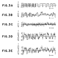
- Figure 3A through 3E and the Figure 4A through 4D shows signal waveforms at various points in the embodiment in Figure 1;
- Figure 5A through 5C describe the power spectrum density of the transmitted signal in the embodiment in Figure 1; and
- Figure 6 describes the effect of the FIR filter in suppressing peak values in the power spectrum of the transmitted signal in a system according to the invention.
- Figure 1A shows a block diagram of an embodiment of this invention and component elements labelled with the same reference numbers as in Figure 2 are numbered identically to the corresponding elements in Figure 2. The SS communications system of this invention comprises a
transmitter 16 and areceiver 17 linked by acommunication channel 6. Thetransmitter 16 comprises, in addition to the component elements of thetransmitter 12 in Figure 2, an FIR (Finite Impulse Response)filter 15 connected to the input of themultiplier 9. - Figure 1B shows the internal structure of the
FIR filter 14. As seen in Figure 1 B, theFIR filter 14 comprises delay elements 18-1, 18-2, ..., 18-N, multipliers 19-1, 19-2, ..., 19-N, anadder 20, aninput terminal 21, and anoutput terminal 22. Figure 1C shows the internal structure of theIIR filter 15. As seen in Figure 1C, theIIR filter 15 comprises aninput terminal 23, an added 24, anoutput terminal 25, delay element 26-1, 26-2, ..., 26-N, and multipliers 27-1, 27-2, ..., 27-N. The operation of an SS communications system with the above configuration will be described next. - First, the operation of the
transmitter 16 will be explained. A series of transmit data (bm) (where m = -∞, -1, 0, 1, ..., + ∞) is input in sequence from theinput terminal 1 to thetransmitter 16 and converted by thedata modulator 2 to the transmit data signal b(t) described earlier, where

input terminal 3 and converted by theSS code modulator 4 to an SS signal a(t):

multiplier 5, and the resulting output d(t)
FIR filter 14. The output signal e(t) from thisFIR filter 14 is sent on thecommunication channel 6. - The process performed by the
FIR filter 14 will be explained with reference to Fig. 1 B. At time t the transmit data signal d(t) is input at theinput terminal 21. This transmit data signal d(t) is applied to the delay element 18-1, which delays it by a time Td. At successive times t the transmit data signal d(t) is shifted successively by the delay elements 18-1, 18-2, ..., 18-N, each of which delays it by a time Td. At time t the outputs d(t-Td), d(t-2Td), ..., d(t-NTd) from the delay elements 18-1, 18-2, ..., 18-N are multiplied by A1, A2, ..., AN in the multipliers 19-1,19-2, ..., 19-N, and the outputs A1d(t-Td), A2d(t-2Td), ..., ANd(t-NTd) from these multipliers are added to the transmit data d(t) in theadder 20. The resulting signal e(t) is sent through theoutput terminal 22 to thecommunication channel 6. - Next the operation of the
receiver 17 will be described. The signal r(t) received from the transmitter via thecommunication channel 6 is input to theIIR filter 15. At this point the signal r(t) consists of the signal e(t) sent by thetransmitter 16 plus noise n(t) occurring on the communication channel 6:
r(t) = e(t) + n(t) (6) - Next the output signal r(t) from the
Ilr filter 15 is multiplied in themultiplier 9 by the SS signal a(t), which is identical to the signal used in the transmitter and is described by Eq. (3). The signal a(t) is output from theSS code modulator 8, which inputs from theinput terminal 7 an SS code (a1) (identical to the code used in the transmitter) having period Nc. The output(t)a(t) from the
multiplier 9 is fed to the integrate-and-discharge filter 10, the outputfrom which is used to restore the original data series {bm}. - The process performed by the
IIR filter 15 will be explained with reference to Fig. 1 C. At time t the signal r(t) is input at theinput terminal 23. The outputs(t-Td),(t-2Td), ...,(t-NTd) from the delay elements 26-1, 26-2, ..., 26-N at time t are multiplied by A1, A2, ..., AN in the multipliers 27-1, 27-2, ..., 27-N, and the outputs A1(t-Td), A2(t-2Td), ..., AN(t-NTd) from these multipliers are added to the signal r(t) in theadder 24. The output signal(t) from theadder 24 is sent to theoutput terminal 25 and is also input to the delay element 26-1, so that as time t progresses the signal is shifted successively by the delay elements 26-1, 26-1, ..., 26-N. The operation of an embodiment of the present invention has been described. Next the operation of this embodiment will be analyzed. As already explained, theFIR filter 14 and theIIR filter 15 have the same order N. The delay time Td of the delay elements 18-1, 18-2, ..., 18-N indthe FIR filter 14 is also equal to the delaytime Td of the delay elements 26-1, 26-2, ..., 26-N of theIIR filter 15. The coefficients A1, A2, ..., AN of the multipliers 19-1, 19-2, ..., 19-N of theFIR filter 14 are also designed to be identical to the coefficients A1, A2, ..., AN of the multipliers 27-1, 27-2, ..., 27-N of theIIR filter 15. TheFIR filter 14 andIIR filter 15 are acordingly inverse filters. This means that if HF(f) is the transfer function of theFIR filter 14 and HI(f) is the transfer function of theIIR filter 15, then the following relation holds:
HF(f) HI(f) = 1 (7)
If hi(t) is the impulse response of theIIR filter 15, then the output signal(t) of theIIR filter 15 is:
communication channel 6 is affected by theIIR filter 15. If thereceiver 17 is synchronized, the output signalm from the
multiplier 9 corresponding to the transmitted data bm can be expressed as : s,m andN,m are:


receiver 17 is:
- A design procedure for the
FIR filter 14 and theIIR filter 15 will be described next. The order N, the delay time Td of the delay elements 18-1, 18-2, ..., 18-N and the delay elements 27-1, 27-2, ..., 27-N, and the multiplier coefficients A1, A2, ..., AN of theFIR filter 14 andIIR filter 15 used in this invention correspond to the order N, the sampling interval Td, and the coefficients An derived from the Yule-Walker equation for the AR model of the time series generated by the SS signal, and theFIR filter 14 and theIIR filter 15 are inversely related as seen above.
Setting:

The auto-correlation of the transmit data d(t) can be found from the inverse Fourier transform of Sc(f). Suppose the transmit data series {bm} is statistically independent (meaning that R(p) = 0 for p = 1, 2, ...). Then if |τ| = (k + ξ )Tc (where 0 ≦ ξ < 1), the auto-correlation function R(i) ( ) of d(t) is:
FIR filter 14 and theIIR filter 15 by solving the Yule-Walker equation:
FIR filter 14 and theIIR filter 15 is written as Td = ξ Tc(where = 1/q, q = 1, 2, ...), then r(1) (k) is a discrete value that can be expressed as r(1) (k) = r(1) (τ) τ = kTd. - The solution of the equation (19) gives coefficients An (n = 1 to N) that minimizes the average of the power of the output of the
transmitter 16 which is proportional to e2(t). Minimizing the average power of the output of thetransmitter 16 is considered to have the effect of minimizing the peaks in the spectrum of the output of the transmitter, i. e., suppressing, to the greatest degree, the peaks of the spectrum, thereby making it difficult to analyze the features of the signal being transmitted and to intercept it without the SS code. Use of the FIR filter in the transmitter is advantageous in that the values of the coefficients An can be determined unequivocally and relatively easily. - Use of the
IIR filter 15 in thereceiver 17 in combination with the use of theFIR filter 14 in thetransmitter 16 is advantageous in that theIIR filter 15 has the transfer function inverse to that of theFIR filter 14 if the coefficients A1 to AN of the multipliers 27-1 to 27-N are given the same values as those of the multipliers 19-1 to 19-N. - The IIR filter in the receiver can be replaced by an FIR filter. In this case the coefficients of the multipliers of the FIR filter should be determined such that the transfer function of the FIR filter in the receiver is approximately, if not exactly, inverse to that of the FIR filter in the transmitter. To obtain the exactly inverse relationship between the transfer functions is difficult because the order N. (number of steps) in the FIR filter is finite.
- The above has been a description of the design of the
FIR filter 14 and theIIR filter 15. The effects of this embodiment of the invention will now be described by presenting examples of specific numerical computations. - We shall use the well-known Gold code as the SS code {a1}, and assume that the noise n(t) on the communication channel is white Gaussian noise with
mean value 0 and power spectrum density No/2. If = 1 we select a transmission bandwidth Be of Be = 3fc (where fc - 1/Tc), and if = 1/3 we select Be = 9fc. We also assume that there is no distortion of the transmitted and received signals. Let the amplitude A of the transmit data signal b(t) be 1 (A = 1), the filter order be N = 50, and the period of the SS code be Nc = 127. Fig. 3A through 3E show the signal waveform at various points under these conditions when = 1. Fig. 4A through 4D show the signal waveform at various points under these conditions when = 1/3. We are assuming that the communication channel noise (Gaussian noise) n(t) in Fig. 3 and Fig. 4 has a flat power spectrum density within the postulated transmission bandwidth and is expressed by the constant-amplitude Fourier series:
communication channel 6 by the SS communications system of this invention is more easily concealed by the noise n(t) on the communication channel than the signal d(t) output to thecommunication channel 6 by the SS communications system of the prior art. - Fig. 5A through 5C show the power spectrum densities of the signals d(t) and e(t). Fig 5A shows the power spectrum density in the SS communications system of the prior art. Fig. 5B and 5C show the power spectrum density in the SS communications system of the present invention. In Fig. 5B ξ = 1 and N = 30. In Fig. 5C t = 1/3 and N = 30. The power spectrum density ScF(f) of the signal e(t) is ScF(f) =


FIR filter 14 in suppressing the peak value of the power spectrum density of the transmitted signal is expressed by the index below, which depends on the order N as shown in Fig. 6.
A- 1-max [Sc(f) I HF(f) 12]/max[Sc(f)] (21)
Plot A in Fig. 6 is for = 1, plot B is for ξ =1/2, and plot C is for ξ = 1/3. Fig. 6 indicates that the peak suppression effect increases with increasingly small values of and increasingly large values of N. As explained above, this invention by providing an FIR filter in the output section of the transmitter and an IIR filter in the input section of the receiver, attains greater security and promises to be compatible with other existing communication systems. - The power spectrum density of the signal d(t) transmitted to the
communication channel 6, given by Eq. (5), has comparatively low peak values (unlike the prior art, see Denshi Tsushin Gakkai Rombunshi (B), Vol. J66-B, 11 (November 1983), pp. 1362 - 1369). Interference with other existing communication systems is reduced. Using pulse detector receiving equipment, for example, it is comparatively difficult to intercept the transmission.
Claims (6)
Applications Claiming Priority (2)
| Application Number | Priority Date | Filing Date | Title |
|---|---|---|---|
| JP61238125A JPS6393233A (en) | 1986-10-08 | 1986-10-08 | Spread spectrum communication system |
| JP238125/86 | 1986-10-08 |
Publications (3)
| Publication Number | Publication Date |
|---|---|
| EP0263687A2 true EP0263687A2 (en) | 1988-04-13 |
| EP0263687A3 EP0263687A3 (en) | 1989-07-19 |
| EP0263687B1 EP0263687B1 (en) | 1991-03-20 |
Family
ID=17025549
Family Applications (1)
| Application Number | Title | Priority Date | Filing Date |
|---|---|---|---|
| EP87308871A Expired - Lifetime EP0263687B1 (en) | 1986-10-08 | 1987-10-07 | Spread spectrum communications systems and transmitters and receivers therefor |
Country Status (5)
| Country | Link |
|---|---|
| US (1) | US4879726A (en) |
| EP (1) | EP0263687B1 (en) |
| JP (1) | JPS6393233A (en) |
| CA (1) | CA1264812A (en) |
| DE (1) | DE3768753D1 (en) |
Cited By (5)
| Publication number | Priority date | Publication date | Assignee | Title |
|---|---|---|---|---|
| EP0400314A2 (en) * | 1989-05-31 | 1990-12-05 | O'neill Communications, Inc. | Spread spectrum communication system |
| EP0505771A1 (en) * | 1991-03-26 | 1992-09-30 | Hughes Aircraft Company | Communication satellite system having an increased power output density per unit of bandwidth |
| EP0795959A1 (en) * | 1996-03-11 | 1997-09-17 | Deutsche ITT Industries GmbH | Asymmetric filter combination for a digital transmission system |
| EP0801856A1 (en) * | 1995-01-04 | 1997-10-22 | Interdigital Technology Corporation | Spread-spectrum system and method |
| US5881107A (en) * | 1996-03-11 | 1999-03-09 | Deutsche Itt Industries, Gmbh | Transmission system for digital signals, and transmitter and receiver therefor |
Families Citing this family (9)
| Publication number | Priority date | Publication date | Assignee | Title |
|---|---|---|---|---|
| JPH069349B2 (en) * | 1988-09-16 | 1994-02-02 | 日本ビクター株式会社 | Spread spectrum communication system |
| US5029184A (en) * | 1990-01-24 | 1991-07-02 | Harris Corporation | Low probability of intercept communication system |
| US5173923A (en) * | 1991-11-22 | 1992-12-22 | Bell Communications Research, Inc. | Spread-time code division multiple access technique with arbitrary spectral shaping |
| US5175743A (en) * | 1991-11-22 | 1992-12-29 | Bell Communications Research, Inc. | Spread-time code division multiple access technique with arbitrary spectral shaping |
| US5177768A (en) * | 1991-11-22 | 1993-01-05 | Bell Communications Research, Inc. | Spread-time code division multiple access technique with arbitrary spectral shaping |
| US5175744A (en) * | 1991-11-22 | 1992-12-29 | Bell Communications Research, Inc. | Spread-time code division multiple access technique with arbitrary spectral shaping |
| JP3311950B2 (en) * | 1996-12-19 | 2002-08-05 | 富士通株式会社 | Code multiplex radio equipment |
| JP2006042050A (en) * | 2004-07-28 | 2006-02-09 | Nec Corp | Transmitter and method for reducing peak |
| CN110995301B (en) * | 2019-12-25 | 2021-03-02 | 南京天际易达通信技术有限公司 | Parasitic communication method based on signal cancellation |
Citations (1)
| Publication number | Priority date | Publication date | Assignee | Title |
|---|---|---|---|---|
| GB2094593A (en) * | 1981-03-06 | 1982-09-15 | Marconi Co Ltd | Signal encryption systems |
Family Cites Families (5)
| Publication number | Priority date | Publication date | Assignee | Title |
|---|---|---|---|---|
| US4486850A (en) * | 1974-11-11 | 1984-12-04 | Hyatt Gilbert P | Incremental digital filter |
| DE2054734C1 (en) * | 1970-11-06 | 1980-10-23 | Siemens Ag, 1000 Berlin Und 8000 Muenchen | Method for the synchronization of a transmission system |
| JPH0693670B2 (en) * | 1984-12-29 | 1994-11-16 | 京セラ株式会社 | Spread spectrum communication system |
| US4630283A (en) * | 1985-07-17 | 1986-12-16 | Rca Corporation | Fast acquisition burst mode spread spectrum communications system with pilot carrier |
| US4701934A (en) * | 1985-09-03 | 1987-10-20 | Motorola, Inc. | Method of doppler searching in a digital GPS receiver |
-
1986
- 1986-10-08 JP JP61238125A patent/JPS6393233A/en active Pending
-
1987
- 1987-10-06 US US07/104,889 patent/US4879726A/en not_active Expired - Lifetime
- 1987-10-07 EP EP87308871A patent/EP0263687B1/en not_active Expired - Lifetime
- 1987-10-07 DE DE8787308871T patent/DE3768753D1/en not_active Expired - Fee Related
- 1987-10-08 CA CA000548926A patent/CA1264812A/en not_active Expired
Patent Citations (1)
| Publication number | Priority date | Publication date | Assignee | Title |
|---|---|---|---|---|
| GB2094593A (en) * | 1981-03-06 | 1982-09-15 | Marconi Co Ltd | Signal encryption systems |
Non-Patent Citations (1)
| Title |
|---|
| PATENT ABSTRACTS OF JAPAN, vol. 10, no. 186 (E-416)[2242], 28th June 1986; & JP-A-61 33 036 (NEC CORP.) 15-02-1986 * |
Cited By (19)
| Publication number | Priority date | Publication date | Assignee | Title |
|---|---|---|---|---|
| EP0400314A2 (en) * | 1989-05-31 | 1990-12-05 | O'neill Communications, Inc. | Spread spectrum communication system |
| EP0400314A3 (en) * | 1989-05-31 | 1992-02-12 | O'neill Communications, Inc. | Spread spectrum communication system |
| EP0505771A1 (en) * | 1991-03-26 | 1992-09-30 | Hughes Aircraft Company | Communication satellite system having an increased power output density per unit of bandwidth |
| US6611548B2 (en) | 1995-01-04 | 2003-08-26 | Interdigital Technology Corporation | Multipath processor |
| US6330272B1 (en) | 1995-01-04 | 2001-12-11 | Interdigital Technology Corporation | Receiving a spread spectrum data signal using determined weights |
| EP0801856A4 (en) * | 1995-01-04 | 1998-10-21 | Interdigital Tech Corp | Spread-spectrum system and method |
| US8824523B2 (en) | 1995-01-04 | 2014-09-02 | Intel Corporation | Setting a transmission power level for a mobile unit |
| EP1041728A2 (en) * | 1995-01-04 | 2000-10-04 | Interdigital Technology Corporation | Spread-spectrum system and method |
| US8340228B2 (en) | 1995-01-04 | 2012-12-25 | Intel Corporation | Setting a transmission power level for a mobile unit |
| US6175586B1 (en) | 1995-01-04 | 2001-01-16 | Interdigital Technology Corporation | Adjusting a transmitter power level for a spread spectrum transmitter |
| EP0801856A1 (en) * | 1995-01-04 | 1997-10-22 | Interdigital Technology Corporation | Spread-spectrum system and method |
| EP1041728A3 (en) * | 1995-01-04 | 2003-04-23 | Interdigital Technology Corporation | Spread-spectrum system and method |
| US7961822B2 (en) | 1995-01-04 | 2011-06-14 | Interdigital Technology Corporation | Setting a transmission power level for a mobile unit |
| US6671308B2 (en) | 1995-01-04 | 2003-12-30 | Interdigital Technology Corporation | Spread spectrum adaptive power control |
| US6721350B2 (en) | 1995-01-04 | 2004-04-13 | Interdigital Technology Corporation | Spread spectrum adaptive power control using a base station |
| US7697643B2 (en) | 1995-01-04 | 2010-04-13 | Interdigital Technology Corporation | Setting a transmission power level for a mobile unit |
| EP0795959A1 (en) * | 1996-03-11 | 1997-09-17 | Deutsche ITT Industries GmbH | Asymmetric filter combination for a digital transmission system |
| US6141386A (en) * | 1996-03-11 | 2000-10-31 | Micronas Intermetall Gmbh | Asymmetric filter combination for a digital transmission system |
| US5881107A (en) * | 1996-03-11 | 1999-03-09 | Deutsche Itt Industries, Gmbh | Transmission system for digital signals, and transmitter and receiver therefor |
Also Published As
| Publication number | Publication date |
|---|---|
| US4879726A (en) | 1989-11-07 |
| CA1264812C (en) | 1990-01-23 |
| EP0263687A3 (en) | 1989-07-19 |
| DE3768753D1 (en) | 1991-04-25 |
| JPS6393233A (en) | 1988-04-23 |
| CA1264812A (en) | 1990-01-23 |
| EP0263687B1 (en) | 1991-03-20 |
Similar Documents
| Publication | Publication Date | Title |
|---|---|---|
| EP0263687B1 (en) | Spread spectrum communications systems and transmitters and receivers therefor | |
| Borth et al. | Analysis of direct-sequence spread-spectrum multiple-access communication over Rician fading channels | |
| Hsu et al. | Digital whitening techniques for improving spread spectrum communications performance in the presence of narrowband jamming and interference | |
| Li et al. | Rejection of narrow-band interference in PN spread-spectrum systems using transversal filters | |
| US4761796A (en) | High frequency spread spectrum communication system terminal | |
| Chevillat et al. | Optimum FIR transmitter and receiver filters for data transmission over band-limited channels | |
| US4860308A (en) | Modem communication system having main and secondary channels | |
| US6363106B1 (en) | Method and apparatus for despreading OQPSK spread signals | |
| US5960029A (en) | Coherent dual-channel QPSK modulator/demodulator for CDMA systems, and modulating/demodulating methods therefor | |
| Gott et al. | HF data transmission using chirp signals | |
| US4323864A (en) | Binary transversal filter | |
| Halpern | Optimum finite duration Nyquist signals | |
| Sussman | A matched filter communication system for multipath channels | |
| Nettleton et al. | Performance of a frequency-hopped differentially modulated spread-spectrum receiver in a Rayleigh fading channel | |
| EP0782259B1 (en) | Digital center line filter | |
| US6961542B2 (en) | Method of estimating a downlink channel | |
| US6570842B1 (en) | System and apparatus for designing and producing signalling waveforms for direct-sequence code division multiple access communications | |
| US6115413A (en) | Process for the transmission of information by pulse response and the corresponding receiver | |
| US3997844A (en) | Signal selection in diversity transmission systems | |
| CN113747467A (en) | Design method of synchronous and asynchronous NOMA system of nonlinear waveform | |
| US4227249A (en) | Injected coded reference for adaptive array systems | |
| Kazovsky et al. | Non‐Recursive adaptive impulse noise canceller | |
| US6072845A (en) | Simplified interference suppressor | |
| Smith et al. | Error probabilities on fading channels with intersymbol interference and noise | |
| Ramírez-Mireles et al. | UWB-FSK: performance tradeoffs for high and low complexity receivers |
Legal Events
| Date | Code | Title | Description |
|---|---|---|---|
| PUAI | Public reference made under article 153(3) epc to a published international application that has entered the european phase |
Free format text: ORIGINAL CODE: 0009012 |
|
| AK | Designated contracting states |
Kind code of ref document: A2 Designated state(s): DE FR GB |
|
| PUAL | Search report despatched |
Free format text: ORIGINAL CODE: 0009013 |
|
| AK | Designated contracting states |
Kind code of ref document: A3 Designated state(s): DE FR GB |
|
| 17P | Request for examination filed |
Effective date: 19891030 |
|
| 17Q | First examination report despatched |
Effective date: 19900118 |
|
| GRAA | (expected) grant |
Free format text: ORIGINAL CODE: 0009210 |
|
| AK | Designated contracting states |
Kind code of ref document: B1 Designated state(s): DE FR GB |
|
| ET | Fr: translation filed | ||
| REF | Corresponds to: |
Ref document number: 3768753 Country of ref document: DE Date of ref document: 19910425 |
|
| PLBE | No opposition filed within time limit |
Free format text: ORIGINAL CODE: 0009261 |
|
| STAA | Information on the status of an ep patent application or granted ep patent |
Free format text: STATUS: NO OPPOSITION FILED WITHIN TIME LIMIT |
|
| 26N | No opposition filed | ||
| PGFP | Annual fee paid to national office [announced via postgrant information from national office to epo] |
Ref country code: GB Payment date: 19960930 Year of fee payment: 10 |
|
| PGFP | Annual fee paid to national office [announced via postgrant information from national office to epo] |
Ref country code: FR Payment date: 19961009 Year of fee payment: 10 |
|
| PGFP | Annual fee paid to national office [announced via postgrant information from national office to epo] |
Ref country code: DE Payment date: 19961011 Year of fee payment: 10 |
|
| PG25 | Lapsed in a contracting state [announced via postgrant information from national office to epo] |
Ref country code: GB Free format text: LAPSE BECAUSE OF NON-PAYMENT OF DUE FEES Effective date: 19971007 |
|
| PG25 | Lapsed in a contracting state [announced via postgrant information from national office to epo] |
Ref country code: FR Free format text: THE PATENT HAS BEEN ANNULLED BY A DECISION OF A NATIONAL AUTHORITY Effective date: 19971031 |
|
| GBPC | Gb: european patent ceased through non-payment of renewal fee |
Effective date: 19971007 |
|
| PG25 | Lapsed in a contracting state [announced via postgrant information from national office to epo] |
Ref country code: DE Free format text: LAPSE BECAUSE OF NON-PAYMENT OF DUE FEES Effective date: 19980701 |
|
| REG | Reference to a national code |
Ref country code: FR Ref legal event code: ST |