EP0261825B1 - Method and apparatus for acoustic logging of boreholes - Google Patents
Method and apparatus for acoustic logging of boreholes Download PDFInfo
- Publication number
- EP0261825B1 EP0261825B1 EP87307820A EP87307820A EP0261825B1 EP 0261825 B1 EP0261825 B1 EP 0261825B1 EP 87307820 A EP87307820 A EP 87307820A EP 87307820 A EP87307820 A EP 87307820A EP 0261825 B1 EP0261825 B1 EP 0261825B1
- Authority
- EP
- European Patent Office
- Prior art keywords
- transducers
- disposed
- transducer
- signal
- acoustic
- Prior art date
- Legal status (The legal status is an assumption and is not a legal conclusion. Google has not performed a legal analysis and makes no representation as to the accuracy of the status listed.)
- Expired - Lifetime
Links
Images


Classifications
-
- G—PHYSICS
- G01—MEASURING; TESTING
- G01V—GEOPHYSICS; GRAVITATIONAL MEASUREMENTS; DETECTING MASSES OR OBJECTS; TAGS
- G01V1/00—Seismology; Seismic or acoustic prospecting or detecting
- G01V1/40—Seismology; Seismic or acoustic prospecting or detecting specially adapted for well-logging
- G01V1/44—Seismology; Seismic or acoustic prospecting or detecting specially adapted for well-logging using generators and receivers in the same well
-
- E—FIXED CONSTRUCTIONS
- E21—EARTH DRILLING; MINING
- E21B—EARTH DRILLING, e.g. DEEP DRILLING; OBTAINING OIL, GAS, WATER, SOLUBLE OR MELTABLE MATERIALS OR A SLURRY OF MINERALS FROM WELLS
- E21B47/00—Survey of boreholes or wells
- E21B47/005—Monitoring or checking of cementation quality or level
-
- G—PHYSICS
- G01—MEASURING; TESTING
- G01N—INVESTIGATING OR ANALYSING MATERIALS BY DETERMINING THEIR CHEMICAL OR PHYSICAL PROPERTIES
- G01N2291/00—Indexing codes associated with group G01N29/00
- G01N2291/01—Indexing codes associated with the measuring variable
- G01N2291/015—Attenuation, scattering
-
- G—PHYSICS
- G01—MEASURING; TESTING
- G01N—INVESTIGATING OR ANALYSING MATERIALS BY DETERMINING THEIR CHEMICAL OR PHYSICAL PROPERTIES
- G01N2291/00—Indexing codes associated with group G01N29/00
- G01N2291/02—Indexing codes associated with the analysed material
- G01N2291/023—Solids
- G01N2291/0231—Composite or layered materials
-
- G—PHYSICS
- G01—MEASURING; TESTING
- G01N—INVESTIGATING OR ANALYSING MATERIALS BY DETERMINING THEIR CHEMICAL OR PHYSICAL PROPERTIES
- G01N2291/00—Indexing codes associated with group G01N29/00
- G01N2291/04—Wave modes and trajectories
- G01N2291/042—Wave modes
- G01N2291/0422—Shear waves, transverse waves, horizontally polarised waves
-
- G—PHYSICS
- G01—MEASURING; TESTING
- G01N—INVESTIGATING OR ANALYSING MATERIALS BY DETERMINING THEIR CHEMICAL OR PHYSICAL PROPERTIES
- G01N2291/00—Indexing codes associated with group G01N29/00
- G01N2291/10—Number of transducers
- G01N2291/103—Number of transducers one emitter, two or more receivers
-
- G—PHYSICS
- G01—MEASURING; TESTING
- G01N—INVESTIGATING OR ANALYSING MATERIALS BY DETERMINING THEIR CHEMICAL OR PHYSICAL PROPERTIES
- G01N2291/00—Indexing codes associated with group G01N29/00
- G01N2291/26—Scanned objects
- G01N2291/263—Surfaces
- G01N2291/2636—Surfaces cylindrical from inside
Definitions
- the present invention relates to an apparatus and method for acoustic logging and more specifically to an apparatus and method useful for determining the quality of the cement bond between a wall of a borehole penetrating an earth formation and a casing cemented therein.
- Document US-A-3781784 discloses an arrangement of two transmitters emitting at different frequencies and two receivers, the attenuation of signals travelling between the transmitters and receivers being used to estimate the characteristics of a geological formation adjacent to the arrangement.
- US-A-3811529 discloses a similar arrangement, but with four receivers spaced at 90° intervals around a circumference of a wellbore tool, and a single transmitter located beneath the receivers and centred in the wellbore.
- US-A-4255798 describes a plurality of transducers arranged circumferentially around a wellbore tool, the transducers being vertically displaced, each acting to determine cement bond quality behind the casing. Each transducer makes its own determination, so there is no measurement over an arc.
- an acoustic logging apparatus comprising a sonde for positioning within a borehole and comprising a plurality of transducers, two of said transducers being operable for transmitting acoustic pulse signals and two of said transducers being operable for receiving acoustic pulse signals, there being means for operating the two transmitting transducers and means for generating a signal responsive to the amplitudes of acoustic pulse signals received by the two receiving transducers and resulting from transmissions from the two transmitting transducers and representative of an acoustic transmission characteristic of a path lying along an exterior surface of the sonde, characterised in that each transducer is operable as a receiver and a transmitter, selectively, the transducers being arranged in such number and disposition that the operating means is able to operate said transducers as a plurality of arrays in different planes, each of a plurality of the transducers being capable of belonging to more than one array and each array including four of said
- the transducers of each array may be disposed so that the transducers of an adjacent pair of transducers in each array perform the same function in the array.
- the preferred transducer pattern in the arrays is T1-R1-R2-T2.
- Other acceptable transducer patterns in the arrays include R1-T1-T2-R2 and T1-T2-R1-R2. These arrays permit a determination of the bond quality between the adjacent transducers performing the same function in the array.
- the arrays are preferably disposed along the pitch of one or more helices along the axis of the tool.
- transducers are configured for transmitting maximum strength acoustic signals and receiving minimum strength acoustic signals to improve the detection limits for a bond quality apparatus.
- the transducer configuration in an embodiment of the invention provides a means for maximizing the signal transmitted or received along the arc of investigation about the surrounding casing or borehole.
- Each transducer comprises at least two sequentially operated transducer elements.
- each transducer comprises a pair of square transducer elements placed along the axis of the tool or borehole, having dimensions one-half the acoustic wave length and disposed so that the edges of the square are perpendicular to the line of the transmission along the pitch of a helix and preferably at 45° angles to the tool axis.
- transducer elements of these transducers are sequentially operated in order to maximize the signal strength transmitted along the pitch of the helix, preferably at ⁇ 45° to the tool or casing axis and directed toward the receiving transducers.
- Use of transducer elements of this configuration maximises the signal strength along the arc of investigation and improves the accuracy of bond quality determination.
- the logging apparatus may further comprise means for generating a first acoustic and a second acoustic pulse signal from the second transmitting transducer and means for measuring the maximum amplitude of a portion of the first signal received at each of the first and second receiving transducers.
- the apparatus may comprise means for determining the time for either of the acoustic pulse signals to travel between the adjacent pair of similarly functioning transducers which define the first and second circumferentially separated points between which the bond quality is determined.
- the transducers are equidistantly spaced about an elongated housing having a longitudinal axis.
- five transducers equidistantially spaced about the housing in a single plane perpendicular to the longitudinal axis of the housing produce five different transducer arrays providing measurements of bond quality behind each of five segments of 72° each.
- transducers are disposed equidistantly along a single helix of 480° providing measurement about six segments each of 60°.
- Alternative preferred embodiments include twelve transducers disposed in two helices of six transducers each, the two helices being displaced 180° about the housing.
- Another alternative embodiment comprises twelve transducers disposed in three helices of four transducers each, each helix being displaced 120° about the housing.
- Adjacent transducers are preferably separated by a distance at least as great as 3 ⁇ where ⁇ is the wavelength of the acoustic pulse signals of the system or by a distance at least as great as 12t h where t h is the thickness of the casing of the borehole.
- the apparatus may still further include means for displaying the rate of attenuation and for comparing the computed attenuation with an attenuation indicative of a good bond.
- an acoustic logging method which includes positioning a sonde within a borehole, the sonde comprising a plurality of transducers, two of said transducers being operable for transmitting acoustic pulse signals and two of said transducers being operable for receiving acoustic pulse signals, operating the two transmitting transducers and generating a signal responsive to the amplitudes of acoustic pulse signals received by the two receiving transducers and resulting from transmissions from the two transmitting transducers and representative of an acoustic transmission characteristic of a path lying along an exterior surface of the sands, characterised by operating each transducer as a receiver and transmitter, selectively, and operating said transducers as a plurality of arrays in different planes, each of a plurality of the transducers being capable of belonging to more than one array and each array including four of said transducers disposed on an arc extending along said exterior surface, and defining such a path lying in a
- the method may comprise the steps of transmitting a first acoustic compression wave through the casing along an arc defined by first and second circumferentially separated points so that the wave arrives at the first point before arriving at the second point.
- the strength of the transmitted and received signal is enhanced by sequentially activating a pair of transducer elements comprising each transducer.
- the transducer elements each include a straight, leading face perpendicular to the arc of investigation on a line toward the receiver. Sequential activation of these elements with appropriate time delay maximises the transmitted and received signal strength.
- the maximum amplitude of the wave is measured at both the first and second points together with the time for the wave to travel between the first and second points.
- the method may further comprise transmitting a second acoustic compression wave through the casing and along the arc and measuring the maximum amplitude of the second wave received at each of the first and second points.
- the method may further comprise computing the rate of attenuation for the acoustic compression wave between the first and second points from the four measured amplitudes and the measured travel time and displaying the rate of attenuation as an indication of the quality of the cement bond.
- the computed attenuation is compared to the attenuation for a good bond or bond of known quality. If the depth and orientation within the borehole is not previously known, the method may further comprise measuring the azimuth of the borehole and the depth within the borehole.
- Embodiments of the apparatus and method of the present invention can provide means for accurately determining the quality of the cement bond behind an arc of the casing in a cemented borehole, and/or for precisely locating channels, fissures and other imperfections in the cement behind the casing.
- the present invention is directed to an apparatus and method useful for determining the quality of a bond between a wall of a borehole penetrating an earth formation and a casing cemented therein. This determination is made between two circumferentially separated points on an arc of the casing.
- the apparatus and method of the present invention employs a plurality of transducers for transmitting and receiving an acoustic pulse compression wave through the casing between the two circumferentially separated points.
- Measurement of the maximum amplitude of a selected portion of the signal received by transducers located at the two separated points and the travel time therebetween for each of two such acoustic pulse compression waves permits calculation of the rate of attenuation of the acoustic pulse signal between the two points and comparison with the attenuation between similar points for a good bond or a bond of known quality.
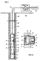
- Fig. 1 illustrates an acoustic logging tool 10 attached at 12 to a wireline cable 24 passing over a sheave 26 to conventional surface wireline equipment (not illustrated).
- transducer pads 30 Disposed about the surface of the tool 10 are a plurality of transducer pads 30 which include transducer elements 40 which function as either transmitters or receivers for an acoustic pulse signal.
- electrical circuitry 20 In electrical communication with transducer element 40 is appropriate electrical circuitry 20 to control operation of the transducers and receive and process information to provide signal amplitudes, travel time and rate of attenuation for determination of bond quality.
- Data is displayed on conventional recorder 22 or other appropriate means.
- the acoustic logging tool 10 is illustrated disposed in a casing 84 cemented with cement 86 to the wall of a borehole 82 in an earth formation 80.
- the transducer pads 30 project from the surface 14 of the tool 10 and may be forced into contact with the casing 84 by spring 46 acting on the rear thereof.
- Upset rings 11 or other centralizers known to those of ordinary skill in the art maintain the tool 10 centrally disposed within the casing 84.
- Transducer pad comprises a transducer element 40 comprising a thin disk shaped member of an appropriate ceramic piezoelectric material, e.g. barium titanate, lead zirconate titanate or the like, centrally disposed within cylindrical support member 32.
- a large backing member 41 comprising a poor acoustical transmission medium such as tungsten loaded epoxy or the like is disposed directly behind the transducer element 40.
- These members are disposed and cushioned in an acoustically absorbent material 42 comprising porous rubber and the like for acoustically isolating the transducer element from the surface 14 of the tool 10.
- the cylindrical support 32 includes a protective member 34 of a protective material such as teflon or the like to protect the transducer element 40 from contact with the interior surface of the casing 84.
- the cylindrical support member 32 ends interiorly with flange 36 having a surface 38 for abutting contact with surface 18 between concentric mounting bores 16 and 17 for limiting the radial travel of the transducer pad 30.
- a spring 46 maintains the transducer pad 30 against the interior surface of the casing 84 or fully extended with flange 36 stopped at surface 18.
- Electrical contacts 44 extend from the transducer element 40 to the control circuits 20 through a central bore 48 through the tool 10.
- Fig. 11 illustrates a transducer pad in accord with the present invention.
- Each transducer pad 30 comprises a pair of transducer elements 40a and 40b operated sequentially as either sequential transmitters or sequential receivers.
- the transducer comprises transducer elements 40a and 40b, centred at a and b, respectively, and preferably disposed along the axis of the tool 10 or the casing 84, both illustrated by line "A".
- the centre-to-centre distance between transducer elements 40a and 40b is d1 .
- the transducer elements 40a and 40b are configured and have centres positioned so that properly timed activation of the elements produces constructive interference of the acoustic pulses along the arc of investigation and destructive interference in other directions.
- transducer elements 40a and 40b When so disposed and activated, transducer elements 40a and 40b produce improved "steered” signals along the arc of investigation.
- the signals When disposed along a line parallel to the tool axis, as illustrated in Fig. 11, the signals may easily be “steered” along the path of both the left and right helices. If disposed along a line not parallel to the tool axis, “steering" along both left and right helices is still possible after the proper delay for each direction is calculated. Although more difficult, calculation of this delay is within the skill of those in the art.
- transducer elements 40a and 40b each include a substantially linear, leading edge disposed perpendicular to the arc of investigation and to a line connecting the transducers/receivers of the array.
- the transducer elements are square with sides one-half the wavelength of the acoustic signal to be transmitted so that the centres a and b and the leading faces are each separated by a distance one-half the acoustic pulse wavelength along this arc.
- sequential activation of transducer elements 40a and 40b in this most preferred embodiment results in maximization of the signal strength at angle 8, also the pitch of the helix and the angle of the arc of investigation in Fig. 11.
- this configuration maximizes the signal strength at ⁇ 45° to produce improved results.
- Fig. 12 illustrates in schematic and block diagram form the major circuits and functions of the present invention. Selection of the transmitters to be activated as each transmitter pair is achieved through transmitter selector means 50 with signal activation controlled by transmitter firing means 52. Selection of the pair of receivers to be activated in conjunction with each activated transmitter is achieved through channel receiver selector 60. The received signal is processed through gain control amplifier 62 to receiver amplitude measurement means 64 and gated timing detector 66. Input and output to and from these circuit control devices is controlled by controller and data acquisition system 68. Finally, signals may be transmitted to and from the controller and data acquisition system 68 over conventional telemetry system 70.
- the above-described control circuitry employs conventional circuits and subcircuits well known to those skilled in the art and, accordingly, need not be further detailed herein.
- an acoustic logging tool useful with the present invention includes five or six transducers symmetrically located in a single plane perpendicular to the axis of the tool 10 and disposed equidistantly about its surface 14 at the vertices of a pentagon or a hexagon, respectively. It could also be said that these transducers are located along the arc of helix of 360° and having a pitch of zero.
- a pentagonal configuration provides five arrays of four equidistantly disposed transducers for providing information concerning each of five sectors comprising 72° about the circumference of the casing. In the hexagonal configuration, six transducer arrays provide similar information concerning each of six equal 60° sectors disposed about the circumference.
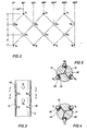
- Fig. 6 relates to one such configuration wherein nine transducers are disposed equidistantly along a single helix of 480° about the longitudinal axis of the tool 10.
- Fig. 6 illustrates the array pattern which would be produced by such a configuration. Where the central pair of any four adjacent transducers functions as receivers and the exterior transducers function as transmitters, the tool which would produce the pattern in Fig. 6 would provide information concerning the bond quality between transducers T2 and T3 with the array comprising transducers T1 -T4.
- transducers T3 and T4 information concerning the bond quality between transducers T3 and T4 would be obtained employing the array comprising transducers T2-T5 and so on until information concerning the bond quality between transducers T7 and T8 is provided by the array comprising transducers T6-T9.
- the RTTR and TTRR configurations illustrated in the summary may be employed in place of the just described TRRT configuration to provide information concerning each sector about the circumference of the casing.
- the transducers need not be spaced apart by 60° and that closer spacing of a greater number of transducers along a helix of greater pitch would permit determination of bond quality in appropriately narrower arcs about the circumference of the casing.
- the distance between adjacent transducers should be maintained preferably at least as great as 3 ⁇ where ⁇ is the wavelength of the acoustic signals in order to produce satisfactory results. Additionally, because the wavelength should not exceed 4t h where t h is the thickness of the casing, the spacing between adjacent transducers should not be less than 12t h . Because t h for conventional casing is one-fourth inch to one-half inch (0.63 cm. to 1.27 cm.), the spacing between adjacent transducers should typically not be less than six inches (15 cm.).
- Fig. 7 illustrates an alternative transducer configuration employing twelve transducers T1-T12 disposed in two helices of 300° each about the surface of a tool 10.
- the transducers are used both as transmitters and receivers.
- the helices are displaced 180° from one another about the surface 14 of the tool 10. Measurements are made similar to those discussed in relation to the single helix having nine transducers.
- the bond quality between T2 and T3, T3 and T4, and T4 and T5 is determined employing the transducers T1 -T6 of the first helix and the bond quality between T8 and T9, T9 and T10, and T10 and T11 is obtained employing the transducers T7-T12 of the second helix.
- two transducers are mounted diametrically in each of six planes perpendicular to the axis of the tool 10 to provide information concerning each of six equidistant segments about the casing in a shorter vertical distance.
- Figs. 2-5 illustrate a configuration of twelve transducers disposed in three helices each of 180° and displaced by 120° about the surface of a tool 10. Such a configuration actually produces four transducers lying on a single arc of each of three left and three right helices such that each helix is employed to determine the bond quality in one of six sectors about a surrounding casing.
- This configuration provides information restricted within a narrow vertical range d.
- each array comprises the two receivers and two transmitters found along each diagonal line of Fig. 2. The measurements are made between adjacent receivers as illustrated by the solid lines of Fig. 2.
- the axes of the two transmitters were at 180° with respect to each other and the measuring arc of the array is the arc between the two receivers R1 and R2.
- T1 transmitted an acoustic pulse signal in the surrounding casing producing a signal first at R1 and later at R2.
- the maximum amplitude of the signal received first at R1 and later at R2 was measured and recorded.
- T2 was then employed to transmit a similar signal which was received and measured first at R2 and then at R1. Further, the time for the signal to travel between R1 and R2 was measured for either one or both of the acoustic compression waves.
- the attenuation rate is determined by the equation: where
- the above device was tested in a simulated borehole wherein the casing was cemented with hydrolite to a simulated borehole wall.
- the casing was 93 ⁇ 4 inches (24.7 cm.) OD conventional casing having a wall thickness of .462 inches (1.17 cm.) or a .22 ⁇ where ⁇ was the wavelength of the acoustic pulse signal.
- a void representative of a 120° unbonded sector was produced about a zero reference point.
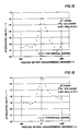
- This model was placed in a water filled tank and measurements were made in an area encompassing the unbonded sector and 60° on either side thereof. Data was obtained at 10° intervals around the pipe periphery and attenuation for the maximum signal E1 and the secondary signal E2 plotted to produce the results illustrated in Figs. 14 and 13, respectively.
- the striking feature of these curves is the symmetric attainment of minimal attenuation at points corresponding to the void or an arc of the pipe having bad bond quality.
- Tool 110 includes twelve adjustably positionable transducer pads 130 disposed in the pad configuration illustrated in Fig. 2.
- Tool 110 includes six adjustable arms, each arm including two transducer pads 130 separated by a spacer bar 128.
- Each arm further includes an upper arm 124 hingedly affixed to the central body portion 120 of the tool 110 at its upper end and hingedly affixed at 134 to the upper transducer pad 130a.
- a similar lower arm 126 is hingedly affixed at its lower end to the central tool portion 120 and hingedly affixed at its upper end to the bottom of lower pad 130b.
- arms 124 and 126 are slidable along central portion 120 of the tool 110 to permit a slidable ring and motor (not shown) to push and pull the arms along the central portion 120 of the tool 110 to extend or retract, respectively, the transducer pads 130.
- the pads 130 are pulled flush against the central tool portion 120 within insets 122 to provide a tool more easily pulled through the casing.
- Extension of the arms carrying transducer pads 130 places the transducer elements 140a and 140b mounted within an absorbent material 142 to be brought into near contact with the inner wall of the casing to be tested.
- Apparatus and methods according to the invention are also useful for making azimuthally dependent measurements in hard formations to detect fractures in uncased boreholes. When detecting fractures, the attenuation of the acoustic shear wave rather than the compression wave is measured.
Description
- The present invention relates to an apparatus and method for acoustic logging and more specifically to an apparatus and method useful for determining the quality of the cement bond between a wall of a borehole penetrating an earth formation and a casing cemented therein.
- In the oil and gas industry, wells are completed by setting a string of pipe or casing in the borehole and filling the annulus between the pipe or casing and the borehole with cement. This cementing operation separates the various formation zones, and particularly separates the productive oil and gas bearing formations from non-productive formations such as water-bearing formations. Once separated by the cementing operation, only the desired oil and gas bearing formations are perforated for production. Failure or incompleteness of the cement bonds will likely result in incomplete separation between the various formations. Migration of fluids under pressure through voids or cracks appearing in the cement between the casing and borehole wall cause contamination of the fluids of one zone with the fluids of another zone. This contamination is particularly undesirable where fluids from water-bearing strata migrate into fluids in a producing zone. This migration typically results in decreased production of hydrocarbon fluids and increased production of non-desirable fluids and contamination of equipment. These results often cause serious financial loss and may even cause a well to become non-commercial.
- Accordingly, the desirability of accurately determining the quality of the cement bond between a casing and a wall of a borehole has long been a goal of those associated with the oil and gas industry. A "good bond" produces the desired separation of zones and is achieved with good adhesion, although micro-fissures or a micro-annulus may be present.
- Many prior systems have been developed for investigating the bond quality between a casing and a borehole wall. Prior systems for inspecting the cement bond in wells in the oil and gas industry have included conventional acoustic cement bond systems employing acoustic energy in a variety of devices and methods. Such a system is described in US-A-4255798 which employs an acoustic pulse echo technique for investigating the quality of the cement bond to a casing and the thickness of a casing located in a borehole. It lists and describes in columns 2-7 a plurality of patents and articles describing in detail many prior art systems for evaluating cement bond quality using acoustic energy. Document US-A-3781784, discloses an arrangement of two transmitters emitting at different frequencies and two receivers, the attenuation of signals travelling between the transmitters and receivers being used to estimate the characteristics of a geological formation adjacent to the arrangement. US-A-3811529 discloses a similar arrangement, but with four receivers spaced at 90° intervals around a circumference of a wellbore tool, and a single transmitter located beneath the receivers and centred in the wellbore. In addition, US-A-4255798 describes a plurality of transducers arranged circumferentially around a wellbore tool, the transducers being vertically displaced, each acting to determine cement bond quality behind the casing. Each transducer makes its own determination, so there is no measurement over an arc.
- However, these prior acoustic systems typically suffer from one or two major drawbacks. Many of these prior systems merely provide an average indication of the bond quality about the entire circumference of the casing at the measured depth within the borehole. Accordingly, the investigator using such systems cannot determine the specific azimuthal location about the borehole where a channel may be located. In fact, the investigator cannot distinguish a troublesome channel from several small fissures. Other systems which do provide azimuthal scanning measure the bond condition at only specific points around the circumference and give no indication of the bond condition over the arc between those points.
- According to one aspect of the present invention, there is provided an acoustic logging apparatus comprising a sonde for positioning within a borehole and comprising a plurality of transducers, two of said transducers being operable for transmitting acoustic pulse signals and two of said transducers being operable for receiving acoustic pulse signals, there being means for operating the two transmitting transducers and means for generating a signal responsive to the amplitudes of acoustic pulse signals received by the two receiving transducers and resulting from transmissions from the two transmitting transducers and representative of an acoustic transmission characteristic of a path lying along an exterior surface of the sonde, characterised in that each transducer is operable as a receiver and a transmitter, selectively, the transducers being arranged in such number and disposition that the operating means is able to operate said transducers as a plurality of arrays in different planes, each of a plurality of the transducers being capable of belonging to more than one array and each array including four of said transducers disposed on an arc extending along said exterior surface with two of said transducers in each array being operated as transmitters and two as receivers.
- The transducers of each array may be disposed so that the transducers of an adjacent pair of transducers in each array perform the same function in the array. The preferred transducer pattern in the arrays is T₁-R₁-R₂-T₂. Other acceptable transducer patterns in the arrays include R₁-T₁-T₂-R₂ and T₁-T₂-R₁-R₂. These arrays permit a determination of the bond quality between the adjacent transducers performing the same function in the array. The arrays are preferably disposed along the pitch of one or more helices along the axis of the tool.
- In one example transducers are configured for transmitting maximum strength acoustic signals and receiving minimum strength acoustic signals to improve the detection limits for a bond quality apparatus.
- The transducer configuration in an embodiment of the invention provides a means for maximizing the signal transmitted or received along the arc of investigation about the surrounding casing or borehole. Each transducer comprises at least two sequentially operated transducer elements. In a preferred embodiment, each transducer comprises a pair of square transducer elements placed along the axis of the tool or borehole, having dimensions one-half the acoustic wave length and disposed so that the edges of the square are perpendicular to the line of the transmission along the pitch of a helix and preferably at 45° angles to the tool axis. The individual elements of these transducers are sequentially operated in order to maximize the signal strength transmitted along the pitch of the helix, preferably at ± 45° to the tool or casing axis and directed toward the receiving transducers. Use of transducer elements of this configuration maximises the signal strength along the arc of investigation and improves the accuracy of bond quality determination.
- The logging apparatus may further comprise means for generating a first acoustic and a second acoustic pulse signal from the second transmitting transducer and means for measuring the maximum amplitude of a portion of the first signal received at each of the first and second receiving transducers. Finally, the apparatus may comprise means for determining the time for either of the acoustic pulse signals to travel between the adjacent pair of similarly functioning transducers which define the first and second circumferentially separated points between which the bond quality is determined.
- In electrical communication with the above measuring and determining means is means for computing the rate of attenuation of the acoustic pulse signals between the adjacent pair of similarly functioning transducers based on the measured maximum amplitudes and travel time. In more preferred embodiments, the transducers are equidistantly spaced about an elongated housing having a longitudinal axis. In an exemplary configuration, five transducers equidistantially spaced about the housing in a single plane perpendicular to the longitudinal axis of the housing produce five different transducer arrays providing measurements of bond quality behind each of five segments of 72° each. Because of geometry problems encountered in disposing the transducers about the housing, particularly where smaller measurement arcs are desired, more preferred embodiments provide the helical disposition of the transducers. In a presently preferred embodiment, nine transducers are disposed equidistantly along a single helix of 480° providing measurement about six segments each of 60°. Alternative preferred embodiments include twelve transducers disposed in two helices of six transducers each, the two helices being displaced 180° about the housing. Another alternative embodiment comprises twelve transducers disposed in three helices of four transducers each, each helix being displaced 120° about the housing. Adjacent transducers are preferably separated by a distance at least as great as 3λ where λ is the wavelength of the acoustic pulse signals of the system or by a distance at least as great as 12th where th is the thickness of the casing of the borehole.
- The apparatus may still further include means for displaying the rate of attenuation and for comparing the computed attenuation with an attenuation indicative of a good bond.
- According to another aspect of the invention, there is provided an acoustic logging method which includes positioning a sonde within a borehole, the sonde comprising a plurality of transducers, two of said transducers being operable for transmitting acoustic pulse signals and two of said transducers being operable for receiving acoustic pulse signals, operating the two transmitting transducers and generating a signal responsive to the amplitudes of acoustic pulse signals received by the two receiving transducers and resulting from transmissions from the two transmitting transducers and representative of an acoustic transmission characteristic of a path lying along an exterior surface of the sands, characterised by operating each transducer as a receiver and transmitter, selectively, and operating said transducers as a plurality of arrays in different planes, each of a plurality of the transducers being capable of belonging to more than one array and each array including four of said transducers disposed on an arc extending along said exterior surface, and defining such a path lying in a sector of the circumference of the said borehole, with two of said transducers in each array operating as transmitters and two as receivers.
- The method may comprise the steps of transmitting a first acoustic compression wave through the casing along an arc defined by first and second circumferentially separated points so that the wave arrives at the first point before arriving at the second point. The strength of the transmitted and received signal is enhanced by sequentially activating a pair of transducer elements comprising each transducer. The transducer elements each include a straight, leading face perpendicular to the arc of investigation on a line toward the receiver. Sequential activation of these elements with appropriate time delay maximises the transmitted and received signal strength. The maximum amplitude of the wave is measured at both the first and second points together with the time for the wave to travel between the first and second points. The method may further comprise transmitting a second acoustic compression wave through the casing and along the arc and measuring the maximum amplitude of the second wave received at each of the first and second points. The method may further comprise computing the rate of attenuation for the acoustic compression wave between the first and second points from the four measured amplitudes and the measured travel time and displaying the rate of attenuation as an indication of the quality of the cement bond. Alternatively, or additionally, the computed attenuation is compared to the attenuation for a good bond or bond of known quality. If the depth and orientation within the borehole is not previously known, the method may further comprise measuring the azimuth of the borehole and the depth within the borehole.
- Embodiments of the apparatus and method of the present invention can provide means for accurately determining the quality of the cement bond behind an arc of the casing in a cemented borehole, and/or for precisely locating channels, fissures and other imperfections in the cement behind the casing.
- For a better understanding of the invention, and to show how the same may be carried into effect, reference will now be made, by way of example, to the accompanying drawings, in which:
- Fig. 1 is an illustration of a wireline acoustic logging tool within a cemented casing in a borehole.
- Fig. 1A is a cross-sectional illustration of an acoustic transducer useful in the acoustic logging tool;
- Fig. 2 is an illustration of a projection of a transducer pattern of a triple helix, each helix of 180° displaced 120° about an acoustic logging tool;
- Fig. 3 is an illustration of a portion of the exterior of an acoustic logging tool which would produce the transducer array pattern of Fig. 2;
- Fig. 4 is a cross-sectional illustration of the acoustic logging tool of Fig. 3 on the line 4-4;
- Fig. 5 is a cross-sectional illustration of the acoustic logging tool of Fig. 3 on the line 5-5;
- Fig. 6 is an illustration of a projection of a transducer pattern of a single helix of 480° about an acoustic logging tool;
- Fig. 7 is an illustration of a projection of a transducer pattern of two helices, each helix of 300° and displaced 180° about an acoustic logging tool;
- Fig. 8 is a side illustration of a presently preferred embodiment of the invention;
- Fig. 9 is a cross-sectional of Fig. 8 on the line 9-9;
- Fig. 10 is an illustration of an acoustic transducer pad of Fig. 8;
- Fig. 11 is an illustration of a portion of an acoustic logging tool having a directional transducer;
- Fig. 12 is a block diagram of the major components and circuits of an acoustic logging tool;
- Fig. 13 is a graphical illustration of the attenuation observed in a test casing having a cement void in an arch approximately 120° wide and centred at the designated position zero;
- Fig. 14 is a graphical illustration of the attenuation observed in a test casing having a cement void in an arc approximately 120° wide and centred at the designated position zero;
- Fig. 15 is a graphical illustration of the attenuation observed in a test casing having a cement void in an arc approximately 17.6° wide and centred at the designated position zero;
- Fig. 16 is a graphical illustration of the attenuation observed in a test casing having a cement void in an arc approximately 17.6° wide and centred at the designated position zero; and
- Fig. 17 is a graphical illustration of an output signal for an acoustic logging tool producing results for six sectors forming a circumference about the casing and illustrating various bond characteristics.
- The present invention is directed to an apparatus and method useful for determining the quality of a bond between a wall of a borehole penetrating an earth formation and a casing cemented therein. This determination is made between two circumferentially separated points on an arc of the casing. The apparatus and method of the present invention employs a plurality of transducers for transmitting and receiving an acoustic pulse compression wave through the casing between the two circumferentially separated points. Measurement of the maximum amplitude of a selected portion of the signal received by transducers located at the two separated points and the travel time therebetween for each of two such acoustic pulse compression waves permits calculation of the rate of attenuation of the acoustic pulse signal between the two points and comparison with the attenuation between similar points for a good bond or a bond of known quality.
- Fig. 1 illustrates an
acoustic logging tool 10 attached at 12 to awireline cable 24 passing over asheave 26 to conventional surface wireline equipment (not illustrated). Disposed about the surface of thetool 10 are a plurality oftransducer pads 30 which includetransducer elements 40 which function as either transmitters or receivers for an acoustic pulse signal. In electrical communication withtransducer element 40 is appropriateelectrical circuitry 20 to control operation of the transducers and receive and process information to provide signal amplitudes, travel time and rate of attenuation for determination of bond quality. Data is displayed onconventional recorder 22 or other appropriate means. - The
acoustic logging tool 10 is illustrated disposed in acasing 84 cemented withcement 86 to the wall of a borehole 82 in anearth formation 80. Thetransducer pads 30 project from thesurface 14 of thetool 10 and may be forced into contact with thecasing 84 byspring 46 acting on the rear thereof. Upset rings 11 or other centralizers known to those of ordinary skill in the art maintain thetool 10 centrally disposed within thecasing 84. - Fig. 1A illustrates in greater detail an
exemplary transducer pad 30 for use in atool 10. Transducer pad comprises atransducer element 40 comprising a thin disk shaped member of an appropriate ceramic piezoelectric material, e.g. barium titanate, lead zirconate titanate or the like, centrally disposed withincylindrical support member 32. Alarge backing member 41 comprising a poor acoustical transmission medium such as tungsten loaded epoxy or the like is disposed directly behind thetransducer element 40. These members are disposed and cushioned in an acousticallyabsorbent material 42 comprising porous rubber and the like for acoustically isolating the transducer element from thesurface 14 of thetool 10. Thecylindrical support 32 includes aprotective member 34 of a protective material such as teflon or the like to protect thetransducer element 40 from contact with the interior surface of thecasing 84. Thecylindrical support member 32 ends interiorly withflange 36 having asurface 38 for abutting contact withsurface 18 between concentric mounting bores 16 and 17 for limiting the radial travel of thetransducer pad 30. Aspring 46 maintains thetransducer pad 30 against the interior surface of thecasing 84 or fully extended withflange 36 stopped atsurface 18. A similar acoustic transceiver pad is described in US-A-3811529 at Fig. 4 which is incorporated herein by reference.Electrical contacts 44 extend from thetransducer element 40 to thecontrol circuits 20 through acentral bore 48 through thetool 10. - Fig. 11 illustrates a transducer pad in accord with the present invention. Each
transducer pad 30 comprises a pair oftransducer elements 40a and 40b operated sequentially as either sequential transmitters or sequential receivers. The transducer comprisestransducer elements 40a and 40b, centred at a and b, respectively, and preferably disposed along the axis of thetool 10 or thecasing 84, both illustrated by line "A". The centre-to-centre distance betweentransducer elements 40a and 40b is d₁ . Thetransducer elements 40a and 40b are configured and have centres positioned so that properly timed activation of the elements produces constructive interference of the acoustic pulses along the arc of investigation and destructive interference in other directions. When so disposed and activated,transducer elements 40a and 40b produce improved "steered" signals along the arc of investigation. When disposed along a line parallel to the tool axis, as illustrated in Fig. 11, the signals may easily be "steered" along the path of both the left and right helices. If disposed along a line not parallel to the tool axis, "steering" along both left and right helices is still possible after the proper delay for each direction is calculated. Although more difficult, calculation of this delay is within the skill of those in the art. - In the preferred embodiment,
transducer elements 40a and 40b each include a substantially linear, leading edge disposed perpendicular to the arc of investigation and to a line connecting the transducers/receivers of the array. In the most preferred embodiment, the transducer elements are square with sides one-half the wavelength of the acoustic signal to be transmitted so that the centres a and b and the leading faces are each separated by a distance one-half the acoustic pulse wavelength along this arc. Properly timed, sequential activation oftransducer elements 40a and 40b in this most preferred embodiment results in maximization of the signal strength atangle 8, also the pitch of the helix and the angle of the arc of investigation in Fig. 11. In this most preferred embodiment, where the pitch of the helix of the transducer configuration is 45° and the angle between the tool axis and the line connecting the centres a and b of thetransducer elements 40a and 40b is zero, this configuration maximizes the signal strength at ± 45° to produce improved results. The firing of the transducer element closest to the receivers, in the illustration transducer element 40a forreceivers 34 ortransducer element 40b for receivers (not illustrated) located abovetransducer pad 30, is delayed by a time factor td = d₂/Vs where d₂ is the distance along the arc of investigation between perpendiculars dropped from the centres a and b of the transducer elements. Specifically,
where - td =
- the time delay between the firing of
transducer elements 40a and 40b; - d₁ =
- the centre-to-centre distance between
transducer elements 40a and 40b; - Vs =
- the speed of the acoustic wave in the arc of determination in the casing or formation; and
- ϑ =
- the angle between the line connecting the centres a and b of the
transducer elements 40a and 40b and the arc of investigation. - Fig. 12 illustrates in schematic and block diagram form the major circuits and functions of the present invention. Selection of the transmitters to be activated as each transmitter pair is achieved through transmitter selector means 50 with signal activation controlled by transmitter firing means 52. Selection of the pair of receivers to be activated in conjunction with each activated transmitter is achieved through
channel receiver selector 60. The received signal is processed throughgain control amplifier 62 to receiver amplitude measurement means 64 andgated timing detector 66. Input and output to and from these circuit control devices is controlled by controller and data acquisition system 68. Finally, signals may be transmitted to and from the controller and data acquisition system 68 overconventional telemetry system 70. The above-described control circuitry employs conventional circuits and subcircuits well known to those skilled in the art and, accordingly, need not be further detailed herein. - In two of its embodiments, an acoustic logging tool useful with the present invention includes five or six transducers symmetrically located in a single plane perpendicular to the axis of the
tool 10 and disposed equidistantly about itssurface 14 at the vertices of a pentagon or a hexagon, respectively. It could also be said that these transducers are located along the arc of helix of 360° and having a pitch of zero. A pentagonal configuration provides five arrays of four equidistantly disposed transducers for providing information concerning each of five sectors comprising 72° about the circumference of the casing. In the hexagonal configuration, six transducer arrays provide similar information concerning each of six equal 60° sectors disposed about the circumference. However, in reality, such planar distribution of transducers is difficult to achieve because of the crowding resulting from attempting to place five or six transducers in a single plane in a tool whose diameter is restricted for passage through a borehole. Accordingly, there are several preferred embodiments for disposition of a minimal plurality of transducers to produce the desired results. - Fig. 6 relates to one such configuration wherein nine transducers are disposed equidistantly along a single helix of 480° about the longitudinal axis of the
tool 10. Fig. 6 illustrates the array pattern which would be produced by such a configuration. Where the central pair of any four adjacent transducers functions as receivers and the exterior transducers function as transmitters, the tool which would produce the pattern in Fig. 6 would provide information concerning the bond quality between transducers T₂ and T₃ with the array comprising transducers T₁ -T₄. Similarly, information concerning the bond quality between transducers T₃ and T₄ would be obtained employing the array comprising transducers T₂-T₅ and so on until information concerning the bond quality between transducers T₇ and T₈ is provided by the array comprising transducers T₆-T₉. Those skilled in the art will readily comprehend that other configurations, e.g. the RTTR and TTRR configurations illustrated in the summary may be employed in place of the just described TRRT configuration to provide information concerning each sector about the circumference of the casing. Further, those skilled in the art will appreciate the transducers need not be spaced apart by 60° and that closer spacing of a greater number of transducers along a helix of greater pitch would permit determination of bond quality in appropriately narrower arcs about the circumference of the casing. However, it should be noted that the distance between adjacent transducers should be maintained preferably at least as great as 3λ where λ is the wavelength of the acoustic signals in order to produce satisfactory results. Additionally, because the wavelength should not exceed 4th where th is the thickness of the casing, the spacing between adjacent transducers should not be less than 12th. Because th for conventional casing is one-fourth inch to one-half inch (0.63 cm. to 1.27 cm.), the spacing between adjacent transducers should typically not be less than six inches (15 cm.). - Fig. 7 illustrates an alternative transducer configuration employing twelve transducers T₁-T₁₂ disposed in two helices of 300° each about the surface of a
tool 10. The transducers are used both as transmitters and receivers. The helices are displaced 180° from one another about thesurface 14 of thetool 10. Measurements are made similar to those discussed in relation to the single helix having nine transducers. In this configuration, the bond quality between T₂ and T₃, T₃ and T₄, and T₄ and T₅ is determined employing the transducers T₁ -T₆ of the first helix and the bond quality between T₈ and T₉, T₉ and T₁₀, and T₁₀ and T₁₁ is obtained employing the transducers T₇-T₁₂ of the second helix. In this configuration, two transducers are mounted diametrically in each of six planes perpendicular to the axis of thetool 10 to provide information concerning each of six equidistant segments about the casing in a shorter vertical distance. - Figs. 2-5 illustrate a configuration of twelve transducers disposed in three helices each of 180° and displaced by 120° about the surface of a
tool 10. Such a configuration actually produces four transducers lying on a single arc of each of three left and three right helices such that each helix is employed to determine the bond quality in one of six sectors about a surrounding casing. This configuration provides information restricted within a narrow vertical range d. In this configuration, each array comprises the two receivers and two transmitters found along each diagonal line of Fig. 2. The measurements are made between adjacent receivers as illustrated by the solid lines of Fig. 2. - A test device having transmitters T₁ and T₂ and receivers R₁ and R₂, in the pattern TRRT, was constructed wherein the transducers were configured about a 180° helix, each separated by 60° and with a vertical distance d of 6 inches (15 cm.) in accord with the configuration shown in Figs. 2 and 3 as, for example, T₁ R₂ R₃ T₄ or T₃R₄R₅T₆. The axes of the two transmitters were at 180° with respect to each other and the measuring arc of the array is the arc between the two receivers R₁ and R₂.
- In use, T₁ transmitted an acoustic pulse signal in the surrounding casing producing a signal first at R₁ and later at R₂. The maximum amplitude of the signal received first at R₁ and later at R₂ was measured and recorded. T₂ was then employed to transmit a similar signal which was received and measured first at R₂ and then at R₁. Further, the time for the signal to travel between R₁ and R₂ was measured for either one or both of the acoustic compression waves. The attenuation rate is determined by the equation:

where - α₁₂ =
- the attenuation rate between R₁ and R₂;
- Vs =
- the speed of the acoustic wave in the casing;
- Aij =
- the amplitude of the signal received at Rj from transmitter Ti where i = 1 or 2 and j = 1 or 2; and
- tij =
- the time at which the signal from Ti is received at Rj where i = 1 or 2 and j = 1 or 2.
- The above device was tested in a simulated borehole wherein the casing was cemented with hydrolite to a simulated borehole wall. The casing was 9¾ inches (24.7 cm.) OD conventional casing having a wall thickness of .462 inches (1.17 cm.) or a .22λ where λ was the wavelength of the acoustic pulse signal. A void representative of a 120° unbonded sector was produced about a zero reference point. This model was placed in a water filled tank and measurements were made in an area encompassing the unbonded sector and 60° on either side thereof. Data was obtained at 10° intervals around the pipe periphery and attenuation for the maximum signal E¹ and the secondary signal E² plotted to produce the results illustrated in Figs. 14 and 13, respectively. The striking feature of these curves is the symmetric attainment of minimal attenuation at points corresponding to the void or an arc of the pipe having bad bond quality.
- A similar test was undertaken with a test annulus having a void representative of a 17.6° vertical channel at reference point zero. All other conditions were identical. The results of the measured attenuation are illustrated in Figs. 15 and 16 showing a significant measurable attenuation difference most pronounced at the narrow vertical channel.
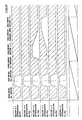
- The incorporation of such a device in a wireline acoustic logging tool employing a conventional strip chart recorder could result in easily readable output such as that illustrated in Fig. 17. Conventional depth and
azimuth devices 13 would provide the operator with the depth of each measurement and the azimuthal location of each of sectors 1-2, 2-3 through 6-1. Such a device can easily indicate whether the casing and cement have formed a good bond about the entire periphery of the casing or whether a bad bond exists in one or more of the measured sectors thereabout. - The tool illustrated in Figs. 8-10 is the presently preferred embodiment of a wireline tool in accord with the present invention.
Tool 110 includes twelve adjustablypositionable transducer pads 130 disposed in the pad configuration illustrated in Fig. 2.Tool 110 includes six adjustable arms, each arm including twotransducer pads 130 separated by aspacer bar 128. Each arm further includes anupper arm 124 hingedly affixed to thecentral body portion 120 of thetool 110 at its upper end and hingedly affixed at 134 to theupper transducer pad 130a. A similarlower arm 126 is hingedly affixed at its lower end to thecentral tool portion 120 and hingedly affixed at its upper end to the bottom oflower pad 130b. Either one or both ofarms central portion 120 of thetool 110 to permit a slidable ring and motor (not shown) to push and pull the arms along thecentral portion 120 of thetool 110 to extend or retract, respectively, thetransducer pads 130. In the retracted position, thepads 130 are pulled flush against thecentral tool portion 120 withininsets 122 to provide a tool more easily pulled through the casing. Extension of the arms carryingtransducer pads 130 places thetransducer elements absorbent material 142 to be brought into near contact with the inner wall of the casing to be tested. - There has been illustrated and described a device and method employing a plurality of transducers each having two transducer elements equidistantly spaced along one or more helices. However, those skilled in the art will be aware that a plurality of transducer elements spaced and properly sequentially activated may be employed to further improve the directional signal strength.
- Apparatus and methods according to the invention are also useful for making azimuthally dependent measurements in hard formations to detect fractures in uncased boreholes. When detecting fractures, the attenuation of the acoustic shear wave rather than the compression wave is measured.
Claims (16)
- An acoustic logging apparatus comprising a sonde (10) for positioning within a borehole (82) and comprising a plurality of transducers (40), two of said transducers (40) being operable for transmitting acoustic pulse signals and two of said transducers (40) being operable for receiving acoustic pulse signals, there being means (20, 50, 60) for operating the two transmitting transducers and means (20, 64, 70) for generating a signal responsive to the amplitudes of acoustic pulse signals received by the two receiving transducers and resulting from transmissions from the two transmitting transducers and representative of an acoustic transmission characteristic of a path lying along an exterior surface of the sonde, characterised in that each transducer (40) is operable as a receiver and a transmitter, selectively, the transducers being arranged in such number and disposition that the operating means (20, 50, 60) is able to operate said transducers as a plurality of arrays in different planes, each of a plurality of the transducers being capable of belonging to more than one array and each array including four of said transducers disposed on an arc extending along said exterior surface with two of said transducers in each array being operated as transmitters (T) and two as receivers (R).
- An apparatus according to claim 1 wherein said signal generating means (20, 64, 70) includes means for determining the travel time of an acoustic pulse signal travelling between the two receiving transducers (R) in respect of each said operated array of transducers (40).
- An apparatus according to claim 1 or 2 wherein said signal generating means (20, 64, 70) includes means for determining the attenuation of an acoustic pulse signal travelling between the two receiving transducers (R) in respect of each said operated array of transducers (40).
- An apparatus according to any one of the preceding claims including a plurality of pads (30) adapted to be extended radially from said sonde (10) to contact a wall or casing of a borehole when the sonde is received therein, said transducers (40) being disposed adjacent to the exterior surfaces of said pads.
- An apparatus according to any one of the preceding claims wherein adjacent transducers (40) are spaced apart by a distance at least as great as three times the selected wavelength of the acoustic pulse signal.
- An apparatus according to any of the preceding claims wherein each said transducer (40) comprises first and second transducer elements (40a, 40b), and said operating means (20, 50, 60) activates said first and second elements in a sequence selected to tend to enhance the amplitude of the acoustic pulse signal in a direction along said arc.
- An apparatus according to any one of the preceding claims wherein said transducers (40) are disposed in at least one helix about a longitudinal axis of said sonde (10).
- An apparatus according to claim 7 including twelve said transducers (40) disposed in two said helices of six transducers each, said transducers being disposed in six planes perpendicular to said longitudinal axis, and each said plane including one transducer pertaining to one of said helices disposed diametrically opposite one transducer pertaining to the other of said helices.
- An apparatus according to claim 7 including twelve of said transducers (4) disposed in three said helices of four transducers each, said transducers being disposed in four planes perpendicular to said longitudinal axis, and each said plane including one transducer pertaining to each said helix disposed at 120° from each other about said axis.
- An apparatus according to claim 7 including nine said transducers (40) disposed in one said helix of 480° about said axis, said operating means (20, 50, 60) operating said transducers in six arrays with four of said transducers in each said array.
- An apparatus according to any one of the preceding claims wherein said apparatus is adapted for reception in a casing cemented within said borehole, and said signals provided by said signal generating means (20, 64, 70) are representative of the quality of the cement bond between the casing and the borehole wall in the respective sectors about said axis associated with each said operated array of transducers.
- An acoustic logging method which includes positioning a sonde (10) within a borehole (82), the sonde comprising a plurality of transducers, two of said transducers (40) being operable for transmitting acoustic pulse signals and two of said transducers (40) being operable for receiving acoustic pulse signals, operating the two transmitting transducers and generating a signal responsive to the amplitudes of acoustic pulse signals received by the two receiving transducers and resulting from transmissions from the two transmitting transducers and representative of an acoustic transmission characteristic of a path lying along an exterior surface of the sonde, characterised by operating each transducer as a receiver and transmitter, selectively, and operating said transducers as a plurality of arrays in different planes, each of a plurality of the transducers being capable of belonging to more than one array and each array including four of said transducers disposed on an arc extending along said exterior surface, and defining such a path lying in a sector of the circumference of the said borehole, with two of said transducers in each array operating as transmitters (T) and two as receivers (R).
- A method according to claim 12 wherein said step of generating a signal includes determining the attenuation of the acoustic pulse signal travelling between the two receiving transducers.
- A method according to claim 12 or 13 including repeating the steps of claim 12 in respect of different such sectors to complete a circumference about said sonde.
- A method according to any one of claims 12 to 14 carried out in a borehole having a casing cemented therein, wherein said step of generating a signal comprises generating a signal representative of the quality of the cement bond between the casing and the borehole wall in the respective sector.
- A method according to claim 15 including comparing said cement bond quality signal with a similar signal representative of a cement bond of predetermined quality.
Applications Claiming Priority (2)
| Application Number | Priority Date | Filing Date | Title |
|---|---|---|---|
| US910076 | 1986-09-22 | ||
| US06/910,076 US4805156A (en) | 1986-09-22 | 1986-09-22 | System for acoustically determining the quality of the cement bond in a cased borehole |
Publications (3)
| Publication Number | Publication Date |
|---|---|
| EP0261825A2 EP0261825A2 (en) | 1988-03-30 |
| EP0261825A3 EP0261825A3 (en) | 1989-08-23 |
| EP0261825B1 true EP0261825B1 (en) | 1992-06-03 |
Family
ID=25428278
Family Applications (1)
| Application Number | Title | Priority Date | Filing Date |
|---|---|---|---|
| EP87307820A Expired - Lifetime EP0261825B1 (en) | 1986-09-22 | 1987-09-04 | Method and apparatus for acoustic logging of boreholes |
Country Status (6)
| Country | Link |
|---|---|
| US (1) | US4805156A (en) |
| EP (1) | EP0261825B1 (en) |
| CA (1) | CA1283201C (en) |
| DE (1) | DE3779538T2 (en) |
| DK (1) | DK166396C (en) |
| NO (1) | NO171468C (en) |
Families Citing this family (57)
| Publication number | Priority date | Publication date | Assignee | Title |
|---|---|---|---|---|
| US4896303A (en) * | 1986-09-30 | 1990-01-23 | Schlumberger Technology Corporation | Method for cementation evaluation using acoustical coupling and attenuation |
| NO172359C (en) * | 1986-09-30 | 1993-07-07 | Schlumberger Ltd | PROCEDURE AND APPARATUS FOR DETERMINING PROPERTIES OF MATERIAL BACK LINING ROOMS |
| US5146050A (en) * | 1989-04-25 | 1992-09-08 | Western Atlas International, Inc. | Method and apparatus for acoustic formation dip logging |
| US5130950A (en) * | 1990-05-16 | 1992-07-14 | Schlumberger Technology Corporation | Ultrasonic measurement apparatus |
| DE4117638A1 (en) * | 1990-05-30 | 1991-12-05 | Toshiba Kawasaki Kk | SHOCK WAVE GENERATOR WITH A PIEZOELECTRIC ELEMENT |
| US6018496A (en) * | 1991-12-17 | 2000-01-25 | Schlumberger Technology Corporation | Method and apparatus for hydraulic isolation determination |
| CA2133286C (en) * | 1993-09-30 | 2005-08-09 | Gordon Moake | Apparatus and method for measuring a borehole |
| US5763773A (en) * | 1996-09-20 | 1998-06-09 | Halliburton Energy Services, Inc. | Rotating multi-parameter bond tool |
| US5924499A (en) * | 1997-04-21 | 1999-07-20 | Halliburton Energy Services, Inc. | Acoustic data link and formation property sensor for downhole MWD system |
| US6002639A (en) * | 1997-05-14 | 1999-12-14 | Gas Research Institute | Sensor configuration for nulling reverberations to image behind reflective layers |
| US6125079A (en) * | 1997-05-14 | 2000-09-26 | Gas Research Institute | System and method for providing dual distance transducers to image behind an acoustically reflective layer |
| US6021093A (en) * | 1997-05-14 | 2000-02-01 | Gas Research Institute | Transducer configuration having a multiple viewing position feature |
| US5995447A (en) * | 1997-05-14 | 1999-11-30 | Gas Research Institute | System and method for processing acoustic signals to image behind reflective layers |
| US5841734A (en) * | 1997-06-05 | 1998-11-24 | Halliburton Energy Services, Inc. | Rotating acoustic transducer head for cement bond evaluation tool |
| US6098017A (en) * | 1997-09-09 | 2000-08-01 | Halliburton Energy Services, Inc. | Adjustable head assembly for ultrasonic logging tools that utilize a rotating sensor subassembly |
| US6085836A (en) * | 1997-10-15 | 2000-07-11 | Burris; Sanford A. | Well pump control using multiple sonic level detectors |
| US6213250B1 (en) * | 1998-09-25 | 2001-04-10 | Dresser Industries, Inc. | Transducer for acoustic logging |
| US6354146B1 (en) | 1999-06-17 | 2002-03-12 | Halliburton Energy Services, Inc. | Acoustic transducer system for monitoring well production |
| US6310426B1 (en) * | 1999-07-14 | 2001-10-30 | Halliburton Energy Services, Inc. | High resolution focused ultrasonic transducer, for LWD method of making and using same |
| US6568271B2 (en) | 2001-05-08 | 2003-05-27 | Halliburton Energy Services, Inc. | Guided acoustic wave sensor for pipeline build-up monitoring and characterization |
| US20040136267A1 (en) * | 2003-01-10 | 2004-07-15 | Kear George R. | Dual imaging sonde including a rotationally and vertically offset second imaging tool |
| US20060203612A1 (en) * | 2003-01-10 | 2006-09-14 | Schlumberger Technology Corporation | Sonde System Including Rotationally and Vertically Offset Tools |
| EP1464959B1 (en) * | 2003-04-03 | 2006-07-12 | Services Petroliers Schlumberger | Acoustic method for cement bond evaluation in boreholes |
| US20050128873A1 (en) * | 2003-12-16 | 2005-06-16 | Labry Kenneth J. | Acoustic device and method for determining interface integrity |
| US7525872B2 (en) * | 2004-02-26 | 2009-04-28 | Baker Hughes Incorporated | Method and apparatus for cement bond evaluation using transversely polarized shear waves |
| US7663969B2 (en) * | 2005-03-02 | 2010-02-16 | Baker Hughes Incorporated | Use of Lamb waves in cement bond logging |
| US7150317B2 (en) * | 2004-03-17 | 2006-12-19 | Baker Hughes Incorporated | Use of electromagnetic acoustic transducers in downhole cement evaluation |
| US7697375B2 (en) * | 2004-03-17 | 2010-04-13 | Baker Hughes Incorporated | Combined electro-magnetic acoustic transducer |
| EP1672169B1 (en) * | 2004-12-20 | 2009-07-22 | Services Petroliers Schlumberger | Method to measure and locate a fluid communication pathway in a material behind a casing |
| US8256565B2 (en) * | 2005-05-10 | 2012-09-04 | Schlumberger Technology Corporation | Enclosures for containing transducers and electronics on a downhole tool |
| US7913806B2 (en) * | 2005-05-10 | 2011-03-29 | Schlumberger Technology Corporation | Enclosures for containing transducers and electronics on a downhole tool |
| US20070070811A1 (en) * | 2005-08-23 | 2007-03-29 | Baker Hughes, Inc. | Multiple tracks scanning tool |
| US7787327B2 (en) * | 2006-11-15 | 2010-08-31 | Baker Hughes Incorporated | Cement bond analysis |
| WO2009038456A1 (en) * | 2007-09-18 | 2009-03-26 | Röntgen Technische Dienst B.V. | Inspection device and method for inspection |
| US20090231954A1 (en) * | 2008-03-17 | 2009-09-17 | Baker Hughes Incorporated | Micro-Annulus Detection Using Lamb Waves |
| US9175559B2 (en) * | 2008-10-03 | 2015-11-03 | Schlumberger Technology Corporation | Identification of casing collars while drilling and post drilling using LWD and wireline measurements |
| WO2010141037A1 (en) * | 2009-06-04 | 2010-12-09 | Schlumberger Canada Limited | System, method, and apparatus for visualizing changes in cylindrical volumes |
| EP2859323B1 (en) * | 2012-06-11 | 2021-03-24 | Arise Global Pte Ltd. | Non-traversing tube inspection system |
| US9557435B2 (en) * | 2012-12-20 | 2017-01-31 | Schlumberger Technology Corporation | Acoustic isolators |
| US9823376B2 (en) * | 2013-03-15 | 2017-11-21 | Statoil Petroleum As | Acoustic measurement tool |
| US9389330B2 (en) * | 2014-03-31 | 2016-07-12 | Baker Hughes Incorporated | Formation measurements using flexural modes of guided waves |
| MX364672B (en) * | 2014-04-22 | 2019-05-03 | Halliburton Energy Services Inc | Circumferential array borehole evaluation tool. |
| US10539698B2 (en) * | 2014-06-18 | 2020-01-21 | Schlumberger Technology Corporation | Determining a quantitative bond using signal attenuation |
| GB2531795B (en) | 2014-10-31 | 2018-12-19 | Bae Systems Plc | Communication system |
| GB2531792B (en) | 2014-10-31 | 2020-08-12 | Bae Systems Plc | Communication system |
| GB2531793A (en) * | 2014-10-31 | 2016-05-04 | Bae Systems Plc | Communication apparatus |
| US9664030B2 (en) | 2014-11-05 | 2017-05-30 | Piezotech Llc | High frequency inspection of downhole environment |
| GB2536420B (en) * | 2015-03-11 | 2018-02-28 | Schlumberger Holdings | Logging perforation flow in a wellbore |
| US9982527B2 (en) * | 2015-06-30 | 2018-05-29 | Gowell International, Llc | Apparatus and method for a matrix acoustic array |
| RU2682269C2 (en) * | 2017-01-10 | 2019-03-18 | Акционерное общество Научно-производственная фирма "Геофизика" (АО НПФ "Геофизика") | Downhole device for acoustic quality control of cementing wells |
| US11125073B2 (en) * | 2017-01-27 | 2021-09-21 | Halliburton Energy Services, Inc. | Hybrid axial and radial receiver configurations for electromagnetic ranging systems |
| NO344280B1 (en) * | 2018-01-25 | 2019-10-28 | Wellguard As | A tool, system and a method for determining barrier and material quality behind multiple tubulars in a hydrocarbon wellbore |
| US10787617B2 (en) | 2018-05-14 | 2020-09-29 | COG Operating LLC | Ultrasonic degassing of hydrocarbon production fluid |
| US10835842B2 (en) * | 2018-05-14 | 2020-11-17 | COG Operating LLC | Ultrasonic transducer system for degassing of hydrocarbon production fluid |
| US11822032B2 (en) * | 2018-11-08 | 2023-11-21 | Baker Hughes, A Ge Company, Llc | Casing wall thickness detection from higher order shear-horizontal mode signals |
| US11719090B2 (en) | 2019-03-22 | 2023-08-08 | Baker Hughes Oilfield Operations Llc | Enhanced cement bond and micro-annulus detection and analysis |
| CN117129571B (en) * | 2023-10-24 | 2024-02-13 | 自然资源部第二海洋研究所 | In-situ measuring device and method for mechanical and acoustic characteristics of submarine sediment |
Family Cites Families (13)
| Publication number | Priority date | Publication date | Assignee | Title |
|---|---|---|---|---|
| US3512407A (en) * | 1961-08-08 | 1970-05-19 | Schlumberger Technology Corp | Acoustic and radioactivity logging method and apparatus |
| US3324453A (en) * | 1966-10-18 | 1967-06-06 | Gen Dynamics Corp | Recirculating delay line phase control system for use in producing a variable direction beam from a fixed transmitting array |
| US3811529A (en) * | 1970-04-07 | 1974-05-21 | Schlumberger Technology Corp | Acoustic logging apparatus for travel time and cement bond logging |
| US3781784A (en) * | 1972-07-05 | 1973-12-25 | Inst Francais Du Petrole | Method and devices for determining characteristics of geological formations by transmission of acoustic signals |
| NL187089C (en) * | 1977-07-11 | 1991-05-16 | Schlumberger Prospection | METHOD FOR DETERMINING THE QUALITY OF THE CEMENT ADHESION AROUND A CASING |
| US4255798A (en) * | 1978-05-30 | 1981-03-10 | Schlumberger Technology Corp. | Method and apparatus for acoustically investigating a casing and cement bond in a borehole |
| US4293934A (en) * | 1979-06-18 | 1981-10-06 | Shell Oil Company | Circumferential acoustic device |
| FR2491123A1 (en) * | 1980-09-30 | 1982-04-02 | Schlumberger Prospection | METHOD AND DEVICE FOR OBTAINING RECORDING OF CEMETERY QUALITY IN A SURVEY |
| US4551823A (en) * | 1981-11-19 | 1985-11-05 | Dresser Industries, Inc. | Method and apparatus for acoustic cement bond logging |
| US4757479A (en) * | 1982-07-01 | 1988-07-12 | Schlumberger Technology Corporation | Method and apparatus for cement bond logging |
| US4641724A (en) * | 1982-07-30 | 1987-02-10 | Schlumberger Technology Corporation | Fracture detection using circumferential offset acoustic paths |
| FR2532059A1 (en) * | 1982-08-19 | 1984-02-24 | Schlumberger Prospection | METHOD AND DEVICE FOR VISUAL PRESENTATION, IN PARTICULAR GRAPHIC RECORDING OF MEASUREMENT RESULTS IN A WELL |
| US4709357A (en) * | 1985-08-14 | 1987-11-24 | Gearhart Industries, Inc. | Method and apparatus for acoustically investigating a borehole casing cement bond |
-
1986
- 1986-09-22 US US06/910,076 patent/US4805156A/en not_active Expired - Fee Related
-
1987
- 1987-06-18 NO NO872552A patent/NO171468C/en unknown
- 1987-06-25 CA CA000540561A patent/CA1283201C/en not_active Expired - Fee Related
- 1987-09-04 EP EP87307820A patent/EP0261825B1/en not_active Expired - Lifetime
- 1987-09-04 DE DE8787307820T patent/DE3779538T2/en not_active Expired - Fee Related
- 1987-09-21 DK DK494187A patent/DK166396C/en not_active IP Right Cessation
Also Published As
| Publication number | Publication date |
|---|---|
| CA1283201C (en) | 1991-04-16 |
| DE3779538D1 (en) | 1992-07-09 |
| DE3779538T2 (en) | 1993-01-07 |
| DK166396B (en) | 1993-05-10 |
| NO872552L (en) | 1988-03-23 |
| DK166396C (en) | 1993-09-27 |
| NO171468C (en) | 1993-03-17 |
| DK494187D0 (en) | 1987-09-21 |
| US4805156A (en) | 1989-02-14 |
| DK494187A (en) | 1988-03-23 |
| EP0261825A3 (en) | 1989-08-23 |
| NO872552D0 (en) | 1987-06-18 |
| EP0261825A2 (en) | 1988-03-30 |
| NO171468B (en) | 1992-12-07 |
Similar Documents
| Publication | Publication Date | Title |
|---|---|---|
| EP0261825B1 (en) | Method and apparatus for acoustic logging of boreholes | |
| EP0098778B1 (en) | Method and apparatus for cement bond logging | |
| US6678616B1 (en) | Method and tool for producing a formation velocity image data set | |
| US5089989A (en) | Method and apparatus for measuring the quality of a cement to a casing bond | |
| EP1118021B1 (en) | Vertical seismic profiling in a drilling tool | |
| US6614360B1 (en) | Measurement-while-drilling acoustic system employing multiple, segmented transmitters and receivers | |
| EP0264323B1 (en) | Method and apparatus for multipole acoustic logging | |
| US6084826A (en) | Measurement-while-drilling acoustic system employing multiple, segmented transmitters and receivers | |
| US6850168B2 (en) | Method and apparatus for LWD shear velocity measurement | |
| US5644550A (en) | Method for logging behind casing | |
| AU679193B2 (en) | Spatially filtering formation and channel echo signals | |
| US3376950A (en) | Acoustical well logging methods and apparatus for determining the dip and other characteristics of earth formations traversed by a borehole | |
| EP0438307B1 (en) | Method of acoustic well logging | |
| US4867264A (en) | Apparatus and method for investigating wellbores and the like | |
| US4893285A (en) | Method and apparatus for cement bond tool | |
| US4713968A (en) | Method and apparatus for measuring the mechanical anisotropy of a material | |
| EP2416180A2 (en) | Method and apparatus for measuring formation anisotropy while drilling | |
| EP3743598B1 (en) | A tool, system and a method for determining barrier and material quality behind multiple tubulars in a hydrocarbon wellbore | |
| US4575828A (en) | Method for distinguishing between total formation permeability and fracture permeability | |
| US4495605A (en) | Method for determining the dip angle of geological formations traversed by a borehole | |
| EP0549419B1 (en) | Method and apparatus for hydraulic isolation determination | |
| GB2308190A (en) | Acoustic reflection borehole logging apparatus | |
| EP0916970B1 (en) | Method of borehole compensation of earth formation characteristic measurements using depth measurements | |
| MXPA98009569A (en) | Method of compensation of drilling of measurements of characteristics of terraqueas formations through the use of measurements of profundi | |
| JPH0434706B2 (en) |
Legal Events
| Date | Code | Title | Description |
|---|---|---|---|
| PUAI | Public reference made under article 153(3) epc to a published international application that has entered the european phase |
Free format text: ORIGINAL CODE: 0009012 |
|
| AK | Designated contracting states |
Kind code of ref document: A2 Designated state(s): DE FR GB IT NL |
|
| RAP1 | Party data changed (applicant data changed or rights of an application transferred) |
Owner name: WESTERN ATLAS INTERNATIONAL, INC. |
|
| PUAL | Search report despatched |
Free format text: ORIGINAL CODE: 0009013 |
|
| AK | Designated contracting states |
Kind code of ref document: A3 Designated state(s): DE FR GB IT NL |
|
| 17P | Request for examination filed |
Effective date: 19900208 |
|
| 17Q | First examination report despatched |
Effective date: 19910304 |
|
| GRAA | (expected) grant |
Free format text: ORIGINAL CODE: 0009210 |
|
| AK | Designated contracting states |
Kind code of ref document: B1 Designated state(s): DE FR GB IT NL |
|
| REF | Corresponds to: |
Ref document number: 3779538 Country of ref document: DE Date of ref document: 19920709 |
|
| ET | Fr: translation filed | ||
| ITF | It: translation for a ep patent filed |
Owner name: SOCIETA' ITALIANA BREVETTI S.P.A. |
|
| PLBE | No opposition filed within time limit |
Free format text: ORIGINAL CODE: 0009261 |
|
| STAA | Information on the status of an ep patent application or granted ep patent |
Free format text: STATUS: NO OPPOSITION FILED WITHIN TIME LIMIT |
|
| 26N | No opposition filed | ||
| PGFP | Annual fee paid to national office [announced via postgrant information from national office to epo] |
Ref country code: FR Payment date: 19980820 Year of fee payment: 12 |
|
| PGFP | Annual fee paid to national office [announced via postgrant information from national office to epo] |
Ref country code: NL Payment date: 19980825 Year of fee payment: 12 |
|
| PGFP | Annual fee paid to national office [announced via postgrant information from national office to epo] |
Ref country code: GB Payment date: 19980826 Year of fee payment: 12 Ref country code: DE Payment date: 19980826 Year of fee payment: 12 |
|
| PG25 | Lapsed in a contracting state [announced via postgrant information from national office to epo] |
Ref country code: GB Free format text: LAPSE BECAUSE OF NON-PAYMENT OF DUE FEES Effective date: 19990904 |
|
| PG25 | Lapsed in a contracting state [announced via postgrant information from national office to epo] |
Ref country code: NL Free format text: LAPSE BECAUSE OF NON-PAYMENT OF DUE FEES Effective date: 20000401 |
|
| GBPC | Gb: european patent ceased through non-payment of renewal fee |
Effective date: 19990904 |
|
| PG25 | Lapsed in a contracting state [announced via postgrant information from national office to epo] |
Ref country code: FR Free format text: LAPSE BECAUSE OF NON-PAYMENT OF DUE FEES Effective date: 20000531 |
|
| NLV4 | Nl: lapsed or anulled due to non-payment of the annual fee |
Effective date: 20000401 |
|
| PG25 | Lapsed in a contracting state [announced via postgrant information from national office to epo] |
Ref country code: DE Free format text: LAPSE BECAUSE OF NON-PAYMENT OF DUE FEES Effective date: 20000701 |
|
| REG | Reference to a national code |
Ref country code: FR Ref legal event code: ST |
|
| PGFP | Annual fee paid to national office [announced via postgrant information from national office to epo] |
Ref country code: IT Payment date: 20060930 Year of fee payment: 20 |