EP0253418A1 - Holder for a plurality of syringes - Google Patents
Holder for a plurality of syringes Download PDFInfo
- Publication number
- EP0253418A1 EP0253418A1 EP87201173A EP87201173A EP0253418A1 EP 0253418 A1 EP0253418 A1 EP 0253418A1 EP 87201173 A EP87201173 A EP 87201173A EP 87201173 A EP87201173 A EP 87201173A EP 0253418 A1 EP0253418 A1 EP 0253418A1
- Authority
- EP
- European Patent Office
- Prior art keywords
- holder
- syringes
- barrel
- strip
- projections
- Prior art date
- Legal status (The legal status is an assumption and is not a legal conclusion. Google has not performed a legal analysis and makes no representation as to the accuracy of the status listed.)
- Granted
Links
Images


Classifications
-
- A—HUMAN NECESSITIES
- A61—MEDICAL OR VETERINARY SCIENCE; HYGIENE
- A61L—METHODS OR APPARATUS FOR STERILISING MATERIALS OR OBJECTS IN GENERAL; DISINFECTION, STERILISATION OR DEODORISATION OF AIR; CHEMICAL ASPECTS OF BANDAGES, DRESSINGS, ABSORBENT PADS OR SURGICAL ARTICLES; MATERIALS FOR BANDAGES, DRESSINGS, ABSORBENT PADS OR SURGICAL ARTICLES
- A61L2/00—Methods or apparatus for disinfecting or sterilising materials or objects other than foodstuffs or contact lenses; Accessories therefor
- A61L2/26—Accessories or devices or components used for biocidal treatment
-
- A—HUMAN NECESSITIES
- A61—MEDICAL OR VETERINARY SCIENCE; HYGIENE
- A61M—DEVICES FOR INTRODUCING MEDIA INTO, OR ONTO, THE BODY; DEVICES FOR TRANSDUCING BODY MEDIA OR FOR TAKING MEDIA FROM THE BODY; DEVICES FOR PRODUCING OR ENDING SLEEP OR STUPOR
- A61M5/00—Devices for bringing media into the body in a subcutaneous, intra-vascular or intramuscular way; Accessories therefor, e.g. filling or cleaning devices, arm-rests
- A61M5/008—Racks for supporting syringes or needles
-
- A—HUMAN NECESSITIES
- A61—MEDICAL OR VETERINARY SCIENCE; HYGIENE
- A61M—DEVICES FOR INTRODUCING MEDIA INTO, OR ONTO, THE BODY; DEVICES FOR TRANSDUCING BODY MEDIA OR FOR TAKING MEDIA FROM THE BODY; DEVICES FOR PRODUCING OR ENDING SLEEP OR STUPOR
- A61M5/00—Devices for bringing media into the body in a subcutaneous, intra-vascular or intramuscular way; Accessories therefor, e.g. filling or cleaning devices, arm-rests
- A61M5/178—Syringes
- A61M5/31—Details
- A61M2005/3103—Leak prevention means for distal end of syringes, i.e. syringe end for mounting a needle
- A61M2005/3104—Caps for syringes without needle
-
- A—HUMAN NECESSITIES
- A61—MEDICAL OR VETERINARY SCIENCE; HYGIENE
- A61M—DEVICES FOR INTRODUCING MEDIA INTO, OR ONTO, THE BODY; DEVICES FOR TRANSDUCING BODY MEDIA OR FOR TAKING MEDIA FROM THE BODY; DEVICES FOR PRODUCING OR ENDING SLEEP OR STUPOR
- A61M5/00—Devices for bringing media into the body in a subcutaneous, intra-vascular or intramuscular way; Accessories therefor, e.g. filling or cleaning devices, arm-rests
- A61M5/178—Syringes
- A61M5/31—Details
- A61M5/3129—Syringe barrels
- A61M2005/3132—Syringe barrels having flow passages for injection agents at the distal end of the barrel to bypass a sealing stopper after its displacement to this end due to internal pressure increase
-
- A—HUMAN NECESSITIES
- A61—MEDICAL OR VETERINARY SCIENCE; HYGIENE
- A61M—DEVICES FOR INTRODUCING MEDIA INTO, OR ONTO, THE BODY; DEVICES FOR TRANSDUCING BODY MEDIA OR FOR TAKING MEDIA FROM THE BODY; DEVICES FOR PRODUCING OR ENDING SLEEP OR STUPOR
- A61M5/00—Devices for bringing media into the body in a subcutaneous, intra-vascular or intramuscular way; Accessories therefor, e.g. filling or cleaning devices, arm-rests
- A61M5/178—Syringes
- A61M5/31—Details
- A61M5/3129—Syringe barrels
- A61M5/3137—Specially designed finger grip means, e.g. for easy manipulation of the syringe rod
- A61M2005/3139—Finger grips not integrally formed with the syringe barrel, e.g. using adapter with finger grips
-
- A—HUMAN NECESSITIES
- A61—MEDICAL OR VETERINARY SCIENCE; HYGIENE
- A61M—DEVICES FOR INTRODUCING MEDIA INTO, OR ONTO, THE BODY; DEVICES FOR TRANSDUCING BODY MEDIA OR FOR TAKING MEDIA FROM THE BODY; DEVICES FOR PRODUCING OR ENDING SLEEP OR STUPOR
- A61M5/00—Devices for bringing media into the body in a subcutaneous, intra-vascular or intramuscular way; Accessories therefor, e.g. filling or cleaning devices, arm-rests
- A61M5/178—Syringes
- A61M5/31—Details
- A61M5/32—Needles; Details of needles pertaining to their connection with syringe or hub; Accessories for bringing the needle into, or holding the needle on, the body; Devices for protection of needles
- A61M5/3202—Devices for protection of the needle before use, e.g. caps
Definitions
- This invention relates to a holder for a plurality of disposable syringes, the syringes comprising a barrel, a needle connection means on the front end of the barrel, in which or to which an injection needle is or can be sealingly connected, and a finger grip, provided with an outwardly projecting flange and optionally with a clamping sleeve for a clamping connection around the rear open end of the barrel.
- Such a holder is known and is used generally as a component of a package for syringes. Because it is of advantage to pack the syringes in a sterile manner, the holder is usually constructed in such a way that the syringes can be sealingly connected to the holder or accommodated in the holder.
- a device for connecting and sealing a plurality of syringes in a sterile manner is described, for example, in United States Patent Specification 3,255,873.
- the user of the syringes often desires the possibility of (post)sterilising the syringes so as to be absolutely sure that the syringes will be sterile when an injection is administered.
- a holder sealing the syringes in a sterile manner is used as described hereinbefore, said user must first detach the syringes from or out of the holder in order to be able to sterilise them.
- a holder of the type mentioned in the opening paragraph which holder is characterised according to the invention in that it comprises a strip of a flexible material, one side of which comprises a number of resilient projections, distributed over the surface, for a detachable connection of the syringes in such a way that the rear end of the barrel or the rear face of the finger grip adjoins the surface of the strip in a non-sealing manner.
- the holder with syringes can be accommodated entirely in a device suitable for sterilisation, for example, a steam steriliser, so as to sterilise the syringes.
- a steam steriliser so as to sterilise the syringes.
- the holder with syringes may then be packaged in a sterile manner, for example, in a sealing blister pack known for this purpose.
- German Patent Application (Offenlegungsschrift) 2742253 a holder for syringes is described consisting of a profiled member having a C-shaped cross-section on which a plurality of syringes can be connected by inserting them into the profiled member by means of an end collar.
- Such a holder is not suitable either for the object of the present invention because with a clamping connection the rear open end of the syringes will easily be sealed by the holder, as a result of which steam sterilisation of the syringes will be prevented, while with a non-clamping connection in which sterilisation is possible indeed, the syringes will slide out of the holder too easily when handling the holder.
- the syringes are connected on this known holder in a fundamentally different manner, as a result of which the connection and detaching of the syringes is impeded in small spaces, for example, the sterile room in which, for example, the dispensing of the not yet prefilled syringes should be carried out.
- the strip is preferably manufactured from a flexible synthetic material, for example, polypropylene,
- the resilient projections are preferably made of the same synthetic material and may then be formed integral with the strip.
- Such an integrally manufactured holder can be made, for example, by injection moulding from the desired synthetic material.
- the holder at the side holding the projections comprises a longitudinal spacing ridge, which is smaller then the rear aperture of the barrel of the syringes to be connected.
- each projection has such dimensions, that the syringe can be connected around the projection on the strip with its rear open end of the barrel or with the rear aperture of the clamping sleeve of the finger grip.
- the last-mentioned holder is destined for the connection of syringes in which the rear open end of the barrel internally comprises a radially inwardly projecting circumferential end edge, or in which such an end edge is formed by the rear aperture of the clamping sleeve of the finger grip clamped around the rear end of the barrel.
- a holder destined for such syringes is preferably characterised in that each projection comprises an end portion having an entirely or substantially cylindrical outer surface having a diameter slightly larger than the end edge on the inner wall of the barrel or of the clamping sleeve, which end portion is connected to the strip via a portion having a reduced diameter, the portion of reduced diameter having at least the same length as the said end edge.
- each projection may be annular, so have a fully closed outer surface, connected to the strip by means of a portion of reduced diameter.
- the projections have a non-fully closed outer surface; as a result of this the resilience is favoured so that the connection of the syringes on the holder is facilitated.
- each projection comprises at least two cam-shaped elements which are proportioned so that, upon connecting and detaching the syringe, they can be bent resiliently towards each other to allow their end portions to pass the end edge on the inner wall of the barrel or of the clamping sleeve; the number of cam-shaped elements is preferably 3, 4 or 5.
- the projections are preferably provided on the strip in one straight line. In this manner, the holder with syringes connected thereon can also be placed more easily in a sterilisation device.
- each projection comprises a resilient pawl which is perpendicularly provided on the surface of the strip and comprises an inwardly projecting end edge for connecting the flange of the finger grip.
- the holder at the side holding the projections comprises a number of spacers, distributed over the surface, to maintain the syringes after connection on the holder in spaced relationship from each other.
- the strip of the holder preferably comprises finger grips at its both ends, for example, in the form of faces comprising upright edges and having approximately the size of the finger tips.
- the holder is destined not only for connecting prefilled syringes, that is to say syringes already filled with injections liquid, which can be subjected to a post-sterilisation while being connected on the holder, but also, and that in particular, for the connection of prefillable syringes.
- Prefillable syringes are to be understood to mean syringes which are supplied by the manufacturer in an empty condition and are filled with injection liquid afterwards and are then marketed.
- the empty syringes which are supplied while being connected on the holder can now be placed into a sterilisation device, for example, a steam steriliser, and can be sterilised.
- the holder permits a simple introduction into a dispensing device in which the syringes are usually dispensed with injection liquid by machine. There the syringes can be detached from the holder under sterile conditions, preferably mechanically and all at a time, can be dispensed with one or more injection liquids and, after having placed the pistons, can be connected again on the holder. Finally, the holder with the filled syringes can be packaged in a sterile manner, optionally after a post-sterilisation. In this manner the same holder may be used during various phases of the production process.
- the syringe shown in Figure 3 comprises a barrel 11 in one end of which a piston 15 is provided and at the other end of which an injection needle 13 covered in a sterile manner by a needle guard 14 is connected by means of a needle holder 19.
- a needle holder 19 In order for the injection liquid, enclosed between the piston and a stopper 17 in the barrel, to reach the injection needle during use of the syringe, one or more grooves 12 are recessed in the inner wall of the needle holder, broadly as described in the United States Patent Specification 4,235,235 mentioned hereinbefore.
- the syringe shown in Figure 4 does not comprise an injection needle upon delivery, but comprises a needle holder 21 having a neck whose outer surface is in the form of a truncated cone and around which the separately supplied injection needle having a cap can be connected in a tightly fitting manner; a Luer cone or a Luer lock cone is often used for such a connection.
- the neck of the needle holder 21 is sealed in a sterile manner by means of a protecting cap 22.
- the barrel At the end remote from the needle or needle connection the barrel comprises a finger grip 16 which is provided with an outwardly projecting flange 31 and firmly connected to the rear edge of the barrel by means of a clamping sleeve 18.
- the clamping sleeve may internally comprise a radially inwardly projecting circumferential edge which engages in a circumferential groove recessed in the outer wall of the barrel.
- This provision shown in Figures 3 and 4 and also termed snap connection, ensures a firm locking of the finger grip on the barrel.
- the rear edge of the barrel engages an end edge 20 which is formed by the rear aperture of the clamping sleeve 18 and which projects slightly inwardly, that is to say with a smaller diameter that the inner diameter of the barrel.
- the piston 15 and the injection liquid between the piston and the stopper 17 are not present.
- the holder a part of which is shown in the plan view of Figure 1 and in the longitudinal sectional view of Figure 2, comprises a plurality of, for example, twenty-five, projections 23 which are provided on a strip 24 in one straight line.
- a longitudinal ridge 25 is present between the projections and the strip and additionally ensures that the syringes connected to the holder cannot sealingly adjoin the surface of the strip.
- the strip comprises finger grips 26 and 27 on each end which consist of surfaces approximately the size of the finger tips and circumferentially comprise upright edges.
- the strip and the projections on the strip have been manufactured integrally, for example, by injection moulding, from a flexible material, for example, from a suitable synthetic material such as polypropylene.
- Each projection comprises three cam-shaped elements 28 having an end portion 29 together constituting a substantially cylindrical outer surface, and having a portion of reduced diameter 30 which is connected to the strip.
- the diameter of the substantially cylindrical outer surface of the end portions 29 of the cam-shaped elements 28 is slightly larger than the end edge 20 formed by the rear opening in the clamping sleeve 18 of the finger grip in the syringes shown in Figures 3 and 4.
- the cams After passing the end edge, the cams bend apart again as a result of their resilience till against the inner wall of the barrel, the end edge 20 of the syringe engaging in the portions of reduced diameter 30 of the cam-shaped elements 28.
- the syringe can be taken from the holder easily by exerting on the syringe a force directed away from the holder.
- the holder comprises a plurality of projections 36, placed in pairs at the side edges of the strip 35 of the holder.
- the strip comprises a longitudinal ridge 33 between the pairs of projections, additionally ensuring that the syringes connected to the holder cannot sealingly adjoin the surface of the strip.
- the strip may comprise finger grips, not shown in the Figures, on each end, as described in the Figures 1-2 embodiment.
- the strip further comprises a number of spacers 34, distributed over the surface.
- the holder has been manufactured integrally, e.g. as the holder of Figures 1-2, described hereinbefore.
- Each projection 36 comprises a resilient pawl-like element which is perpendicularly provided on the surface of the strip and an inwardly projecting end edge 32.
- the spacers having a basis with a substantially triangular cross-section, taper upwards.
- the syringes shown in Figures 3 and 4 are equally not drawn to the same scale as the holder of Figures 5-7.
- the projections 36 slightly bend outwards to allow the outer edge of the flange 31 of the syringe finger grip to pass the inwardly projecting edges 32 of a pair of projections 36 on both sides of the strip.
- Each syringe fits with its finger grip between four spacers 34; these spacers maintain the connected syringes in spaced relationship from each other.
- the projections move in their original position as a result of their resilience, the outer edge of the flange of the finger grip of the syringe engaging in the pawl-like elements of the projections 36.
- the syringe can be taken from the holder easily by exerting on the syringe a force directed away from the holder.
Abstract
Description
- This invention relates to a holder for a plurality of disposable syringes, the syringes comprising a barrel, a needle connection means on the front end of the barrel, in which or to which an injection needle is or can be sealingly connected, and a finger grip, provided with an outwardly projecting flange and optionally with a clamping sleeve for a clamping connection around the rear open end of the barrel.
- Such a holder is known and is used generally as a component of a package for syringes. Because it is of advantage to pack the syringes in a sterile manner, the holder is usually constructed in such a way that the syringes can be sealingly connected to the holder or accommodated in the holder. A device for connecting and sealing a plurality of syringes in a sterile manner is described, for example, in United States Patent Specification 3,255,873.
- However, the user of the syringes often desires the possibility of (post)sterilising the syringes so as to be absolutely sure that the syringes will be sterile when an injection is administered. When a holder sealing the syringes in a sterile manner is used as described hereinbefore, said user must first detach the syringes from or out of the holder in order to be able to sterilise them.
- It is the object of the present invention to provide a holder for syringes which permits of a sterilisation of the syringes without it being necessary to detach the syringes from the holder.
- This object can be achieved by means of a holder of the type mentioned in the opening paragraph, which holder is characterised according to the invention in that it comprises a strip of a flexible material, one side of which comprises a number of resilient projections, distributed over the surface, for a detachable connection of the syringes in such a way that the rear end of the barrel or the rear face of the finger grip adjoins the surface of the strip in a non-sealing manner.
- Since the syringes are connected to the holder in a non-sealing manner, the holder with syringes can be accommodated entirely in a device suitable for sterilisation, for example, a steam steriliser, so as to sterilise the syringes. Optionally, the holder with syringes may then be packaged in a sterile manner, for example, in a sealing blister pack known for this purpose.
- In German Patent Application (Offenlegungsschrift) 2742253 a holder for syringes is described consisting of a profiled member having a C-shaped cross-section on which a plurality of syringes can be connected by inserting them into the profiled member by means of an end collar. Such a holder is not suitable either for the object of the present invention because with a clamping connection the rear open end of the syringes will easily be sealed by the holder, as a result of which steam sterilisation of the syringes will be prevented, while with a non-clamping connection in which sterilisation is possible indeed, the syringes will slide out of the holder too easily when handling the holder. Moreover, the syringes are connected on this known holder in a fundamentally different manner, as a result of which the connection and detaching of the syringes is impeded in small spaces, for example, the sterile room in which, for example, the dispensing of the not yet prefilled syringes should be carried out.
- The strip is preferably manufactured from a flexible synthetic material, for example, polypropylene, The resilient projections are preferably made of the same synthetic material and may then be formed integral with the strip. Such an integrally manufactured holder can be made, for example, by injection moulding from the desired synthetic material.
- To additionally ensure that the syringes after connection to the holder cannot sealingly adjoin the surface of the strip and thus prevent sterilisation of the syringes, the holder at the side holding the projections comprises a longitudinal spacing ridge, which is smaller then the rear aperture of the barrel of the syringes to be connected.
- In a preferred embodiment of the holder of the invention, each projection has such dimensions, that the syringe can be connected around the projection on the strip with its rear open end of the barrel or with the rear aperture of the clamping sleeve of the finger grip.
- In a suitable embodiment the last-mentioned holder is destined for the connection of syringes in which the rear open end of the barrel internally comprises a radially inwardly projecting circumferential end edge, or in which such an end edge is formed by the rear aperture of the clamping sleeve of the finger grip clamped around the rear end of the barrel. A holder destined for such syringes is preferably characterised in that each projection comprises an end portion having an entirely or substantially cylindrical outer surface having a diameter slightly larger than the end edge on the inner wall of the barrel or of the clamping sleeve, which end portion is connected to the strip via a portion having a reduced diameter, the portion of reduced diameter having at least the same length as the said end edge. In this manner a good connection of the syringes on the holder is ensured and, when it is provided that the rear end of the barrel or the rear face of the finger grip of the syringes to be connected does not sealingly adjoin the surface of the strip, sterilisation of the syringes after connection on the holder cannot be impeded. An example of a syringe comprising a finger grip with clamping sleeve is disclosed in United States Patent Specification 4,235,235. Of course, many other single or multi-chamber syringes are known which are suitable for being connected on the holder according to the invention.
- The resilient projections may be annular, so have a fully closed outer surface, connected to the strip by means of a portion of reduced diameter. However, in a favourable embodiment the projections have a non-fully closed outer surface; as a result of this the resilience is favoured so that the connection of the syringes on the holder is facilitated. In such an embodiment, each projection comprises at least two cam-shaped elements which are proportioned so that, upon connecting and detaching the syringe, they can be bent resiliently towards each other to allow their end portions to pass the end edge on the inner wall of the barrel or of the clamping sleeve; the number of cam-shaped elements is preferably 3, 4 or 5.
- In order to allow easy connection of the syringes on the holder and easy detachment from the holder, the projections are preferably provided on the strip in one straight line. In this manner, the holder with syringes connected thereon can also be placed more easily in a sterilisation device.
- In an equally preferred embodiment of the holder of the invention, the projections are provided in pairs in such mutual distances at the side edges of the strip, that the flange of the finger grip of the syringe can be connected between each pair of projections. In this way a very suitable connection of the syringes is obtained, while the syringes can be detached easily by exerting a backward force, i.e. a force directed away from the strip, on the syringes. In said last embodiment preferably each projection comprises a resilient pawl which is perpendicularly provided on the surface of the strip and comprises an inwardly projecting end edge for connecting the flange of the finger grip. Further it is of advantage that the holder at the side holding the projections comprises a number of spacers, distributed over the surface, to maintain the syringes after connection on the holder in spaced relationship from each other.
- To allow an easy introduction of the holder with syringes connected thereon into a sterilisation device, the strip of the holder preferably comprises finger grips at its both ends, for example, in the form of faces comprising upright edges and having approximately the size of the finger tips.
- The holder is destined not only for connecting prefilled syringes, that is to say syringes already filled with injections liquid, which can be subjected to a post-sterilisation while being connected on the holder, but also, and that in particular, for the connection of prefillable syringes. Prefillable syringes are to be understood to mean syringes which are supplied by the manufacturer in an empty condition and are filled with injection liquid afterwards and are then marketed. The empty syringes which are supplied while being connected on the holder can now be placed into a sterilisation device, for example, a steam steriliser, and can be sterilised. The holder permits a simple introduction into a dispensing device in which the syringes are usually dispensed with injection liquid by machine. There the syringes can be detached from the holder under sterile conditions, preferably mechanically and all at a time, can be dispensed with one or more injection liquids and, after having placed the pistons, can be connected again on the holder. Finally, the holder with the filled syringes can be packaged in a sterile manner, optionally after a post-sterilisation. In this manner the same holder may be used during various phases of the production process.
- The invention will now be described in greater detail with reference to preferred embodiments which are shown in the drawings, in which:
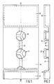
- Figure 1 is plan view of a part of a holder for syringes according to the invention;
- Figure 2 is a longitudinal sectional view of the part of the holder shown in Figure 1, namely taken on the line II-II in Figure 1;
- Figure 5 is a plan view of a part of a holder for syringes according to the invention, in a different embodiment;
- Figure 6 is a cross-sectional view of the Figure 5 holder, taken on the line VI-VI in Figure 5;
- Figure 7 is a longitudinal sectional view of the part of the holder shown in Figure 5, namely taken on the line VII-VII in Figure 5; and
- Figures 3 and 4 are longitudinal sectional views of prefilled syringes which can be connected on the holder shown in Figures 1 and 2, and 5-7 respectively.
- The syringe shown in Figure 3 comprises a
barrel 11 in one end of which apiston 15 is provided and at the other end of which aninjection needle 13 covered in a sterile manner by aneedle guard 14 is connected by means of aneedle holder 19. In order for the injection liquid, enclosed between the piston and astopper 17 in the barrel, to reach the injection needle during use of the syringe, one ormore grooves 12 are recessed in the inner wall of the needle holder, broadly as described in the United States Patent Specification 4,235,235 mentioned hereinbefore. The syringe shown in Figure 4 does not comprise an injection needle upon delivery, but comprises aneedle holder 21 having a neck whose outer surface is in the form of a truncated cone and around which the separately supplied injection needle having a cap can be connected in a tightly fitting manner; a Luer cone or a Luer lock cone is often used for such a connection. Before use the neck of theneedle holder 21 is sealed in a sterile manner by means of a protectingcap 22. At the end remote from the needle or needle connection the barrel comprises afinger grip 16 which is provided with an outwardly projectingflange 31 and firmly connected to the rear edge of the barrel by means of aclamping sleeve 18. If desired, the clamping sleeve may internally comprise a radially inwardly projecting circumferential edge which engages in a circumferential groove recessed in the outer wall of the barrel. This provision, shown in Figures 3 and 4 and also termed snap connection, ensures a firm locking of the finger grip on the barrel. As is shown in Figures 3 and 4, the rear edge of the barrel engages anend edge 20 which is formed by the rear aperture of theclamping sleeve 18 and which projects slightly inwardly, that is to say with a smaller diameter that the inner diameter of the barrel. In a prefillable syringe thepiston 15 and the injection liquid between the piston and thestopper 17 are not present. - The holder, a part of which is shown in the plan view of Figure 1 and in the longitudinal sectional view of Figure 2, comprises a plurality of, for example, twenty-five,
projections 23 which are provided on astrip 24 in one straight line. Alongitudinal ridge 25 is present between the projections and the strip and additionally ensures that the syringes connected to the holder cannot sealingly adjoin the surface of the strip. The strip comprisesfinger grips shaped elements 28 having anend portion 29 together constituting a substantially cylindrical outer surface, and having a portion of reduceddiameter 30 which is connected to the strip. It is to be noted that the syringes shown in Figures 3 and 4 are not drawn to the same scale as the holder of Figures 1 and 2. The diameter of the substantially cylindrical outer surface of theend portions 29 of the cam-shaped elements 28 is slightly larger than theend edge 20 formed by the rear opening in theclamping sleeve 18 of the finger grip in the syringes shown in Figures 3 and 4. When connecting one of these syringes to aprojection 23 of the holder shown in Figures 1 and 2, the cam-shaped elements 28 slightly bend towards each other so that theend portions 29 can pass theend edge 20. After passing the end edge, the cams bend apart again as a result of their resilience till against the inner wall of the barrel, theend edge 20 of the syringe engaging in the portions of reduceddiameter 30 of the cam-shaped elements 28. In the same manner the syringe can be taken from the holder easily by exerting on the syringe a force directed away from the holder. - The holder, a part of which is shown in Figures 5-7, comprises a plurality of
projections 36, placed in pairs at the side edges of thestrip 35 of the holder. The strip comprises alongitudinal ridge 33 between the pairs of projections, additionally ensuring that the syringes connected to the holder cannot sealingly adjoin the surface of the strip. The strip may comprise finger grips, not shown in the Figures, on each end, as described in the Figures 1-2 embodiment. The strip further comprises a number ofspacers 34, distributed over the surface. The holder has been manufactured integrally, e.g. as the holder of Figures 1-2, described hereinbefore. Eachprojection 36 comprises a resilient pawl-like element which is perpendicularly provided on the surface of the strip and an inwardly projectingend edge 32. The spacers, having a basis with a substantially triangular cross-section, taper upwards. The syringes shown in Figures 3 and 4 are equally not drawn to the same scale as the holder of Figures 5-7. When connecting one of the syringes to the holder shown in Figures 5-7, theprojections 36 slightly bend outwards to allow the outer edge of theflange 31 of the syringe finger grip to pass the inwardly projectingedges 32 of a pair ofprojections 36 on both sides of the strip. Each syringe fits with its finger grip between fourspacers 34; these spacers maintain the connected syringes in spaced relationship from each other. After passage of the end edges 32, the projections move in their original position as a result of their resilience, the outer edge of the flange of the finger grip of the syringe engaging in the pawl-like elements of theprojections 36. In the same manner the syringe can be taken from the holder easily by exerting on the syringe a force directed away from the holder.
Claims (11)
Priority Applications (1)
| Application Number | Priority Date | Filing Date | Title |
|---|---|---|---|
| AT87201173T ATE65417T1 (en) | 1986-07-10 | 1987-06-18 | HOLDER FOR A NUMBER OF INJECTION SYRINGES. |
Applications Claiming Priority (2)
| Application Number | Priority Date | Filing Date | Title |
|---|---|---|---|
| NL8601799 | 1986-07-10 | ||
| NL8601799 | 1986-07-10 |
Publications (2)
| Publication Number | Publication Date |
|---|---|
| EP0253418A1 true EP0253418A1 (en) | 1988-01-20 |
| EP0253418B1 EP0253418B1 (en) | 1991-07-24 |
Family
ID=19848291
Family Applications (1)
| Application Number | Title | Priority Date | Filing Date |
|---|---|---|---|
| EP87201173A Expired - Lifetime EP0253418B1 (en) | 1986-07-10 | 1987-06-18 | Holder for a plurality of syringes |
Country Status (9)
| Country | Link |
|---|---|
| US (1) | US4801012A (en) |
| EP (1) | EP0253418B1 (en) |
| JP (1) | JPS6324956A (en) |
| AT (1) | ATE65417T1 (en) |
| CA (1) | CA1276914C (en) |
| DE (1) | DE3771601D1 (en) |
| DK (1) | DK348987A (en) |
| ES (1) | ES2022874B3 (en) |
| NO (1) | NO164155C (en) |
Cited By (3)
| Publication number | Priority date | Publication date | Assignee | Title |
|---|---|---|---|---|
| US8182769B2 (en) | 2008-04-04 | 2012-05-22 | Biomet Biologics, Llc | Clean transportation system |
| US8444620B2 (en) | 2005-02-21 | 2013-05-21 | Biomet Biologics, Llc | Method and apparatus for application of a fluid |
| US8518272B2 (en) | 2008-04-04 | 2013-08-27 | Biomet Biologics, Llc | Sterile blood separating system |
Families Citing this family (5)
| Publication number | Priority date | Publication date | Assignee | Title |
|---|---|---|---|---|
| US5900686A (en) * | 1902-09-09 | 1999-05-04 | Seiko Epson Corporation | Electric motor vehicle |
| US6257408B1 (en) * | 1999-12-02 | 2001-07-10 | David Odierno | Needle sheathing and unsheathing safety device |
| JP4926001B2 (en) * | 2007-11-06 | 2012-05-09 | 株式会社ツバキエマソン | Waterproof geared motor |
| DE102011015112A1 (en) * | 2011-03-21 | 2012-09-27 | Vetter Pharma-Fertigung GmbH & Co. KG | Container, holding device, holding system and injection aid |
| US11660255B1 (en) | 2019-12-23 | 2023-05-30 | Marco Navarro | Liquid medication dispenser |
Family Cites Families (11)
| Publication number | Priority date | Publication date | Assignee | Title |
|---|---|---|---|---|
| US934486A (en) * | 1906-09-19 | 1909-09-21 | Thorne S Walling | Holder for surgical instruments. |
| US899664A (en) * | 1908-06-22 | 1908-09-29 | Harry C Goodrich | Mount for hooks and eyes. |
| US2472028A (en) * | 1946-11-30 | 1949-05-31 | Sonco Inc | Sterilizing tray for hypodermic needles and the like |
| US3255873A (en) * | 1963-10-11 | 1966-06-14 | Propper Mfg Company Inc | Combination sealing and dispensing device |
| US3439796A (en) * | 1968-02-27 | 1969-04-22 | Intra Products Inc | Tamperproof containers |
| US3727749A (en) * | 1971-07-01 | 1973-04-17 | Graber Rogg Inc | Tamper-proof container |
| US3768635A (en) * | 1971-11-01 | 1973-10-30 | Illinois Tool Works | Needle carrier |
| US3923152A (en) * | 1974-06-21 | 1975-12-02 | Mtm Molded Prod Co | Flat pack for revolver cartridges |
| US4015709A (en) * | 1975-10-28 | 1977-04-05 | Johnson & Johnson | Syringe package |
| US4119204A (en) * | 1977-02-07 | 1978-10-10 | The Chaspec Manufacturing Co. | Restraining structure for use in containers |
| US4572371A (en) * | 1984-07-11 | 1986-02-25 | Asenbauer Donald J | Plastic holding tray for liquid sample tubes |
-
1987
- 1987-06-18 DE DE8787201173T patent/DE3771601D1/en not_active Expired - Fee Related
- 1987-06-18 AT AT87201173T patent/ATE65417T1/en not_active IP Right Cessation
- 1987-06-18 ES ES87201173T patent/ES2022874B3/en not_active Expired - Lifetime
- 1987-06-18 EP EP87201173A patent/EP0253418B1/en not_active Expired - Lifetime
- 1987-07-07 DK DK348987A patent/DK348987A/en not_active Application Discontinuation
- 1987-07-07 US US07/070,391 patent/US4801012A/en not_active Expired - Fee Related
- 1987-07-07 CA CA000541410A patent/CA1276914C/en not_active Expired - Fee Related
- 1987-07-07 NO NO872827A patent/NO164155C/en unknown
- 1987-07-07 JP JP62167947A patent/JPS6324956A/en active Granted
Non-Patent Citations (1)
| Title |
|---|
| No relevant documents have been disclosed * |
Cited By (5)
| Publication number | Priority date | Publication date | Assignee | Title |
|---|---|---|---|---|
| US8444620B2 (en) | 2005-02-21 | 2013-05-21 | Biomet Biologics, Llc | Method and apparatus for application of a fluid |
| US9028457B2 (en) | 2005-02-21 | 2015-05-12 | Biomet Biologics, Llc | Method and apparatus for application of a fluid |
| US8182769B2 (en) | 2008-04-04 | 2012-05-22 | Biomet Biologics, Llc | Clean transportation system |
| US8518272B2 (en) | 2008-04-04 | 2013-08-27 | Biomet Biologics, Llc | Sterile blood separating system |
| US9211487B2 (en) | 2008-04-04 | 2015-12-15 | Biomet Biologics, Llc | Sterile blood separating system |
Also Published As
| Publication number | Publication date |
|---|---|
| NO164155C (en) | 1990-09-05 |
| EP0253418B1 (en) | 1991-07-24 |
| US4801012A (en) | 1989-01-31 |
| DK348987D0 (en) | 1987-07-07 |
| NO872827L (en) | 1988-01-11 |
| DK348987A (en) | 1988-01-11 |
| DE3771601D1 (en) | 1991-08-29 |
| NO164155B (en) | 1990-05-28 |
| JPS6324956A (en) | 1988-02-02 |
| CA1276914C (en) | 1990-11-27 |
| ATE65417T1 (en) | 1991-08-15 |
| NO872827D0 (en) | 1987-07-07 |
| JPH0442947B2 (en) | 1992-07-15 |
| ES2022874B3 (en) | 1991-12-16 |
Similar Documents
| Publication | Publication Date | Title |
|---|---|---|
| AU683591B2 (en) | Plastic syringe with overcap | |
| EP0107873B1 (en) | Hypodermic syringe having a telescopic assembly between cartridge and medicament holder | |
| EP0764450B1 (en) | A backstop device for a syringe | |
| US3329146A (en) | Needle container | |
| US4444310A (en) | Segmented multi-product package assembly | |
| US5569191A (en) | Device for preparing a medicinal substance solution, suspension or emulsion | |
| US6361525B2 (en) | Single-use syringe | |
| CA1261219A (en) | Power syringe with volume reducing adapter | |
| EP0340880A2 (en) | Syringe | |
| US20150129442A1 (en) | Syringe storage tray | |
| EP0225951A1 (en) | Disposable safety needle sheath | |
| JPH06500939A (en) | injection unit | |
| US20020007147A1 (en) | Single-use syringe | |
| EP0071290A1 (en) | Disposable hypodermic syringe | |
| WO1991007205A1 (en) | Unit dose medicament storing and mixing system | |
| JPH01107774A (en) | Safety unit | |
| EP0253418A1 (en) | Holder for a plurality of syringes | |
| JP6240317B2 (en) | Assembly comprising an adapter and a blister for coupling to a medical container | |
| US20220001113A1 (en) | Injection device with a cap for removing a needle shield cap from a product container, and method for assembling such an injection device | |
| CN114450232A (en) | Medical device packaging and related methods | |
| JP6397900B2 (en) | Assembly for coupling adapter to medical container | |
| JP2022535723A (en) | Hollow medical container, hollow medical container with closure cap, method for manufacturing hollow medical container, and kit | |
| JPH0652837U (en) | Syringe | |
| WO1993017937A1 (en) | Separable unit dose medication container |
Legal Events
| Date | Code | Title | Description |
|---|---|---|---|
| PUAI | Public reference made under article 153(3) epc to a published international application that has entered the european phase |
Free format text: ORIGINAL CODE: 0009012 |
|
| AK | Designated contracting states |
Kind code of ref document: A1 Designated state(s): AT BE CH DE ES FR GB IT LI LU NL SE |
|
| 17P | Request for examination filed |
Effective date: 19880618 |
|
| 17Q | First examination report despatched |
Effective date: 19900201 |
|
| GRAA | (expected) grant |
Free format text: ORIGINAL CODE: 0009210 |
|
| AK | Designated contracting states |
Kind code of ref document: B1 Designated state(s): AT BE CH DE ES FR GB IT LI LU NL SE |
|
| REF | Corresponds to: |
Ref document number: 65417 Country of ref document: AT Date of ref document: 19910815 Kind code of ref document: T |
|
| ITF | It: translation for a ep patent filed |
Owner name: ING. C. GREGORJ S.P.A. |
|
| REF | Corresponds to: |
Ref document number: 3771601 Country of ref document: DE Date of ref document: 19910829 |
|
| ET | Fr: translation filed | ||
| PGFP | Annual fee paid to national office [announced via postgrant information from national office to epo] |
Ref country code: GB Payment date: 19920401 Year of fee payment: 6 |
|
| PLBE | No opposition filed within time limit |
Free format text: ORIGINAL CODE: 0009261 |
|
| STAA | Information on the status of an ep patent application or granted ep patent |
Free format text: STATUS: NO OPPOSITION FILED WITHIN TIME LIMIT |
|
| PG25 | Lapsed in a contracting state [announced via postgrant information from national office to epo] |
Ref country code: AT Effective date: 19920618 |
|
| PG25 | Lapsed in a contracting state [announced via postgrant information from national office to epo] |
Ref country code: SE Effective date: 19920619 Ref country code: ES Free format text: LAPSE BECAUSE OF EXPIRATION OF PROTECTION Effective date: 19920619 |
|
| PGFP | Annual fee paid to national office [announced via postgrant information from national office to epo] |
Ref country code: FR Payment date: 19920625 Year of fee payment: 6 |
|
| PG25 | Lapsed in a contracting state [announced via postgrant information from national office to epo] |
Ref country code: LU Free format text: LAPSE BECAUSE OF NON-PAYMENT OF DUE FEES Effective date: 19920630 Ref country code: LI Effective date: 19920630 Ref country code: CH Effective date: 19920630 Ref country code: BE Effective date: 19920630 |
|
| PGFP | Annual fee paid to national office [announced via postgrant information from national office to epo] |
Ref country code: NL Payment date: 19920630 Year of fee payment: 6 |
|
| 26N | No opposition filed | ||
| BERE | Be: lapsed |
Owner name: DUPHAR INTERNATIONAL RESEARCH B.V. Effective date: 19920630 |
|
| REG | Reference to a national code |
Ref country code: CH Ref legal event code: PL |
|
| PG25 | Lapsed in a contracting state [announced via postgrant information from national office to epo] |
Ref country code: DE Effective date: 19930302 |
|
| PG25 | Lapsed in a contracting state [announced via postgrant information from national office to epo] |
Ref country code: GB Effective date: 19930618 |
|
| PG25 | Lapsed in a contracting state [announced via postgrant information from national office to epo] |
Ref country code: NL Effective date: 19940101 |
|
| GBPC | Gb: european patent ceased through non-payment of renewal fee |
Effective date: 19930618 |
|
| NLV4 | Nl: lapsed or anulled due to non-payment of the annual fee | ||
| PG25 | Lapsed in a contracting state [announced via postgrant information from national office to epo] |
Ref country code: FR Effective date: 19940228 |
|
| REG | Reference to a national code |
Ref country code: FR Ref legal event code: ST |
|
| EUG | Se: european patent has lapsed |
Ref document number: 87201173.9 Effective date: 19930109 |
|
| REG | Reference to a national code |
Ref country code: ES Ref legal event code: FD2A Effective date: 19990601 |
|
| PG25 | Lapsed in a contracting state [announced via postgrant information from national office to epo] |
Ref country code: IT Free format text: LAPSE BECAUSE OF NON-PAYMENT OF DUE FEES;WARNING: LAPSES OF ITALIAN PATENTS WITH EFFECTIVE DATE BEFORE 2007 MAY HAVE OCCURRED AT ANY TIME BEFORE 2007. THE CORRECT EFFECTIVE DATE MAY BE DIFFERENT FROM THE ONE RECORDED. Effective date: 20050618 |