EP0249926A2 - Electric fogging apparatus - Google Patents
Electric fogging apparatus Download PDFInfo
- Publication number
- EP0249926A2 EP0249926A2 EP87108617A EP87108617A EP0249926A2 EP 0249926 A2 EP0249926 A2 EP 0249926A2 EP 87108617 A EP87108617 A EP 87108617A EP 87108617 A EP87108617 A EP 87108617A EP 0249926 A2 EP0249926 A2 EP 0249926A2
- Authority
- EP
- European Patent Office
- Prior art keywords
- fog
- canister
- housing
- electric
- cap
- Prior art date
- Legal status (The legal status is an assumption and is not a legal conclusion. Google has not performed a legal analysis and makes no representation as to the accuracy of the status listed.)
- Granted
Links
Images

Classifications
-
- A—HUMAN NECESSITIES
- A01—AGRICULTURE; FORESTRY; ANIMAL HUSBANDRY; HUNTING; TRAPPING; FISHING
- A01M—CATCHING, TRAPPING OR SCARING OF ANIMALS; APPARATUS FOR THE DESTRUCTION OF NOXIOUS ANIMALS OR NOXIOUS PLANTS
- A01M1/00—Stationary means for catching or killing insects
- A01M1/20—Poisoning, narcotising, or burning insects
- A01M1/2022—Poisoning or narcotising insects by vaporising an insecticide
- A01M1/2061—Poisoning or narcotising insects by vaporising an insecticide using a heat source
- A01M1/2077—Poisoning or narcotising insects by vaporising an insecticide using a heat source using an electrical resistance as heat source
-
- A—HUMAN NECESSITIES
- A61—MEDICAL OR VETERINARY SCIENCE; HYGIENE
- A61L—METHODS OR APPARATUS FOR STERILISING MATERIALS OR OBJECTS IN GENERAL; DISINFECTION, STERILISATION OR DEODORISATION OF AIR; CHEMICAL ASPECTS OF BANDAGES, DRESSINGS, ABSORBENT PADS OR SURGICAL ARTICLES; MATERIALS FOR BANDAGES, DRESSINGS, ABSORBENT PADS OR SURGICAL ARTICLES
- A61L9/00—Disinfection, sterilisation or deodorisation of air
- A61L9/015—Disinfection, sterilisation or deodorisation of air using gaseous or vaporous substances, e.g. ozone
- A61L9/02—Disinfection, sterilisation or deodorisation of air using gaseous or vaporous substances, e.g. ozone using substances evaporated in the air by heating or combustion
- A61L9/03—Apparatus therefor
Definitions
- This invention relates generally to an electric fogger apparatus for fogging materials such as insecticides, deodorants, perfumes, disinfectants, and air fresheners.
- a wide variety of electric devices are known in the art for dispensing of insecticides.
- the known electric devices are, for the most part, complex devices which are expensive to manufacture and do not provide for ease of operation by the user.
- the majority of electric devices require that the user return to the device and turn the device off after the insecticide is released or require that the user physically handle the insecticide material.
- Electric devices which plug directly into the wall, such as U.S. Patent No. 4,39l,78l, assigned to S. C. Johnson & Son, Inc., containing an insecticide impregnated mat which is inserted into the housing of the device adjacent to an electric heater for generating a sustained level of insecticide to the atmosphere.
- This type of device while extremely useful for certain applications, requires that the consumer insert an insecticide impregnated mat into the device, plug the device into an electric outlet, and return and remove the device from the electric outlet after the insecticide is dispensed. While having been found useful and successful for certain applications, such devices preclude the use of larger amounts of an insecticide, do not allow the user to avoid handling the insecticide, and do not turn off automatically after the insecticide has been dispensed.
- Electric insecticide generators are also known in the art having more complex constructions and which are plugged into an electric outlet by means of an electric cord and plug such as disclosed in U.S. Patent Nos. 2,675,293; 2,685,020; 2,767,5ll and 2,690,500.
- These patents disclose complex structures which are expensive to manufacture, inconvenient to use in many circumstances, and potentially unsafe.
- the insecticide of these devices is exposed directly to the user, allowing for possible spilling of the insecticide or burning of the user. Further, after generation of the insecticide is complete, the user must manually turn the devices off.
- Electric insecticide generators are known in the art, such as U.S. Patent No. 2,660,828, which use a timer wherein the timer is present to open the electric circuit to turn off the device.
- Cooking applicances are also known in the art such as U.S. Patent Nos. 2,543,052 and 2,269,689, in which a pot or pan activates the appliance or is locked to the appliance.
- U.S. Patent Nos. 2,543,052 and 2,269,689 in which a pot or pan activates the appliance or is locked to the appliance.
- fog-producing materials are known in the art.
- U.S. Patent No. 4,l63,038 discloses the use of a mixture of a fog-producing material, such as an insecticide, a fungicide, an antiseptic, a plant growth regulant, a herbicide, or a repellant, and a blowing agent in an electric device for dispensing the fog-producing material.
- the object of the present invention is to overcome the disadvantages of the devices of the prior art, including those mentioned above, and to provide a relatively simple electric fogger for the fogging of an insecticide or other evaporable material.
- the present invention provides an electric fogging apparatus comprising: a housing means for containing a fog-producing material and constructed of a material which will transfer heat to said fog-producing material, electrical heating means in said housing for heating said fog-producing material, and means to allow for the release of a fog from said apparatus, characterized by said means for containing a fog-producing material comprising a canister for removable insertion into said housing comprising a container for containing said fog-producing material, a cap attached to said container, said cap having an opening, one or more lugs extending from said cap for locking said canister into said housing, a means on said housing for receiving and replaceably holding said canister in said housing; electrical timing means within said housing which controls said heating means whereby said heating means is operated for a predetermined period of time; and electrical switch means constructed and arranged with said timing means and said heating means for activating said timing means and said heating means, said switch means being activated by one of said lugs on said canister
- the present invention also provides a fog-producing canister for use in an electric fogger characterized by a container having an open top which holds a fog-producing material and which is constructed of a material which will transfer heat from a heat source to said fog-producing material; and a cap attached to said container for covering said container having an opening to allow the release of a fog and having at least one lug extending from said cap for activating said electric fogger.
- the present invention also provides a fog-producing canister for use in an electric fogger characterized by a container having an open top which holds a fog-producing material and which is constructed of a material which will transfer heat from a heat source to said fog-producing material; and a cap attached to said container for covering said container having an opening to allow the release of a fog and having at least one lug extending from said cap for activating said electric fogger.
- the canister will prevent the release or spitting of any unevaporated fog-producing material.
- the cap has an opening with baffle means constructed and arranged therewith to allow the release of the fog but which prevents the release of any unevaporated fog-producing material.
- the baffle prevents any active material from falling out of the canister if the canister is inverted before or during activation. Also, the baffle prevents the addition of extraneous materials into the canister.
- the baffle means may comprise a cylindrical wall extending downwardly from the top of the cap and spoke members extending outwardly from the cylindrical wall to converge at and connect to an inner inverted cup. The spoke members extend below each of the cylindrical wall and inverted cup and are connected to a horizontally disposed ring member.
- the configuration of the baffle means provides indirect opening to the environment of use and thus prevents the spitting or release of any unevaporated fog-producing material, such as an insecticide, to the environment of use while allowing for the release of fogged material.
- fog-producing means a composition which evaporates upon heating or which undergoes a chemical reaction or decomposition of at least one component to produce a fog or aerosol to carry an active agent to the atmosphere.
- fog-producing materials include insecticides, repellants, perfumes, deodorants, disinfectants, etc.
- Preferred fog-producing materials are disclosed in U.S. Patent No. 4,l63,038.
- the electric fogger of the present invention comprises a housing l0 and disposable canister 90.
- housing l0 comprises a top 20 and a base 40.
- Housing l0 contains secured therein, as described more fully hereinafter, pivoting cam 80, printed circuit board 70 (hereafter "PC board”), hot plate 60, electrical wires l2 connecting PC board 70 to hot plate 60 (not shown), and electrical cord l4 and plug (not shown) for insertion into an electrical outlet and connected to PC board 70 (not shown) for providing electricity to the fogger.
- PC board printed circuit board 70
- Top 20 and base 40 of housing l0 are made of any suitable material such as plastic or metal, a preferred material being plastic.
- Top 20 and base 40 are made by any conventional molding process and are constructed and arranged to mate together by any suitable fastening means. In the preferred embodiment, the fastening means are screws.
- Top 20 of housing l0 is shown in top view in Figure l and in bottom view in Figure 2.
- top 20 includes an outer surface 2l and side walls 22.
- Side walls 22 include grid openings 23 for ventilation of the heat generated from hot plate 60.
- Top 20 further includes an opening 24 for receiving and replaceably holding canister 90.
- Opening 24 is shown and described in its preferred embodiment as being circular, although the configuration of the opening may be modified.
- Opening 24 has a neck 25 protruding outwardly and upwardly from surface 2l. Attached to neck 25 is an annular ring 26 through legs 27. Neck 25, legs 27 and ring 26 provide for openings 28 for additional ventilation of heat generated by hot plate 60.
- Extending inwardly from ring 26 are flanges 29 for receiving and supporting canister 90. Flanges 29 are spaced sufficiently apart from one another to provide openings 30 for receiving lugs 96 of canister 90.
- Housing l0 contains a window 3l for transmission of a light source 76 from printed circuit board 70 to indicate when the electric fogger is in operation.
- top 20 is seen in bottom view with canister 90 shown inserted and rotated in the housing to activate the electric fogger and lock canister 90 into position.
- a plurality of stops 32 extend downwardly from flanges 29. Stops 32 are constructed to permit canister 90 to be rotated in only one direction and to seat lugs 96 after being rotated approximately l/6th of a turn. Rotation of the canister only a predetermined distance is essential to activate the electric fogger by having one of lugs 96 contact pivoting cam 80 which in turn contacts leaf spring 72 on PC board 70 to close the electrical circuit. Further, the stop members aid in locking the canister into the housing.
- Flanges 29 further include a plurality of detents 33 for receiving and seating lugs 96.
- Lugs 96 will be positioned in detents 33 when the canister is rotated approximately l/6th of a turn thereby activating the canister and locking the canister into the housing.
- Top 20 further includes a heat shield 34 which surrounds hot plate 60 and mates with heat shield 43 of base 40.
- the shield serves to retain the heat from hot plate 60 within a confined area and to direct the heat to the canister 90.
- Bosses 35 are provided for fastening top 20 to base 40 by screws (not shown), or any other suitable fastening means, and are located in top 20 in mating relation to corresponding bosses 42 in base 40.
- Vertical walls 36 and guide channels 37 are provided for receiving and holding PC board 70 in place in the housing.
- Slot 38 is provided for receiving and holding the top of pivoting cam 80 in the housing.
- Base 40 of housing l0 is shown in Figure l. As described above, the base 40 mates with the top 20. Similar to top 20 base 40 is generally rectangular and contains a bottom surface and side walls. Ventilation grid openings 4l are located in the sides of base 40 for ventilation of heat generated from hot plate 60. A ventilation grid opening is preferably also located in the bottom of the base 40 (not shown).
- Base 40 includes bosses 42 which mate with bosses 35 of top 20 through which screws (not shown) are inserted for fastening base 40 to top 20.
- the base has a heat shield 43 which serves to receive, support, and surround hot plate 60. Notches 44 are provided in shield 43 for receiving arms 64 of hot plate 60.
- a hollow column 45 is located adjacent to shield 43 and PC board 70 for receiving and supporting pivoting cam 80.
- Vertical walls 46 with guide channels (not shown) are provided in base 40 for receiving and holding PC board 70 in position in the housing.
- Electric heating elements are generally known in the art and any conventional heating element may be used in conjunction with the invention.
- a preferred heating element is a hot plate.
- Hot plate 60 comprises a light-weight metal plate 62 with arms 64 and heater 66.
- Heater 66 is attached to metal plate 62 by any suitable fastening means and may be any conventional electric heater known in the art, for example a TDK® Model No. 500l heater has been found to work well, also a rope heater can be used.
- Electrical wires l2 attached to electrical contacts (not shown) on PC board 70, are attached to electrical contacts (not shown) on the underside of heater 66 and deliver electric current to the heater to energize the heater.
- PC board 70 controls the electric current delivered to the heater.
- PC board 70 is a conventional printed circuit board known in the art and is adapted to operate and control the electric current delivered to heater 66.
- the PC board serves to turn the heater “on” by means of an electrical switch attached to the PC board and turn the heater “off” by means of a timer incorporated in the PC board.
- a timer is incorporated in the PC board to control the period of time which the heater 66 is in operation. Any conventional timer known in the art may be incorporated in the PC board. The timed period is adjusted to correspond to the amount of time needed to evaporate the insecticide in canister 90.
- a conventional electric cord l4 and plug (not shown) is attached to electric contacts on the PC board to provide electric current to the fogger. The electric cord l4 is plugged into a conventional electric outlet.
- the PC board may use a conventional electrical switch known in the art for closing an electrical circuit and to deliver electricity to the fogger.
- a preferred electrical switch for closing the electrical circuit and turning the device “on” is leaf spring 72 and contact 74.
- leaf spring 72 When leaf spring 72 is placed in electrical contact with contact 74, the electrical circuit is closed and the PC board energizes heater 66.
- a timer on the PC board (not shown) is set for a predetermined period of time which upon expiration will break the electrical circuit thereby turning "off" the heater 66.
- PC board 70 also may include a light source 76 which is positioned adjacent to window 3l for indicating when the device is in operation.
- pivoting cam 80 is located adjacent to PC board 70 and serves to close the electrical circuit upon insertion and rotation of canister 90 by moving leaf spring 72 into electrical contact with contact 74 thereby turning "on" the electric fogger.
- Pivoting cam 80 is secured in the housing by column 45 of base 40 and slot 38 of top 20.
- Pivoting cam 80 includes a cam post 82 which is generally cylindrical for insertion in cam support column 45 and retaining slot 38.
- Cam post 82 may include support arms 84 extending outwardly and away from cam post 82 for supporting the pivoting cam on column 45 and for supporting cam arm 86.
- Cam arm 86 is generally L-shaped and has a finger 87 for contacting leaf spring 72 to close the electrical circuit and has a concave vertical wall camming surface 88 opposite of finger 87 for engagement with lug 96.
- a lug 96 of canister 90 will contact camming surface 88 to pivot the cam post 82 in column 45 thereby pivoting cam arm 86 into contact with leaf spring 72 to close the electrical circuit and energize the fogger.
- the lug 96 will remain in contact with camming surface 88 keeping the electrical circuit closed until the canister is removed by the user.
- the electrical circuit will be broken by a timer incorporated in the PC board after a pre-determined period of time thereby automatically turning the fogger "off".
- Canister 90 is comprised of a container 9l, preferably made of a light-weight metal, and a cap 92, preferably made of plastic.
- the canister may contain any suitable fog-producing or evaporable material known in the art such as an insecticide, a deodorant, a perfume, a disinfectant, or an air freshener for fogging or dispensing upon exposure to heat.
- the container 9l must be capable of receiving heat and transferring the heat to the material in container 9l.
- the cap 92 is attached to the container by conventional means.
- Cap 92 has ribs 93 for rotating the canister after insertion in the housing to activate the electric fogger and to lock the canister into position in the housing.
- Cap 92 has a small opening 94 in the center of the cap for release of the material.
- cap 92 includes collar members 95 extending from the cap for seating on flanges 29 of top 20.
- Cap 92 also includes lugs 96 extending from the base of cap 92. The lugs 96 serve to simultaneously activate the electric fogger by contacting pivoting cam 80 to close the electrical circuit and to lock the canister into the housing.
- the canister is inserted into the housing l0 by inserting lugs 96 through openings 30 and collars 95 seat on flanges 29.
- the canister is rotated approximately l/6th of a turn whereby one of lugs 96 will activate the electric fogger by contacting pivoting cam 80 which closes the electrical circuit.
- Lugs 96 in conjunction with collars 95 and flange 29 serve to lock the canister into the housing.
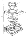
- Figure 4 illustrates a second preferred embodiment of the invention described above.
- the embodiment shown in Figure 4 uses generally the same components as the electric fogger shown in Figure l and operates on the same principles as the electric fogger shown in Figure l.
- the housing l00 and canister ll0, as shown in Figures 5, 6, 7 and 8 are of a modified construction than the housing l0 and canister 90 of Figure l. Since the housing l00 and its component parts shown in Figure 4 are es sentially the same as those previously described for the electric fogger shown in Figure l, the description will not be repeated, it being understood that the electric fogger shown in Figure 4 is constructed and operates on the same principles as the electric fogger shown in Figure l.
- canister ll0 includes a container lll, preferably made of a light-weight metal, and a cap ll2, preferably made of plastic or any other suitable material.
- the canister may contain any suitable fog-producing or evaporable material known in the art such as an insecticide, a deodorant, a perfume, a disinfectant, or an air freshener for dispensing upon exposure to heat.
- the container must be capable of receiving heat and transferring the heat to the material contained therein.
- the cap is preferably made of plastic by conventional molding processes.
- Container lll is attached to cap ll2 by means of a lip ll3 surrounding the periphery of the container which catches on a ledge ll4 on the inside of cap ll2.
- Cap ll2 includes a baffle opening ll5 which prevents the spitting of any unevaporated fog-producing material from the canister while allowing for the release of the fogged material.
- Baffle opening ll5 includes a cylindrical wall ll6, as best shown in Figures 5 and 7, extending downwardly from the top of the cap having an open top and bottom.
- Extending outwardly from cylindrical wall ll6 are spokes ll7 which converge at and connect to an inner inverted cup ll8.
- Spokes ll7 extend below each of cylindrical wall ll6 and inverted cup ll8.
- Connected at the bottom of spokes ll7 is a horizontally disposed ring ll9 which is arranged to provide a space between it and the inverted cup ll8.
- Baffle opening ll5 provides a configuration which prevents the spitting of any insecticide, or other fog-producing material, while allowing release of the fogged material. Also, wall ll6 prevents the release of any liquid if the canister is tipped or inverted.
- Cap ll2 also includes collars l20 extending outwardly from the cap for seating on flanges 29 of the housing as described above. Further, cap ll2 includes lugs l2l extending outwardly from the cap for activating the electric fogger and locking the canister into the housing of the electric fogger as described above. Lugs l2l further include nipples l22 protruding from the lugs for contacting pivoting cam l8 and for seating in detents 33.
- canister ll0 may be used in electric foggers having a separate power and timer means.
- cap ll2 has a second set of lugs l23 extending outwardly from cap ll2 and constructed and arranged below lugs l2l.
- Lugs l23 are provided to activate a second electrical switch.
- housing l00 may include a power source activated by a first electrical switch and a timer means activated by a second electrical switch.
- lugs l2l upon insertion and rotation of canister ll0, lugs l2l will activate the first electrical switch to turn the fogger "on" and lugs l23 will activate the second electrical switch to set the timer means, the timer means being constructed to open the electrical circuit after a predetermined period of time.
- lugs 96 will pivot cam 80 into contact with leaf spring 72 thereby closing the electrical circuit on PC board 70 allowing the electric current to pass to heater 66 thereby activating the electric fogger.
- Rotation of canister 90 simultaneously activates the electric fogger and locks the canister into the housing as lugs 96 are seated in detents 33 beneath flanges 29 and collars 95 are seated on top of flanges 29 thereby holding the canister in the housing.
- the hot plate will then heat up and provide heat to container 9l of the canister which is transferred to the fog-producing material in the container thereby causing evaporation of fog-producing material to produce a fog which is released through opening 94 to the environment of use.
- the timer of PC board 70 is set to correspond to the amount of time required to completely fog the fog-producing material and at the end of such period will automatically break the electrical circuit thereby turning the heater "off.”
- the fogger automatically turns off allowing the user to return and remove the exhausted canister at his convenience.
- the exhausted canister is removed by rotation of the canister counter-clockwise and is disposed of. The fogger is then ready for the insertion of a new canister.
- the electric fogger may utilize canister ll0 having baffle opening ll5 which prevents the spitting of unevaporated insecticide into the environment of use while allowing the release of the fogged material.
- Canister ll0 is a preferred embodiment for the disposable canisters.
- the above-described invention provides an electric fogger which is inexpensive to manufacture and easy and safe to use.
- the electric fogger avoids user contact with the fog-producing material and allows the user to activate the fogger and leave the room knowing that the device will turn "off" automatically upon complete fogging of the fog-producing material. While the preferred embodiments of the device have been described in detail above, various modifications and variations of the invention are possible in light of the above teachings.
Abstract
Description
- This invention relates generally to an electric fogger apparatus for fogging materials such as insecticides, deodorants, perfumes, disinfectants, and air fresheners.
- A wide variety of electric devices are known in the art for dispensing of insecticides. However, the known electric devices are, for the most part, complex devices which are expensive to manufacture and do not provide for ease of operation by the user. Specifically, the majority of electric devices require that the user return to the device and turn the device off after the insecticide is released or require that the user physically handle the insecticide material.
- Electric devices are known which plug directly into the wall, such as U.S. Patent No. 4,39l,78l, assigned to S. C. Johnson & Son, Inc., containing an insecticide impregnated mat which is inserted into the housing of the device adjacent to an electric heater for generating a sustained level of insecticide to the atmosphere. This type of device, while extremely useful for certain applications, requires that the consumer insert an insecticide impregnated mat into the device, plug the device into an electric outlet, and return and remove the device from the electric outlet after the insecticide is dispensed. While having been found useful and successful for certain applications, such devices preclude the use of larger amounts of an insecticide, do not allow the user to avoid handling the insecticide, and do not turn off automatically after the insecticide has been dispensed.
- Electric insecticide generators are also known in the art having more complex constructions and which are plugged into an electric outlet by means of an electric cord and plug such as disclosed in U.S. Patent Nos. 2,675,293; 2,685,020; 2,767,5ll and 2,690,500. These patents disclose complex structures which are expensive to manufacture, inconvenient to use in many circumstances, and potentially unsafe. For example, the insecticide of these devices is exposed directly to the user, allowing for possible spilling of the insecticide or burning of the user. Further, after generation of the insecticide is complete, the user must manually turn the devices off.
- Electric insecticide generators are known in the art, such as U.S. Patent No. 2,660,828, which use a timer wherein the timer is present to open the electric circuit to turn off the device. Cooking applicances are also known in the art such as U.S. Patent Nos. 2,543,052 and 2,269,689, in which a pot or pan activates the appliance or is locked to the appliance. However, these prior art devices are generally complex and expensive to manufacture, and impractical to use.
- Further, fog-producing materials are known in the art. For example, U.S. Patent No. 4,l63,038 discloses the use of a mixture of a fog-producing material, such as an insecticide, a fungicide, an antiseptic, a plant growth regulant, a herbicide, or a repellant, and a blowing agent in an electric device for dispensing the fog-producing material.
- The object of the present invention is to overcome the disadvantages of the devices of the prior art, including those mentioned above, and to provide a relatively simple electric fogger for the fogging of an insecticide or other evaporable material.
- The present invention provides an electric fogging apparatus comprising: a housing means for containing a fog-producing material and constructed of a material which will transfer heat to said fog-producing material, electrical heating means in said housing for heating said fog-producing material, and means to allow for the release of a fog from said apparatus, characterized by said means for containing a fog-producing material comprising a canister for removable insertion into said housing comprising a container for containing said fog-producing material, a cap attached to said container, said cap having an opening, one or more lugs extending from said cap for locking said canister into said housing, a means on said housing for receiving and replaceably holding said canister in said housing; electrical timing means within said housing which controls said heating means whereby said heating means is operated for a predetermined period of time; and electrical switch means constructed and arranged with said timing means and said heating means for activating said timing means and said heating means, said switch means being activated by one of said lugs on said canister upon insertion and rotation of said canister in said receiving and holding means of said housing; thereby heating said canister, the heat being transferred to said fog-producing material to produce a fog which is released to an environment to use through the opening in said canister cap.
- The present invention also provides a fog-producing canister for use in an electric fogger characterized by a container having an open top which holds a fog-producing material and which is constructed of a material which will transfer heat from a heat source to said fog-producing material; and a cap attached to said container for covering said container having an opening to allow the release of a fog and having at least one lug extending from said cap for activating said electric fogger.
- The present invention also provides a fog-producing canister for use in an electric fogger characterized by a container having an open top which holds a fog-producing material and which is constructed of a material which will transfer heat from a heat source to said fog-producing material; and a cap attached to said container for covering said container having an opening to allow the release of a fog and having at least one lug extending from said cap for activating said electric fogger.
- In a preferred embodiment the canister will prevent the release or spitting of any unevaporated fog-producing material. The cap has an opening with baffle means constructed and arranged therewith to allow the release of the fog but which prevents the release of any unevaporated fog-producing material. Additionally, the baffle prevents any active material from falling out of the canister if the canister is inverted before or during activation. Also, the baffle prevents the addition of extraneous materials into the canister. The baffle means may comprise a cylindrical wall extending downwardly from the top of the cap and spoke members extending outwardly from the cylindrical wall to converge at and connect to an inner inverted cup. The spoke members extend below each of the cylindrical wall and inverted cup and are connected to a horizontally disposed ring member. The configuration of the baffle means provides indirect opening to the environment of use and thus prevents the spitting or release of any unevaporated fog-producing material, such as an insecticide, to the environment of use while allowing for the release of fogged material.
- As used in the present invention, the term "fog-producing" means a composition which evaporates upon heating or which undergoes a chemical reaction or decomposition of at least one component to produce a fog or aerosol to carry an active agent to the atmosphere. Examples of fog-producing materials include insecticides, repellants, perfumes, deodorants, disinfectants, etc. Preferred fog-producing materials are disclosed in U.S. Patent No. 4,l63,038.
- In the drawings:
- Figure l is an exploded view of one embodiment of the invention;
- Figure 2 is a bottom view of the top member of the housing in receipt of the canister;
- Figure 3 appearing on the second sheet of the drawings is a top partially cut away view of the electric fogger shown being activated by the canister;
- Figure 4 appearing on the third sheet of the drawings is an exploded view of a second embodiment of the invention;
- Figure 5 is an exploded view of a preferred embodiment of the canister;
- Figure 6 is a top view of a preferred embodiment of the cap of the canister;
- Figure 7 is a cross-section of a preferred embodiment of the cap of the canister taken along line 7-7 of Figure 6.
- Figure 8 is a bottom view of the cap of a preferred embodiment of the canister.
- Figure 9 is a plan view of the pivoting cam.
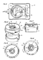
- Referring to Figure l, the electric fogger of the present invention comprises a housing l0 and
disposable canister 90. Generally, housing l0 comprises atop 20 and abase 40. Housing l0 contains secured therein, as described more fully hereinafter,pivoting cam 80, printed circuit board 70 (hereafter "PC board"),hot plate 60, electrical wires l2 connectingPC board 70 to hot plate 60 (not shown), and electrical cord l4 and plug (not shown) for insertion into an electrical outlet and connected to PC board 70 (not shown) for providing electricity to the fogger. - Top 20 and
base 40 of housing l0 are made of any suitable material such as plastic or metal, a preferred material being plastic. Top 20 andbase 40 are made by any conventional molding process and are constructed and arranged to mate together by any suitable fastening means. In the preferred embodiment, the fastening means are screws. - Top 20 of housing l0 is shown in top view in Figure l and in bottom view in Figure 2. Referring to Figure l,
top 20 includes an outer surface 2l andside walls 22.Side walls 22 includegrid openings 23 for ventilation of the heat generated fromhot plate 60. - Top 20 further includes an opening 24 for receiving and replaceably holding
canister 90.Opening 24 is shown and described in its preferred embodiment as being circular, although the configuration of the opening may be modified.Opening 24 has a neck 25 protruding outwardly and upwardly from surface 2l. Attached to neck 25 is anannular ring 26 throughlegs 27. Neck 25,legs 27 andring 26 provide foropenings 28 for additional ventilation of heat generated byhot plate 60. Extending inwardly fromring 26 areflanges 29 for receiving and supportingcanister 90.Flanges 29 are spaced sufficiently apart from one another to provideopenings 30 for receivinglugs 96 ofcanister 90. - Housing l0 contains a window 3l for transmission of a
light source 76 fromprinted circuit board 70 to indicate when the electric fogger is in operation. - Referring to Figure 2,
top 20 is seen in bottom view withcanister 90 shown inserted and rotated in the housing to activate the electric fogger andlock canister 90 into position. A plurality ofstops 32 extend downwardly fromflanges 29.Stops 32 are constructed to permitcanister 90 to be rotated in only one direction and to seatlugs 96 after being rotated approximately l/6th of a turn. Rotation of the canister only a predetermined distance is essential to activate the electric fogger by having one oflugs 96contact pivoting cam 80 which in turncontacts leaf spring 72 onPC board 70 to close the electrical circuit. Further, the stop members aid in locking the canister into the housing. -
Flanges 29 further include a plurality ofdetents 33 for receiving andseating lugs 96.Lugs 96 will be positioned indetents 33 when the canister is rotated approximately l/6th of a turn thereby activating the canister and locking the canister into the housing. -
Top 20 further includes aheat shield 34 which surroundshot plate 60 and mates with heat shield 43 ofbase 40. The shield serves to retain the heat fromhot plate 60 within a confined area and to direct the heat to thecanister 90. -
Bosses 35 are provided for fastening top 20 tobase 40 by screws (not shown), or any other suitable fastening means, and are located in top 20 in mating relation to correspondingbosses 42 inbase 40.Vertical walls 36 and guidechannels 37 are provided for receiving and holdingPC board 70 in place in the housing.Slot 38 is provided for receiving and holding the top of pivotingcam 80 in the housing. -
Base 40 of housing l0 is shown in Figure l. As described above, the base 40 mates with the top 20. Similar to top 20base 40 is generally rectangular and contains a bottom surface and side walls. Ventilation grid openings 4l are located in the sides ofbase 40 for ventilation of heat generated fromhot plate 60. A ventilation grid opening is preferably also located in the bottom of the base 40 (not shown). -
Base 40 includesbosses 42 which mate withbosses 35 of top 20 through which screws (not shown) are inserted forfastening base 40 totop 20. The base has a heat shield 43 which serves to receive, support, and surroundhot plate 60.Notches 44 are provided in shield 43 for receivingarms 64 ofhot plate 60. Ahollow column 45 is located adjacent to shield 43 andPC board 70 for receiving and supportingpivoting cam 80.Vertical walls 46 with guide channels (not shown) are provided inbase 40 for receiving and holdingPC board 70 in position in the housing. - Electric heating elements are generally known in the art and any conventional heating element may be used in conjunction with the invention. A preferred heating element is a hot plate.
Hot plate 60 comprises a light-weight metal plate 62 witharms 64 andheater 66.Heater 66 is attached tometal plate 62 by any suitable fastening means and may be any conventional electric heater known in the art, for example a TDK® Model No. 500l heater has been found to work well, also a rope heater can be used. Electrical wires l2, attached to electrical contacts (not shown) onPC board 70, are attached to electrical contacts (not shown) on the underside ofheater 66 and deliver electric current to the heater to energize the heater.PC board 70 controls the electric current delivered to the heater. - Referring again to Figure l,
PC board 70 is a conventional printed circuit board known in the art and is adapted to operate and control the electric current delivered toheater 66. The PC board serves to turn the heater "on" by means of an electrical switch attached to the PC board and turn the heater "off" by means of a timer incorporated in the PC board. Specifically, a timer is incorporated in the PC board to control the period of time which theheater 66 is in operation. Any conventional timer known in the art may be incorporated in the PC board. The timed period is adjusted to correspond to the amount of time needed to evaporate the insecticide incanister 90. A conventional electric cord l4 and plug (not shown) is attached to electric contacts on the PC board to provide electric current to the fogger. The electric cord l4 is plugged into a conventional electric outlet. - As best shown in Figure 3, the PC board may use a conventional electrical switch known in the art for closing an electrical circuit and to deliver electricity to the fogger.
- A preferred electrical switch for closing the electrical circuit and turning the device "on" is
leaf spring 72 andcontact 74. Whenleaf spring 72 is placed in electrical contact withcontact 74, the electrical circuit is closed and the PC board energizesheater 66. A timer on the PC board (not shown) is set for a predetermined period of time which upon expiration will break the electrical circuit thereby turning "off" theheater 66. -
PC board 70 also may include alight source 76 which is positioned adjacent to window 3l for indicating when the device is in operation. - Referring to Figures l and 9, pivoting
cam 80 is located adjacent toPC board 70 and serves to close the electrical circuit upon insertion and rotation ofcanister 90 by movingleaf spring 72 into electrical contact withcontact 74 thereby turning "on" the electric fogger. Pivotingcam 80 is secured in the housing bycolumn 45 ofbase 40 andslot 38 oftop 20. Pivotingcam 80 includes acam post 82 which is generally cylindrical for insertion incam support column 45 and retainingslot 38. Cam post 82 may includesupport arms 84 extending outwardly and away from cam post 82 for supporting the pivoting cam oncolumn 45 and for supportingcam arm 86.Cam arm 86 is generally L-shaped and has afinger 87 for contactingleaf spring 72 to close the electrical circuit and has a concave verticalwall camming surface 88 opposite offinger 87 for engagement withlug 96. In activating the fogger as shown in Figure 3, alug 96 ofcanister 90 will contactcamming surface 88 to pivot thecam post 82 incolumn 45 thereby pivotingcam arm 86 into contact withleaf spring 72 to close the electrical circuit and energize the fogger. Thelug 96 will remain in contact withcamming surface 88 keeping the electrical circuit closed until the canister is removed by the user. As described above, the electrical circuit will be broken by a timer incorporated in the PC board after a pre-determined period of time thereby automatically turning the fogger "off". -
Canister 90, as best shown in Figures l and 3, is comprised of a container 9l, preferably made of a light-weight metal, and acap 92, preferably made of plastic. The canister may contain any suitable fog-producing or evaporable material known in the art such as an insecticide, a deodorant, a perfume, a disinfectant, or an air freshener for fogging or dispensing upon exposure to heat. The container 9l must be capable of receiving heat and transferring the heat to the material in container 9l. Thecap 92 is attached to the container by conventional means.Cap 92 hasribs 93 for rotating the canister after insertion in the housing to activate the electric fogger and to lock the canister into position in the housing.Cap 92 has asmall opening 94 in the center of the cap for release of the material. - As also seen in Figures l and 3,
cap 92 includescollar members 95 extending from the cap for seating onflanges 29 oftop 20.Cap 92 also includeslugs 96 extending from the base ofcap 92. Thelugs 96 serve to simultaneously activate the electric fogger by contacting pivotingcam 80 to close the electrical circuit and to lock the canister into the housing. - As seen in Figures 2 and 3, the canister is inserted into the housing l0 by inserting
lugs 96 throughopenings 30 andcollars 95 seat onflanges 29. The canister is rotated approximately l/6th of a turn whereby one oflugs 96 will activate the electric fogger by contacting pivotingcam 80 which closes the electrical circuit.Lugs 96 in conjunction withcollars 95 andflange 29 serve to lock the canister into the housing. - Figure 4 illustrates a second preferred embodiment of the invention described above. The embodiment shown in Figure 4 uses generally the same components as the electric fogger shown in Figure l and operates on the same principles as the electric fogger shown in Figure l. However, the housing l00 and canister ll0, as shown in Figures 5, 6, 7 and 8 are of a modified construction than the housing l0 and
canister 90 of Figure l. Since the housing l00 and its component parts shown in Figure 4 are es sentially the same as those previously described for the electric fogger shown in Figure l, the description will not be repeated, it being understood that the electric fogger shown in Figure 4 is constructed and operates on the same principles as the electric fogger shown in Figure l. - Referring to Figures 5, 6, 7 and 8, canister ll0 includes a container lll, preferably made of a light-weight metal, and a cap ll2, preferably made of plastic or any other suitable material. The canister may contain any suitable fog-producing or evaporable material known in the art such as an insecticide, a deodorant, a perfume, a disinfectant, or an air freshener for dispensing upon exposure to heat. The container must be capable of receiving heat and transferring the heat to the material contained therein. The cap is preferably made of plastic by conventional molding processes. Container lll is attached to cap ll2 by means of a lip ll3 surrounding the periphery of the container which catches on a ledge ll4 on the inside of cap ll2. Cap ll2 includes a baffle opening ll5 which prevents the spitting of any unevaporated fog-producing material from the canister while allowing for the release of the fogged material. Baffle opening ll5 includes a cylindrical wall ll6, as best shown in Figures 5 and 7, extending downwardly from the top of the cap having an open top and bottom. Extending outwardly from cylindrical wall ll6 are spokes ll7 which converge at and connect to an inner inverted cup ll8. Spokes ll7 extend below each of cylindrical wall ll6 and inverted cup ll8. Connected at the bottom of spokes ll7 is a horizontally disposed ring ll9 which is arranged to provide a space between it and the inverted cup ll8. Baffle opening ll5 provides a configuration which prevents the spitting of any insecticide, or other fog-producing material, while allowing release of the fogged material. Also, wall ll6 prevents the release of any liquid if the canister is tipped or inverted.
- Cap ll2 also includes collars l20 extending outwardly from the cap for seating on
flanges 29 of the housing as described above. Further, cap ll2 includes lugs l2l extending outwardly from the cap for activating the electric fogger and locking the canister into the housing of the electric fogger as described above. Lugs l2l further include nipples l22 protruding from the lugs for contacting pivoting cam l8 and for seating indetents 33. - Referring again to Figures 5 through 8, canister ll0 may be used in electric foggers having a separate power and timer means. For use in such an embodiment, cap ll2 has a second set of lugs l23 extending outwardly from cap ll2 and constructed and arranged below lugs l2l. Lugs l23 are provided to activate a second electrical switch. For example, when a PC board is not used, the electric fogger may use a separate timer means and power source. In such a case, housing l00 may include a power source activated by a first electrical switch and a timer means activated by a second electrical switch. Thus for example, upon insertion and rotation of canister ll0, lugs l2l will activate the first electrical switch to turn the fogger "on" and lugs l23 will activate the second electrical switch to set the timer means, the timer means being constructed to open the electrical circuit after a predetermined period of time.
- Having described the preferred embodiments of the invention, the operation of the electric fogger will now be described in reference to the embodiment shown in Figures l-3. To use the electric fogger described herein, the user plugs electric cord l4 into an electric outlet.
Canister 90 is then inserted into housing l0 after lining up lugs 96 withopenings 30.Collars 95 ofcanister 90 seat on and overlieflanges 29 of housing l0.Canister 90 is rotated. clockwise approximately l/6th of a turn whereby lugs 96 are seated indetents 33 as shown in Figure 2. One oflugs 96 will pivotcam 80 into contact withleaf spring 72 thereby closing the electrical circuit onPC board 70 allowing the electric current to pass toheater 66 thereby activating the electric fogger. Rotation ofcanister 90 simultaneously activates the electric fogger and locks the canister into the housing aslugs 96 are seated indetents 33 beneathflanges 29 andcollars 95 are seated on top offlanges 29 thereby holding the canister in the housing. The hot plate will then heat up and provide heat to container 9l of the canister which is transferred to the fog-producing material in the container thereby causing evaporation of fog-producing material to produce a fog which is released throughopening 94 to the environment of use. The timer ofPC board 70 is set to correspond to the amount of time required to completely fog the fog-producing material and at the end of such period will automatically break the electrical circuit thereby turning the heater "off." After the insecticide is completely fogged, the fogger automatically turns off allowing the user to return and remove the exhausted canister at his convenience. The exhausted canister is removed by rotation of the canister counter-clockwise and is disposed of. The fogger is then ready for the insertion of a new canister. - As described above and shown in Figure 5 through 8, the electric fogger may utilize canister ll0 having baffle opening ll5 which prevents the spitting of unevaporated insecticide into the environment of use while allowing the release of the fogged material. Canister ll0 is a preferred embodiment for the disposable canisters.
- The above-described invention provides an electric fogger which is inexpensive to manufacture and easy and safe to use. The electric fogger avoids user contact with the fog-producing material and allows the user to activate the fogger and leave the room knowing that the device will turn "off" automatically upon complete fogging of the fog-producing material. While the preferred embodiments of the device have been described in detail above, various modifications and variations of the invention are possible in light of the above teachings.
Claims (12)
Priority Applications (1)
| Application Number | Priority Date | Filing Date | Title |
|---|---|---|---|
| AT87108617T ATE95668T1 (en) | 1986-06-20 | 1987-06-15 | ELECTRIC NEBULIZER. |
Applications Claiming Priority (2)
| Application Number | Priority Date | Filing Date | Title |
|---|---|---|---|
| US876584 | 1986-06-20 | ||
| US06/876,584 US4675504A (en) | 1986-06-20 | 1986-06-20 | Electric fogger |
Publications (3)
| Publication Number | Publication Date |
|---|---|
| EP0249926A2 true EP0249926A2 (en) | 1987-12-23 |
| EP0249926A3 EP0249926A3 (en) | 1989-12-27 |
| EP0249926B1 EP0249926B1 (en) | 1993-10-13 |
Family
ID=25368073
Family Applications (1)
| Application Number | Title | Priority Date | Filing Date |
|---|---|---|---|
| EP87108617A Expired - Lifetime EP0249926B1 (en) | 1986-06-20 | 1987-06-15 | Electric fogging apparatus |
Country Status (10)
| Country | Link |
|---|---|
| US (1) | US4675504A (en) |
| EP (1) | EP0249926B1 (en) |
| JP (1) | JPS633746A (en) |
| AT (1) | ATE95668T1 (en) |
| AU (1) | AU590704B2 (en) |
| BR (1) | BR8703060A (en) |
| CA (1) | CA1256926A (en) |
| DE (1) | DE3787758T2 (en) |
| ES (1) | ES2043621T3 (en) |
| PH (1) | PH23854A (en) |
Cited By (4)
| Publication number | Priority date | Publication date | Assignee | Title |
|---|---|---|---|---|
| EP0689766A1 (en) * | 1994-06-28 | 1996-01-03 | FALP S.r.l. | Apparatus for vaporizing insecticidal solutions and the like |
| WO1996028969A1 (en) * | 1995-03-20 | 1996-09-26 | Perycut-Chemie Ag | Evaporator |
| EP1055430A1 (en) * | 1999-05-27 | 2000-11-29 | FALP S.r.l. | Electric vaporizer, particularly for deodorant and insecticidal liquids and the like |
| CN1080598C (en) * | 1997-02-05 | 2002-03-13 | 大日工业株式会社 | Insecticide sprayer |
Families Citing this family (38)
| Publication number | Priority date | Publication date | Assignee | Title |
|---|---|---|---|---|
| US4795883A (en) * | 1987-07-08 | 1989-01-03 | Environmental Fragrance Technologies, Ltd. | Aroma generating apparatus and driver circuit |
| US5282334A (en) * | 1989-04-17 | 1994-02-01 | Kohichiro Kimura | Insect exterminator |
| JPH037530A (en) * | 1989-06-06 | 1991-01-14 | Haruhiko Akiyama | Heating evaporator |
| US5094025A (en) * | 1990-04-24 | 1992-03-10 | Hunting Adventures, Inc. | Animal scent heater |
| US5168654A (en) * | 1992-05-29 | 1992-12-08 | Chien Hsiu Hung | Insect-repellent device |
| USD381073S (en) * | 1995-07-11 | 1997-07-15 | S. C. Johnson & Son, Inc. | Heated device for dispensing volatile substances |
| USD381740S (en) * | 1995-11-07 | 1997-07-29 | Wood Michael W | Diffusion hazer |
| ES2118034B1 (en) * | 1996-02-23 | 1999-04-16 | Nugar Bobinajes Sl | DEVICE TO EVAPORATE OR SUBLIMATE BALSAMIC, ODORIFIED OR SIMILAR PRODUCTS. |
| US5796914A (en) * | 1996-04-17 | 1998-08-18 | S. C. Johnson & Son, Inc. | Electric fumigation device |
| US6151827A (en) * | 1996-06-13 | 2000-11-28 | Heaters Engineering, Inc. | Electrically heated insecticide delivery system |
| ES2143349B1 (en) * | 1996-09-19 | 2000-12-01 | Nugar Bobinajes Sl | "AIR FRESHENING DEVICE FOR VEHICLES, ESPECIALLY AUTOMOBILE VEHICLES" |
| KR100186638B1 (en) | 1996-10-31 | 1999-03-20 | 이경우 | Fumigation pest control machine |
| US5945094A (en) * | 1997-04-14 | 1999-08-31 | S. C. Johnson & Son, Inc. | Disposable plug-in dispenser for use with air freshener and the like |
| US7007861B2 (en) * | 2000-06-08 | 2006-03-07 | S.C. Johnson & Son, Inc. | Methods and personal protection devices for repelling insects |
| ATE274924T1 (en) * | 2001-01-29 | 2004-09-15 | Dbk Espana Sa | SYSTEM FOR REGULATING EVAPORATION INTENSITY IN INSECTICIDE REFRESHING DEVICES AND THE LIKE |
| CN1179641C (en) * | 2001-07-23 | 2004-12-15 | 北京泰铭科信技术有限责任公司 | Electrically heated fumigator |
| US7155116B2 (en) | 2002-08-16 | 2006-12-26 | The Dial Corporation | Methods and apparatus for a discrete vapor-dispensing device |
| US6885811B2 (en) * | 2002-08-16 | 2005-04-26 | The Dial Corporation | Methods and apparatus for dual-outlet vapor dispenser |
| US20030202785A1 (en) * | 2002-04-29 | 2003-10-30 | Monitto Perry H. | Fog machine with instantaneous heating element |
| US6895177B2 (en) * | 2002-08-16 | 2005-05-17 | The Dial Corporation | Vapor dispensing device having improved transverse loading stability |
| US20040033067A1 (en) * | 2002-08-16 | 2004-02-19 | He Mengtao Pete | Methods and apparatus for a controllable vapor-dispensing device |
| US7083162B2 (en) * | 2002-08-30 | 2006-08-01 | The Dial Corporation | Intermediary device |
| WO2004020002A2 (en) | 2002-08-30 | 2004-03-11 | The Dial Corporation | Vaporiser |
| US7002114B2 (en) * | 2002-08-30 | 2006-02-21 | The Dial Corporation | Methods and apparatus for a variable resistor configured to compensate for non-linearities in a heating element circuit |
| US7249719B2 (en) * | 2002-08-30 | 2007-07-31 | The Dial Corporation | Method and apparatus for a multiple source vapor-dispensing device |
| US6897381B2 (en) | 2002-08-30 | 2005-05-24 | The Dial Corporation | Wall-mounted electrical device having adjustable outlet prongs |
| MX2009004076A (en) * | 2006-10-20 | 2009-06-08 | Zobele Holding Spa | Electric evaporator device of volatile substances with adjustable evaporation intensity. |
| CN101541350A (en) * | 2006-10-26 | 2009-09-23 | 沙彼高控股有限公司 | Evaporator device for volatile substances |
| DE102007031572B4 (en) * | 2007-07-06 | 2012-09-27 | Elstein-Werk M. Steinmetz Gmbh & Co. Kg | sulfur evaporator |
| US9174017B2 (en) | 2009-06-05 | 2015-11-03 | Fisher & Paykel Healthcare Limited | Humidifier heater base |
| US20120018529A1 (en) * | 2010-07-20 | 2012-01-26 | Gammon Frederick A | Air Freshener Device |
| BR112015016220A2 (en) * | 2013-01-07 | 2017-07-11 | 1 4 Group Inc | thermal nebulizer for stable aerosol creation |
| CA3123122A1 (en) | 2016-07-29 | 2018-02-01 | Pax Labs, Inc. | Methods and apparatuses for concentrate vaporization |
| AU201614385S (en) * | 2016-08-12 | 2016-09-02 | Mebrom Res & Development Pty Ltd | Temporary Container Door (Standard) for Use With Fumigation Apparatus |
| CN114304107B (en) * | 2017-01-10 | 2023-02-28 | 首尔伟傲世有限公司 | Adhesive insect trap |
| CN108575976B (en) * | 2018-04-25 | 2023-07-18 | 黄山力神日用品有限公司 | Protective casing for electrothermal mosquito-repellent incense liquid |
| USD907740S1 (en) * | 2018-08-17 | 2021-01-12 | Guangzhou Djpower Electronic Technology Co., Ltd | Fog machine |
| EP3999152B1 (en) | 2019-07-19 | 2024-01-24 | Juul Labs, Inc. | Concentrate adaptor for vaporizer device |
Citations (6)
| Publication number | Priority date | Publication date | Assignee | Title |
|---|---|---|---|---|
| EP0025535A2 (en) * | 1979-09-12 | 1981-03-25 | Siemens Aktiengesellschaft | Apparatus for controlling the evaporation of a liquid |
| GB2080111A (en) * | 1980-07-23 | 1982-02-03 | Jenkinson Edgar | Atmospheric vaporises |
| US4373677A (en) * | 1979-11-24 | 1983-02-15 | Matsushita Electric Industrial Co., Ltd. | Safety device for electric motor driven kitchen utensils |
| EP0104758A2 (en) * | 1982-08-27 | 1984-04-04 | Donald Spector | Aroma-generating unit |
| WO1986004484A1 (en) * | 1985-01-30 | 1986-08-14 | Globol-Werk Gmbh | Device for condensing active materials contained in pulp or other carrier materials, such as for example pyrethrum |
| GB2173103A (en) * | 1985-04-01 | 1986-10-08 | Pfizer | Fragrance generator |
Family Cites Families (25)
| Publication number | Priority date | Publication date | Assignee | Title |
|---|---|---|---|---|
| US3080624A (en) * | 1963-03-12 | weber iii | ||
| DE547130C (en) * | 1932-03-21 | Leon Marcel Blaise | Perfume vaporizer | |
| US1990338A (en) * | 1932-07-30 | 1935-02-05 | Teco Mfg Corp | Electric insecticide |
| US2269689A (en) * | 1941-01-08 | 1942-01-13 | Reichold Ludwig | Electric cooking vessel and stand |
| US2675293A (en) * | 1946-02-15 | 1954-04-13 | Baker Arthur Howard | Insecticide vaporizer and method of dispersing ddt |
| US2543052A (en) * | 1946-11-07 | 1951-02-27 | Robert H Park | Electric cooking apparatus |
| US2660828A (en) * | 1951-01-06 | 1953-12-01 | Abrams Maurice | Time controlled demothizing device |
| US2667567A (en) * | 1951-03-27 | 1954-01-26 | American Aerovap Inc | Art of heating devices |
| US2767511A (en) * | 1951-12-05 | 1956-10-23 | Bug Er Inc De | Insecticide vaporizers |
| US2784466A (en) * | 1952-02-01 | 1957-03-12 | Iii Jay Burns | Portable fumigating apparatus |
| US2690500A (en) * | 1952-04-23 | 1954-09-28 | American Aerovap Inc | Electrically heated vaporizer with fuse |
| US2685020A (en) * | 1952-07-28 | 1954-07-27 | Cardinal Chemical Corp | Insecticide vaporizer |
| US3002080A (en) * | 1956-08-10 | 1961-09-26 | Heinzig Erich | Electric vaporizer for disinfectant, insecticidal or other substances |
| US3548533A (en) * | 1969-05-23 | 1970-12-22 | Us Health Education & Welfare | Disinsection system and cartridge for use therewith |
| US3727840A (en) * | 1971-08-19 | 1973-04-17 | Gillette Co | Dispersant container and dispenser |
| DE2320573A1 (en) * | 1972-05-02 | 1973-11-22 | Intergadgets Ag | DEVICE FOR EVAPORATING SUBSTANCES |
| US3903883A (en) * | 1974-04-17 | 1975-09-09 | Respiratory Care | Variable aerosol heater with automatic temperature control |
| US3986670A (en) * | 1975-07-07 | 1976-10-19 | Aero Industries, Inc. | Hand held thermal electric fogging device |
| US4163038A (en) * | 1977-03-03 | 1979-07-31 | Earth Chemical Company, Limited | Fumigating method and apparatus |
| US4203027A (en) * | 1977-03-07 | 1980-05-13 | Fisher & Paykel Limited | Electrically heated humidifying apparatus |
| US4326119A (en) * | 1980-04-04 | 1982-04-20 | The United States Of America As Represented By The Secretary Of The Navy | Portable battery operated electric smoke generator |
| US4399351A (en) * | 1980-12-05 | 1983-08-16 | William Koff | Electric heat exchange cooking apparatus |
| US4391781A (en) * | 1982-03-22 | 1983-07-05 | S. C. Johnson & Son, Inc. | Electrically heated vapor dispenser |
| US4544592A (en) * | 1984-10-01 | 1985-10-01 | Donald Spector | Aroma-generating capsule |
| US4571485A (en) * | 1984-10-25 | 1986-02-18 | Donald Spector | Cube type aroma generator |
-
1986
- 1986-06-20 US US06/876,584 patent/US4675504A/en not_active Expired - Lifetime
-
1987
- 1987-04-22 PH PH35166A patent/PH23854A/en unknown
- 1987-04-23 CA CA000535338A patent/CA1256926A/en not_active Expired
- 1987-04-24 AU AU71932/87A patent/AU590704B2/en not_active Ceased
- 1987-06-02 JP JP62137805A patent/JPS633746A/en active Pending
- 1987-06-15 DE DE87108617T patent/DE3787758T2/en not_active Expired - Fee Related
- 1987-06-15 ES ES87108617T patent/ES2043621T3/en not_active Expired - Lifetime
- 1987-06-15 AT AT87108617T patent/ATE95668T1/en not_active IP Right Cessation
- 1987-06-15 EP EP87108617A patent/EP0249926B1/en not_active Expired - Lifetime
- 1987-06-18 BR BR8703060A patent/BR8703060A/en unknown
Patent Citations (6)
| Publication number | Priority date | Publication date | Assignee | Title |
|---|---|---|---|---|
| EP0025535A2 (en) * | 1979-09-12 | 1981-03-25 | Siemens Aktiengesellschaft | Apparatus for controlling the evaporation of a liquid |
| US4373677A (en) * | 1979-11-24 | 1983-02-15 | Matsushita Electric Industrial Co., Ltd. | Safety device for electric motor driven kitchen utensils |
| GB2080111A (en) * | 1980-07-23 | 1982-02-03 | Jenkinson Edgar | Atmospheric vaporises |
| EP0104758A2 (en) * | 1982-08-27 | 1984-04-04 | Donald Spector | Aroma-generating unit |
| WO1986004484A1 (en) * | 1985-01-30 | 1986-08-14 | Globol-Werk Gmbh | Device for condensing active materials contained in pulp or other carrier materials, such as for example pyrethrum |
| GB2173103A (en) * | 1985-04-01 | 1986-10-08 | Pfizer | Fragrance generator |
Cited By (5)
| Publication number | Priority date | Publication date | Assignee | Title |
|---|---|---|---|---|
| EP0689766A1 (en) * | 1994-06-28 | 1996-01-03 | FALP S.r.l. | Apparatus for vaporizing insecticidal solutions and the like |
| WO1996028969A1 (en) * | 1995-03-20 | 1996-09-26 | Perycut-Chemie Ag | Evaporator |
| US5991507A (en) * | 1995-03-20 | 1999-11-23 | Perycut-Chemie Ag | Vaporizer |
| CN1080598C (en) * | 1997-02-05 | 2002-03-13 | 大日工业株式会社 | Insecticide sprayer |
| EP1055430A1 (en) * | 1999-05-27 | 2000-11-29 | FALP S.r.l. | Electric vaporizer, particularly for deodorant and insecticidal liquids and the like |
Also Published As
| Publication number | Publication date |
|---|---|
| DE3787758T2 (en) | 1994-04-28 |
| EP0249926A3 (en) | 1989-12-27 |
| PH23854A (en) | 1989-11-23 |
| EP0249926B1 (en) | 1993-10-13 |
| BR8703060A (en) | 1988-03-08 |
| JPS633746A (en) | 1988-01-08 |
| AU7193287A (en) | 1987-12-24 |
| ATE95668T1 (en) | 1993-10-15 |
| ES2043621T3 (en) | 1994-01-01 |
| DE3787758D1 (en) | 1993-11-18 |
| CA1256926A (en) | 1989-07-04 |
| AU590704B2 (en) | 1989-11-09 |
| US4675504A (en) | 1987-06-23 |
Similar Documents
| Publication | Publication Date | Title |
|---|---|---|
| EP0249926B1 (en) | Electric fogging apparatus | |
| US4703155A (en) | Electric fogger | |
| JP3766696B2 (en) | Electric fumigation equipment | |
| US4301095A (en) | Air freshener dispenser | |
| US6871794B2 (en) | Liquid dispersion device | |
| US5431885A (en) | Cartridge for deodorizing, disinfecting or humidifying apparatus and article for cartridge | |
| US6569387B1 (en) | Dual function dispenser | |
| EP1249163A1 (en) | Thermal vaporizer for a liquid formulation comprising a volatile active | |
| EP1076014A2 (en) | Dual function dispenser | |
| US20070237498A1 (en) | Volatile material dispenser | |
| US4572375A (en) | Container for dispersant | |
| US20220133935A1 (en) | Air freshener with multiple air flow paths | |
| GB2080111A (en) | Atmospheric vaporises | |
| US20040170404A1 (en) | Plug-in pet deterrent | |
| NZ523081A (en) | Air freshner dispenser with offset electrical plug to prevent user from plugging in further devices that could come into contact with the vapour | |
| JP3915039B2 (en) | Chemical heating transpiration device | |
| JPH0721915Y2 (en) | Electric mosquito fan | |
| KR20050075932A (en) | Apparatus for fumigating liquid mosquito-repellent | |
| WO2002038195A1 (en) | Efficient self-heating device for dispensing volatile materials | |
| JPH11299407A (en) | Agent-volatilizing device for leisure | |
| KR200153451Y1 (en) | Fumigator | |
| JPH076779Y2 (en) | Heating evaporation device | |
| JPH0714879U (en) | Medicinal ingredient emission device | |
| JPH0898877A (en) | Vaporizer | |
| MXPA97010216A (en) | Fumigac electrical device |
Legal Events
| Date | Code | Title | Description |
|---|---|---|---|
| PUAI | Public reference made under article 153(3) epc to a published international application that has entered the european phase |
Free format text: ORIGINAL CODE: 0009012 |
|
| AK | Designated contracting states |
Kind code of ref document: A2 Designated state(s): AT BE CH DE ES FR GB GR IT LI LU NL SE |
|
| PUAL | Search report despatched |
Free format text: ORIGINAL CODE: 0009013 |
|
| AK | Designated contracting states |
Kind code of ref document: A3 Designated state(s): AT BE CH DE ES FR GB GR IT LI LU NL SE |
|
| 17P | Request for examination filed |
Effective date: 19900523 |
|
| 17Q | First examination report despatched |
Effective date: 19901026 |
|
| ITF | It: translation for a ep patent filed |
Owner name: SOCIETA' ITALIANA BREVETTI S.P.A. |
|
| GRAA | (expected) grant |
Free format text: ORIGINAL CODE: 0009210 |
|
| AK | Designated contracting states |
Kind code of ref document: B1 Designated state(s): AT BE CH DE ES FR GB GR IT LI LU NL SE |
|
| REF | Corresponds to: |
Ref document number: 95668 Country of ref document: AT Date of ref document: 19931015 Kind code of ref document: T |
|
| REF | Corresponds to: |
Ref document number: 3787758 Country of ref document: DE Date of ref document: 19931118 |
|
| REG | Reference to a national code |
Ref country code: ES Ref legal event code: FG2A Ref document number: 2043621 Country of ref document: ES Kind code of ref document: T3 |
|
| ET | Fr: translation filed | ||
| EPTA | Lu: last paid annual fee | ||
| PLBE | No opposition filed within time limit |
Free format text: ORIGINAL CODE: 0009261 |
|
| STAA | Information on the status of an ep patent application or granted ep patent |
Free format text: STATUS: NO OPPOSITION FILED WITHIN TIME LIMIT |
|
| 26N | No opposition filed | ||
| REG | Reference to a national code |
Ref country code: GR Ref legal event code: FG4A Free format text: 3013115 |
|
| EAL | Se: european patent in force in sweden |
Ref document number: 87108617.9 |
|
| PGFP | Annual fee paid to national office [announced via postgrant information from national office to epo] |
Ref country code: LU Payment date: 19950501 Year of fee payment: 9 |
|
| PGFP | Annual fee paid to national office [announced via postgrant information from national office to epo] |
Ref country code: GB Payment date: 19950503 Year of fee payment: 9 Ref country code: AT Payment date: 19950503 Year of fee payment: 9 |
|
| PGFP | Annual fee paid to national office [announced via postgrant information from national office to epo] |
Ref country code: CH Payment date: 19950508 Year of fee payment: 9 |
|
| PGFP | Annual fee paid to national office [announced via postgrant information from national office to epo] |
Ref country code: FR Payment date: 19950511 Year of fee payment: 9 |
|
| PGFP | Annual fee paid to national office [announced via postgrant information from national office to epo] |
Ref country code: SE Payment date: 19950515 Year of fee payment: 9 |
|
| PGFP | Annual fee paid to national office [announced via postgrant information from national office to epo] |
Ref country code: DE Payment date: 19950516 Year of fee payment: 9 |
|
| PGFP | Annual fee paid to national office [announced via postgrant information from national office to epo] |
Ref country code: NL Payment date: 19950519 Year of fee payment: 9 |
|
| PGFP | Annual fee paid to national office [announced via postgrant information from national office to epo] |
Ref country code: GR Payment date: 19950531 Year of fee payment: 9 |
|
| PGFP | Annual fee paid to national office [announced via postgrant information from national office to epo] |
Ref country code: ES Payment date: 19950601 Year of fee payment: 9 |
|
| PGFP | Annual fee paid to national office [announced via postgrant information from national office to epo] |
Ref country code: BE Payment date: 19950602 Year of fee payment: 9 |
|
| PG25 | Lapsed in a contracting state [announced via postgrant information from national office to epo] |
Ref country code: LU Free format text: LAPSE BECAUSE OF NON-PAYMENT OF DUE FEES Effective date: 19960615 Ref country code: GB Effective date: 19960615 Ref country code: AT Effective date: 19960615 |
|
| PG25 | Lapsed in a contracting state [announced via postgrant information from national office to epo] |
Ref country code: SE Effective date: 19960616 |
|
| PG25 | Lapsed in a contracting state [announced via postgrant information from national office to epo] |
Ref country code: ES Free format text: LAPSE BECAUSE OF EXPIRATION OF PROTECTION Effective date: 19960617 |
|
| PG25 | Lapsed in a contracting state [announced via postgrant information from national office to epo] |
Ref country code: LI Effective date: 19960630 Ref country code: CH Effective date: 19960630 Ref country code: BE Effective date: 19960630 |
|
| BERE | Be: lapsed |
Owner name: S.C. JOHNSON & SON INC. Effective date: 19960630 |
|
| PG25 | Lapsed in a contracting state [announced via postgrant information from national office to epo] |
Ref country code: GR Free format text: THE PATENT HAS BEEN ANNULLED BY A DECISION OF A NATIONAL AUTHORITY Effective date: 19961231 |
|
| PG25 | Lapsed in a contracting state [announced via postgrant information from national office to epo] |
Ref country code: NL Effective date: 19970101 |
|
| REG | Reference to a national code |
Ref country code: GR Ref legal event code: MM2A Free format text: 3013115 |
|
| GBPC | Gb: european patent ceased through non-payment of renewal fee |
Effective date: 19960615 |
|
| REG | Reference to a national code |
Ref country code: CH Ref legal event code: PL |
|
| PG25 | Lapsed in a contracting state [announced via postgrant information from national office to epo] |
Ref country code: FR Effective date: 19970228 |
|
| PG25 | Lapsed in a contracting state [announced via postgrant information from national office to epo] |
Ref country code: DE Effective date: 19970301 |
|
| EUG | Se: european patent has lapsed |
Ref document number: 87108617.9 |
|
| NLV4 | Nl: lapsed or anulled due to non-payment of the annual fee |
Effective date: 19970101 |
|
| REG | Reference to a national code |
Ref country code: FR Ref legal event code: ST |
|
| REG | Reference to a national code |
Ref country code: ES Ref legal event code: FD2A Effective date: 19990601 |
|
| PG25 | Lapsed in a contracting state [announced via postgrant information from national office to epo] |
Ref country code: IT Free format text: LAPSE BECAUSE OF NON-PAYMENT OF DUE FEES;WARNING: LAPSES OF ITALIAN PATENTS WITH EFFECTIVE DATE BEFORE 2007 MAY HAVE OCCURRED AT ANY TIME BEFORE 2007. THE CORRECT EFFECTIVE DATE MAY BE DIFFERENT FROM THE ONE RECORDED. Effective date: 20050615 |