EP0244818A2 - Catheter - Google Patents
Catheter Download PDFInfo
- Publication number
- EP0244818A2 EP0244818A2 EP87106484A EP87106484A EP0244818A2 EP 0244818 A2 EP0244818 A2 EP 0244818A2 EP 87106484 A EP87106484 A EP 87106484A EP 87106484 A EP87106484 A EP 87106484A EP 0244818 A2 EP0244818 A2 EP 0244818A2
- Authority
- EP
- European Patent Office
- Prior art keywords
- catheter
- ring member
- radio opaque
- opaque ring
- distal end
- Prior art date
- Legal status (The legal status is an assumption and is not a legal conclusion. Google has not performed a legal analysis and makes no representation as to the accuracy of the status listed.)
- Granted
Links
Images


Classifications
-
- A—HUMAN NECESSITIES
- A61—MEDICAL OR VETERINARY SCIENCE; HYGIENE
- A61B—DIAGNOSIS; SURGERY; IDENTIFICATION
- A61B6/00—Apparatus for radiation diagnosis, e.g. combined with radiation therapy equipment
- A61B6/12—Devices for detecting or locating foreign bodies
-
- A—HUMAN NECESSITIES
- A61—MEDICAL OR VETERINARY SCIENCE; HYGIENE
- A61M—DEVICES FOR INTRODUCING MEDIA INTO, OR ONTO, THE BODY; DEVICES FOR TRANSDUCING BODY MEDIA OR FOR TAKING MEDIA FROM THE BODY; DEVICES FOR PRODUCING OR ENDING SLEEP OR STUPOR
- A61M25/00—Catheters; Hollow probes
- A61M25/01—Introducing, guiding, advancing, emplacing or holding catheters
- A61M25/0105—Steering means as part of the catheter or advancing means; Markers for positioning
- A61M25/0108—Steering means as part of the catheter or advancing means; Markers for positioning using radio-opaque or ultrasound markers
Landscapes
- Health & Medical Sciences (AREA)
- Life Sciences & Earth Sciences (AREA)
- Engineering & Computer Science (AREA)
- Biomedical Technology (AREA)
- Biophysics (AREA)
- Veterinary Medicine (AREA)
- Medical Informatics (AREA)
- Public Health (AREA)
- General Health & Medical Sciences (AREA)
- Animal Behavior & Ethology (AREA)
- Heart & Thoracic Surgery (AREA)
- High Energy & Nuclear Physics (AREA)
- Radiology & Medical Imaging (AREA)
- Molecular Biology (AREA)
- Surgery (AREA)
- Pathology (AREA)
- Optics & Photonics (AREA)
- Nuclear Medicine, Radiotherapy & Molecular Imaging (AREA)
- Physics & Mathematics (AREA)
- Pulmonology (AREA)
- Anesthesiology (AREA)
- Hematology (AREA)
- Media Introduction/Drainage Providing Device (AREA)
Abstract
Description
- The present invention relates to a catheter having an X-ray contrast medium function.
- Various types of catheters such as an angiographic catheter, a cardiac minute volume measuring catheter, a ureteral catheter, a cholangiographic catheter, bronchographic tube, and a thoracic catheter have been conventionally used for indwelling in body cavities. An X-ray contrast medium is mixed partially or entirely in these cathethers, or employed to circuimferentially form a ring mark on the outer surface of the catheters. A doctor inserts a catheter having an X-ray contrast medium function into a body cavity while observing an X-ray fluoroscopic image.
- The X-ray fluoroscopic image is a two-dimensional type image, so that even if the curved distal end portion of the catheter is twisted in a rotational direction with respect to the proximal axis, or if or the catheter itself is deviated toward the rotational direction, the resultant X-ray fluoroscopic image is substantially the same as that obtained along the intended, i.e., the correct direction. The doctor may mistakenly believe that the catheter is directed correctly toward the fluoroscopic plane.
- For this reason, when a Judkins type angiographic catheter is inserted in the right coronary artery, with the distal end portion la thereof being deviated from right coronary artery port A, as shown in Fig. la, the doctor observes the X-ray fluoroscopic image shown in Fig. lb, and mistakenly believes that he can insert distal end portion la into port A. For this reason, insertion operations often have to be repeated, since the catheter sometimes cannot easily be inserted into the location of interest. As a result, the time taken to perform the insertion operation is prolonged and the insertion process causes pain and discomfort to the patient.
- It is an object of the present invention to solve the conventional problem described above and to provide a catheter which allows an operator to easily ascertain whether any twisting of a distal end portion thereof has occurred, on the basis of an X-ray fluoroscopic image, so as to insure that the catheter can be more easily inserted into the location of interest.
- In order to achieve the above object of the present invention, a catheter is provided which has a bent distal end portion or a flexible distal end portion able to bend when being used, and has at least one radio opaque (or X-ray shielding) ring member circumferentially formed to cross an axial direction of the catheter, the radio opaque ring member satisfying condition L ≦ Dtan(π/8) where D is the inner diameter of the radio opaque ring member and L is the length of the radio opaque ring member along the axial direction of the catheter.
- The radio opaque ring member is preferably formed in a direction perpendicular to the axial direction of the catheter. In addition, length L is preferably l mm or less, and diameter D is preferably 3 mm or less. Moreover, the relationship between inner diameter D and length L of the radio opaque ring member preferably satisfies L ≦ Dtan(π/l2).
- A plurality of radio opaque ring members spaced apart from each other may be formed in the distal end portion. Three or more radio opaque ring members spaced apart from each other may be formed in the entire catheter.
- The radio opaque ring member may be made of a shape memory alloy, and preferably includes a portion which does not have a radio opaque function. This portion may be in the form of a slit which axially cuts through a ring which is formed around the circumferential surface of the catheter.
- The width of the above portion which does not have the X-ray contrast medium function is l/24 to l/4, and preferably l/8 to l/4, the entire circumferential length of the ring.
- This invention can be more fully understood from the following detailed description when taken in conjunction with the accompanying drawings, in which:
- Fig. lA is a view showing the state of a catheter distal end portion when a conventional catheter is used to perform angiography;
- Fig. lB is a view showing an X-ray fluoroscopic image of Fig. l;
- Fig. 2 is a side view of a catheter according to an embodiment of the present invention;
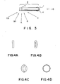
- Fig. 3 is a view of the catheter of Fig. 2, as seen from above;
- Figs. 4-A to 4-D are enlarged views of the X-ray fluoroscopic images of the radio opaque ring member, when viewed from the directions indicated by the arrows in Fig. 3;
- Fig. 5 is a view for explaining a state wherein the catheter distal end portion is parallel to the X-ray fluoroscopic plane, and a state wherein the distal end portion is twisted at angle ϑ;
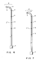
- Fig. 6 is a side view of a catheter according to another embodiment of the present invention;
- Fig. 7 is a side view of a catheter according to yet another embodiment of the present invention;
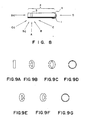
- Fig. 8 is a view of the catheter of Fig. 7, as seen from above; and
- Figs. 9-A to 9-G are enlarged views of X-ray fluoroscopic images of the radio opaque ring member, when viewed from the directions indicated by the arrows in Fig. 8.
- A catheter according to the present invention will be now described, with reference to an embodiment shown in Fig. 2.
- Catheter l according to this embodiment has curved or flexible
distal end portion 2. Ifdistal end portion 2 is flexible, it is able to bend in use. One radioopaque ring member 3 is circumferentially formed indistal end portion 2 so as to cross the axial direction of catheter l. Radioopaque ring member 3 satisfies condition L ≦ Dtan(π/8) where L is a length of radioopaque ring member 3 along the axial direction of catheter l and D is an inner diameter of radioopaque ring member 3. - Catheter l comprises a hollow tube, and
connector 4 is connected to the proximal end of catheter l. In this embodiment,distal end portion 2 is a J-shaped curved portion having a predetermined shape.Distal end portion 2 may have any shape according to various types of operations. In addition,distal end portion 2 may be flexible so as to bend in use. - Various materials can be used for catheter l. Examples of the catheter material are flexible polyamide, polyurethane, polyethylene, polyester, an ethylene-vinyl acetate copolymer, silicone rubber, and polyvinyl chloride.
Distal end portion 2 may be formed integrally with the remaining straight portion or may be formed separately from the remaining portion. In the latter case, separate molded members are integrally formed later. - An X-ray contrast medium is preferably mixed in the resin constituting catheter l. Examples of the X-ray contrast medium are a bismuth compound (e.g., bismuth oxide and bismuth subcarbonate), a barium compound (e.g., barium sulfate), a lead compound (e.g., lead oxide), and a tungsten compound (e.g., tungsten oxide).
- Radio
opaque ring member 3 is circumferentially formed indistal end portion 2 so as to cross the axial direction of catheter l. To cross the axial direction of catheter l is to form radioopaque ring member 3 at a given angle with respect to the axis of catheter l. However, radioopaque ring member 3 is preferably perpendicular to the axial direction of catheter l. In this case, the direction of the distal end of catheter l can be distinctly identified. The radio opaque ring member satisfies condition L ≦ Dtan(π/8) where L is the length of the radio opaque ring member along the axial direction of catheter l and D is the inner diameter of the radio opaque ring member. When catheter l hasdistal end portion 2 satisfying the above condition, twisting ofdistal end portion 2 can be easily known. - Satisfaction of the above condition achieves the object of the present invention, as will be described with reference to Fig. 3 to 5.
- Fig. 3 is a view of catheter l of Fig. 2 when viewed from the top. Fig. 4-A is an enlarged view of the X-ray fluoroscopic image of radio
opaque ring member 3 when viewed from a direction of arrow A; Fig. 4-B is an enlarged view of the X-ray fluoroscopic image ofring member 3 when viewed from a direction of arrow B or Ba; Fig. 4-C is an enlarged view of the X-ray fluoroscopic image ofring member 3 when viewed from a direction of arrow C or Ca; and Fig. 4-D is an enlarged view of the X-ray fluoroscopic image ofring member 3 when viewed from a direction of arrow D. When radioopaque ring member 3 is observed at a position perpendicular to the axis of catheter l,ring member 3 is linearly observed. When the radioopaque ring member 3 is observed at a position parallel to the axis of catheter l, the ring shape can be clearly observed. Fig. 5 is an enlarged view showing a state whereindistal end portion 2 of catheter l is parallel to X-rayfluoroscopic plane 5 and a state whereindistal end portion 2 is twisted at angle ϑ with respect toplane 5. An radio opaque ring member image for L onplane 5 is defined as La and an radio opaque ring member image for D onplane 5 is defined as Da. If Da is larger than La, the image on X-rayfluoroscopic plane 5 represents a ring-like shape anddistal end portion 2 is detected not to be parallel to the plane. - La, Da, L, D, and ϑ has the following relations: La = Lcos ϑ and Da = Dsinϑ. La = Da is established if Lcosϑ = Dsinϑ. Therefore,
L = Dtanϑ ...(l)
Various tests were made by the present inventors and it was found thatdistal end portion 2 could be guided to a location of interest if ϑ was less than π/8 (= 22.5 degrees). A substitution of ϑ ≦ π/8 into equation (l) yields the following condition:
L ≦ Dtan(π/8) ...(2)
More specifically, tan(π/8) = 0.4l4, therefore
L ≦ D x 0.4l4 - According to the catheter of the present invention, if
distal end portion 2 of catheter l is twisted at an angle of 22.5 degrees or more with respect to the X-ray fluoroscopic plane, the resultant fluoroscopic image of radioopaque ring member 3 represents twisting of thedistal end portion 2. - The relationship between inner diameter D and length L (along the axial direction of catheter l) of radio
opaque ring member 3 preferably satisfies L ≦ Dtan(π/l2). Since π/l2 is l5 degrees, even slight twisting can be visually discriminated. - More specifically, if the inner diameter of radio
opaque ring member 3 is about 3 mm, length L of radioopaque ring member 3 along the axial direction of catheter l is preferably l mm or less and more preferably 0.l to l mm. - A plurality of radio
opaque ring members 3 are preferably formed excluding the one formed indistal end portion 2, as shown in Fig. 2. In this case, if a distance between the adjacent radio opaque ring members is determined, a magnification of the X-ray fluoroscopic image can be known by this distance. - Furthermore, a plurality of radio
opaque ring members 3 may be formed indistal end portion 2. As shown in Fig. 6, two radio opaque ring members spaced apart from each other are formed indistal end portion 2. The reference numerals as in Fig. 2 denote the same parts in Fig. 6, and a detailed description thereof will be omitted. - Since radio
opaque ring member 3 has only the X-ray contrast medium function, it may be made of a metal or formed by metal deposition or printing of a paint or the like containing a contrast medium. Preferably, a material having a good X-ray contrast medium function is used. In particular, if catheter l is made of a material mixed with an X-ray contrast medium, the material for the radio opaque ring member must have better X-ray contrast medium function. For this reason, radioopaque ring member 3 is preferably made of stainless steel, gold, a titanium-nickel alloy or the like. - Radio
opaque ring member 3 is preferably fitted on the outer surface of catheter l so as to have substantially the same outer diameter as that of catheter l without forming a step therebetween. - In order to mount the radio opaque ring member in the manner described above, the radio opaque ring member can be embedded in the wall of catheter l. Alternatively, an annular groove is formed on the outer surface of catheter l, and an radio opaque ring member is fitted in the groove. Furthermore, in order to smoothen the outer surface, a plastic coating can be formed thereon. In a preferable method, a shape memory alloy is used as a material of the radio opaque ring member and is wound around the catheter l to memorize the circumferential shape thereof. Thereafter, the shape memory alloy is straightened and is fitted in an annular groove formed on the outer surface of catheter l. In this state, the memory shape alloy is heated or cooled to restore the memorized shape, thereby easily mounting the radio opaque ring member on catheter l. The annular groove need not be formed on the outer surface of catheter l. In this case, the memory shape alloy is heated and the corresponding portion of the catheter is also heated to embed the alloy in the wall of catheter l. Various types of shape memory alloys may be used, and a typical example is a titanium-nickel alloy.
- A catheter according to another embodiment of the present invention will be described with reference to Figs. 7 to 9.
- Catheter l according to this embodiment has curved or flexible
distal end portion 2. Ifdistal end portion 2 is flexible, it is bent in use. One radioopaque ring member 3 is circumferentially formed indistal end portion 2 so as to cross the axial direction of catheter l. Radioopaque ring member 3 satisfies condition L ≦ Dtan(π/8) where L is a length of radioopaque ring member 3 along the axial direction of catheter l and D is an inner diameter of radioopaque ring member 3. -
Portion 6 having no X-ray contrast medium function is formed in radioopaque ring member 3 and extends along the axial direction of catheter l at a portion substantially perpendicular to the surface formed by bendingdistal end portion 2. - In this catheter, other radio opaque ring member
portions excluding portion 6 are the same as those in the above embodiment. Therefore,only portion 6 will be described below. -
Portion 6 having no X-ray contrast medium function extends along the axial direction of catheter l in a narrow strip-like shape but need not be parallel to the axis of catheter l.Portion 6 may be inclined at a given angle with respect to the axis of catheter l. It is thus essential forportion 6 to cross the main body of radioopaque ring member 3. Preferably, the radio opaque ring member is perpendicular to the axial direction of catheter l and the portion having no X-ray contrast medium function is parallel to the axis of catheter l. - The portion having no X-ray contrast medium function may have any form. For example, this portion may be slit 6 formed in radio
opaque ring member 3 or a member having no X-ray contrast medium function and connecting both ends ofring member 3. - The width of
portion 6 having no X-ray contrast medium function is preferably l/24 to l/4, more preferably l/8 to l/4 the overall circumferential length of radioopaque ring member 3. Within this range, X-ray fluoroscopic images ofring member 3 are not adversely affected. Therefore, the portion having no X-ray contrast medium function can be clearly identified in the X-ray fluoroscopic images. - X-ray distal end portion images of the catheter having a portion with no X-ray contrast medium function will be described with reference to Figs. 8 and 9.
- Fig. 8 is a view of the catheter of Fig. 7 when viewed from the top thereof. Fig. 9-A shows an enlarged X-ray fluoroscopic image of
ring member 3 when viewed from a direction of arrow A; Fig. 9-B shows an enlarged X-ray fluoroscopic image thereof when viewed from a direction of arrow B; Fig. 9-E shows an enlarged X-ray fluoroscopic image thereof when viewed from a direction of arrow Ba; Fig. 9-C shows an enlarged X-ray fluoroscopic image thereof when viewed from a direction of arrow C; Fig. 9-F shows an enlarged X-ray fluoroscopic image thereof when viewed from a direction of arrow Ca; Fig. 9-D shows an enlarged X-ray fluoroscopic image thereof when viewed from a direction of arrow D; and Fig. 9-G shows an enlarged X-ray fluoroscopic image thereof when viewed from a direction of arrow Da. - As can be apparent from the above figures, when the radio opaque ring member is observed at a position perpendicular to the axis of catheter l, the ring member is linearly observed. However, when the viewing position is changed to that parallel to the axis of catheter l, the ring member can be clearly observed as a ring-like shape. At the same time, the position of the portion having no radio opaque ring member is changed depending on the viewing positions. Therefore, the doctor can visually observe that
distal end portion 2 of catheter l is deviated on the X-ray fluoroscopic plane side or the opposite side with respect to the axis of catheter l. - The catheter according to the present invention can be used as an angiographic catheter for the abdomen, brain, heart, coronary artery and the like, a cardiac minute volume measuring catheter, a monitoring catheter (e.g., a blood pressure measuring catheter used near a heart), and an obturator or vasodilator therapeutic catheter as well as a catheter as a ureteral catheter, a cholangiographic catheter, abdominal catheter, or a bronchographic catheter.
- The catheters of the present invention, e.g., the angiographic catheters shown in Figs. 2, 6, and 7 can be used in the same manner as in the conventional catheter. For example, the curved distal end portion is straightened by a guide wire inserted in the catheter and is inserted in a femoral artery. When the catheter passes by an aortic arch, the guide wire is removed. The distal end of the catheter is turned through l80 degrees in a valsalva cavity and is inserted in the right coronary artery port. At the same time, the doctor checks the position of the catheter while observing the corresponding X-ray fluoroscopic image. The catheter is thus indwelled in the correct position. In particular, according to the catheter of the present invention, even if the distal end portion of the catheter is slightly deviated from the X-ray fluoroscopic plane, such a deviation can be checked since the radio opaque ring member provides a ring-like image. The doctor turns the catheter located outside the femoral artery such that the X-ray fluoroscopic image of the radio opaque ring member becomes linear. The distal end portion is set parallel to the X-ray fluoroscopic plane and the distal end portion is inserted in the right coronary artery port. Thereafter, an X-ray contrast medium is injected from the rear end portion of the catheter, thereby performing angiography.
- The present invention will be described in detail by way of its examples.
- Judkins type right coronary artery angiographic catheter 7Fr (outer diameter: 2.3 mm) with a curved distal end portion having a length of 5 to l0 mm was prepared. In this catheter, stainless radio opaque ring members each having an inner diameter of 2.l3 mm, an outer diameter of 2.33 mm, and a width (i.e., the length along the axial direction of the catheter) of 0.88 mm were formed on the outer circumferential surface portions at l-, 2l-, 4l-, and 8l-mm positions away from the distal end.
- The resultant catheter was inserted into the femoral artery and the aortic arch. The catheter was then rotated through l80 degrees in the valsalva cavity, and the distal end portion of the catheter was inserted in the right coronary artery. In this operation, the positional relationship between the X-ray fluoroscopic plane and the distal end portion of the catheter could be appropriately identified by the X-ray fluoroscopic image of the radio opaque ring members. Therefore, the distal end of the catheter could be accurately inserted in the right coronary artery port. By measuring a distance between the radio opaque ring members in the straight portion of the catheter with reference to the X-ray fluoroscopic image, a magnification of the X-ray fluoroscopic image could be accurately measured, and hence the diameter of the blood vessel could be measured. By using a pigtail catheter prepared as in the catheter, the size of the left ventricle of the heart could be accurately measured.
- Sones type angiographic catheter 7Fr (outer diameter: 2.3 mm) was prepared. Radio opaque ring members made of a shape memory alloy (titanium-nickel alloy) were straightened and mounted on the outer surface of catheter at l-, 2l-, 4l-, and 8l-mm positions away from the distal end of the catheter. Each radio opaque ring member had a 0.5-mm wide slit, an inner diameter of 2.l3 mm, an outer diameter of 2.33 mm, and a width (length along the axial direction of the catheter) of 0.88 mm.
- Hot air was blown to the set portions to soften the catheter material, and at the same time the radio opaque ring members restored the memorized shape and were embedded in the wall of the catheter.
- The resultant catheter was inserted in the left coronary artery and the left ventricle of the heart under the fluoroscopic observation.
- The distal end portion of the catheter could be stereographically observed, and the forward or reverse rotational direction of the distal end portion could be identified according to the position of the slit, thus achieving easy indwelling.
- By measuring a distance between the radio opaque ring members of the linear catheter portion in the X-ray fluoroscopic image, the magnification of the X-ray fluoroscopic image could be accurately measured. As a result, the size of the left ventricle could be accurately measured.
- In the catheter having the curved distal end portion or the flexible distal end portion to be curved in use, at least one radio opaque ring member is mounted on the catheter so as to cross the axial direction of the catheter. In addition, inner diameter D and length L of the radio opaque ring member satisfy condition L ≦ Dtan(π/8). If the distal end portion of the catheter is twisted at an angle exceeding 22.5 degrees with respect to the X-ray fluoroscopic plane, the X-ray fluoroscopic image of the radio opaque ring member represents a ring-like shape, thereby allowing the operator to easily identify twisting of the distal end portion of the catheter and to easily correct such twisting. Therefore, the catheter can be easily indwelled in the location of interest.
- When the radio opaque ring member is arranged perpendicular to the axial direction of the catheter, the direction of the distal end of the catheter can be identified.
- In the catheter having the curved distal end portion or the flexible distal end portion to be curved in use, at least one radio opaque ring member is mounted on the outer surface of the distal end portion so as to cross the axial direction of the catheter. At the same time, inner diameter D and length L of the radio opaque ring member satisfy condition L ≦ Dtan(π/8). In addition, this radio opaque ring member has a portion having no X-ray contrast medium function and extending along the axial direction of the catheter. If the distal end portion of the catheter is twisted at an angle exceeding 22.5 degrees with respect to the X-ray fluoroscopic plane, the X-ray fluoroscopic image represents a ring-like image of the radio opaque ring member. In addition, the forward or reverse rotational direction of the distal end with respect to the axis of the catheter can be identified, and thus twisting of the distal end portion can be easily corrected. If the width of the portion having no X-ray contrast medium function falls within the range of l/24 to l/4 the overall circumferential length of the radio opaque ring member, the portion having no X-ray contrast medium function can be easily recognized in the X-ray fluoroscopic image thereof.
Claims (20)
L ≦ Dtan(π/8)
where D is the inner diameter of said radio opaque ring member and L is the length thereof along the axial direction of said catheter.
L ≦ Dtan(π/l2).
L ≦ Dtan(π/8)
where D is the inner diameter of said radio opaque ring member and L is the length thereof along the axial direction of said catheter, said radio opaque ring member being provided with a portion of no or less radio opaque and extending along the axial direction of said catheter.
L ≦ Dtan(π/l2).
Applications Claiming Priority (2)
| Application Number | Priority Date | Filing Date | Title |
|---|---|---|---|
| JP61105744A JPS62261371A (en) | 1986-05-08 | 1986-05-08 | Catheter |
| JP105744/86 | 1986-05-08 |
Publications (3)
| Publication Number | Publication Date |
|---|---|
| EP0244818A2 true EP0244818A2 (en) | 1987-11-11 |
| EP0244818A3 EP0244818A3 (en) | 1990-10-10 |
| EP0244818B1 EP0244818B1 (en) | 1994-07-20 |
Family
ID=14415768
Family Applications (1)
| Application Number | Title | Priority Date | Filing Date |
|---|---|---|---|
| EP87106484A Expired - Lifetime EP0244818B1 (en) | 1986-05-08 | 1987-05-05 | Catheter |
Country Status (5)
| Country | Link |
|---|---|
| US (1) | US4838879A (en) |
| EP (1) | EP0244818B1 (en) |
| JP (1) | JPS62261371A (en) |
| AU (1) | AU583459B2 (en) |
| DE (1) | DE3750239T2 (en) |
Cited By (10)
| Publication number | Priority date | Publication date | Assignee | Title |
|---|---|---|---|---|
| FR2630215A1 (en) * | 1988-04-13 | 1989-10-20 | Benhaim Jean | Measuring device and method for calculating radiological magnification in a single measurement |
| EP0408245A1 (en) * | 1989-07-13 | 1991-01-16 | American Medical Systems, Inc. | Stent placement instrument |
| EP0513836A1 (en) * | 1991-05-17 | 1992-11-19 | Act Medical, Inc. | Device having a radiopaque marker for endoscopic accessories and method of making same |
| WO1998022176A1 (en) * | 1996-11-18 | 1998-05-28 | Daig Corporation | Guiding introducer with openings containing ablation catheter |
| NL1007371C2 (en) * | 1997-10-27 | 1999-04-28 | Cordis Europ | Method for manufacturing a catheter with at least one marking |
| EP0963764A1 (en) * | 1997-03-31 | 1999-12-15 | Piolax Inc. | Self-retaining catheter and inserting device |
| WO2001030254A1 (en) * | 1999-10-26 | 2001-05-03 | Cedara Software Corp. | Catheter with radiopaque markers for 3d position tracking |
| FR2805750A1 (en) * | 2000-03-02 | 2001-09-07 | Braun Celsa Sa | External flexible bio-compatible sheath for a medical implant for humans and animals and fabrication method |
| WO2002002173A1 (en) * | 2000-06-30 | 2002-01-10 | Cedars Sinai Medical Center | Image guidance method coronary stent deployment |
| WO2009052818A1 (en) * | 2007-10-25 | 2009-04-30 | Franz Herbst | Marking for surgical instruments and implants |
Families Citing this family (125)
| Publication number | Priority date | Publication date | Assignee | Title |
|---|---|---|---|---|
| US4938741A (en) * | 1988-11-01 | 1990-07-03 | Ballard Medical Products | Medical ventilating and aspirating apparatus and methods |
| US5116309A (en) * | 1989-01-25 | 1992-05-26 | Coll Milton E | Ureteral stent-catheter system having varying diameter stent |
| US5221253A (en) * | 1989-01-25 | 1993-06-22 | Coll Milton E | Urological stent-catheter system having varing diameter stent |
| US5364340A (en) * | 1989-01-25 | 1994-11-15 | Coll Milton E | Ureteral stent-catheter having varying internal diameter and method of use |
| JPH0622583B2 (en) * | 1989-04-21 | 1994-03-30 | 株式会社潤工社 | Contrast tube |
| US5045072A (en) * | 1989-06-13 | 1991-09-03 | Cordis Corporation | Catheter having highly radiopaque, flexible tip |
| WO1991005577A1 (en) * | 1989-10-05 | 1991-05-02 | The Board Of Trustees Of The Leland Stanford Junior University | Catheter device with insertion stop means |
| US7033325B1 (en) | 1989-12-19 | 2006-04-25 | Scimed Life Systems, Inc. | Guidewire with multiple radiopaque marker sections |
| US5209730A (en) | 1989-12-19 | 1993-05-11 | Scimed Life Systems, Inc. | Method for placement of a balloon dilatation catheter across a stenosis and apparatus therefor |
| USRE41029E1 (en) | 1990-03-13 | 2009-12-01 | The Regents Of The University Of California | Endovascular electrolytically detachable wire and tip for the formation of thrombus in arteries, veins, aneurysms, vascular malformations and arteriovenous fistulas |
| USRE42625E1 (en) | 1990-03-13 | 2011-08-16 | The Regents Of The University Of California | Endovascular electrolytically detachable wire and tip for the formation of thrombus in arteries, veins, aneurysms, vascular malformations and arteriovenous fistulas |
| US6083220A (en) | 1990-03-13 | 2000-07-04 | The Regents Of The University Of California | Endovascular electrolytically detachable wire and tip for the formation of thrombus in arteries, veins, aneurysms, vascular malformations and arteriovenous fistulas |
| JP3001609B2 (en) * | 1990-05-09 | 2000-01-24 | 株式会社潤工社 | Tube with contrast agent |
| JP2830440B2 (en) * | 1990-09-21 | 1998-12-02 | 東洋紡績株式会社 | Cannula |
| US5078701A (en) * | 1990-10-05 | 1992-01-07 | Bissell Medical Products, Inc. | Wire guided intestinal catheter |
| US5259837A (en) * | 1990-12-27 | 1993-11-09 | Wormer Mark E Van | Acoustically enhanced catheter |
| US5188619A (en) * | 1991-04-24 | 1993-02-23 | Gene E. Myers Enterprises, Inc. | Internal thoractic artery catheter |
| EP0565648A4 (en) * | 1991-05-15 | 1994-07-06 | Bard Inc C R | Sizing balloon catheter |
| ES2090569T3 (en) * | 1991-06-03 | 1996-10-16 | Schneider Europ Ag | CATHETER SYSTEM FOR MECHANICAL DILATION OF CORONARY STENOSIS. |
| US5437290A (en) * | 1991-09-06 | 1995-08-01 | Board Of Trustees Of The Leland Stanford Jr. University | System and method for monitoring intraluminal device position |
| US5163927A (en) * | 1991-10-17 | 1992-11-17 | Imagyn Medical, Inc. | Linear eversion catheter system with position indicating indicia |
| JPH0548953U (en) * | 1991-12-05 | 1993-06-29 | アロカ株式会社 | Medical catheter |
| GB2263641A (en) * | 1992-01-30 | 1993-08-04 | Intravascular Res Ltd | Determining catheter location |
| US5669878A (en) * | 1992-01-30 | 1997-09-23 | Intravascular Research Limited | Guide wire for a catheter with position indicating means |
| US5215540A (en) * | 1992-01-31 | 1993-06-01 | St. Jude Medical, Inc. | Right coronary catheter |
| US5203777A (en) * | 1992-03-19 | 1993-04-20 | Lee Peter Y | Radiopaque marker system for a tubular device |
| US5396880A (en) * | 1992-04-08 | 1995-03-14 | Danek Medical, Inc. | Endoscope for direct visualization of the spine and epidural space |
| US5531721A (en) * | 1992-07-02 | 1996-07-02 | Scimed Life Systems, Inc. | Multiple member intravascular guide catheter |
| US5984909A (en) * | 1993-08-13 | 1999-11-16 | Daig Corporation | Coronary sinus catheter |
| US6001085A (en) * | 1993-08-13 | 1999-12-14 | Daig Corporation | Coronary sinus catheter |
| US5427115A (en) * | 1993-09-13 | 1995-06-27 | Boston Scientific Corporation | Apparatus for stricture diagnosis and treatment |
| US5342295A (en) * | 1993-09-24 | 1994-08-30 | Cardiac Pathways Corporation | Catheter assembly, catheter and multi-port introducer for use therewith |
| US5908446A (en) * | 1994-07-07 | 1999-06-01 | Cardiac Pathways Corporation | Catheter assembly, catheter and multi-port introducer for use therewith |
| US5607462A (en) * | 1993-09-24 | 1997-03-04 | Cardiac Pathways Corporation | Catheter assembly, catheter and multi-catheter introducer for use therewith |
| US5427119A (en) * | 1993-11-03 | 1995-06-27 | Daig Corporation | Guiding introducer for right atrium |
| US5497774A (en) * | 1993-11-03 | 1996-03-12 | Daig Corporation | Guiding introducer for left atrium |
| US5575766A (en) * | 1993-11-03 | 1996-11-19 | Daig Corporation | Process for the nonsurgical mapping and treatment of atrial arrhythmia using catheters guided by shaped guiding introducers |
| US5334167A (en) * | 1993-11-19 | 1994-08-02 | Cocanower David A | Modified nasogastric tube for use in enteral feeding |
| US5911715A (en) * | 1994-02-14 | 1999-06-15 | Scimed Life Systems, Inc. | Guide catheter having selected flexural modulus segments |
| US5569218A (en) * | 1994-02-14 | 1996-10-29 | Scimed Life Systems, Inc. | Elastic guide catheter transition element |
| US6858024B1 (en) | 1994-02-14 | 2005-02-22 | Scimed Life Systems, Inc. | Guide catheter having selected flexural modulus segments |
| US5411016A (en) * | 1994-02-22 | 1995-05-02 | Scimed Life Systems, Inc. | Intravascular balloon catheter for use in combination with an angioscope |
| US5694922A (en) | 1994-05-18 | 1997-12-09 | Ballard Medical Products | Swivel tube connections with hermetic seals |
| US6494203B1 (en) | 1994-08-19 | 2002-12-17 | Ballard Medical Products | Medical aspirating/ventilating closed system improvements and methods |
| US5514108A (en) * | 1994-09-01 | 1996-05-07 | Cordis Corporation | Soft flexible catheter tip for use in angiography |
| US5599319A (en) * | 1994-09-01 | 1997-02-04 | Cordis Corporation | Soft flexible catheter tip for use in angiography |
| US5558652A (en) * | 1994-10-06 | 1996-09-24 | B. Braun Medical, Inc. | Introducer with radiopaque marked tip and method of manufacture therefor |
| US5814029A (en) * | 1994-11-03 | 1998-09-29 | Daig Corporation | Guiding introducer system for use in ablation and mapping procedures in the left ventricle |
| US5771895A (en) * | 1996-02-12 | 1998-06-30 | Slager; Cornelis J. | Catheter for obtaining three-dimensional reconstruction of a vascular lumen and wall |
| US5690620A (en) * | 1996-05-14 | 1997-11-25 | Knott; Michael Mcfarland | Anatomically conforming nasogastric tube with normally-curved tip and method for using same |
| US5846229A (en) * | 1996-05-31 | 1998-12-08 | Scimed Life Systems, Inc. | Catheter for the right coronary artery |
| US5899890A (en) * | 1996-06-21 | 1999-05-04 | Medtronic, Inc. | Flow-directed catheter system and method of use |
| US5830145A (en) * | 1996-09-20 | 1998-11-03 | Cardiovascular Imaging Systems, Inc. | Enhanced accuracy of three-dimensional intraluminal ultrasound (ILUS) image reconstruction |
| US5895378A (en) * | 1997-05-29 | 1999-04-20 | Target Therapeutics, Inc. | Flow-directed catheter having multiple tapers and radio-opaque markers |
| US5938660A (en) * | 1997-06-27 | 1999-08-17 | Daig Corporation | Process and device for the treatment of atrial arrhythmia |
| US6251109B1 (en) * | 1997-06-27 | 2001-06-26 | Daig Corporation | Process and device for the treatment of atrial arrhythmia |
| US5908413A (en) * | 1997-10-03 | 1999-06-01 | Scimed Life Systems, Inc. | Radiopaque catheter and method of manufacture thereof |
| US6077258A (en) * | 1997-10-03 | 2000-06-20 | Scimed Life Systems, Inc. | Braided angiography catheter having full length radiopacity and controlled flexibility |
| US6074407A (en) * | 1997-10-14 | 2000-06-13 | Target Therapeutics, Inc. | Delivery catheter for occlusive implants |
| US6036682A (en) * | 1997-12-02 | 2000-03-14 | Scimed Life Systems, Inc. | Catheter having a plurality of integral radiopaque bands |
| US6200315B1 (en) | 1997-12-18 | 2001-03-13 | Medtronic, Inc. | Left atrium ablation catheter |
| US6285903B1 (en) | 1998-06-30 | 2001-09-04 | Eclipse Surgical Technologies, Inc. | Intracorporeal device with radiopaque marker |
| US6464684B1 (en) | 1998-09-09 | 2002-10-15 | Scimed Life Systems, Inc. | Catheter having regions of differing braid densities and methods of manufacture therefor |
| EP0987042A3 (en) * | 1998-09-15 | 2000-11-02 | Medtronic, Inc. | Design and method to fabricate PTCA balloon radiopaque marker band |
| US7314477B1 (en) | 1998-09-25 | 2008-01-01 | C.R. Bard Inc. | Removable embolus blood clot filter and filter delivery unit |
| US6709429B1 (en) | 2000-01-19 | 2004-03-23 | Scimed Life Systems, Inc. | Intravascular catheter with multiple axial fibers |
| US6942654B1 (en) | 2000-01-19 | 2005-09-13 | Scimed Life Systems, Inc. | Intravascular catheter with axial member |
| US6171295B1 (en) | 1999-01-20 | 2001-01-09 | Scimed Life Systems, Inc. | Intravascular catheter with composite reinforcement |
| US6497698B1 (en) * | 1999-05-20 | 2002-12-24 | Cardiac Assist, Inc. | Method and apparatus for treating a patient |
| US6500285B2 (en) | 1999-08-23 | 2002-12-31 | Scimed Life Systems, Inc. | Method of making a catheter having interlocking ribbed bond regions |
| JP3754263B2 (en) * | 2000-02-28 | 2006-03-08 | 日本ライフライン株式会社 | Spiral wire, medical insertion line, and method for manufacturing spiral wire |
| JP2003033437A (en) * | 2001-07-23 | 2003-02-04 | Suugan Kk | Catheter |
| US7018346B2 (en) * | 2001-12-18 | 2006-03-28 | Scimed Life Systems, Inc. | Guide wire with adjustable flexibility |
| US6945970B2 (en) * | 2001-12-27 | 2005-09-20 | Scimed Life Systems, Inc. | Catheter incorporating a curable polymer layer to control flexibility and method of manufacture |
| IL154391A (en) * | 2002-02-11 | 2009-05-04 | Given Imaging Ltd | Self propelled device |
| US9204956B2 (en) | 2002-02-20 | 2015-12-08 | C. R. Bard, Inc. | IVC filter with translating hooks |
| US6733489B2 (en) * | 2002-09-26 | 2004-05-11 | Angiodynamics, Inc. | Vascular orientation marker for determining the orientation of a blood vessel |
| US20040068190A1 (en) * | 2002-10-04 | 2004-04-08 | Cespedes Eduardo Ignacio | Imaging catheter with indicia and methods of use |
| US20040181186A1 (en) * | 2003-03-13 | 2004-09-16 | Scimed Life Systems, Inc. | Medical device |
| US7789877B2 (en) * | 2003-07-02 | 2010-09-07 | St. Jude Medical, Atrial Fibrillation Division, Inc. | Ablation catheter electrode arrangement |
| US7824392B2 (en) | 2003-08-20 | 2010-11-02 | Boston Scientific Scimed, Inc. | Catheter with thin-walled braid |
| US7615043B2 (en) * | 2003-08-20 | 2009-11-10 | Boston Scientific Scimed, Inc. | Medical device incorporating a polymer blend |
| US7229437B2 (en) * | 2003-09-22 | 2007-06-12 | St. Jude Medical, Atrial Fibrillation Division, Inc. | Medical device having integral traces and formed electrodes |
| US7234225B2 (en) * | 2003-09-22 | 2007-06-26 | St. Jude Medical, Atrial Fibrillation Division, Inc. | Method for manufacturing medical device having embedded traces and formed electrodes |
| US8147486B2 (en) * | 2003-09-22 | 2012-04-03 | St. Jude Medical, Atrial Fibrillation Division, Inc. | Medical device with flexible printed circuit |
| US20050149176A1 (en) * | 2003-12-29 | 2005-07-07 | Scimed Life Systems, Inc. | Selectively light curable support members for medical devices |
| US7704267B2 (en) | 2004-08-04 | 2010-04-27 | C. R. Bard, Inc. | Non-entangling vena cava filter |
| US7794473B2 (en) | 2004-11-12 | 2010-09-14 | C.R. Bard, Inc. | Filter delivery system |
| US20060111649A1 (en) * | 2004-11-19 | 2006-05-25 | Scimed Life Systems, Inc. | Catheter having improved torque response and curve retention |
| US7828790B2 (en) | 2004-12-03 | 2010-11-09 | Boston Scientific Scimed, Inc. | Selectively flexible catheter and method of use |
| EP1835855B1 (en) | 2005-01-11 | 2017-04-05 | Volcano Corporation | Vascular image co-registration |
| US8267954B2 (en) | 2005-02-04 | 2012-09-18 | C. R. Bard, Inc. | Vascular filter with sensing capability |
| US8702744B2 (en) * | 2005-05-09 | 2014-04-22 | Nexeon Medsystems, Inc. | Apparatus and methods for renal stenting |
| MX2007013932A (en) | 2005-05-12 | 2008-01-28 | Bard Inc C R | Removable embolus blood clot filter. |
| US20060255510A1 (en) * | 2005-05-13 | 2006-11-16 | Spx Corporation | X-ray detection of polymer components in material processing |
| US20060255511A1 (en) * | 2005-05-13 | 2006-11-16 | Hardy Benjamin G | X-ray detection of the presence and/or condition of polymer components |
| JP4771456B2 (en) | 2005-05-13 | 2011-09-14 | テルモ株式会社 | catheter |
| EP1903944B1 (en) | 2005-06-24 | 2017-04-19 | Volcano Corporation | Co-registration of graphical image data representing three-dimensional vascular features |
| US8062327B2 (en) | 2005-08-09 | 2011-11-22 | C. R. Bard, Inc. | Embolus blood clot filter and delivery system |
| US9131999B2 (en) * | 2005-11-18 | 2015-09-15 | C.R. Bard Inc. | Vena cava filter with filament |
| US20100256669A1 (en) * | 2005-12-02 | 2010-10-07 | C.R. Bard, Inc. | Helical Vena Cava Filter |
| WO2007133366A2 (en) * | 2006-05-02 | 2007-11-22 | C. R. Bard, Inc. | Vena cava filter formed from a sheet |
| CA2655158A1 (en) * | 2006-06-05 | 2007-12-13 | C.R. Bard Inc. | Embolus blood clot filter utilizable with a single delivery system or a single retrieval system in one of a femoral or jugular access |
| US20080125752A1 (en) * | 2006-08-09 | 2008-05-29 | Boston Scientific Scimed, Inc. | Catheter assembly having a modified reinforcement layer |
| US20080058764A1 (en) * | 2006-08-29 | 2008-03-06 | Majercak David C | Catheter Tip Configuration for Improved Crossability and Trackability |
| JP5446518B2 (en) * | 2009-07-01 | 2014-03-19 | 住友ベークライト株式会社 | catheter |
| AU2010278893B2 (en) | 2009-07-29 | 2014-02-27 | C.R. Bard, Inc. | Tubular filter |
| US8731642B2 (en) * | 2009-11-08 | 2014-05-20 | Paieon Inc. | Apparatus and method for locating a device tip within a volume |
| IT1402568B1 (en) * | 2010-11-10 | 2013-09-13 | Flag Vascular Srl | ANGIOGRAPHIC CATHETER FOR THE MEASUREMENT OF THE TRANSMISSION SPEED OF THE AORTIC PRESSORY WAVE |
| US8849375B2 (en) * | 2011-11-01 | 2014-09-30 | Siemens Medical Solutions Usa, Inc. | System for detecting rotation angle of a catheter in an X-ray image |
| US9233015B2 (en) | 2012-06-15 | 2016-01-12 | Trivascular, Inc. | Endovascular delivery system with an improved radiopaque marker scheme |
| US10004467B2 (en) * | 2014-04-25 | 2018-06-26 | Medtronic, Inc. | Guidance system for localization and cannulation of the coronary sinus |
| US20170095606A1 (en) * | 2014-06-26 | 2017-04-06 | Samsung Life Public Welfare Foundation | Integrated Double Cannula for ECMO |
| JP1677498S (en) | 2020-04-01 | 2021-01-25 | ||
| JP1680403S (en) | 2020-04-01 | 2021-03-08 | ||
| JP1680404S (en) | 2020-04-01 | 2021-03-08 | ||
| JP1677499S (en) | 2020-04-01 | 2021-01-25 | ||
| JP1694630S (en) | 2020-05-14 | 2021-09-13 | ||
| USD958350S1 (en) | 2020-05-14 | 2022-07-19 | Terumo Kabushiki Kaisha | Catheter |
| JP1670410S (en) | 2020-05-14 | 2020-10-19 | ||
| JP1701146S (en) | 2020-05-14 | 2021-11-29 | ||
| WO2022079771A1 (en) * | 2020-10-12 | 2022-04-21 | 朝日インテック株式会社 | Medical device |
| JP2023552437A (en) * | 2020-12-07 | 2023-12-15 | エムブイアールエックス, インコーポレイテッド | Devices, methods, and systems for reshaping heart valve annulus |
| USD980976S1 (en) * | 2021-04-30 | 2023-03-14 | New York Society For The Relief Of The Ruptured And Crippled, Maintaining The Hospital For Special Surgery | Surgical cannula guide |
| JP7403617B1 (en) * | 2022-12-09 | 2023-12-22 | 日本ライフライン株式会社 | catheter |
Citations (3)
| Publication number | Priority date | Publication date | Assignee | Title |
|---|---|---|---|---|
| US3995617A (en) * | 1972-05-31 | 1976-12-07 | Watkins David H | Heart assist method and catheter |
| US4279252A (en) * | 1979-08-24 | 1981-07-21 | Martin Michael T | X-ray scaling catheter |
| US4586923A (en) * | 1984-06-25 | 1986-05-06 | Cordis Corporation | Curving tip catheter |
Family Cites Families (13)
| Publication number | Priority date | Publication date | Assignee | Title |
|---|---|---|---|---|
| US2212334A (en) * | 1936-08-15 | 1940-08-20 | Mueller & Co V | Catheter |
| US3483859A (en) * | 1967-11-29 | 1969-12-16 | Fred E Pittman | String for marking bleeding in upper gastro-intestinal tract |
| US3605750A (en) * | 1969-04-07 | 1971-09-20 | David S Sheridan | X-ray tip catheter |
| US3885561A (en) * | 1971-12-15 | 1975-05-27 | Charles N Mazal Cami | Catheter |
| GB1511269A (en) * | 1974-12-20 | 1978-05-17 | Sherwood Medical Ind Inc | Method of making a catheter with x-ray opaque markings |
| DE2927788A1 (en) * | 1978-08-04 | 1980-02-21 | Wallace Ltd H G | IMPROVEMENTS ON INTRAVASCULAR CATHETERS |
| EP0033659A3 (en) * | 1980-02-04 | 1982-02-17 | Teleflex Incorporated | Medical-surgical catheter |
| US4657024A (en) * | 1980-02-04 | 1987-04-14 | Teleflex Incorporated | Medical-surgical catheter |
| US4469483A (en) * | 1982-08-25 | 1984-09-04 | Baxter Travenol Laboratories, Inc. | Radiopaque catheter |
| US4774949A (en) * | 1983-06-14 | 1988-10-04 | Fogarty Thomas J | Deflector guiding catheter |
| US4571240A (en) * | 1983-08-12 | 1986-02-18 | Advanced Cardiovascular Systems, Inc. | Catheter having encapsulated tip marker |
| US4581390A (en) * | 1984-06-29 | 1986-04-08 | Flynn Vincent J | Catheters comprising radiopaque polyurethane-silicone network resin compositions |
| US4671291A (en) * | 1986-03-31 | 1987-06-09 | Siemens Medical Systems, Inc. | Angle encoding catheter |
-
1986
- 1986-05-08 JP JP61105744A patent/JPS62261371A/en active Granted
-
1987
- 1987-05-01 US US07/045,601 patent/US4838879A/en not_active Expired - Fee Related
- 1987-05-05 DE DE3750239T patent/DE3750239T2/en not_active Expired - Fee Related
- 1987-05-05 EP EP87106484A patent/EP0244818B1/en not_active Expired - Lifetime
- 1987-05-07 AU AU72670/87A patent/AU583459B2/en not_active Ceased
Patent Citations (3)
| Publication number | Priority date | Publication date | Assignee | Title |
|---|---|---|---|---|
| US3995617A (en) * | 1972-05-31 | 1976-12-07 | Watkins David H | Heart assist method and catheter |
| US4279252A (en) * | 1979-08-24 | 1981-07-21 | Martin Michael T | X-ray scaling catheter |
| US4586923A (en) * | 1984-06-25 | 1986-05-06 | Cordis Corporation | Curving tip catheter |
Cited By (11)
| Publication number | Priority date | Publication date | Assignee | Title |
|---|---|---|---|---|
| FR2630215A1 (en) * | 1988-04-13 | 1989-10-20 | Benhaim Jean | Measuring device and method for calculating radiological magnification in a single measurement |
| EP0408245A1 (en) * | 1989-07-13 | 1991-01-16 | American Medical Systems, Inc. | Stent placement instrument |
| EP0513836A1 (en) * | 1991-05-17 | 1992-11-19 | Act Medical, Inc. | Device having a radiopaque marker for endoscopic accessories and method of making same |
| WO1998022176A1 (en) * | 1996-11-18 | 1998-05-28 | Daig Corporation | Guiding introducer with openings containing ablation catheter |
| EP0963764A1 (en) * | 1997-03-31 | 1999-12-15 | Piolax Inc. | Self-retaining catheter and inserting device |
| US6074378A (en) * | 1997-03-31 | 2000-06-13 | Piolax Inc. | Self-retaining catheter and inserting apparatus thereof |
| NL1007371C2 (en) * | 1997-10-27 | 1999-04-28 | Cordis Europ | Method for manufacturing a catheter with at least one marking |
| WO2001030254A1 (en) * | 1999-10-26 | 2001-05-03 | Cedara Software Corp. | Catheter with radiopaque markers for 3d position tracking |
| FR2805750A1 (en) * | 2000-03-02 | 2001-09-07 | Braun Celsa Sa | External flexible bio-compatible sheath for a medical implant for humans and animals and fabrication method |
| WO2002002173A1 (en) * | 2000-06-30 | 2002-01-10 | Cedars Sinai Medical Center | Image guidance method coronary stent deployment |
| WO2009052818A1 (en) * | 2007-10-25 | 2009-04-30 | Franz Herbst | Marking for surgical instruments and implants |
Also Published As
| Publication number | Publication date |
|---|---|
| JPH0331063B2 (en) | 1991-05-02 |
| JPS62261371A (en) | 1987-11-13 |
| AU7267087A (en) | 1987-12-17 |
| DE3750239D1 (en) | 1994-08-25 |
| DE3750239T2 (en) | 1994-12-15 |
| AU583459B2 (en) | 1987-12-17 |
| EP0244818A3 (en) | 1990-10-10 |
| US4838879A (en) | 1989-06-13 |
| EP0244818B1 (en) | 1994-07-20 |
Similar Documents
| Publication | Publication Date | Title |
|---|---|---|
| EP0244818B1 (en) | Catheter | |
| US11744988B2 (en) | Variable flexibility catheter support frame | |
| US6039699A (en) | Stiff catheter guidewire with flexible distal portion | |
| EP0759793B1 (en) | Catheter guide wire with multiple radiopacity | |
| US5558652A (en) | Introducer with radiopaque marked tip and method of manufacture therefor | |
| EP1652548B1 (en) | Medical guide wire | |
| JP6086984B2 (en) | Pressure sensing guide wire | |
| JP2022185129A (en) | Module type blood vessel catheter | |
| JP6412505B2 (en) | Steerable guidewire and method of use | |
| US20090254000A1 (en) | Micromachined composite guidewire structure with anisotropic bending properties | |
| EP0608853A2 (en) | Vascular dilatation instrument and catheter | |
| CN110072588B (en) | Guide extension catheter | |
| CN112672780B (en) | Catheter support frame with variable flexibility | |
| CN213724309U (en) | Interventional guide wire and intubation tube capable of ultrasonic development | |
| US7048695B1 (en) | Guiding aid | |
| KR102569983B1 (en) | Biopsy needle for accessing peripheral lung nodules | |
| US20220016396A1 (en) | Catheter With Embedded Core Wires And Shaping Ribbons | |
| JP3724652B2 (en) | Anchor guide wire | |
| US11324931B2 (en) | Autonomous guidewire | |
| CN214286246U (en) | Adjustable bent sheath | |
| US20180064913A1 (en) | Guidewire | |
| WO2024024349A1 (en) | Dilator | |
| JP2005329018A (en) | Medical appliance | |
| JPH0631749U (en) | Guide wire |
Legal Events
| Date | Code | Title | Description |
|---|---|---|---|
| PUAI | Public reference made under article 153(3) epc to a published international application that has entered the european phase |
Free format text: ORIGINAL CODE: 0009012 |
|
| 17P | Request for examination filed |
Effective date: 19870602 |
|
| AK | Designated contracting states |
Kind code of ref document: A2 Designated state(s): BE DE FR GB IT SE |
|
| PUAL | Search report despatched |
Free format text: ORIGINAL CODE: 0009013 |
|
| AK | Designated contracting states |
Kind code of ref document: A3 Designated state(s): BE DE FR GB IT SE |
|
| 17Q | First examination report despatched |
Effective date: 19921110 |
|
| RBV | Designated contracting states (corrected) |
Designated state(s): DE FR IT |
|
| GRAA | (expected) grant |
Free format text: ORIGINAL CODE: 0009210 |
|
| AK | Designated contracting states |
Kind code of ref document: B1 Designated state(s): DE FR IT |
|
| ET | Fr: translation filed | ||
| REF | Corresponds to: |
Ref document number: 3750239 Country of ref document: DE Date of ref document: 19940825 |
|
| ITF | It: translation for a ep patent filed |
Owner name: FUMERO BREVETTI S.N.C. |
|
| PGFP | Annual fee paid to national office [announced via postgrant information from national office to epo] |
Ref country code: FR Payment date: 19950510 Year of fee payment: 9 |
|
| PGFP | Annual fee paid to national office [announced via postgrant information from national office to epo] |
Ref country code: DE Payment date: 19950511 Year of fee payment: 9 |
|
| PLBE | No opposition filed within time limit |
Free format text: ORIGINAL CODE: 0009261 |
|
| STAA | Information on the status of an ep patent application or granted ep patent |
Free format text: STATUS: NO OPPOSITION FILED WITHIN TIME LIMIT |
|
| 26N | No opposition filed | ||
| PG25 | Lapsed in a contracting state [announced via postgrant information from national office to epo] |
Ref country code: FR Effective date: 19970131 |
|
| PG25 | Lapsed in a contracting state [announced via postgrant information from national office to epo] |
Ref country code: DE Effective date: 19970201 |
|
| REG | Reference to a national code |
Ref country code: FR Ref legal event code: ST |
|
| PG25 | Lapsed in a contracting state [announced via postgrant information from national office to epo] |
Ref country code: IT Free format text: LAPSE BECAUSE OF NON-PAYMENT OF DUE FEES;WARNING: LAPSES OF ITALIAN PATENTS WITH EFFECTIVE DATE BEFORE 2007 MAY HAVE OCCURRED AT ANY TIME BEFORE 2007. THE CORRECT EFFECTIVE DATE MAY BE DIFFERENT FROM THE ONE RECORDED. Effective date: 20050505 |