EP0243574A2 - Heat exchanger and method of producing heat exchangers - Google Patents
Heat exchanger and method of producing heat exchangers Download PDFInfo
- Publication number
- EP0243574A2 EP0243574A2 EP87100393A EP87100393A EP0243574A2 EP 0243574 A2 EP0243574 A2 EP 0243574A2 EP 87100393 A EP87100393 A EP 87100393A EP 87100393 A EP87100393 A EP 87100393A EP 0243574 A2 EP0243574 A2 EP 0243574A2
- Authority
- EP
- European Patent Office
- Prior art keywords
- sleeve
- tube
- heat exchanger
- tubes
- heat
- Prior art date
- Legal status (The legal status is an assumption and is not a legal conclusion. Google has not performed a legal analysis and makes no representation as to the accuracy of the status listed.)
- Granted
Links
Images

Classifications
-
- B—PERFORMING OPERATIONS; TRANSPORTING
- B29—WORKING OF PLASTICS; WORKING OF SUBSTANCES IN A PLASTIC STATE IN GENERAL
- B29C—SHAPING OR JOINING OF PLASTICS; SHAPING OF MATERIAL IN A PLASTIC STATE, NOT OTHERWISE PROVIDED FOR; AFTER-TREATMENT OF THE SHAPED PRODUCTS, e.g. REPAIRING
- B29C65/00—Joining or sealing of preformed parts, e.g. welding of plastics materials; Apparatus therefor
- B29C65/02—Joining or sealing of preformed parts, e.g. welding of plastics materials; Apparatus therefor by heating, with or without pressure
- B29C65/14—Joining or sealing of preformed parts, e.g. welding of plastics materials; Apparatus therefor by heating, with or without pressure using wave energy, i.e. electromagnetic radiation, or particle radiation
- B29C65/1429—Joining or sealing of preformed parts, e.g. welding of plastics materials; Apparatus therefor by heating, with or without pressure using wave energy, i.e. electromagnetic radiation, or particle radiation characterised by the way of heating the interface
- B29C65/1448—Joining or sealing of preformed parts, e.g. welding of plastics materials; Apparatus therefor by heating, with or without pressure using wave energy, i.e. electromagnetic radiation, or particle radiation characterised by the way of heating the interface radiating the edges of the parts to be joined, e.g. for curing a layer of adhesive placed between two flat parts to be joined, e.g. for making CDs or DVDs
-
- B—PERFORMING OPERATIONS; TRANSPORTING
- B29—WORKING OF PLASTICS; WORKING OF SUBSTANCES IN A PLASTIC STATE IN GENERAL
- B29C—SHAPING OR JOINING OF PLASTICS; SHAPING OF MATERIAL IN A PLASTIC STATE, NOT OTHERWISE PROVIDED FOR; AFTER-TREATMENT OF THE SHAPED PRODUCTS, e.g. REPAIRING
- B29C66/00—General aspects of processes or apparatus for joining preformed parts
- B29C66/01—General aspects dealing with the joint area or with the area to be joined
- B29C66/05—Particular design of joint configurations
- B29C66/10—Particular design of joint configurations particular design of the joint cross-sections
- B29C66/13—Single flanged joints; Fin-type joints; Single hem joints; Edge joints; Interpenetrating fingered joints; Other specific particular designs of joint cross-sections not provided for in groups B29C66/11 - B29C66/12
- B29C66/137—Beaded-edge joints or bead seals
-
- B—PERFORMING OPERATIONS; TRANSPORTING
- B29—WORKING OF PLASTICS; WORKING OF SUBSTANCES IN A PLASTIC STATE IN GENERAL
- B29C—SHAPING OR JOINING OF PLASTICS; SHAPING OF MATERIAL IN A PLASTIC STATE, NOT OTHERWISE PROVIDED FOR; AFTER-TREATMENT OF THE SHAPED PRODUCTS, e.g. REPAIRING
- B29C66/00—General aspects of processes or apparatus for joining preformed parts
- B29C66/50—General aspects of joining tubular articles; General aspects of joining long products, i.e. bars or profiled elements; General aspects of joining single elements to tubular articles, hollow articles or bars; General aspects of joining several hollow-preforms to form hollow or tubular articles
- B29C66/51—Joining tubular articles, profiled elements or bars; Joining single elements to tubular articles, hollow articles or bars; Joining several hollow-preforms to form hollow or tubular articles
- B29C66/52—Joining tubular articles, bars or profiled elements
- B29C66/522—Joining tubular articles
- B29C66/5227—Joining tubular articles for forming multi-tubular articles by longitudinally joining elementary tubular articles wall-to-wall (e.g. joining the wall of a first tubular article to the wall of a second tubular article) or for forming multilayer tubular articles
-
- B—PERFORMING OPERATIONS; TRANSPORTING
- B29—WORKING OF PLASTICS; WORKING OF SUBSTANCES IN A PLASTIC STATE IN GENERAL
- B29C—SHAPING OR JOINING OF PLASTICS; SHAPING OF MATERIAL IN A PLASTIC STATE, NOT OTHERWISE PROVIDED FOR; AFTER-TREATMENT OF THE SHAPED PRODUCTS, e.g. REPAIRING
- B29C66/00—General aspects of processes or apparatus for joining preformed parts
- B29C66/50—General aspects of joining tubular articles; General aspects of joining long products, i.e. bars or profiled elements; General aspects of joining single elements to tubular articles, hollow articles or bars; General aspects of joining several hollow-preforms to form hollow or tubular articles
- B29C66/51—Joining tubular articles, profiled elements or bars; Joining single elements to tubular articles, hollow articles or bars; Joining several hollow-preforms to form hollow or tubular articles
- B29C66/53—Joining single elements to tubular articles, hollow articles or bars
- B29C66/534—Joining single elements to open ends of tubular or hollow articles or to the ends of bars
- B29C66/5344—Joining single elements to open ends of tubular or hollow articles or to the ends of bars said single elements being substantially annular, i.e. of finite length, e.g. joining flanges to tube ends
-
- B—PERFORMING OPERATIONS; TRANSPORTING
- B29—WORKING OF PLASTICS; WORKING OF SUBSTANCES IN A PLASTIC STATE IN GENERAL
- B29C—SHAPING OR JOINING OF PLASTICS; SHAPING OF MATERIAL IN A PLASTIC STATE, NOT OTHERWISE PROVIDED FOR; AFTER-TREATMENT OF THE SHAPED PRODUCTS, e.g. REPAIRING
- B29C66/00—General aspects of processes or apparatus for joining preformed parts
- B29C66/50—General aspects of joining tubular articles; General aspects of joining long products, i.e. bars or profiled elements; General aspects of joining single elements to tubular articles, hollow articles or bars; General aspects of joining several hollow-preforms to form hollow or tubular articles
- B29C66/51—Joining tubular articles, profiled elements or bars; Joining single elements to tubular articles, hollow articles or bars; Joining several hollow-preforms to form hollow or tubular articles
- B29C66/53—Joining single elements to tubular articles, hollow articles or bars
- B29C66/534—Joining single elements to open ends of tubular or hollow articles or to the ends of bars
- B29C66/5346—Joining single elements to open ends of tubular or hollow articles or to the ends of bars said single elements being substantially flat
- B29C66/53465—Joining single elements to open ends of tubular or hollow articles or to the ends of bars said single elements being substantially flat said single flat elements being provided with holes facing the tube ends, e.g. for making heat-exchangers
-
- B—PERFORMING OPERATIONS; TRANSPORTING
- B29—WORKING OF PLASTICS; WORKING OF SUBSTANCES IN A PLASTIC STATE IN GENERAL
- B29C—SHAPING OR JOINING OF PLASTICS; SHAPING OF MATERIAL IN A PLASTIC STATE, NOT OTHERWISE PROVIDED FOR; AFTER-TREATMENT OF THE SHAPED PRODUCTS, e.g. REPAIRING
- B29C66/00—General aspects of processes or apparatus for joining preformed parts
- B29C66/70—General aspects of processes or apparatus for joining preformed parts characterised by the composition, physical properties or the structure of the material of the parts to be joined; Joining with non-plastics material
- B29C66/73—General aspects of processes or apparatus for joining preformed parts characterised by the composition, physical properties or the structure of the material of the parts to be joined; Joining with non-plastics material characterised by the intensive physical properties of the material of the parts to be joined, by the optical properties of the material of the parts to be joined, by the extensive physical properties of the parts to be joined, by the state of the material of the parts to be joined or by the material of the parts to be joined being a thermoplastic or a thermoset
- B29C66/739—General aspects of processes or apparatus for joining preformed parts characterised by the composition, physical properties or the structure of the material of the parts to be joined; Joining with non-plastics material characterised by the intensive physical properties of the material of the parts to be joined, by the optical properties of the material of the parts to be joined, by the extensive physical properties of the parts to be joined, by the state of the material of the parts to be joined or by the material of the parts to be joined being a thermoplastic or a thermoset characterised by the material of the parts to be joined being a thermoplastic or a thermoset
- B29C66/7392—General aspects of processes or apparatus for joining preformed parts characterised by the composition, physical properties or the structure of the material of the parts to be joined; Joining with non-plastics material characterised by the intensive physical properties of the material of the parts to be joined, by the optical properties of the material of the parts to be joined, by the extensive physical properties of the parts to be joined, by the state of the material of the parts to be joined or by the material of the parts to be joined being a thermoplastic or a thermoset characterised by the material of the parts to be joined being a thermoplastic or a thermoset characterised by the material of at least one of the parts being a thermoplastic
- B29C66/73921—General aspects of processes or apparatus for joining preformed parts characterised by the composition, physical properties or the structure of the material of the parts to be joined; Joining with non-plastics material characterised by the intensive physical properties of the material of the parts to be joined, by the optical properties of the material of the parts to be joined, by the extensive physical properties of the parts to be joined, by the state of the material of the parts to be joined or by the material of the parts to be joined being a thermoplastic or a thermoset characterised by the material of the parts to be joined being a thermoplastic or a thermoset characterised by the material of at least one of the parts being a thermoplastic characterised by the materials of both parts being thermoplastics
-
- F—MECHANICAL ENGINEERING; LIGHTING; HEATING; WEAPONS; BLASTING
- F28—HEAT EXCHANGE IN GENERAL
- F28F—DETAILS OF HEAT-EXCHANGE AND HEAT-TRANSFER APPARATUS, OF GENERAL APPLICATION
- F28F21/00—Constructions of heat-exchange apparatus characterised by the selection of particular materials
- F28F21/06—Constructions of heat-exchange apparatus characterised by the selection of particular materials of plastics material
- F28F21/062—Constructions of heat-exchange apparatus characterised by the selection of particular materials of plastics material the heat-exchange apparatus employing tubular conduits
-
- F—MECHANICAL ENGINEERING; LIGHTING; HEATING; WEAPONS; BLASTING
- F28—HEAT EXCHANGE IN GENERAL
- F28F—DETAILS OF HEAT-EXCHANGE AND HEAT-TRANSFER APPARATUS, OF GENERAL APPLICATION
- F28F21/00—Constructions of heat-exchange apparatus characterised by the selection of particular materials
- F28F21/06—Constructions of heat-exchange apparatus characterised by the selection of particular materials of plastics material
- F28F21/067—Details
-
- F—MECHANICAL ENGINEERING; LIGHTING; HEATING; WEAPONS; BLASTING
- F28—HEAT EXCHANGE IN GENERAL
- F28F—DETAILS OF HEAT-EXCHANGE AND HEAT-TRANSFER APPARATUS, OF GENERAL APPLICATION
- F28F9/00—Casings; Header boxes; Auxiliary supports for elements; Auxiliary members within casings
- F28F9/02—Header boxes; End plates
- F28F9/04—Arrangements for sealing elements into header boxes or end plates
- F28F9/16—Arrangements for sealing elements into header boxes or end plates by permanent joints, e.g. by rolling
- F28F9/18—Arrangements for sealing elements into header boxes or end plates by permanent joints, e.g. by rolling by welding
- F28F9/187—Arrangements for sealing elements into header boxes or end plates by permanent joints, e.g. by rolling by welding at least one of the parts being non-metallic, e.g. heat-sealing plastic elements
-
- B—PERFORMING OPERATIONS; TRANSPORTING
- B29—WORKING OF PLASTICS; WORKING OF SUBSTANCES IN A PLASTIC STATE IN GENERAL
- B29C—SHAPING OR JOINING OF PLASTICS; SHAPING OF MATERIAL IN A PLASTIC STATE, NOT OTHERWISE PROVIDED FOR; AFTER-TREATMENT OF THE SHAPED PRODUCTS, e.g. REPAIRING
- B29C66/00—General aspects of processes or apparatus for joining preformed parts
- B29C66/70—General aspects of processes or apparatus for joining preformed parts characterised by the composition, physical properties or the structure of the material of the parts to be joined; Joining with non-plastics material
- B29C66/71—General aspects of processes or apparatus for joining preformed parts characterised by the composition, physical properties or the structure of the material of the parts to be joined; Joining with non-plastics material characterised by the composition of the plastics material of the parts to be joined
-
- B—PERFORMING OPERATIONS; TRANSPORTING
- B29—WORKING OF PLASTICS; WORKING OF SUBSTANCES IN A PLASTIC STATE IN GENERAL
- B29C—SHAPING OR JOINING OF PLASTICS; SHAPING OF MATERIAL IN A PLASTIC STATE, NOT OTHERWISE PROVIDED FOR; AFTER-TREATMENT OF THE SHAPED PRODUCTS, e.g. REPAIRING
- B29C66/00—General aspects of processes or apparatus for joining preformed parts
- B29C66/70—General aspects of processes or apparatus for joining preformed parts characterised by the composition, physical properties or the structure of the material of the parts to be joined; Joining with non-plastics material
- B29C66/72—General aspects of processes or apparatus for joining preformed parts characterised by the composition, physical properties or the structure of the material of the parts to be joined; Joining with non-plastics material characterised by the structure of the material of the parts to be joined
- B29C66/725—General aspects of processes or apparatus for joining preformed parts characterised by the composition, physical properties or the structure of the material of the parts to be joined; Joining with non-plastics material characterised by the structure of the material of the parts to be joined being hollow-walled or honeycombs
- B29C66/7252—General aspects of processes or apparatus for joining preformed parts characterised by the composition, physical properties or the structure of the material of the parts to be joined; Joining with non-plastics material characterised by the structure of the material of the parts to be joined being hollow-walled or honeycombs hollow-walled
- B29C66/72523—General aspects of processes or apparatus for joining preformed parts characterised by the composition, physical properties or the structure of the material of the parts to be joined; Joining with non-plastics material characterised by the structure of the material of the parts to be joined being hollow-walled or honeycombs hollow-walled multi-channelled or multi-tubular
-
- B—PERFORMING OPERATIONS; TRANSPORTING
- B29—WORKING OF PLASTICS; WORKING OF SUBSTANCES IN A PLASTIC STATE IN GENERAL
- B29C—SHAPING OR JOINING OF PLASTICS; SHAPING OF MATERIAL IN A PLASTIC STATE, NOT OTHERWISE PROVIDED FOR; AFTER-TREATMENT OF THE SHAPED PRODUCTS, e.g. REPAIRING
- B29C66/00—General aspects of processes or apparatus for joining preformed parts
- B29C66/70—General aspects of processes or apparatus for joining preformed parts characterised by the composition, physical properties or the structure of the material of the parts to be joined; Joining with non-plastics material
- B29C66/72—General aspects of processes or apparatus for joining preformed parts characterised by the composition, physical properties or the structure of the material of the parts to be joined; Joining with non-plastics material characterised by the structure of the material of the parts to be joined
- B29C66/727—General aspects of processes or apparatus for joining preformed parts characterised by the composition, physical properties or the structure of the material of the parts to be joined; Joining with non-plastics material characterised by the structure of the material of the parts to be joined being porous, e.g. foam
-
- B—PERFORMING OPERATIONS; TRANSPORTING
- B29—WORKING OF PLASTICS; WORKING OF SUBSTANCES IN A PLASTIC STATE IN GENERAL
- B29L—INDEXING SCHEME ASSOCIATED WITH SUBCLASS B29C, RELATING TO PARTICULAR ARTICLES
- B29L2031/00—Other particular articles
- B29L2031/18—Heat-exchangers or parts thereof
-
- B—PERFORMING OPERATIONS; TRANSPORTING
- B29—WORKING OF PLASTICS; WORKING OF SUBSTANCES IN A PLASTIC STATE IN GENERAL
- B29L—INDEXING SCHEME ASSOCIATED WITH SUBCLASS B29C, RELATING TO PARTICULAR ARTICLES
- B29L2031/00—Other particular articles
- B29L2031/60—Multitubular or multicompartmented articles, e.g. honeycomb
- B29L2031/601—Multi-tubular articles, i.e. composed of a plurality of tubes
- B29L2031/602—Multi-tubular articles, i.e. composed of a plurality of tubes composed of several elementary tubular elements
-
- Y—GENERAL TAGGING OF NEW TECHNOLOGICAL DEVELOPMENTS; GENERAL TAGGING OF CROSS-SECTIONAL TECHNOLOGIES SPANNING OVER SEVERAL SECTIONS OF THE IPC; TECHNICAL SUBJECTS COVERED BY FORMER USPC CROSS-REFERENCE ART COLLECTIONS [XRACs] AND DIGESTS
- Y10—TECHNICAL SUBJECTS COVERED BY FORMER USPC
- Y10S—TECHNICAL SUBJECTS COVERED BY FORMER USPC CROSS-REFERENCE ART COLLECTIONS [XRACs] AND DIGESTS
- Y10S165/00—Heat exchange
- Y10S165/454—Heat exchange having side-by-side conduits structure or conduit section
- Y10S165/468—Core formed by stack tubular members with abutting edges
-
- Y—GENERAL TAGGING OF NEW TECHNOLOGICAL DEVELOPMENTS; GENERAL TAGGING OF CROSS-SECTIONAL TECHNOLOGIES SPANNING OVER SEVERAL SECTIONS OF THE IPC; TECHNICAL SUBJECTS COVERED BY FORMER USPC CROSS-REFERENCE ART COLLECTIONS [XRACs] AND DIGESTS
- Y10—TECHNICAL SUBJECTS COVERED BY FORMER USPC
- Y10S—TECHNICAL SUBJECTS COVERED BY FORMER USPC CROSS-REFERENCE ART COLLECTIONS [XRACs] AND DIGESTS
- Y10S165/00—Heat exchange
- Y10S165/905—Materials of manufacture
Definitions
- the invention relates to a heat exchanger consisting of at least one group of tubes made of thermoplastic material and a method for producing these heat exchangers.
- the heat exchangers known today consist of tubes or tube groups which are embedded in a tube sheet. This tube sheet is either manufactured separately, in which case the tube ends must be connected to the tube sheet, or the tube sheet is produced when the heat exchanger is produced by introducing a casting compound between the tube ends.
- the production of such heat exchangers is complex because either the pipes have to be threaded into the tube sheet and positioned before they are connected to the tube sheet, or the tube ends have to be kept at a distance using special devices to prevent the casting compound (self-curing material or plastic melt) between the pipes.
- the object of the present invention is to provide a heat exchanger which is particularly simple to manufacture.
- the heat exchanger according to the invention is designed to be very compact in the area of the otherwise conventional tube sheet. It is also an object of the present invention to provide a method for producing these heat exchangers that is particularly simple to carry out.
- the tube ends of a group are surrounded by a sleeve, which consists at least partially of thermoplastic material, and the tube ends of the tubes adjacent to the sleeve are welded to the sleeve on the end face.
- the combination of sleeves and pipe ends enables a compact arrangement of the pipe ends without losing the strength and tightness required at the entrance to a heat exchanger.
- the pipe ends are preferably made of a thermoplastic material which has an average linear expansion coefficient between 100 ⁇ 10 0 and 400 ⁇ 10 0 / K in the range between room temperature and melting temperature.
- the pipe ends are fused to one another or to the sleeve at least to a depth that corresponds to the thinnest wall thickness of the pipes.
- heat exchanger also includes substance exchangers for gases and mufflers for gas or liquid jets.
- tubes includes all tubular bodies, such as tubes, hoses or hollow fibers.
- the cross-sectional shape of the tubes is not limited to circular cross-sections; the tubes can also have an elliptical or polygonal, for example triangular, quadrangular, square, pentagonal, etc. cross section.
- the wall thickness of the pipes, which results from the outside and inside cross section of the pipes, can be the same or different over the circumference of the pipes.
- Outside and inside cross-section of the tubes can have the same or different cross-sectional shape.
- a tube may have a polygonal contour in the outer cross section and a circular or elliptical contour in the inner cross section.
- the inner cross section of the tubes can also have one or more continuous cavities.
- the tubes can also be put together in groups. For example, these tube groups can have the shape of a plate, e.g. when the pipes are parallel to each other and the axes are arranged on a straight line.
- a particularly compact shape results in the area of the sleeve of the heat exchanger according to the invention if the inner cross section of the sleeve and the outer cross section of all ends of the tube groups arranged in a sleeve have the shape of a hexagon. This is especially true when the outer cross section of each pipe or pipe group is circular or hexagonal.
- the hexagon is a guarantee for the circular outer cross section of the pipe ends densest packing of the pipe ends.
- Such a hexagon generally has sides of at least approximately the same length. Any cross-sectional shape of the sleeve is suitable, however, as far as the tube ends can be inserted into the sleeve in a compact arrangement.
- Each tube group can consist of 7 to ll4l tubes.
- thermoplastic polymer material from which the pipes and / or sleeve are made is preferably a polyethylene, polypropylene or belongs to the fluoropolymers.
- the tubes of the heat exchanger usually have no porosity or a maximum porosity of 20% of the wall volume.
- the object of the invention is also achieved by a method for producing a heat exchanger according to the invention, which is characterized in that the tube ends are combined at least one side of the tubes and positioned in a sleeve such that the tube ends are arranged almost vertically upwards, and the Pipe ends form an essentially flat surface with one another so that heat is supplied to the pipe ends from above so that the pipe ends at least partially soften and the outer walls of the pipe ends expand such that they abut the outer walls of adjacent pipe ends and fuse with these pipe ends .
- the heat is usually supplied by heat radiation.
- the supply of heat can be achieved in the simplest way by moving a heating plate from above onto the pipe ends and at a short distance, which is in the range from 0.5 to 30 mm, until the pipe ends are positioned with one another are fused.
- the thermal treatment can also be carried out under vacuum or under a protective gas atmosphere, in which case the distance between the heating plate can be in other areas.
- the heat can also be supplied by sound waves, light, electromagnetic waves, hot gases, hot liquids or the like. It is essential here that the pipe ends do not come into contact with the actual heat source.
- a sleeve made of a material is used to which the pipe ends hardly or not at all stick, the sleeve can be pulled off again after the pipe ends that have been fused together have cooled.
- the fused tube ends can then be embedded in another sleeve, for example in a tube sheet or in a heat exchanger using conventional methods.
- the surface of the tube ends welded to one another has excellent strength when a sleeve is used which is at least partially made of thermoplastic material and the tube ends are supplied with sufficient heat that the tubes adjacent to the sleeve abut and fuse with the sleeve .
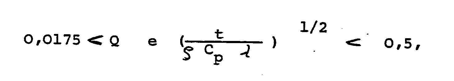
- the thermal treatment should preferably be carried out under the following conditions: where Q is the amount of heat supplied, per surface (end face) and time in J / m2s, e is the linear expansion coefficient of the rod material in l / K, t the duration of the heat in seconds, ⁇ the density of the rod material in kg / m3, C p is the specific heat of the rod material in J / kg K, and ⁇ is the thermal conductivity of the rod material in J / msK
- the method according to the invention is particularly successful when tubes made of a thermoplastic material are used which has an average linear expansion coefficient between 100 ⁇ 10 0 and 400 ⁇ 10 0 1 / K in the range between room temperature and melting temperature.
- the tube ends are at least partially heated to a temperature which is above the melting temperature of the tube material.
- the heat exchangers produced by the process according to the invention have an end face, that is to say on the surface in which the tubes end, a surface which is flush with the sleeve if the tube ends are positioned in the opening of the sleeve before the thermal treatment in such a way that the tube ends protrude 0.5 to 3 mm above the sleeve.
- the method according to the invention can be carried out most favorably if the tube ends are combined into a compact packing - in the case of circular or hexagonal outer cross sections of the tube ends into a packing with a hexagonal outer contour - before heat is supplied to them.
- Tubes are preferably used in the process according to the invention, the hydraulic diameter of each cavity between 0.3 and 15 mm, preferably between 0.5 and 7.5 mm, and the wall thickness at the thinnest point between 5 and 25%, preferably between 7 and 5 and l7.5% of the hydraulic diameter.
- sleeve used here is not limited to tubular bodies. It can also have the form of a plate which has a through opening which correlates with the outer contour of the tube bundle. A plurality of openings for one tube bundle each can also be provided in a plate. The sleeve can also be part of the heat exchanger housing comprising the tube bundle.
- the tube ends are positioned in such a way that they form an essentially flat surface before the thermal treatment, then this condition should also include that this surface can also be convex or concave.
- the sides of the hexagonal opening are all l2 mm long, with all corner points of the hexagon lying on a circle.
- the opening of the plate has a bevel toward the outside (end face), opposite bevels enclosing an acute angle of 45 °, and the bevel extends from the surface to a depth of 1.5 mm.
- the tube ends are positioned in the opening of the sleeve so that they protrude 0.5 mm from the edge of the sleeve.
- a round heating plate with a diameter of 100 mm which has an emission coefficient of 0.9 and was heated to a temperature of 430 ° C., was held for 2 minutes at a distance of 10 mm over the essentially upward ends of the tubes , causing the pipe ends to widen. After the tube ends and the sleeve have cooled, it can be determined that the tube ends are welded to one another or to the sleeve over a depth of 1.25 mm or to the sleeve.
- a tube group produced in this way can either be used alone, or several groups can be inserted next to one another in a heat exchanger housing.
- the five tubes 1 shown are positioned in a sleeve 2 - here designed as a plate - in such a way that the tube ends form a flat surface and project beyond the sleeve 2 by the amount s.
- a heated plate P - here shown in broken lines - is held at a distance d from above onto the pipe ends. As a result, the pipe ends l expand and fuse together.
- the pipe ends of the pipes 1 are connected to one another or to the sleeve 2.
- the points at which the pipe end of a pipe 1 is fused to the sleeve 2 is denoted by 3, at which two pipe ends are fused together, is denoted by 4.
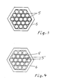
- FIG. 3 similar to FIG. 1, the arrangement of 19 tubes in a sleeve 6 with a hexagonal cross section before the thermal treatment is shown in a top view. This results in the densest packing for pipes with a circular cross-section.
Abstract
Wärmetauscher, bestehend aus mindestens einer Gruppe von Rohren (1) aus thermoplastischem Kunststoff, dadurch gekennzeichnet, daß die Rohrenden einer Gruppe dicht nebeneinander liegen und die Rohrenden benachbarter Rohre stirnseitig miteinander verschmolzen sind.Heat exchanger consisting of at least one group of pipes (1) made of thermoplastic material, characterized in that the pipe ends of a group lie close together and the pipe ends of adjacent pipes are fused together on the end face.
Bevorzugt sind die Rohrenden in einer die Rohrgruppe umfassenden Hülse (2) angeordnet, wobei außenliegende Rohrenden mit der Hülse verschmolzen sind.The tube ends are preferably arranged in a sleeve (2) comprising the tube group, outer tube ends being fused to the sleeve.
Die Wärmetauscher werden dadurch hergestellt, daß die Rohrenden zusammengefaßt und in eine Hülse eingeführt werden. Die Rohre werden in vertikaler Stellung (Rohrenden im wesentlichen nach oben) positioniert. Den Rohrenden wird dann von oben her Wärme zugeführt, wodurch sich die Rohrenden aufweiten und miteinander gegebenenfalls auch mit der Hülse verschmelzen. 
Description
Die Erfindung betrifft einen Wärmetauscher, bestehend aus mindestens einer Gruppe von Rohren aus thermoplastischem Kunststoff sowie ein Verfahren zum Herstellen dieser Wärmetauscher.The invention relates to a heat exchanger consisting of at least one group of tubes made of thermoplastic material and a method for producing these heat exchangers.
Die heute bekannten Wärmetauscher bestehen aus Rohren oder Rohrgruppen, welche in einen Rohrboden eingebettet sind. Dieser Rohrboden wird entweder getrennt hergestellt, wobei dann die Rohrenden mit dem Rohrboden verbunden werden müssen, oder der Rohrboden wird beim Herstellen des Wärmetauschers dadurch erzeugt, daß eine Vergußmasse zwischen die Rohrenden eingebracht wird. Die Herstellung solcher Wärmetauscher ist aufwendig, weil entweder die Rohre in den Rohrboden eingefädelt und positioniert werden müssen, bevor sie mit dem Rohrboden verbunden werden, oder die Rohrenden mit speziellen Vorrichtungen auf Abstand gehalten werden müssen, um die Vergußmasse (selbstaushärtendes Material oder Kunststoffschmelze) zwischen die Rohre einbringen zu können.The heat exchangers known today consist of tubes or tube groups which are embedded in a tube sheet. This tube sheet is either manufactured separately, in which case the tube ends must be connected to the tube sheet, or the tube sheet is produced when the heat exchanger is produced by introducing a casting compound between the tube ends. The production of such heat exchangers is complex because either the pipes have to be threaded into the tube sheet and positioned before they are connected to the tube sheet, or the tube ends have to be kept at a distance using special devices to prevent the casting compound (self-curing material or plastic melt) between the pipes.
Aufgabe der vorliegenden Erfindung ist es, einen Wärmetauscher zur Verfügung zu stellen, der besonders einfach herzustellen ist. Außerdem soll der erfindungsgemäße Wärmetauscher im Bereich des sonst üblichen Rohrbodens sehr kompakt ausgebildet sind. Es ist auch Aufgabe der vorliegenden Erfindung, ein besonders einfach zu bewerkstelligendes Verfahren zur Herstellung dieser Wärmetauscher zur Verfügung zu stellen.The object of the present invention is to provide a heat exchanger which is particularly simple to manufacture. In addition, the heat exchanger according to the invention is designed to be very compact in the area of the otherwise conventional tube sheet. It is also an object of the present invention to provide a method for producing these heat exchangers that is particularly simple to carry out.
Diese Aufgabe wird bei einem gattungsgemäßen Wärmetauscher dadurch gelöst, daß die Rohrenden einer Gruppe dicht nebeneinander liegen und die Rohrenden benachbarter Rohre stirnseitig miteinander verschmolzen sind. Ein solcher Wärmetauscher weist keinen herkömmlichen Rohrboden mehr auf.This object is achieved in a generic heat exchanger in that the tube ends of a group are close together and the tube ends of adjacent tubes are fused together on the end face. Such a heat exchanger no longer has a conventional tube sheet.
Bevorzugt sind die Rohrenden einer Gruppe von einer Hülse, welche zumindest teilweise aus thermoplastischem Material besteht, umfaßt, und sind die Rohrenden der zur Hülse benachbarten Rohre stirnseitig mit der Hülse verschweißt.Preferably, the tube ends of a group are surrounded by a sleeve, which consists at least partially of thermoplastic material, and the tube ends of the tubes adjacent to the sleeve are welded to the sleeve on the end face.
Die Kombination von Hülsen und Rohrenden macht eine kompakte Anordnung der Rohrenden möglich, ohne daß die am Eingang eines Wärmetauschers erforderliche Festigkeit und Dichtigkeit verloren geht.The combination of sleeves and pipe ends enables a compact arrangement of the pipe ends without losing the strength and tightness required at the entrance to a heat exchanger.
Bevorzugt bestehen die Rohrenden aus einem thermoplastischen Kunststoff, welcher im Bereich zwischen Raumtemperatur und Schmelztemperatur einen mittleren linearen Ausdehnungskoeffizienten zwischen l00 × l0⁻⁶ und 400 × l0⁻⁶ l/K besitzt.The pipe ends are preferably made of a thermoplastic material which has an average linear expansion coefficient between 100 × 10 0 and 400 × 10 0 / K in the range between room temperature and melting temperature.
In der Regel sind die Rohrenden mindestens bis zu einer Tiefe, die der dünnsten Wandstärke der Rohre entspricht, miteinander bzw. mit der Hülse verschmolzen.As a rule, the pipe ends are fused to one another or to the sleeve at least to a depth that corresponds to the thinnest wall thickness of the pipes.
Unter den Begriff "Wärmetauscher" fallen im Sinne der Erfindung auch Stoffaustauscher für Gase sowie Schalldampfer für Gas- oder Flüssigkeitsstrahlen.For the purposes of the invention, the term “heat exchanger” also includes substance exchangers for gases and mufflers for gas or liquid jets.
Unter den Begriff Rohre sind im Sinne der vorliegenden Erfindung zusammengefaßt alle rohrförmigen Körper, wie beispielsweise Rohre, Schläuche oder Hohlfäden. Die Querschnittsform der Rohre ist nicht auf kreisförmige Querschnitte beschränkt; die Rohre können auch elliptischen oder vieleckigen, beispielsweise dreieckigen, viereckigen, quadratischen, fünfeckigen usw. Querschnitt aufweisen. Die Wandstärke der Rohre, die sich aufgrund des Außen- und Innenquerschnitts der Rohre ergibt, kann über den Umfang der Rohre gleich oder unterschiedlich sein. Außen- und Innenquerschnitt der Rohre können dieselbe oder verschiedene Querschnittsform aufweisen. Beispielsweise kann ein Rohr im Außenquerschnitt eine vieleckige Kontur und im Innenquerschnitt eine kreisförmige oder elliptische Kontur aufweisen. Auch kann der Innenquerschnitt der Rohre einen oder mehrere durchgehende Hohlräume aufweisen. Die Rohre können auch zu Gruppen zusammengesetzt sein. Diese Rohrgruppen können beispielsweise äußerlich die Form einer Platte aufweisen, z.B. dann, wenn die Rohre achsparallel nebeneinander liegen und die Achsen auf einer geraden Linie angeordnet sind.For the purposes of the present invention, the term tubes includes all tubular bodies, such as tubes, hoses or hollow fibers. The cross-sectional shape of the tubes is not limited to circular cross-sections; the tubes can also have an elliptical or polygonal, for example triangular, quadrangular, square, pentagonal, etc. cross section. The wall thickness of the pipes, which results from the outside and inside cross section of the pipes, can be the same or different over the circumference of the pipes. Outside and inside cross-section of the tubes can have the same or different cross-sectional shape. For example, a tube may have a polygonal contour in the outer cross section and a circular or elliptical contour in the inner cross section. The inner cross section of the tubes can also have one or more continuous cavities. The tubes can also be put together in groups. For example, these tube groups can have the shape of a plate, e.g. when the pipes are parallel to each other and the axes are arranged on a straight line.
Eine besonders kompakte Form im Bereich der Hülse des erfindungsgemäßen Wärmetauschers ergibt sich dann, wenn der Innenquerschnitt der Hülse und der Außenquerschnitt aller Enden der in einer Hülse angeordneten Rohrgruppen die Form eines Sechsecks aufweist. Dies gilt besonders dann, wenn der Außenquerschnitt jedes Rohres oder jeder Rohrgruppe kreisförmig oder sechseckig ist. Für kreisförmigen Außenquerschnitt der Rohrenden ist das Sechseck Gewähr für die dichteste Packung der Rohrenden. Ein solches Sechseck weist in der Regel zumindest in etwa gleich lange Seiten auf. Jede Querschnittsform der Hülse ist allerdings geeignet, soweit die Rohrenden in kompakter Anordnung in die Hülse eingeführt werden können.A particularly compact shape results in the area of the sleeve of the heat exchanger according to the invention if the inner cross section of the sleeve and the outer cross section of all ends of the tube groups arranged in a sleeve have the shape of a hexagon. This is especially true when the outer cross section of each pipe or pipe group is circular or hexagonal. The hexagon is a guarantee for the circular outer cross section of the pipe ends densest packing of the pipe ends. Such a hexagon generally has sides of at least approximately the same length. Any cross-sectional shape of the sleeve is suitable, however, as far as the tube ends can be inserted into the sleeve in a compact arrangement.
Jede Röhrengruppe kann aus 7 bis ll4l Röhren bestehen.Each tube group can consist of 7 to ll4l tubes.
Der thermoplastische Polymerwerkstoff, aus dem Rohre und/oder Hülse bestehen, ist bevorzugt ein Polyäthylen, Polypropylen oder gehört zu den Fluorpolymeren. Die Rohre des Wärmetauschers weisen gewöhnlich keine Porosität oder eine Porosität von maximal 20% des Wandvolumens auf.The thermoplastic polymer material from which the pipes and / or sleeve are made is preferably a polyethylene, polypropylene or belongs to the fluoropolymers. The tubes of the heat exchanger usually have no porosity or a maximum porosity of 20% of the wall volume.
Die erfindungsgemäß gestellte Aufgabe wird auch gelöst durch ein Verfahren zum Herstellen eines erfindungsgemäßen Wärmetauschers, welches sich dadurch auszeichnet, daß die Rohrenden zumindest einer Seite der Rohre zusammengefaßt und derart in einer Hülse positioniert werden, daß die Rohrenden nahezu vertikal nach oben angeordnet sind, und die Rohrenden miteinander eine im wesentlichen ebene Fläche bilden, daß dann von oben her den Rohrenden soviel Wärme zugeführt wird, daß die Rohrenden mindestens teilweise erweichen und die Außenwände der Rohrenden sich derart erweitern, daß diese sich an die Außenwände benachbarter Rohrenden anlegen und mit diesen Rohrenden verschmelzen. Die Wärmezufuhr erfolgt in der Regel durch Wärmestrahlung. Bei Wärmestrahlung kann die Wärmezufuhr in einfachster Weise dadurch erreicht werden, daß eine Heizplatte von oben auf die Rohrenden zubewegt wird und in einem geringen Abstand, der im Bereich von 0,5 bis 30 mm liegt, solange positioniert wird, bis die Rohrenden miteinander verschmolzen sind. Man kann die thermische Behandlung auch unter Vakuum oder unter einer Schutzgasathmosphäre durchführen, wobei dann der Abstand der Heizplatte in anderen Bereichen liegen kann.The object of the invention is also achieved by a method for producing a heat exchanger according to the invention, which is characterized in that the tube ends are combined at least one side of the tubes and positioned in a sleeve such that the tube ends are arranged almost vertically upwards, and the Pipe ends form an essentially flat surface with one another so that heat is supplied to the pipe ends from above so that the pipe ends at least partially soften and the outer walls of the pipe ends expand such that they abut the outer walls of adjacent pipe ends and fuse with these pipe ends . The heat is usually supplied by heat radiation. In the case of heat radiation, the supply of heat can be achieved in the simplest way by moving a heating plate from above onto the pipe ends and at a short distance, which is in the range from 0.5 to 30 mm, until the pipe ends are positioned with one another are fused. The thermal treatment can also be carried out under vacuum or under a protective gas atmosphere, in which case the distance between the heating plate can be in other areas.
Die Wärmezufuhr kann aber auch durch Schallwellen, Licht, elektromagnetische Wellen, heiße Gase, heiße Flüssigkeiten o. ä. erfolgen. Wesentlich hierbei ist, daß die Rohrenden mit der eigentlichen Wärmequelle nicht in Berührung kommen.The heat can also be supplied by sound waves, light, electromagnetic waves, hot gases, hot liquids or the like. It is essential here that the pipe ends do not come into contact with the actual heat source.
Wenn bei dem erfindungsgemäßen Verfahren eine Hülse aus einem Werkstoff verwendet wird, an den die Rohrenden kaum oder gar nicht ankleben, so kann die Hülse nach dem Erkalten der mit einander verschmolzenen Rohrenden wieder abgezogen werden. Die miteinander verschmolzenen Rohrenden können dann in eine andere Hülse, beispielsweise in einen Rohrboden oder in einen Wärmetauscher mit Hilfe von herkömmlichen Verfahren eingebettet werden.If, in the method according to the invention, a sleeve made of a material is used to which the pipe ends hardly or not at all stick, the sleeve can be pulled off again after the pipe ends that have been fused together have cooled. The fused tube ends can then be embedded in another sleeve, for example in a tube sheet or in a heat exchanger using conventional methods.
Es hat sich als Vorteil herausgestellt, wenn die Rohrenden derart positioniert werden, daß sie mit der Hülse bündig oder die Hülse um bis zu 4 mm überragend angeordnet sind.It has proven to be an advantage if the pipe ends are positioned in such a way that they are flush with the sleeve or arranged so that they protrude by up to 4 mm.
Die Fläche der miteinander verschweißten Rohrenden weist dann eine hervorragende Festigkeit auf, wenn eine Hülse verwendet wird, die zumindest teilweise aus thermoplastischem Material besteht, und den Rohrenden soviel Wärme zugeführt wird, daß sich die der Hülse benachbarten Rohre an die Hülse anlegen und mit dieser verschmelzen.The surface of the tube ends welded to one another has excellent strength when a sleeve is used which is at least partially made of thermoplastic material and the tube ends are supplied with sufficient heat that the tubes adjacent to the sleeve abut and fuse with the sleeve .
Die thermische Behandlung soll bevorzugt unter Einhaltung folgender Bedingung durchgeführt werden:
e der lineare Ausdehnungskoeffizient des Stabmaterials in l/K,
t die Zeitdauer der Wärmeeinwirkung in sec.,
ρ die Dichte des Stabmaterials in kg/m³,
Cp die spezifische Wärme des Stabmaterials in J/kg K, und
λ die Wärmeleitfähigkeit des Stabmaterials in J/msKThe thermal treatment should preferably be carried out under the following conditions:
e is the linear expansion coefficient of the rod material in l / K,
t the duration of the heat in seconds,
ρ the density of the rod material in kg / m³,
C p is the specific heat of the rod material in J / kg K, and
λ is the thermal conductivity of the rod material in J / msK
Das erfindungsgemäße Verfahren gelingt vorzüglich, wenn Rohre aus einem thermoplastischen Werkstoff verwendet werden, welcher im Bereich zwischen Raumtemperatur und Schmelztemperatur einen mittleren linearen Ausdehnungskoeffizienten zwischen l00 × l0⁻⁶ und 400 × l0⁻⁶ l/K besitzt.The method according to the invention is particularly successful when tubes made of a thermoplastic material are used which has an average linear expansion coefficient between 100 × 10 0 and 400 × 10 0 1 / K in the range between room temperature and melting temperature.
Günstig ist es, wenn die Rohrenden zumindest teilweise auf eine Temperatur, die oberhalb der Schmelztemperatur des Rohrmaterials liegt, erhitzt werden.It is expedient if the tube ends are at least partially heated to a temperature which is above the melting temperature of the tube material.
Die nach dem erfindungsgemäßen Verfahren hergestellten Wärmetauscher weisen stirnseitig, das heißt auf der Fläche, in welche die Rohre enden, eine mit der Hülse bündig abschließende Fläche auf, wenn die Rohrenden vor der thermischen Behandlung derart in der Öffnung der Hülse positioniert werden, daß die Rohrenden die Hülse 0,5 bis 3 mm überragen.The heat exchangers produced by the process according to the invention have an end face, that is to say on the surface in which the tubes end, a surface which is flush with the sleeve if the tube ends are positioned in the opening of the sleeve before the thermal treatment in such a way that the tube ends protrude 0.5 to 3 mm above the sleeve.
Am günstigsten kann das erfindungsgemäße Verfahren dann durchgeführt werden, wenn die Rohrenden zu einer kompakten Packung - im Falle von kreisförmigen oder sechseckigen Außenquerschnitten der Rohrenden zu einer Packung mit sechseckiger Außenkontur - zusammengefaßt werden, bevor ihnen Wärme zugeführt wird.The method according to the invention can be carried out most favorably if the tube ends are combined into a compact packing - in the case of circular or hexagonal outer cross sections of the tube ends into a packing with a hexagonal outer contour - before heat is supplied to them.
Bevorzugt werden bei dem erfindungsgemäßen Verfahren Rohre verwendet, deren hydraulischer Durchmesser jeden Hohlraumes zwischen 0,3 und l5 mm, vorzugsweise zwischen 0,5 und 7,5 mm, und deren Wandstärke an der dünnsten Stelle zwischen 5 und 25%, vorzugsweise zwischen 7,5 und l7,5%, des hydraulischen Durchmessers liegt.Tubes are preferably used in the process according to the invention, the hydraulic diameter of each cavity between 0.3 and 15 mm, preferably between 0.5 and 7.5 mm, and the wall thickness at the thinnest point between 5 and 25%, preferably between 7 and 5 and l7.5% of the hydraulic diameter.
Der hier verwendete Begriff Hülse ist nicht beschränkt auf röhrenförmige Körper. Sie kann auch die Form einer Platte aufweisen, die eine mit der Außenkontur des Rohrbündels korrelierende durchgehende Öffnung aufweist. In einer Platte können auch mehrere Öffnungen für jeweils ein Rohrbündel vorgesehen sein. Die Hülse kann aber auch Teil des das Rohrbündel umfassenden Wärmetauscher-Gehäuses sein.The term sleeve used here is not limited to tubular bodies. It can also have the form of a plate which has a through opening which correlates with the outer contour of the tube bundle. A plurality of openings for one tube bundle each can also be provided in a plate. The sleeve can also be part of the heat exchanger housing comprising the tube bundle.
Wenn hier bei dem erfindungsgemäßen Verfahren ausgeführt wird, daß vor der thermischen Behandlung die Rohrenden derart positioniert werden, daß diese eine im wesentlichen ebene Fläche bilden, so soll diese Bedingung mit einschließen, daß diese Fläche auch konvex oder konkav ausgebildet sein kann.If, in the method according to the invention, it is carried out here that the tube ends are positioned in such a way that they form an essentially flat surface before the thermal treatment, then this condition should also include that this surface can also be convex or concave.
Die Erfindung wird anhand eines Beispiels näher erläutert.The invention is explained in more detail using an example.
Die Eigenschaften der in dem nachfolgenden Beispiel verwendeten Kunststoffe sind in der Tabelle zusammengestellt.

Ein Bündel von 9l Röhren aus PVDF Typ I, die einen Außendurchmesser von 2 mm und eine Wandstärke von 0,l5 mm aufweisen, werden derart zusammengefaßt, daß sie in eine sechseckige Öffnung einer Hülse aus PVDF Typ II, die eine Länge von 30 mm aufweist, eingeführt werden können. Die Seiten der sechseckigen Öffnung sind alle l2 mm lang, wobei alle Eckpunkte des Sechsecks auf einem Kreis liegen. Die Öffnung der Platte weist nach der Außenseite (Stirnseite) hin eine Abschrägung auf, wobei gegenüberliegende Abschrägungen einen spitzen Winkel von 45° einschließen,und die Abschrägung von der Oberfläche bis zu einer Tiefe von l,5 mm sich erstreckt. Die Rohrenden werden derart in der Öffnung der Hülse positioniert, daß diese die Kante der Hülse um 0,5 mm überragen.A bundle of 9l tubes made of PVDF type I, which have an outer diameter of 2 mm and a wall thickness of 0.15 mm, are combined in such a way that they fit into a hexagonal opening of a sleeve made of PVDF type II, which has a length of 30 mm , can be introduced. The sides of the hexagonal opening are all l2 mm long, with all corner points of the hexagon lying on a circle. The opening of the plate has a bevel toward the outside (end face), opposite bevels enclosing an acute angle of 45 °, and the bevel extends from the surface to a depth of 1.5 mm. The tube ends are positioned in the opening of the sleeve so that they protrude 0.5 mm from the edge of the sleeve.
Eine runde Heizplatte mit einem Durchmesser von l00 mm, welche einen Emissionskoeffizienten von 0,9 hat und auf eine Temperatur von 430°C erhitzt wurde, wurde 2 Minuten lang in einem Abstand von l0 mm über die im wesentlichen nach oben gerichteten Enden der Röhren gehalten, wodurch sich die Rohrenden erweiterten. Nach dem Abkühlen der Rohrenden und der Hülse kann festgestellt werden, daß die Rohrenden miteinander bzw. mit der Hülse über eine Tiefe von l,25 mm miteinander bzw. mit der Hülse fest verschweißt sind.A round heating plate with a diameter of 100 mm, which has an emission coefficient of 0.9 and was heated to a temperature of 430 ° C., was held for 2 minutes at a distance of 10 mm over the essentially upward ends of the tubes , causing the pipe ends to widen. After the tube ends and the sleeve have cooled, it can be determined that the tube ends are welded to one another or to the sleeve over a depth of 1.25 mm or to the sleeve.
Auf dieselbe Weise werden auch die gegenüberliegenden Rohrenden miteinander verbunden. Eine derart hergestellte Rohrgruppe kann entweder allein,oder es können mehrere Gruppen nebeneinander in ein Wärmetauschergehäuse eingesetzt werden.The opposite pipe ends are connected to each other in the same way. A tube group produced in this way can either be used alone, or several groups can be inserted next to one another in a heat exchanger housing.
Die Erfindung wird auch anhand von Figuren erläutert.The invention is also explained with reference to figures.
Es zeigen:
- Figur l eine Anordnung von bereits positionierten Rohrenden in einer Hülse vor der thermischen Behandlung im Querschnitt
Figur 2 die Anordnung gemäß Figur l nach der thermischen BehandlungFigur 3 eine Anordnung von bereits positionierten Rohrenden in einer Hülse vor der thermischen Behandlung in Draufsicht gemäß Figur lFigur 4 die Anordnung gemäßFigur 3 nach der thermischen Behandlung.
- Figure 1 shows an arrangement of already positioned pipe ends in a sleeve before the thermal treatment in cross section
- Figure 2 shows the arrangement of Figure 1 after the thermal treatment
- 3 shows an arrangement of already positioned pipe ends in a sleeve before the thermal treatment in a top view according to FIG
- Figure 4 shows the arrangement of Figure 3 after the thermal treatment.
In Figur l sind die fünf dargestellten Rohre l in einer Hülse 2 - hier als Platte ausgebildet - derart positioniert, daß die Rohrenden eine ebene Fläche bilden und die Hülse 2 um den Betrag s überragen. Zur thermischen Behandlung wird nun eine erhitzte Platte P - hier gestrichelt gezeichnet - in einem Abstand d von oben her auf die Rohrenden gehalten. Hierdurch erweitern sich die Rohrenden l und verschmelzen miteinander.In FIG. 1, the five
Nach der thermischen Behandlung sind die Rohrenden der Rohre l miteinander bzw. mit der Hülse 2 verbunden. Die Stellen, an denen das Rohrende eines Rohres l mit der Hülse 2 verschmolzen ist, ist mit 3, an denen zwei Rohrenden miteinander verschmolzen sind, ist mit 4 bezeichnet.After the thermal treatment, the pipe ends of the
Im Querschnitt kann man an den Verschmelzungsstellen 3 bzw. 4 erkennen, daß die Werkstoffe der beiden aneinander geschmolzenen Rohrenden derart sich miteinander vermischt haben, daß die Rohraußenwand nicht mehr erkennbar ist.In cross section one can see at the fusion points 3 and 4, respectively, that the materials of the two tube ends melted to one another have mixed together in such a way that the outer tube wall is no longer recognizable.
In Figur 3 ist - ähnlich wie in Figur l - die Anordnung von l9 Rohren in einer Hülse 6 mit sechseckigem Querschnitt vor der thermischen Behandlung in Draufsicht dargestellt. Hierbei ergibt sich die dichteste Packung für Rohre mit kreisförmigem Querschnitt.In FIG. 3, similar to FIG. 1, the arrangement of 19 tubes in a
Nach der thermischen Behandlung - wenn die Rohrenden der Rohre 5 miteinander verschmolzen sind - ergibt sich in Draufsicht eine Anordnung, wie sie in Figur 4 dargestellt ist. Sofern ein Rohr 5 mit sechs benachbarten Rohren 5ʹ verschmolzen ist, ergibt sich für das Rohr 5 in Draufsicht (auf die Stirnseite) eine sechseckige Kontur des Rohrendes. Für Rohrenden, die auch mit der Hülse 6 verschmolzen sind, ergeben sich die in Figur 4 ebenfalls dargestellten Konturen.After the thermal treatment - when the pipe ends of the
Claims (21)
e der lineare Ausdehnungskoeffizient des Stabmaterials in l/K,
t die Zeitdauer der Wärmeeinwirkung in sec.,
ρ die Dichte des Stabmaterials in kg/m³,
Cp die spezifische Wärme des Stabmaterials in J/kg K, und
λ die Wärmeleitfähigkeit des Stabmaterials in J/msK14. The method according to one or more of claims ll to l3, characterized in that the thermal treatment is carried out in compliance with the following condition:
e is the linear expansion coefficient of the rod material in l / K,
t the duration of the heat in seconds,
ρ the density of the rod material in kg / m³,
C p is the specific heat of the rod material in J / kg K, and
λ is the thermal conductivity of the rod material in J / msK
Applications Claiming Priority (2)
| Application Number | Priority Date | Filing Date | Title |
|---|---|---|---|
| DE3614339 | 1986-04-28 | ||
| DE19863614339 DE3614339A1 (en) | 1986-04-28 | 1986-04-28 | HEAT EXCHANGER AND METHOD FOR PRODUCING HEAT EXCHANGER |
Publications (3)
| Publication Number | Publication Date |
|---|---|
| EP0243574A2 true EP0243574A2 (en) | 1987-11-04 |
| EP0243574A3 EP0243574A3 (en) | 1988-10-19 |
| EP0243574B1 EP0243574B1 (en) | 1990-06-06 |
Family
ID=6299700
Family Applications (1)
| Application Number | Title | Priority Date | Filing Date |
|---|---|---|---|
| EP87100393A Expired - Lifetime EP0243574B1 (en) | 1986-04-28 | 1987-01-14 | Heat exchanger and method of producing heat exchangers |
Country Status (5)
| Country | Link |
|---|---|
| US (1) | US4867233A (en) |
| EP (1) | EP0243574B1 (en) |
| JP (1) | JPS62266392A (en) |
| DE (2) | DE3614339A1 (en) |
| DK (1) | DK65787A (en) |
Cited By (3)
| Publication number | Priority date | Publication date | Assignee | Title |
|---|---|---|---|---|
| EP0550078A1 (en) * | 1992-01-03 | 1993-07-07 | 3P-Consulting Inc. | Method for manufacturing a structural member and structural member formed by using said method |
| WO1993016346A1 (en) * | 1992-02-06 | 1993-08-19 | Aalander Johan | A method for manufacturing heat exchangers |
| FR3006232A1 (en) * | 2013-05-28 | 2014-12-05 | Bieder Alexandra Singer | PROCESS FOR ASSEMBLING PLASTIC TUBES FROM A SOURCE OF HEAT PERMITTING BY AUTOGENIC WELDING, OBTAINING A HOMOGENEOUS MATERIAL WITH AESTHETIC, MECHANICAL AND LIGHT QUALITIES |
Families Citing this family (15)
| Publication number | Priority date | Publication date | Assignee | Title |
|---|---|---|---|---|
| DE3806517A1 (en) * | 1988-03-01 | 1989-09-14 | Akzo Gmbh | PIPE BOTTOM FOR HEAT AND / OR FUEL EXCHANGERS, THE USE THEREOF AND THE METHOD FOR THE PRODUCTION THEREOF |
| SG52185A1 (en) * | 1993-02-04 | 1998-09-28 | Baxter Int | Elongate plastic member assembly and method and apparatus for making the same |
| US5840151A (en) * | 1993-02-04 | 1998-11-24 | Baxter International Inc. | Apparatus and dies for forming peelable tube assemblies |
| DE19529227C2 (en) * | 1995-08-09 | 1998-08-06 | Steag Ag | Storage block for regenerative heat exchangers |
| JPH09253945A (en) * | 1996-03-25 | 1997-09-30 | Ngk Insulators Ltd | Ceramics shell-and-tube heat exchanger with fins and manufacture thereof |
| JP3059393B2 (en) * | 1996-11-26 | 2000-07-04 | 日本ピラー工業株式会社 | Heat exchanger |
| DE60104895T2 (en) | 2000-10-06 | 2006-06-08 | E.I. Du Pont De Nemours And Co., Wilmington | HEAT EXCHANGER, MADE OF BENDING PLASTIC TUBES |
| US20030079872A1 (en) * | 2000-10-06 | 2003-05-01 | Kevin Bergevin | Refrigerant-capable heat exchanger made from bendable plastic tubing and method |
| JP3962018B2 (en) * | 2001-10-01 | 2007-08-22 | インテグリス・インコーポレーテッド | Thermoplastic resin heat exchanger and method for producing thermoplastic resin heat exchanger |
| EP1462163A4 (en) * | 2001-12-25 | 2005-04-27 | Wellness Co Ltd | Field converter and fluid processing device using the converter |
| KR101230694B1 (en) * | 2003-12-22 | 2013-02-07 | 엔테그리스, 아이엔씨. | Exchange devices with potted hollow conduits |
| US20060005955A1 (en) * | 2004-07-12 | 2006-01-12 | Orr Troy J | Heat exchanger apparatus and methods for controlling the temperature of a high purity, re-circulating liquid |
| US7458222B2 (en) * | 2004-07-12 | 2008-12-02 | Purity Solutions Llc | Heat exchanger apparatus for a recirculation loop and related methods and systems |
| GB0620512D0 (en) * | 2006-10-16 | 2006-11-22 | Sustainable Engine Systems Ltd | Heat exchanger |
| TWI392580B (en) * | 2010-07-09 | 2013-04-11 | Allied Supreme Corp | Fluorine resin pipe joint manufacturing method |
Citations (7)
| Publication number | Priority date | Publication date | Assignee | Title |
|---|---|---|---|---|
| US2433546A (en) * | 1943-12-11 | 1947-12-30 | Richard T Cornelius | Method and apparatus for forming plastic radiator cores |
| FR1135923A (en) * | 1954-08-30 | 1957-05-06 | Standard Thomson Corp | Improvements to heat exchanger cores and their manufacturing process |
| DE1209725B (en) * | 1960-03-11 | 1966-01-27 | Hans Joachim Dietzsch G M B H | Process for the surface treatment of a body made of bundled hollow threads |
| US3315740A (en) * | 1965-01-14 | 1967-04-25 | Du Pont | Flexible plastic tube bundle and method of making |
| US3462362A (en) * | 1966-07-26 | 1969-08-19 | Paul Kollsman | Method of reverse osmosis |
| DE2603615A1 (en) * | 1976-01-30 | 1977-08-11 | Masashi Kato | Thermoplastics tube bundles esp. for sewage filter bed - made by fusing together tubes at their ends |
| DE3338157A1 (en) * | 1983-10-20 | 1985-05-02 | Akzo Gmbh, 5600 Wuppertal | METHOD FOR SEALINGLY CONNECTING PIPE ENDS IN PIPE BASES |
Family Cites Families (33)
| Publication number | Priority date | Publication date | Assignee | Title |
|---|---|---|---|---|
| US2538808A (en) * | 1950-03-24 | 1951-01-23 | Westinghouse Electric Corp | Sealed heater element and the like |
| US2966373A (en) * | 1959-02-02 | 1960-12-27 | Ici Ltd | Tubular inserts |
| US3313740A (en) * | 1962-09-26 | 1967-04-11 | Gen Tire & Rubber Co | Expoxide polymerization catalysts, their preparation and their use |
| DE1238621B (en) * | 1963-04-13 | 1967-04-13 | Dom Techniczno Handlowy Przed | Device for cooling or warming the blood during surgical operations |
| US3347728A (en) * | 1964-07-29 | 1967-10-17 | Gen Motors Corp | Method for forming joints in tubes |
| US3459622A (en) * | 1966-11-07 | 1969-08-05 | Du Pont | Apparatus for the manufacture of plastic tube heat exchanger units |
| US3419069A (en) * | 1967-04-28 | 1968-12-31 | Du Pont | Heat transfer apparatus having flexible plastic tubular elements arranged in a braided configuration |
| US3435893A (en) * | 1967-07-31 | 1969-04-01 | Du Pont | Heat exchanger component formed with flexible plastic tubes |
| US3438434A (en) * | 1967-10-19 | 1969-04-15 | Du Pont | Subdivided heat exchanger tube bundle assembly providing longitudinally distributed fluid bypass and distributing channels |
| US3616022A (en) * | 1968-08-06 | 1971-10-26 | Du Pont | Method of making heat exchange components |
| US3592261A (en) * | 1968-11-25 | 1971-07-13 | Lummus Co | Heat exchanger |
| US3529664A (en) * | 1969-04-23 | 1970-09-22 | Du Pont | End structure for thermoplastic tubing |
| BE755779A (en) * | 1969-09-05 | 1971-02-15 | Westinghouse Electric Corp | APPARATUS FOR REVERSE OSMOSIS AND METHOD FOR MANUFACTURING IT |
| FR2088805A5 (en) * | 1970-04-24 | 1972-01-07 | Fabr Element Catalytiq | |
| US3708069A (en) * | 1970-08-13 | 1973-01-02 | Aqua Chem Inc | Reverse osmosis membrane module and apparatus using the same |
| US3718181A (en) * | 1970-08-17 | 1973-02-27 | Du Pont | Plastic heat exchange apparatus |
| GB1354502A (en) * | 1970-08-28 | 1974-06-05 | Ici Ltd | Heat exchangers |
| US3741849A (en) * | 1971-02-08 | 1973-06-26 | Angelica Corp | Method of joining tubes to manifold |
| DE2204167A1 (en) * | 1972-01-29 | 1973-08-09 | Krupp Gmbh | HEAT EXCHANGER AND PROCESS FOR ITS MANUFACTURING |
| DE2221951C2 (en) * | 1972-04-27 | 1983-04-28 | The Dow Chemical Co., 48640 Midland, Mich. | Membrane unit for cleaning a liquid mixture using reverse osmosis |
| US4098852A (en) * | 1972-07-04 | 1978-07-04 | Rhone-Poulenc, S.A. | Process for carring out a gas/liquid heat-exchange |
| FR2191091B1 (en) * | 1972-07-04 | 1975-03-07 | Rhone Poulenc Ind | |
| GB1478015A (en) * | 1973-07-27 | 1977-06-29 | Delanair Ltd | Heat exchanger |
| FR2273222B1 (en) * | 1974-05-30 | 1977-10-07 | Chausson Usines Sa | |
| DD121029A2 (en) * | 1975-06-19 | 1976-07-12 | ||
| GB1497204A (en) * | 1976-01-20 | 1978-01-05 | Kato M | Method for bundling tubes |
| US4047563A (en) * | 1976-01-27 | 1977-09-13 | Japan Medical Supply Co., Ltd. | Heat exchanger for artificial heart and lung devices |
| DE2612514B1 (en) * | 1976-03-24 | 1977-09-29 | Cenrus Ag | TUBE FLOOR OF A PIPE HEAT EXCHANGER |
| DE2734958A1 (en) * | 1977-08-03 | 1979-02-15 | Froehlich Air Ag | PROCESS FOR MANUFACTURING A PIPE HEAT EXCHANGER AND PIPE HEAT EXCHANGER MANUFACTURED BY THIS PROCESS |
| US4177816A (en) * | 1978-03-27 | 1979-12-11 | Sci-Med Life Systems, Inc. | Heat exchanger for blood |
| US4300971A (en) * | 1979-04-23 | 1981-11-17 | Mcalister Roy E | Method for manifolding multiple passage solar panel |
| US4481057A (en) * | 1980-10-28 | 1984-11-06 | Oximetrix, Inc. | Cutting device and method of manufacture |
| DE3240143A1 (en) * | 1982-10-29 | 1984-05-03 | Akzo Gmbh, 5600 Wuppertal | Process for embedding membranes in a thermoplastic material |
-
1986
- 1986-04-28 DE DE19863614339 patent/DE3614339A1/en not_active Withdrawn
-
1987
- 1987-01-14 EP EP87100393A patent/EP0243574B1/en not_active Expired - Lifetime
- 1987-01-14 DE DE8787100393T patent/DE3763109D1/en not_active Expired - Fee Related
- 1987-02-10 DK DK065787A patent/DK65787A/en not_active Application Discontinuation
- 1987-03-10 US US07/024,090 patent/US4867233A/en not_active Expired - Fee Related
- 1987-04-27 JP JP62102155A patent/JPS62266392A/en active Pending
Patent Citations (7)
| Publication number | Priority date | Publication date | Assignee | Title |
|---|---|---|---|---|
| US2433546A (en) * | 1943-12-11 | 1947-12-30 | Richard T Cornelius | Method and apparatus for forming plastic radiator cores |
| FR1135923A (en) * | 1954-08-30 | 1957-05-06 | Standard Thomson Corp | Improvements to heat exchanger cores and their manufacturing process |
| DE1209725B (en) * | 1960-03-11 | 1966-01-27 | Hans Joachim Dietzsch G M B H | Process for the surface treatment of a body made of bundled hollow threads |
| US3315740A (en) * | 1965-01-14 | 1967-04-25 | Du Pont | Flexible plastic tube bundle and method of making |
| US3462362A (en) * | 1966-07-26 | 1969-08-19 | Paul Kollsman | Method of reverse osmosis |
| DE2603615A1 (en) * | 1976-01-30 | 1977-08-11 | Masashi Kato | Thermoplastics tube bundles esp. for sewage filter bed - made by fusing together tubes at their ends |
| DE3338157A1 (en) * | 1983-10-20 | 1985-05-02 | Akzo Gmbh, 5600 Wuppertal | METHOD FOR SEALINGLY CONNECTING PIPE ENDS IN PIPE BASES |
Non-Patent Citations (1)
| Title |
|---|
| H. DOMININGHAUS: "Die Kunststoffe und ihre Eigenschaften", 1976, VDI-Verlag, Düsseldorf, DE * |
Cited By (4)
| Publication number | Priority date | Publication date | Assignee | Title |
|---|---|---|---|---|
| EP0550078A1 (en) * | 1992-01-03 | 1993-07-07 | 3P-Consulting Inc. | Method for manufacturing a structural member and structural member formed by using said method |
| WO1993016346A1 (en) * | 1992-02-06 | 1993-08-19 | Aalander Johan | A method for manufacturing heat exchangers |
| US5474639A (en) * | 1992-02-06 | 1995-12-12 | Alander; Johan | Method for manufacturing heat exchangers |
| FR3006232A1 (en) * | 2013-05-28 | 2014-12-05 | Bieder Alexandra Singer | PROCESS FOR ASSEMBLING PLASTIC TUBES FROM A SOURCE OF HEAT PERMITTING BY AUTOGENIC WELDING, OBTAINING A HOMOGENEOUS MATERIAL WITH AESTHETIC, MECHANICAL AND LIGHT QUALITIES |
Also Published As
| Publication number | Publication date |
|---|---|
| US4867233A (en) | 1989-09-19 |
| DK65787A (en) | 1987-10-29 |
| EP0243574B1 (en) | 1990-06-06 |
| DE3614339A1 (en) | 1987-10-29 |
| EP0243574A3 (en) | 1988-10-19 |
| DE3763109D1 (en) | 1990-07-12 |
| JPS62266392A (en) | 1987-11-19 |
| DK65787D0 (en) | 1987-02-10 |
Similar Documents
| Publication | Publication Date | Title |
|---|---|---|
| EP0243574B1 (en) | Heat exchanger and method of producing heat exchangers | |
| EP0243575B1 (en) | Heat and/or mass exchanger, and method of producing a heat and/or mass exchanger | |
| EP0226825B1 (en) | Method of joining hollow profiles and a plastics plate together, especially for manufacturing heat exchangers | |
| DE4039292C2 (en) | ||
| DE2814595C2 (en) | Method for manufacturing a pipe from thermoplastic material | |
| EP1358855A1 (en) | Process for manufacturing parts by freeform laser-sintering | |
| DE3104010A1 (en) | HEAT EXCHANGER TUBE AND HEAT EXCHANGER WITH COLLECTING PLATE AND MECHANICAL ASSEMBLY WITH THE HEAT EXCHANGER TUBE | |
| DE1080294B (en) | Method and device for producing hollow bodies from thermoplastic material | |
| DE4343825A1 (en) | Pipe-floor connection for a heat exchanger | |
| EP1980380A1 (en) | Device for warming or cooling, in particular as part of a mould for processing plastic masses, such as injection mould for plastic | |
| EP2307650B1 (en) | Linear connector for spacers in insulating glass panes, method for the manufacture thereof and for connecting two ends of a hollow profile member for a spacer using such a linear connector | |
| EP2159366B1 (en) | Method and device for producing a square spacer frame for insulating glass panes | |
| DE2646048B2 (en) | Device for producing tufted goods with a cavity | |
| EP0947659A2 (en) | Glass fibre reinforced spacer frame for insulating glazing and corner making method for the same | |
| EP0299182B1 (en) | Method of fusion-welding together tube ends and a tube plate | |
| DE2727666A1 (en) | CELL BOX FOR ACCUMULATORS AND PROCESS FOR ITS MANUFACTURING | |
| DE3117716A1 (en) | SOLAR COLLECTORS AND THEIR PRODUCTION | |
| WO2007088072A1 (en) | Connection between the end side of a plastic pipe and a plastic body | |
| CH663244A5 (en) | SPACERS FOR USE WITH WALL COMPONENTS. | |
| DE4303396A1 (en) | Pressing perforated objects | |
| DE2805545C3 (en) | Method and device for pressure welding at least one pipe to a plate | |
| DE3636177A1 (en) | Process, in particular for producing a heat exchanger, and a heat exchanger | |
| DE3742416A1 (en) | Process and apparatus for producing a profiled bar from thermoplastic material | |
| EP4214043A1 (en) | Device for controlling the temperature of a component, and method for producing the device | |
| DE2016581A1 (en) | Method and device for calibrating continuously extruded plastic pipe bodies |
Legal Events
| Date | Code | Title | Description |
|---|---|---|---|
| PUAI | Public reference made under article 153(3) epc to a published international application that has entered the european phase |
Free format text: ORIGINAL CODE: 0009012 |
|
| AK | Designated contracting states |
Kind code of ref document: A2 Designated state(s): AT BE CH DE FR GB IT LI NL SE |
|
| PUAL | Search report despatched |
Free format text: ORIGINAL CODE: 0009013 |
|
| AK | Designated contracting states |
Kind code of ref document: A3 Designated state(s): AT BE CH DE FR GB IT LI NL SE |
|
| 17P | Request for examination filed |
Effective date: 19881102 |
|
| 17Q | First examination report despatched |
Effective date: 19890209 |
|
| GRAA | (expected) grant |
Free format text: ORIGINAL CODE: 0009210 |
|
| AK | Designated contracting states |
Kind code of ref document: B1 Designated state(s): BE CH DE FR GB LI NL |
|
| GBT | Gb: translation of ep patent filed (gb section 77(6)(a)/1977) | ||
| ET | Fr: translation filed | ||
| REF | Corresponds to: |
Ref document number: 3763109 Country of ref document: DE Date of ref document: 19900712 |
|
| PLBE | No opposition filed within time limit |
Free format text: ORIGINAL CODE: 0009261 |
|
| STAA | Information on the status of an ep patent application or granted ep patent |
Free format text: STATUS: NO OPPOSITION FILED WITHIN TIME LIMIT |
|
| 26N | No opposition filed | ||
| PGFP | Annual fee paid to national office [announced via postgrant information from national office to epo] |
Ref country code: FR Payment date: 19931125 Year of fee payment: 8 |
|
| PGFP | Annual fee paid to national office [announced via postgrant information from national office to epo] |
Ref country code: CH Payment date: 19931129 Year of fee payment: 8 |
|
| PGFP | Annual fee paid to national office [announced via postgrant information from national office to epo] |
Ref country code: GB Payment date: 19931216 Year of fee payment: 8 |
|
| PGFP | Annual fee paid to national office [announced via postgrant information from national office to epo] |
Ref country code: DE Payment date: 19931217 Year of fee payment: 8 |
|
| PGFP | Annual fee paid to national office [announced via postgrant information from national office to epo] |
Ref country code: NL Payment date: 19940131 Year of fee payment: 8 |
|
| PGFP | Annual fee paid to national office [announced via postgrant information from national office to epo] |
Ref country code: BE Payment date: 19940628 Year of fee payment: 8 |
|
| PG25 | Lapsed in a contracting state [announced via postgrant information from national office to epo] |
Ref country code: GB Effective date: 19950114 |
|
| PG25 | Lapsed in a contracting state [announced via postgrant information from national office to epo] |
Ref country code: LI Effective date: 19950131 Ref country code: CH Effective date: 19950131 Ref country code: BE Effective date: 19950131 |
|
| BERE | Be: lapsed |
Owner name: AKZO N.V. Effective date: 19950131 |
|
| PG25 | Lapsed in a contracting state [announced via postgrant information from national office to epo] |
Ref country code: NL Effective date: 19950801 |
|
| GBPC | Gb: european patent ceased through non-payment of renewal fee |
Effective date: 19950114 |
|
| PG25 | Lapsed in a contracting state [announced via postgrant information from national office to epo] |
Ref country code: FR Effective date: 19950929 |
|
| REG | Reference to a national code |
Ref country code: CH Ref legal event code: PL |
|
| NLV4 | Nl: lapsed or anulled due to non-payment of the annual fee |
Effective date: 19950801 |
|
| PG25 | Lapsed in a contracting state [announced via postgrant information from national office to epo] |
Ref country code: DE Effective date: 19951003 |
|
| REG | Reference to a national code |
Ref country code: FR Ref legal event code: ST |