EP0242030A2 - Distributed telephone system - Google Patents
Distributed telephone system Download PDFInfo
- Publication number
- EP0242030A2 EP0242030A2 EP87301616A EP87301616A EP0242030A2 EP 0242030 A2 EP0242030 A2 EP 0242030A2 EP 87301616 A EP87301616 A EP 87301616A EP 87301616 A EP87301616 A EP 87301616A EP 0242030 A2 EP0242030 A2 EP 0242030A2
- Authority
- EP
- European Patent Office
- Prior art keywords
- channel
- control
- signals
- telephone
- voice
- Prior art date
- Legal status (The legal status is an assumption and is not a legal conclusion. Google has not performed a legal analysis and makes no representation as to the accuracy of the status listed.)
- Withdrawn
Links
Images


Classifications
-
- H—ELECTRICITY
- H04—ELECTRIC COMMUNICATION TECHNIQUE
- H04M—TELEPHONIC COMMUNICATION
- H04M9/00—Arrangements for interconnection not involving centralised switching
- H04M9/02—Arrangements for interconnection not involving centralised switching involving a common line for all parties
- H04M9/022—Multiplex systems
- H04M9/027—Frequency division multiplex systems
Landscapes
- Engineering & Computer Science (AREA)
- Signal Processing (AREA)
- Sub-Exchange Stations And Push- Button Telephones (AREA)
- Mobile Radio Communication Systems (AREA)
Abstract
A distributed telephone communication system (50) interconnects telephone units (52) via a single transmission line (56) providing full duplex communication between any pair of telephones (52). Each telephone (52) is coupled to the transmission line (56) by a control unit (54) which pages other control units (54) to initiate a telephonic communication. Each control unit (54) has an identification number and circuitry (60) for recognizing the identification number contained within a paging signal so as to initiate a response. In a separate spectral portion of the transmission line (56), there are provided sets of analog communication channels each of which has upper and lower spectral portions to provide two-way communication in opposite directions between a pair of tehephones (52) engaged in communication. A transmitter (22) and a receiver (23) in each of the control units (54) is provided for the communication of analog signals of both voice and date via the voice channel. Each control unit (54) includes circuitry (1A, 1B) for tuning the transmitter (22) and the receiver (23) to the selected channel in accordance with digital data transmitted via a transmission line (56) and specifying a selected one of the voice channels.
Description
- This invention relates to telephone systems for transmission of both voice and data and more particularly, to a system wherein all telephone sites are interconnected by a common coaxial transmission line with switching and routing functions being performed by on-site control units which couple the telephones to the transmission line.
- Presently, there are two basic types of telephone and data switching systems in use. The first type of system, which is the most widely used, incorporates central office switching. Such systems include the private branch exchange (PBX) which operates in the manner of a miniature central office. The second type of system is the local area network (LAN) which employs digitized voice and data transmission over a common cable.
- The central office or PBX type of system is characterized by the use of individual wires, such as a pair of wires or group of such pairs, to connect each telephone instrument to a central switch. The overall configuration of such a system has the form of a star with the central office switching at the middle and the individual telephone instruments being connected to the central office by their respective telephone lines. The central switch and its control equipment performs all of the necessary management functions for providing the voice and data communications, thereby allowing individual telephone instruments to communicate with any other one of the telephone instruments.
- In recent years, the telephone management functions, whether in a central office or in an on-site PBX, have been expanded to include a variety of sophisticated capabilities such as call forwarding, call camp-on, conference calling, call back, autodial, and least-cost routing as well as providing statistical information for efficient management of the system.
- The major disadvantages of the central switching approach arise from the dependence on the star wiring configuration, this resulting in an excessively large size and complexity to the central switch for the interconnection of thousands of telephone instruments. The star wiring configuration is not economical for small telephone systems. Furthermore, the star wiring configuration requires very large amounts of wire because the telephone line must extend from the location of each telephone instrument all the way to the central switch. Changes in the instrument may require new wiring as is the case when a call director instrument is substituted for a single line instrument necessitating the installation of multiple telephone lines. If the original single line instrument were re-installed, the surplus wire would be useless.
- Other disadvantages arise with the star wiring configuration in that dependence on the central switch causes system fragility because a switch failure shuts down the entire system. If more advanced functions are to be accommodated with the central switch, the switching equipment must contain a complex and powerful computer and very sophisticated software to manage the thousands of instruments simultaneously, as well as to switch voice traffic among them. Such complexity further decreases the reliability of the central office switch.
- The LAN arrangement incorporates a number of interconnected on-site PBX's via a common cable capable of high speed data transmission. Each PBX is substantially smaller than the usual central office switch. The resulting system has the form of clusters of star-wired PBX units connected to each other by a common cable network which may be configured in either the shape of a ring or a star configuration. While such a system may employ somewhat less wire than a central office system accommodating the same number of instruments, the system suffers, essentially, from the same disadvantages as the aforementioned central office system. Although each PBX unit is smaller and therefore less complex than the central office system, the PBX unit must be provided with the necessary functions to permit the unit to coordinate and connect with other ones of the PBX units.
- Another approach to the design of a LAN has been the use of a common cable to physically connect individual instruments or data terminals. Significantly, these systems have all relied on digital signal processing implementations to allow the multiplexing of both voice and data signals in high speed transmission bands of the common cable. Such digital signal processing has limited the practical capacity of the cable to a few hundred simultaneous conversations, in contrast with a desired capacity of carrying tens of thousands of conversations. The poor utilization of the digital approach results in such impracticality that the LANs have been used primarily to carry high speed data traffic instead of voice communication.
- Attempts have been made to enlarge the signal-carrying capacity of the cable by frequency division wherein plural transmission bands are provided to carry digital signals with the bands being spaced apart along the frequency spectrum. Such frequency division adds complexity to the coordinating and the connecting of communications among the plural transmission bands, thereby rendering such a system impractical for voice transmission. Additionally, broadband telephone transmission devices have heretofore required manual adjustment of their transmitting power levels to insure that all signals received on the common cable are of substantially the same strength. While the deployment of large numbers of such broadband devices throughout a telephone system would be desirable, the manual adjustment of power levels would render such deployment impractical.
- The foregoing disadvantages are overcome and other benefits are provided by a telephone system which, in accordance with the invention, is constructed with a transmission line that connects with the site of each telephone in the system. Preferably, a coaxial cable is employed as the transmission line. Connection of each telephone to the coaxial cable is accomplished via an intelligent control unit which controls all switching and routing of communication between the telephone and other telephones of the system.
- Both conversation and control signals are communicated via the coaxial cable. Voice and data signals in analog format are transmitted between telephones via any one of a set of relatively narrow bandwidth channels within the relatively broad frequency passband of the cable. A single channel of relatively wide bandwidth is reserved for the transmission of control signals in digital format.
- The system comprises many control units with one control unit being provided at each site. The control units are identical to one another. Each control unit can be employed with a telephone handset (or other source of telephonic signal such as a facsimile transceiver for the transmission and reception of picture information). Each control unit includes a microcomputer, two transmitters and two receivers. One of the transmitters and one of the receivers are used for the transmission and reception of radio-frequency (RF) narrow band telephone signals for voice and data communications. The second transmitter and the second receiver are used for wide band RF transmission and reception of control signals generated by the control units for the switching and the routing of the telephone signals on the narrow bandwidth channels.
- The microcomputer is programmed to perform the operations necessary to effect the various functions to be provided by the system, this programming including central-office Channel Status Table election and switching functions presently employed both in central offices and private branch exchanges. If desired, the system can utilize an existing two way coaxial cable system currently in use for the transmission of cable television or other communications. In particular, the microcomputer incorporates memory for storing the use and availability of the narrow band channels, and for selecting one of the channels in accordance with a pre-established protocol in response to a request to initiate a telephonic communication. The microcomputer also generates a data control word including an identification number of the telephone site which is to be called. The control word is received by all control units of the system, and the control unit at the desired site responds by way of a further control word identifying the channel to be utilized in the communication. If the telephone at the desired site is in use (line is busy), or if no person answers the phone, other control words are transmitted by way of response to indicate the condition of the telephone. It is noted that all control units receive all messages transmitted along the control signal channel including channel usage information, such information being most useful in the performance of more elaborate functions such as conference calling.
- The aforementioned aspects and other features of the invention are explained in the following description taken in connection with the accompanying drawing wherein:
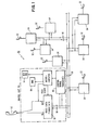
- FIGURE 1 shows the configuration of the system of the invention including a set of telephone instruments coupled by a corresponding set of control units to a common transmission line;
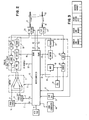
- FIGURE 2 is a block diagram showing components of a control unit of FIGURE 1;
- FIGURE 3 shows a data control word format for signals communicated between control units;
- FIGURE 4 shows a block diagram of a frequency synthesizer employed within the control units of FIGURE 2;
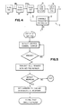
- FIGURES 5 and 6 are flow charts showing the operation of a microcomputer in the control units of FIGURE 2;
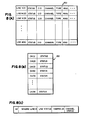
- FIGURE 7 is a graph showing spectrum utilization; FIGURE 8A is a schematic diagram of an exemplary Line Control Table maintained by microcomputer (processor) 15 shown in FIGURE 2;
- FIGURE 8B is a schematic diagram of an exemplary Channel Status Table maintained by microcomputer (processor) 15 shown in FIGURE 2;
- FIGURE 8C is a schematic diagram of an exemplary status update message format in accordance with the present invention;
- FIGURE 9 is a flowchart of some of the exemplary program control steps performed by the microcomputer (processor) 15 shown in FIGURE 2 when a message is received: and
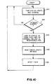
- FIGURE 10 is a flowchart of some of the exemplary program control steps periodically performed by the control unit shown in FIGURE 2.
- With reference to FIGURE 1, there is shown a
telephone system 50 constructed in accordance with the invention. Thesystem 50 includes a set oftelephone handsets 52, each of which is connected by acontrol unit 54 to acommon transmission line 56. Eachcontrol unit 54 includes atransceiver 58 for the reception and transmission of voice/data signals and atransceiver 60 for the transmission and reception of control signals. - Signals of a
handset 52 are converted to RF signals by thetransceiver 58, the RF signals then propagating along thetransmission line 56 to all of thecontrol units 54. In one of thecontrol units 54, thetransceiver 58 is tuned to the frequency of the RF signal and, in thatcontrol unit 54, thetransceiver 58 receives the RF signal and translates the signal back to audio frequency for reception by thehandset 52 connected to thatcontrol unit 54. - The
transmission line 56 has a bandwidth which is sufficiently wide to carry many channels, each of which is at a separate portion of the frequency spectrum, and each of which can carry a voice conversation between a pair of thecontrol units 54. In addition, the bandwidth of thetransmission line 56 is sufficiently wide to incorporate a broadband channel having sufficient bandwidth for the propagation of digital control signals between thetransceivers 60 and therespective control units 54. - The
transmission line 56 may be a coaxial cable or waveguide for the case of RF signal or, may be fabricated as an optical waveguide for the propagation of optical signals in which case thetransceivers transmission line 56 comprises a coaxial cable such as that utilized for the..two-way transmission of cable television programs. - In the use of the
system 50, control signals are transmitted along theline 56 to initiate a telephonic communication between a calling party (sender of the message) to another telephone (target which is to receive the message). Whilehandsets 52 are shown by way of example, it is to be understood that communication can be maintained between other devices (uch as facsimile in which signals are generated within the audio spectrum for transmission over the usual telephone channel). As will be described in further detail, the control signals transmitted between thetransceivers 60 are used for tuning thetransceivers 58 to a common channel so that persons located at the sender site and the target site can converse with each other. - In order to initiate a conversation, each
control unit 54 is provided with an identification number. Thus, when a sender wishes to call a target, the control signal transmitted by thesender transceiver 60 includes the identification number of thecontrol unit 54 associated with the target. - Referring also to FIGURE 2, there is provided a more detailed description of components of the
control unit 54. Eachcontrol unit 54 comprises twofrequency synthesizers 1 which are further identified by the legends A andB. Synthesizer 1A generates a carrier frequency in the upper half of a voice/data communication channel of theline 56 for the transmission of a message in one direction between the parties.Synthesizer 1B generates a carrier frequency at the lower half of the selected communication channel for transmission of the message in the reverse direction between the two parties. Thereby, by the use of the two carriers within the same communication channel, full duplex communication is attained. - Typically, a voice/data spectrum has a bandwidth in the range of 3000 hertz (Hz) to 3500 Hz. Two of the foregoing voice spectra are incorporated within a single communication channel to provide for the full duplex capability, the center frequencies of the two spectra being spaced apart in a range of 7 kilohertz (kHz) to 15 kHz with a nominal value of 10 kHz being utilized to inhibit crosstalk between the two spectra of the communication channel. As will be shown with reference to FIGURE 4, each of the
synthesizers 1 incorporates digital circuitry which is responsive to a multiple-bit digital signal provided by a set of Kl frequency-data input lines 2. - Each
control unit 54 further includes aselector switch 5 connected bylines 3 and 4 to the synthesizers lA-lB respectively. Theswitch 5 is operated in response to a signal on acontrol line 6. Theswitch 5 provides the capability of selecting either the upper or lower carrier frequency to be utilized for sending or receiving a message in accordance with a protocol to be described hereinafter. - The voice/
data transceiver 58 in eachcontrol unit 54 comprises ademodulator 8 and amodulator 9 which connect with the earpiece and mouthpiece, respectively, ofhandset 52. - Also included within the
transceiver 58 are aswitch 11, areceiver 12 and atransmitter 13. RF signals coupled to thetransceiver 58 by thetransmission line 56 are received by thereceiver 12, the RF signals then being demodulated by thedemodulator 8 and outputted alongline 7 to be converted into sound by thehandset 52. Signals spoken into thehandset 52 are inputted by aline 10 to themodulator 9 which then modulates the audio signal onto a carrier. The modulated carrier signal produced by themodulator 9 is coupled by theswitch 11 to thetransmitter 13 for transmission by thetransmission line 56 to adistant control unit 54 for communication with adistant handset 52. With the position of the switch contacts of theswitch 5 as portrayed in FIGURE 2, the carrier frequency produced by thesynthesizer 1A is employed by thedemodulator 8 in the demodulation of incoming RF signals while the carrier frequency produced by thesynthesizer 1B is employed by themodulator 9 in the generation of the outgoing RF signal. Typically, the modulation utilized by thedemodulator 8 and themodulator 9 is phase modulation, it being understood that other well-known forms of modulation may be utilized if desired. - The
control unit 54 further comprises a keyboard or keypad 14 andmicrocomputer 15, the keypad 14 being used by the sender party to enter the identification number into thecomputer 15 for the target party which is to be called. Thecomputer 15 is coupled by the foregoinglines synthesizers 1 and theswitch 5, and is also coupled by acontrol line 16 to theswitch 11 for initiating and terminating the connection of analog signals to the input terminal of thetransmitter 13. Thetransceiver 60 for the transmission and reception of control signals is coupled to themicrocomputer 15 bylines Line 17 couples incoming control data to themicrocomputer 15, while control data is outputted from the microcomputer vialine 18 to thetransceiver 60. - The
transceiver 60 comprises amodulator 19, ademodulator 20, aswitch 21, atransmitter 22 and areceiver 23. The components of thetransceiver 60 operate as do the corresponding components of thetransceiver 58 operate at a single carrier frequency. Themodulator 19 and thedemodulator 20 operate with FSK (frequency shift keying) or another well-known form of modulation for the transmission of digital data along thetransmission line 56. Acontrol line 24 from themicrocomputer 15 operates theswitch 21 to initiate and terminate the transmission of digital signals by thetransmitter 22. Control data signals initiated by themicrocomputer 15 are modulated onto a carrier by themodulator 19 and transmitted by theswitch 21 and thetransmitter 22 to theother control units 54 of thesystem 50. Control data signals emanating from other ones of thecontrol units 54 of thesystem 50 are received at thereceiver 23 and demodulated by thedemodulator 20 to be applied to themicrocomputer 15. - Signals coupled between the
transmission line 56 and each of thetransceivers variable attenuators attenuators lines microcomputer 15 to theattenuators attenuator 26 and thetransmission line 56 is made bycoaxial cable 27, and connection between thetransmission line 56 and theattenuator 29 is made bycoaxial cable 30. Theattenuator 26 is used for adjusting the intensity of signals transmitted by thetransceivers control units 54. Theattenuator 29 is utilized for adjusting the intensity of signals received from other ones of thecontrol units 54 to a suitable signal intensity for reception by thetransceivers - In view of the fact that all of the
control units 54 transmit over the same transmission channel, with respect to the transmission of the control data signals, eachmicrocomputer 15 monitors thetransmission line 56 for the presence of control data signals of other ones of thecontrol units 54 prior to the generation and transmission of a control data signal. The monitoring of thetransmission line 56 is accomplished by means of adetector 31 of the carrier of such other transmissions, thecarrier detector 31 being coupled to thereceiver 23 for the detection of the carrier of such other control data signal transmissions. Also included within eachcontrol unit 54 is anoscillator 32 for providing the carrier to themodulator 19 and thedemodulator 20 of thetransceiver 60. - The control data digital words transmitted between
transceivers 60 of thevarious control units 54 has the form presented in FIGURE 3. Such control word includes the line number identifying the sender, the line number identifying the target, a transacting code such as an indication that the party wishes to initiate a communication, and when required a channel number identifying the voice/data channel which is to be employed in communicating between two of thecontrol units 54. - In FIGURE 2, a
ring signal generator 64 provides a ring signal under command of themicrocomputer 15. In addition, themicrocomputer 15 can be employed for the introduction of audible signals to thehandset 52 via theline 33, such as when themicrocomputer 15 receives a data word via thetransceiver 60 indicating that the telephone at the desiredcontrol unit 54 is in use. - FIGURE 4 shows details in the construction of the frequency synthesizer lA. The
synthesizer 1B has the same form as thesynthesizer 1A and, accordingly, only thesynthesizer 1A will be described to facilitate the description of the invention. Thesynthesizer 1A comprises acrystal oscillator 66, a frequency divider 68, and a phase lockedloop 70. Theloop 70 comprises aphase detector 72, alow pass filter 74, a voltage controlledoscillator 76, and avariable frequency divider 78. In the preferred embodiment,oscillator 66 provides an output signal at a frequency of one megahertz which is applied to the divider 68. - Typically, the divider 68 comprises a counter, as is well known, which counts cycles of the oscillator output signal. By way of example, the divider 68 has a division ratio of forty resulting in an output signal of 25 kHz which is applied to the
phase detector 72 of theloop 70. - The voltage controlled
oscillator 76 applies an output signal to thedivider 78 which operates in a manner analogous to that of the divider 68 (except that the division ratio N ofdivider 78 is variable and if controlled by input Kl) to provide an output signal at a frequency of 25 kHz to the reference input terminal of thephase detector 72. Thedetector 72 provides a loop error signal proportional to the difference in phase between the input and reference signals, the error signal being filtered by thefilter 74 in a well known manner to provide a control voltage to theoscillator 76. Thereby, the frequency of theoscillator 76 is locked to the frequency at the output of the divider 68 by a fixed ratio, N. - The
divider 78 comprises well known digital counting circuitry wherein ratio N is established in accordance with digital words on the set oflines 2, these digital words being provided, as noted hereinabove, by themicrocomputer 15. The output frequency onlines 3 and 4 can be raised in increments of the 25 kHz frequency appearing at the input to thephase detector 72. - Assuming, by way of example, that the output frequency on
line 3 has a nominal value of 10 megahertz (MHz), then the aforementioned nominal value of 10 kHz between the transmission and reception portions of a voice channel can be accomplished by setting thesynthesizer 1B to a frequency which differs from that of thesynthesizer 1A by 10 kilohertz (kHz). Thereby, the carrier signals onlines 3 and 4 of FIGURE 1 differ in frequency by a nominal value of 10 kHz. As the carrier frequencies are scaled upwards and downwards by variations in the value of N, the frequency difference between the carriers inlines 3 and 4 remains constant. This provides a desired frequency spacing between the transmitted and received portions of a voice communication channel over a useful set of channels. The digital words onlines 2 select the desired channel and also set the carriers for the transmit and receive portions of the voice channels. Digitally controlled frequency synthesizers, such as thesynthesizer 1, are commercially available, such as that provided by Radio Shack in the citizen band radio model #TRC-451 or that provided by Heathkit (Health Corporation, Benton Harbor, Michigan, U.S.A.) in the "ham" radio model #HW-5400. - In operation, the
microcomputer 15 includes read-only memory (ROM) and random access memory (RAM) with conventional input/output circuitry necessary to exchange information with other components of thecontrol unit 54. The ROM contains programming logic which allows thecontrol unit 54 to interact with theother control units 54. The RAM provides facility for storing information, such as identification of the sender, unique to thecontrol unit 54. - Upon installation of the
system 50, eachcontrol unit 54 is provided with a unique "line" number, or identification number, which is entered into themicrocomputer 15 via the keypad 14, to be stored in the RAM of themicrocomputer 15. The keypad 14 may be of the standard form currently in use on pushbutton telephones. The line number is known to the users of thesystem 50 as the "telephone" number of the unit to be called as in any common telephone system. To facilitate an example in the use of thesystem 50, three of thecontrol units 54 have been further identified by the letters X, Y and Z, these three units having line identifications asline 210, line 320, and line 430, respectively. - The placement of a call between unit X and unit Z,
line numbers 210, and 430, respectively, would take place as follows. Thecontrol data receiver 23 in each of theunits 54 receives, over the control data channel, any words transmitted by other ones of thecontrol units 54. When a user at unit X wishes to connect unit X to unit Z, the user at X enters the number "430" into hismicrocomputer 15 via the keypad 14. Themicrocomputer 15 then checks thedetector 31 for the presence of a carrier on the control data channel. - When no carrier is detected, the
microcomputer 15 activates theswitch 21 to transmit a control data word, having the format disclosed in FIGURE 3, via themodulator 19 and thetransmitter 22; thereafter, themicrocomputer 15 turns off theswitch 21 to terminate any further transmission. All of theunits 54 receive the transmission from the sender via thetransmission line 56. - In accordance with a feature of the invention, each of the
units 54 maintains, in the computer memory RAM, a table of the busy/free status of all voice communication channels of thesystem 50. Themicrocomputer 15 in eachunit 54 is also programmed to select, from the data received via thereceiver 23, the information needed to maintain the status of other ones of theunits 54. Whenmicrocomputer 15 of unit Z receives the control data word transmitted by unit X, themicrocomputer 15 of unit Z can then process the "call request". Themicrocomputer 15 of unit Z then selects a currently free channel from the Channel Status Table and transmits along the transmission line 56 a data control word containing the sender's line number (430 for unit Z), the target line number (210 for unit X), the transaction code for "accepting call", and the channel number to be used for the call. - Upon receiving this control data word, the
microcomputers 15 in all of thecontrol units 54 designate the selected channel as being busy. Also, themicrocomputer 15 in unit X sets the frequency-data input lines 2 for the frequency synthesizers lA-lB to the selected channel. - In accordance with a further feature of the invention, a protocol is established for each pair of
units 54 communicating with each other wherein eachunit 54 of the pair ofcontrol units 54 sets itsselector switch 5 for transmission on the upper half of the voice/data channel if its "telephone line" number is higher than that of the other unit of the pair ofcontrol units 54, and to receive on the upper half of the voice/data channel if the line number of thecontrol unit 54 is lower than that of the line number of the other unit of the pair ofcontrol units 54. In the foregoing example, unit Z has a higher number than unit X. Accordingly, unit Z will transmit on the upper portion of the selected communication channel to unit X which is tuned to receive on the upper portion of the communication channel. Unit X will transmit on the lower portion of the communication channel to unit Z which will receive on the lower portion of the communication channel. This provides for the full duplex transmission/reception between the units X and Z. - As the two
control units 54, namely the units X and Z, communicate with each other via the voice/data channel by use of thetransceiver 58, the two units can communicate simultaneously via the control data channel by thetransceivers 60. This capability of control data word exchange betweenautonomous control units 54 even while full duplex conversations, voice or data, are taking place under control of programming in themicrocomputers 15 allows the implementation of advanced PBX functions, and also permits eachcontrol unit 54 to maintain system status tables such as those required multiple-line telephones as well as maintaining the status of each communication channel. - With respect to the control of power levels by use of the
attenuators transceivers 60. A requested increase or decrease in transmitted power can be communicated by use of the appropriate transaction code in the format of FIGURE 3. Thereby, power of aremote control unit 54 can be increased or decreased if necessary to improve communication with anothercontrol unit 54. - The flow chart of FIGURE 5 describes the operation of the
microcomputer 15 in thecontrol unit 54 of the sender party requesting a communication. The telephone number is entered at the keypad to alert themicrocomputer 15 that a telephone call to a remote instrument is desired. Thereupon themicrocomputer 15 samples the output signal of thedetector 31 to determine whether a carrier is present on the control data channel. Themicrocomputer 15 continues to monitor the control data channel until it is free of the presence of a carrier from someother control unit 54. Thereupon themicrocomputer 15 initiates a control word with the format of FIGURE 3 to transmit a call request to all of thecontrol units 54. Thecontrol unit 54 having the designated telephone number, the target party, then transmits a response to the sender. In the event that themicrocomputer 15 does not receive a response, then the sending party is alerted of a failure to communicate, whereupon the sending party could again dial the telephone number. In the event that a response is received, such response contains the identification of the channel to be used for the communication and, accordingly, themicrocomputer 15 commands thefrequency synthesizers transceiver 58 to the appropriate channel. Then, the sending party can communicate by speaking into thehandset 52. - The flow chart of FIGURE 6 describes the operation of the
microcomputer 15 of the target party. An incoming control word having a transaction code indicating that a telephone communication is desired, and also having a target line number is processed by themicrocomputer 15 to determine whether the target line number is identical to that of thecontrol unit 54. If the number is identical, then thecontrol unit 54 is alerted by themicrocomputer 15 to the fact that it is the target party with whom a telephone call has been requested and, accordingly, themicrocomputer 15 verifies if this unit is busy and if so sends a "busy" answer. - If idle this unit's
microcomputer 15 sends an answer indicating that this unit is "ringing" and then activates thegenerator 64 to ring. Such answers, in the form of control words, are transmitted only after a monitoring of thetransmission line 56 determines that noother control units 54 are transmitting along the control data channel. In the event that the handset is lifted, then thetarget microcomputer 15 reads its memory, namely the RAM, to determine which voice/data channels are available and to select one such channel for the telephonic communication. - The
microcomputer 15 commands the appropriate frequencies from thesynthesizers 1A-1B for the selected channel, and also transmits a control word to the sender party designating the selected communication channel. The notification of the sending part of the desired channel is accomplished only after a checking of thetransmission line 56 to determine whether any carrier is present from a communication of anothercontrol unit 54. The process of waiting for a free time slot on the control data channel insures that control information can be transmitted among thevarious control units 54 without any interference among the signals of thevarious control units 54. - The system of the invention presents a new approach to telephone switching and transmission. The inclusion within each control unit of a computer with memory and with a capacity for monitoring the status of the various communication channels provides intelligence to the control unit. The connection of the control units to a common coaxial cable introduces a wiring configuration such as that utilized in conventional two-way cable television systems. Each control unit has sufficient intelligence and switching capability to connect itself to any other control unit to establish two-way communication. This is accomplished without any telephone central switching system and, accordingly, there is no such central switch in the system of the invention.
- Inefficiencies associated in the operation of a star wiring configuration with a central switch are not present with the system of the invention and, in addition, the complexity and fragility of the central switch are eliminated. The voice transmissions are performed in an analog fashion rather than in the digital fashion which would require a much broader bandwidth and a time division multiplexing of the signals of the various conversations being carried by the telephone system. Accordingly, the system of the invention can carry many more conversations simultaneously, the number of simultaneous conversations being increased by an order of magnitude.
- A single digital transmission channel is employed for the coordination of the individual control units. Thus, the system of the invention can perform all of the usual switching and transmission functions, as well as more advanced switching and transmission functions, by simply programming the microcomputer. The units can also adjust the power level of transmitted signals as required, and can also maintain data and statistics on the use of the various communication channels.
- With reference to FIGURE 7, there is shown a graph portraying the utilization of the frequency spectrum for the various voice/data channels and the control data channel. FIGURE 7 shows two of the many voice channels and the control data channel. The bandwidth of a voice channel is substantially less than that of the control data channel. The channels carrying the voice and/or data are divided into an upper portion and a lower portion, with the two portions being spaced apart in the frequency domain by a protection band to inhibit crosstalk between signals propagating along the transmission line 56 (FIGURE 1) in the upper portion and in the lower portion of the voice channel.
- The protocol for assignment of the foregoing portions of the voice channel for transmission and reception by one of the control units 54 (FIGURE 1) is also shown in FIGURE 7. In the upper portion of a voice channel, there is transmission of an analog signal by the control having the higher identification number, with the analog signal of the upper portion being received by the control unit having the lower identification number. Correspondingly, in the lower portion of the channel, there is transmission of an analog signal by the control unit having the lower identification number, with the analog signal of the lower portion being received by the control unit having the higher identification number. Thereby, FIGURE 7 demonstrates the inventive feature of full duplex communication.
- With respect to the installation of the
system 50, a telephone and its control unit can be installed in a home, an office, and other locations where telephones are employed. The coaxial cable which serves as the transmission line may be supported on telephone poles or placed under ground. Each telephone with its control unit may be regarded as a station for the transmission and reception of information. The identification number identifies the station, and the interchangingof the handset, or the adding of additional stations does not alter the identification number. Also, the interposition of facsimile device for the transmission of pictorial data in lieu of the handset for the transmission of voice would not alter the identification number since it is allocated with the control unit. - All transmissions of a control unit, whether on a voice channel or a control channel, propagate to all of the other control units in the system. Therefore, the initiation of a telephone call is in the nature of a paging of the desired party, which paging is "heard" by all parties. In the case of the control channel, only the control units having the called identification number respond. In the case of the voice channel, only the control unit which is tuned to the voice channel participates in the full duplex communication. The selection of the upper and lower portions of each voice channel to be designated for transmitted and received messages is accomplished in accordance with the protocol based on the relative magnitudes of the identification numbers of the sender and target parties.
- As mentioned above, the present invention provides a fully distributed telephone system with full PBX functions (including advanced functions such as autodial, redial, call forward/routing, call waiting, camp-on, message forwarding and display, hold, hunt groups, route on ring no answer, conference calling, least cost routing, break-in, intercom, priority calling and the like). Further details of the novel architecture in accordance with the present invention and a description of the manner in which
telephone control units 54 are synchronized will now be presented. - Each
control unit 54 shown in FIGURE 1 is assigned a nominal "home line" preferably corresponding to an extension number (e.g., a combination of four digits such as 3344). In conventional telephone systems, every extension "line" corresponds to a physical wire pair. In the present invention, a "line" is simply a unique designation used to describe one or a group ofcontrol units 54. As described above, voice information may be directed to and from any "line" via any one of the voice channels provided bysystem 50. - In conventional telephone systems, more than one telephone unit may be connected to the same "line." For example, many homes have more than one "extension" connected to the same telephone wire pair. All such extensions have the same telephone number. In PBX systems, it may be desirable to assign a particular telephone "line" to one telephone unit, while also connecting that "line" to several other telephone units (which may be considered "extensions" on the same "line"). For example, the direct dial "line" of a business executive is connected to the telephone unit(s) within the executive's office and also to the telephone unit of the executive's secretary. The telephone unit within the executive's office may be termed the "home" unit for the "line", and the telephone unit of the executive's secretary may be termed an "extension" on the same "line." The telephone unit of the executive and the telephone unit of the secretary may both include an indicator lamp which lights when the "line" is off-hook, and either unit may be used to make/answer calls on the "line."
- It may be desirable to ring a bell or other ringing device in both telephone units when a call is received on the "line." Alternatively, it may be desirable to ring only the "home unit" (i.e., the telephone unit within the executive's office) when a call is received, and to route the call to the secretary's telephone unit (to cause that unit to ring) if the executive's unit does not go off-hook within a predetermined number of rings (this feature is known as "route on ring no answer"). Those skilled in the art are aware of many other variations and arrangements provided in conventional PBX systems to add versatility and usefulness. Such advanced PBX function can be easily implemented by the system of the present invention due to its flexible message capabilities.
- Each
control unit 54 of the preferred embodiment (see FIGURE 2) stores and maintains, preferably in an internal random access memory internal to microcomputer (processor) 15, a Line Control Table 100 (see FIGURE 8a) which enables the control unit to behave as an "extension" of one or more "lines". Line Control Table 100 serves two functions in the preferred embodiment: it designates which extension numbers eachcontrol unit 54 monitors; and it stores status and other information about the monitored lines. - The exemplary Line Control Table 100 shown in FIGURE 8A includes a "LINE" field, a "STATUS" field, a "CID" field; a "CHANNEL" field, a "TYPE" field and a "RING" field. A different "line" ("extension") designation is stored in the "LINE" field of each of the entries in Table 100. In the preferred embodiment, these "LINE" fields store 4-digit "line" numbers or designations which serve as unique "addresses" in
system 50. Single or groups ofcontrol units 54 are designated by referring to the line numbers allocated to them (e.g., one or more control units may monitor "line" 3344, which line number serves as unique address designating that unit or group of units). - The "STATUS" field of each entry of Line Control Table 100 stores one of two values: "idle" or "busy." Such "STATUS" fields indicate the status (in use or not in use) of the "line" designated by the information stored in the associated "LINE" field.
- If a line is in use, the "CID" field associated with that line stores the number of the line connected thereto (in
system 50, a line generally cannot be in use unless it is engaged in voice information exchange with another "line"). Similarly, the "CHANNEL" field associated with a line in use stores the voice channel number used to communicate information between the line and the further line identified by the "CID" field. The "CID" and "CHANNEL" fields associated with a line not in use are null. - The "TYPE" field contains one of two values in the preferred embodiment: "home" or "monitored". In the preferred embodiment, every "line" has one and only one "home"
control unit 54, but may also be "monitored" by any number of additional control units. Somecontrol units 54 may have no "home" lines while other control units may have several such "home" lines. Certain PBX functions affecting a particular line can be initiated only by the "home"control unit 54 of that line (e.g., it may be desirable to cause only a "home" unit of a line to ring in response to an incoming call on the line, and to merely flash a lamp for the control units which store the designation "monitor" in the "TYPE" field of an entry in their Line Control Table 100 associated with the "ringing" line). - Exemplary Line Control Table 100 also includes an "ring" field associated with each entry which stores one of two values: "yes" (indicating that the associated line is ringing; and "no" (indicating that the associated line is not ringing). Additional fields may be provided in Line Control Table 100 to implement special functions (e.g., call forwarding, intercom, etc.).
- The contents of the Line Control Table 100 can be dynamically changed by the
control unit 54. For example, the "status", "CID" and "CHANNEL" fields associated with a particular line are updated in accordance with the instantaneous status of that line (the manner in which this information is updated will be discussed in detail shortly). Acontrol unit 54 preferably never changes certain information in its Line Control Table 100 (for example, the number of entries in the Line Control Table and the contents of the "line" fields of the entries), although even these parameters are variable (and are preferably set when thecontrol unit 54 is initially programmed and installed). - As mentioned previously, each
control unit 54 also maintains (in a random access memory internal toprocessor 15 in the preferred embodiment) a "Channel Status Table" 150 (see FIGURE 8b). Channel Status Table 150 in the preferred embodiment simply stores the status ("busy" or "idle") of each and every voice channel ofsystem 50. - Versions of Table 100 and 150 are independently stored within each of
control units 54, and are independently updated by the control units in response to messages broadcast over the control channel. - As mentioned previously, messages are transmitted over the control channel by
control units 54 in the preferred format shown in FIGURE 3. Each message includes at least a "transaction" code (e.g., ring, status update, terminate call, or the like); a "sender line number" (the number of the line thecontrol unit 54 originating the message is to affect); a "target line number" (the designation of the control unit or group of control units intended to receive the message); and a "channel number" (the designation of the voice channel to be used for communicating voice information between the sender "line" and the target "line"). - For example, suppose a
first control unit 54 monitoring line number 2233 is placed "off-hook" in response to a received message from a further control unit monitoring line number 4567 initiating a call to line 2233. As discussed above, the proper response of thefirst control unit 54 is to send a "ringing response" message (action code = RR) to line number 4567 originating the call. Such an exemplary message would appear as follows: -

first control unit 54 onto the system control channel and thus would be broadcasted to and received by everycontrol unit 54 which is active and capable of receiving messages. - FIGURE 9 is a flowchart of some of the exemplary control function steps performed by
processor 15 of eachcontrol unit 54 of the preferred embodiment upon receipt of a message broadcast on the control channel. -
Control units 54 inspect every received message to determine whether the status (idle or busy) of a channel is affected (decision block 202) by the message. If the received message does affect the status of one of the voice channels ofsystem 50, thecontrol unit 54 determines whether it is itself using the channel the status of which being updated by the received message (decision block 204). If thecontrol unit 54 is not using the updated channel, it simply updates its status control table 150 to reflect the new channel status (block 206). - As will be explained shortly, it is possible in the preferred embodiment for a
control unit 54 not currently using or attempting to use a particular voice channel to transmit a message purporting to set or verify the status of the channel. If acontrol unit 54 using a voice channel receives a message purporting to set a status for that channel which conflicts with its own use (block 208), the receiving control unit transmits a "status update" message to correct the conflicting channel status information which has now been stored in everycontrol unit 54 of system 50 (including the control unit which originated the incorrect message) in response to the prior, incorrect message (block 210). In this way, incorrect channel status information is promptly corrected for everycontrol unit 54 ofsystem 50. Moreover, eachcontrol unit 54 is able to independently maintain its own Channel Status Table 150 and independently determine which voice channels are idle and which channels are busy. - After Channel Status Table 150 has been updated,
control unit 54 determines whether the received message affects either its "home" line or a line which it monitors (decision block 212) by comparing line number information contained in the received message to the "line" fields of the control unit Line Control Table 100. If neither the "sender line number" nor the "target line number" contained in the received message match a "line" field of the Line Control Table 100, the message does not affect any "home" or monitored line of the control unit, and no further action needs to be taken in response to the received message. On the other hand, if one or both of the "sender line number" and "target line number" fields of a received message match a "line" field of the receivingcontrol unit 54 Line Control Table 100, the Line Control Table is updated in accordance with the received message and/or the receiving control unit may be required to take other action (e.g., light an indicator lamp, send a responsive message, or the like) in response to the message. - If a match exists between one of the line numbers referenced by the received message and a "line" field of the Line Control Table 100 of the receiving
control unit 54, the control unit inspects the action code field of the received message to determine what type of processing needs to be performed (for example, answer a call, ring a bell, disconnect, or the like) (block 214). Next, the entry (entries) of Line Control Table 100 corresponding to the line(s) referenced by the received message is (are) accessed to determine the precise action, if any, which should be performed in response to the received message (block 216). For example, if the received message action code specifies that a particular line number is to ring, the receivingcontrol unit 54 writes a "yes" into the "ring" field of the entry of the Line Control Table 100 corresponding to the target line number field of the received message (assuming such an entry does, in fact, exist in the Line Control Table) and activatesring signal generator 64 to provide an audible ring signal. Line Control Table 100 may determine the "personality" of thecontrol unit 54 within which it is stored and cause the control unit to perform appropriate actions (e.g., send a message if a message is needed) based on the action code of the received message and the information stored in its own Line Control Table 100 (block 218). - For example, suppose the action code of a received message indicates a call request to line 0006 and the Line Control Table 100 of receiving
control unit 54 includes an entry having a "line" field = 0006, a "status" field = "idle," and a "type" field = "home." The receivingcontrol unit 54 performs the necessary processing to answer the incoming call, such as sending a "ring response" message to the sending line number indicating a positive response that the telephone is ringing, actuating itsring signal generator 64, and lighting an appropriate indicator light. As mentioned above, the "ring response" message is sent with the number of a free channel (selected from one of the free voice channels indicated by the Channel Status Table 150 of the control unit 54) to be allocated for the call. The Line Control Table 100 and the Channel Status Table 150 ofcontrol unit 54 are then updated to reflect the new activity, e.g., the entry corresponding to the selected channel is marked "busy" in the Channel Status Table, and the line is marked in the Line Control Table as having a "busy" status, a "CID" = the line number initiating the call, and a "channel" = channel to be used for the call (blocks 220, 222). - If, however, the receiving
control unit 54 contains an entry in its Line Control Table 100 having a "line" field = 0006 and a "type" field = "monitor", the control unit does not need to perform any steps to process the received message (unless, for example, it is supposed to ring along with the "home" unit of that line). If and when the "home" control unit sends a "ringing response" message, the control unit monitoring the effected line updates its Line Control Table 100 and Channel Status Table 150 appropriately to indicate that the voice channel number selected by the "home" control unit is busy and line 0006 is busy on that voice channel communicating with the line originating the call. - Thus, each control unit of
system 50 receives every message transmitted over the control channel, but processes only two types of messages -those messages which affect the status of a voice channel, and those messages which refer to a line number corresponding to an entry in the receiving control unit's Line Control Table 100.Control units 54 simply ignore messages which do not affect lines not monitored by them (or affecting "home" lines), except to the extent that such messages contain channel status information. Eachcontrol unit 54 is accurately updated with the status of all of the components ofsystem 50 relevant to its own operation and therefore remains in perfect synchronization while functioning completely independently of every other component in the system. - It is not necessary for each
control unit 54 to maintain a complete list of the multiple occurrences of every line in thesystem 50. Moreover, the message protocol of the present invention does not require acknowledgements of every message, thereby reducing system message traffic and eliminating the need for multiple acknowledgements of a single message. The amount of processing time and processor memory resources devoted to maintaining Tables 100 and 150 are minimized, thereby increasing efficiency and decreasing equipment cost. - No centralized "master" status table is maintained in the preferred embodiment of
system 50. Rather, eachcontrol unit 54 independently maintains tables containing only the control information relevant to its own operation. Sometimes,individual control units 54 may fail to receive one or more messages transmitted over the control channel ofsystem 50, causing them to become unsynchronized with the remainder of the system. For example, acontrol unit 54 which is temporarily disconnected fromsystem 50 will no longer be synchronized (even if it equipped with a non-volatile random access memory storing Tables 100 and 150) because it cannot update its stored table information in response to changes in line and channel status. Power failures can causemany control units 54 to go "off line" at once. When power is restored, the "off line" units all go back "on line" at about the same time, and all must quickly update their status information in order to operate properly. - The preferred embodiment of
system 50 includes a facility distributed throughout thecontrol units 54 of the system for maintaining the independent control units in synchronization with one another despite temporary failure of some or most of the control units. - In the preferred embodiment, ongoing resynchronization is accomplished through a "status update message." Each
control unit 54 ofsystem 50 periodically broadcasts a "status update control message" containing information specifying its own status (e.g., ringing, busy, idle, etc.). Each voice channel is also arbitrarily assigned to at least onecontrol unit 54 given the responsibility of updating the status of its assigned voice channel (for example, by storing an additional bit or field in the assigned unit's Channel Status Table 150 indicating that it is assigned to update the status of a particular voice channel). Voice channels are assigned arbitrarily to controlunits 54 for purposes of this status maintenance function (in one exemplary arrangement, each voice channel is assigned to a different control unit). Allcontrol units 54 monitor status update control messages and update their Channel Status Table 150 (and if necessary, their Line Control Table 100) in response to the status update messages. - Status update messages are transmitted periodically by each
control unit 54 according to an internal timer, such that status update messages are transmitted independently and not all at once. Even though status update messages are sporadically received in a random order, everyactive control unit 54 ofsystem 50 assigned to update the status of a line and/or channel sends at least one status update message during a given period of time (e.g., 15 minutes). Thus, a failedcontrol unit 54 which is placed back into service automatically corrects its stored line and channel status information in response to status update messages received gradually over a period of time. - FIGURE 8C is a schematic diagram of an exemplary status update control message format sent periodically by
control units 54 shown in FIGURE 2. The status update control message of the preferred embodiment includes an action code field designating status update (e.g., "SU"); a sending line number field containing the line number the status of which is being updated (e.g., the "home" line number of the transmitting control unit); a line status field containing the status of the line being updated (e.g., idle or busy); the voice channel number of the channel assigned to the transmittingcontrol unit 54 for purposes of status update; and a channel status information field indicating the status (i.e., "busy" or "idle") of the voice channel specified by the contents of the channel number field. - If there are
more control units 54 than there are voice channels, channels can be redundantly assigned to control units to insure that the status of a channel will be updated even if one of the control units assigned to update the channel has failed. If desired, status update control messages for particular lines may be sent only by the "home"control unit 54 for the line. Thus, somecontrol units 54 may not originate any status update control messages, but may only receive them. Similarly, somecontrol units 54 might send status update control messages including line status information, but no channel status information. It is necessary and sufficient in the preferred embodiment to assign, for each line ofsystem 50, onecontrol unit 54 to update line status. Similarly, it is necessary and sufficient in the preferred embodiment to assign onecontrol unit 54 for each voice channel to update voice channel status. To reduce system message traffic, it is desirable to assign the update channel status task toonly control units 54 already assigned to update line status. In the preferred embodiment, the task of transmitting status updating control messages is distributed throughoutsystem 50 to ensure the status of most channels and most lines are correctly updated despite failure of a large number ofcontrol units 54. - FIGURE 10 is a flowchart of exemplary program control steps performed periodically by the ones of
control units 54 charged with originating status update control messages. Theprocessor 15 of eachsuch control unit 54 sets an internal timer (hardware or software) to time a predetermined interval of time (e.g., 15 minutes) (block 250). When the time interval elapses (block 252, which may cause an interrupt trapping to a status update message origination vector performing blocks 254-258), thecontrol unit 54 looks up the current status of its home line(s) in its Line Control Table 100 and/or looks up the status of the voice channel assigned to the unit for purposes of status update in its Channel Status Table 150 (block 254).Control unit 54 then transmits the line and/or channel status information along with a "status update" action code in a status update control message having the format shown in FIGURE 8c (block 256).Control unit 54 then resets its internal timer (block 258) and waits for the predetermined interval to elapse once again (blocks 250, 252) (preferably by a return from interrupt command). - Sometimes, a
control unit 54 which has become unsynchronized will attempt to update the status of a voice channel with erroneous channel status information. For example, acontrol unit 54 assigned to periodically update the status of voice channel X may miss receiving a message from another control unit establishing communications over voice channel X. Thecontrol unit 54 charged with updating the status of voice channel X determines, by referring to its own Channel Status Table 150, that channel X is idle when the channel is in fact busy. Thecontrol unit 54 sends a status update control message updating the status of the voice channel to "idle", which information is stored into the Channel Status Table 150 of all of theother control units 54 ofsystem 50. - In the preferred embodiment,
control units 54 receive messages even when engaged in communication via voice channels. Thefurther control units 54 actually engaged in communication via voice channel X receive the status update command message originated by the control unit assigned to update the status of voice channel X, and determine that the status update message conflicts with their own use of the voice channel (see decision block 208 shown in FIGURE 9). Thesefurther control units 54 themselves originate a status update command message specifying the status of channel X as busy, thereby correcting the Channel Status Tables 150 of the remainder of control units 54 (including the control unit assigned to update the status of voice channel X) (block 210 shown in FIGURE 9). - Hence,
control units 54 which "know" (due to their own voice channel usage) that a voice channel is busy broadcast a further update status message in response to an incorrect status update message, thereby ensuring that no busy channel is falsely marked as idle. Similar arrangements are possible to prevent idle voice channels from being incorrectly updated as "busy" (e.g., by having thecontrol unit 54 assigned to update the status of a voice channel periodically poll the control units supposedly using the voice channel for communications). - Because the preferred embodiment does not use acknowledgement messages, message traffic volumes are greatly reduced as compared with distributed telephone systems requiring acknowledgements for every message. The present invention also eliminates the need for maintaining extensive status tables in each control unit, thus reducing memory requirements and status maintenance processing time. A control unit can re-start autonomously in the present invention after being disconnected from
system 50, since all the information needed to correctly update its status is made available automatically via status update messages transmitted periodically by the other control units. Status update message traffic load is constant, even during periods when one or most control units are resynchronizing after losing synchronization (e.g., after a power failure). The periodic status update messages only incrementally increase the message traffic ofsystem 50 and account for far less traffic than would be generated by simple acknowledgements. - It is to be understood that the above described embodiment of the invention is illustrative only, and that modifications thereof may occur to those skilled in the art. Accordingly, this invention is not to be regarded as limited to the embodiment disclosed herein, but is to be limited only as defined by the appended claims.
Claims (12)
1. A method of synchronizing a plurality of programmable telephone units (52, 54) in a distributed telephone system, said method comprising the steps of:
(1) storing information in a first telephone unit (52, 54) indicating the instantaneous status of a preset, randomly-assigned one of a plurality of communication channels (56);
(2) receiving information indicating a change of status of said preset channel (56) with said first telephone unit (52. 54) transmitted over a control communications channel (56) by a further telephone unit (52, 54);
(3) updating said stored status-indicating information in response to said received status information; and
(4) periodically transmitting said stored status-indicating information to said plurality of units (52, 54) over said control channel (56)..
2. A telephone unit comprising:
transceiver means (58, 60), coupled to plural further telephone units (52, 54), for transmitting information to and/or receiving information from said further units (52, 54) over a communications channel (56) selected from a plurality of such channels (56);
storing means (15) for storing data designating a preset, randomly-assigned one of said pluarlity of communications channel (56); and
control means (15), connected to said transceiver means (58) and said storing means (15), for maintaining data indicating the instantaneous status of said preset communications channel in response to information received by said transceiver means (58, 60) from said further units (52, 54) and for controlling said transceiver means (58, 60) to periodically transmit said maintained data to said futher telephone units (52, 54).
3. In a distributed telephone system including plural independent telephone units (52, 54) each having transceiving means (58, 60) for transmitting signals to and/or receiving signals from others of said plural telephone units (52, 54) over available communications channels (56) selected from plural such communications channels (56), a method of synchronizing said plural telephone units (52, 54) comprising the steps of:
(1) storing data in each telephone unit (52, 54) indicating the availability/unavailability of said plural communications channels (56);
(2) selecting an available communications channel (56) in response to said availability/unavailability indicating data stored in a first telephone unit (52, 54);
(3) transmitting control signals from said first telephone unit (52, 54) indicating said selected communications channel (56) is unavailable;
(4) transmitting signals between said first telephone unit (52, 54) and a second telephone unit (52, 54) over said selected communications channel (56);
(5) updating the data stored in each of said plural telephone units (52, 54) in response to said control signals transmitted by said transmitting step (3);
(6) periodically transmitting signals indicating the availability/unavailability of said selected communications channel (56) from a preassigned telephone unit (52, 54) different from said first and said second telephone units (52, 54) in response to the channel availability/unavailability data stored in said preassigned telephone unit (52, 54) as updated by said updating step (5); and
(7) updating the data stored in each of said plural telephone units (52. 54) in response to said signals transmitted by said transmitting step (6).
4. A method as claimed in claim 3 further including the steps of:
(8) transmitting signals indicating the unavailability of said selected communications channel (56) from at least one of said first and said second telephone units (52, 54) if said signals transmitted by said transmitting step (6) indicate said selected communications channel (56) is available; and
(9) updating the data stored in each of said plural telephone units (52, 54) in response to said signals transmitted by said transmitting step (8).
5. A method as in claim 3 or 4 further including the steps of:
ceasing to transmit signals between said first telephone unit (52, 54) and said second telephone unit (52, 54) over said selected communications channel (56);
transmitting control signals from at least one of said first and second telephone units (52, 54) indicating said selected communications channel (56) is available; and
updating the data stored in each of said plural telephone units (52, 54) in response to said control signals transmitted by said last-mentioned transmitting step.
6. A method as in claim 3, 4 or 5 further including the steps of
(a) periodically transmitting, from each of said plural units (52, 54), signals indicating the instantaneous status thereof; and
(b) updating, in response to signals transmitted by said transmitting step (a), data stored in each of said plural units (52, 54) indicating the status of others of said plural units (52, 54).
7. A distributed telephone system comprising:
transmission medium means (58) for conveying voice and/or data signals over plural predetermined voice channels (56) and for conveying control signals over a predetermined control channel (56); and
plural communication units (52, 54) communicating with said medium means, each unit including:
transceiver means (58, 60) for transmitting and receiving signals on a selected voice channel (58) and for transmitting and receiving control signals on said control channel (56),
carrier sensing means (31, 15) operatively connected to said transceiver means for inhibiting said transceiver means from transmitting on a channel carrying signals thereon,
memory means (15) for storing data associated with said plural voice channels (56), said stored data indicating which of said voice channels (56) are being used for communicating signals, and
a digital signal processor (15) operatively connected to said memory means (15) and said transceiver means (58, 60) and programmed so as to perform the following functions:
(1) select one of said voice channels (56) in response to said data stored in said memory means (15),
(2) control said transceiver means (60) to transmit signals indicating said selected voice channel on said control channel,
(3) control said transceiver means (58) to transmit and receive signals on said selected voice channel, and
(4) update said information stored in said memory means (15) in response to control signals, conveyed by said control channel (56), and received by said transceiver means (60), indicating voice channels selected by others of said plural communication units (52, 54).
8. A telephone unit having distributed processing capabilities comprising:
transceiver means (58, 60) for transmitting and receiving signals on a selected one of plural predetermined voice channels (56) and for transmitting and receiving control signals on a predetermined control channel (56);
carrier sensing means (31, 15) operatively connected to said transceiver means (58, 60) for inhibiting said transceiver means (58, 60) from transmitting on a channel (56) on which signals are already present;
memory means (15) for storing data, associated with said plural voice channels (56), indicating which of said voice channels (56) are being used for communicating signals; and
a digital signal processor (15), operatively connected to said memory means (15) and said transceiver means (58, 60), programmed so as to perform the following functions:
(1) select one of said voice channels (56) in response to said data stored by said memory means (15),
(2) control said transceiver means (60) to transmit signals indicating said selected voice channel on said control channel (56),
(3) control said transceiver means (56) to transmit and receive voice signals on said selected voice channel (56), and
(4) update said information stored in said memory means 915) in response to control signals, present on said control channel (56) and received by said transceiver means (60), indicating voice channels (56) selected by similar telephone units (52, 54).
9 Apparatus as in claim 7 or claim 8 wherein:
said transceiver means (58, 60) includes a control channel receiver (23) and a control channel transmitter (22) tuned to said control channel (56); and
said carrier sensing means (31, 15) includes a carrier detector (31), coupled to said control channel receiver (23), for inhibiting said control channel transmitter (22) from transmitting on said control channel (56) whenever said control channel receiver (23) receives a carrier present on said control channel (56).
10. Apparatus as in claim 9 wherein said transceiver means (58, 60) further includes a voice channel transceiver (58) operatively coupled to said processor (15) and tunable to a selected voice channel (56); said control channel receiver (23) and control channel transmitter (22) capable of operating simultaneously with and independently of said voice channel transceiver (58).
11. A method for distributing processing throughout a telephone system of the type including plural telephone units (52, 54) connected to one another via plural voice channels (56) and at least one control channel (56), said plural voice channels (56) communicating voice signals between said plural telephone units (52, 54), said control channel (56) communicating control signals between said plural telephone units (52, 54), each of said plural telephone units (52, 54) having a respective memory (15), said method comprising the steps, performed at each of said plural telephone units (52, 54), of:
(1) selecting one of said plural voice channels (56) in response to information stored in said telephone unit memory (15) designating which of said voice channels (56) are already being used for communicating voice signals;
(2) transmitting control signals on said control channel (58) designating said voice channel (56) selected by said selecting step;
(3) inhibiting said transmitting step (2) whenever signals are already present on said control channel (56);
(4) transmitting and receiving voice signals on said selected voice channel (56);
(5) continuously monitoring said control channel (56); and
(6) updating the information stored in said telephone unit memory (52, 54) in response to control signals monitored by said monitoring step (5).
12. A method as in claim 1 wherein said monitoring step (5) and said transmitting and receiving step (4) are performed concurrently.
Applications Claiming Priority (2)
| Application Number | Priority Date | Filing Date | Title |
|---|---|---|---|
| US852171 | 1986-04-15 | ||
| US06/852,171 US4757496A (en) | 1984-07-09 | 1986-04-15 | Distributed telephone system |
Publications (2)
| Publication Number | Publication Date |
|---|---|
| EP0242030A2 true EP0242030A2 (en) | 1987-10-21 |
| EP0242030A3 EP0242030A3 (en) | 1989-07-05 |
Family
ID=25312647
Family Applications (1)
| Application Number | Title | Priority Date | Filing Date |
|---|---|---|---|
| EP87301616A Withdrawn EP0242030A3 (en) | 1986-04-15 | 1987-02-24 | distributed telephone system |
Country Status (2)
| Country | Link |
|---|---|
| US (1) | US4757496A (en) |
| EP (1) | EP0242030A3 (en) |
Cited By (5)
| Publication number | Priority date | Publication date | Assignee | Title |
|---|---|---|---|---|
| EP0481976A1 (en) * | 1988-05-12 | 1992-04-29 | Tandy Corporation | Intercom telephone |
| EP0492049A2 (en) * | 1990-12-21 | 1992-07-01 | Ricos Co., Ltd. | Distributed telephone conference control device |
| WO1997045994A1 (en) * | 1996-05-31 | 1997-12-04 | Miratel Oy | Telephone system |
| EP0848568A1 (en) * | 1996-12-11 | 1998-06-17 | Sony Corporation | Transmission devices and methods |
| US6038300A (en) * | 1996-11-07 | 2000-03-14 | Lucent Technologies Inc. | Switching apparatus for use in telephone house wiring |
Families Citing this family (23)
| Publication number | Priority date | Publication date | Assignee | Title |
|---|---|---|---|---|
| US6310940B1 (en) | 1966-12-16 | 2001-10-30 | Ncr Corporation | Personal computer interactive phone system |
| CA1299706C (en) * | 1987-08-27 | 1992-04-28 | Yasutaka Sasaki | Concentrator system capable of completing emergency calls under congested traffic |
| US5487066A (en) * | 1988-03-21 | 1996-01-23 | First Pacific Networks, Inc. | Distributed intelligence network using time and frequency multiplexing |
| GB2232562A (en) * | 1989-05-26 | 1990-12-12 | Philips Electronic Associated | Data transmission over a tdm duplex channel |
| JPH03108845A (en) * | 1989-09-21 | 1991-05-09 | Toshiba Corp | Traffic congestion avoidance control system |
| US5359598A (en) * | 1990-06-22 | 1994-10-25 | Unisys Corporation | Voice server for digital communication network |
| GB2289198B (en) * | 1991-01-15 | 1996-01-10 | Rogers Cantel Inc | A remote antenna driver |
| US5802173A (en) * | 1991-01-15 | 1998-09-01 | Rogers Cable Systems Limited | Radiotelephony system |
| US5809395A (en) * | 1991-01-15 | 1998-09-15 | Rogers Cable Systems Limited | Remote antenna driver for a radio telephony system |
| CA2067637C (en) * | 1991-07-29 | 1997-11-18 | John Lappington | System for distributing radio telephone signals over a cable television network |
| US5677942A (en) * | 1991-10-22 | 1997-10-14 | Mitel Corporation | Wireless interface |
| US5235598A (en) * | 1992-01-30 | 1993-08-10 | Motorola, Inc. | Method for utilizing a control channel for both data and voice |
| US20020131574A1 (en) * | 1992-04-24 | 2002-09-19 | Alleman James H. | Interactive system for optimizing service economy |
| US6862349B1 (en) * | 1993-05-28 | 2005-03-01 | Mediaone Group, Inc. | Method and apparatus for delivering secured telephony service in a hybrid coaxial cable network |
| US5491744A (en) * | 1995-06-30 | 1996-02-13 | Consilium Overseas Limited | Selective call waiting |
| US5883944A (en) * | 1997-02-28 | 1999-03-16 | Lucent Technologies Inc. | "Plug and play" telephone system |
| US5887054A (en) * | 1997-02-28 | 1999-03-23 | Lucent Technologies Inc. | Play and plug telephone system |
| US5991634A (en) * | 1997-02-28 | 1999-11-23 | Lucent Technologies Inc. | "Plug and play" telephone system |
| US6990321B1 (en) | 1999-04-29 | 2006-01-24 | Ncr Corporation | Interactive phone system utilizing wireless channels |
| US6882716B2 (en) * | 2001-03-28 | 2005-04-19 | Intel Corporation | Local control of call features in a telephone system |
| US7599355B2 (en) * | 2003-08-14 | 2009-10-06 | Aksys Networks Inc. | Server-less VoIP (voice over internet protocol) phone system |
| US20060153170A1 (en) * | 2004-12-14 | 2006-07-13 | Amitabha Gupta | LAN-based small office/home telephone network utilizing intelligent terminals |
| CN102724371B (en) * | 2011-03-29 | 2014-01-22 | 鸿富锦精密工业(深圳)有限公司 | Voice gateway and method for establishing call through same |
Citations (6)
| Publication number | Priority date | Publication date | Assignee | Title |
|---|---|---|---|---|
| US3573379A (en) * | 1969-03-03 | 1971-04-06 | Bendix Corp | Communications system with frequency and time division techniques |
| GB2039698A (en) * | 1979-01-08 | 1980-08-13 | Catalyst Research Corp | Telephone system |
| EP0096419A1 (en) * | 1982-06-09 | 1983-12-21 | CSELT Centro Studi e Laboratori Telecomunicazioni S.p.A. | Distributed variable-band switching system for speech and data |
| EP0118767A2 (en) * | 1983-02-11 | 1984-09-19 | Siemens Aktiengesellschaft | Method for a telecommunication exchange, especially a private telephone exchange with a data loop transmission system, especially with an optical data loop transmission system |
| EP0145437A2 (en) * | 1983-12-09 | 1985-06-19 | EMI Limited | Information transmission network |
| US4646296A (en) * | 1984-07-09 | 1987-02-24 | Bard Technologies | Distributed telephone system |
Family Cites Families (8)
| Publication number | Priority date | Publication date | Assignee | Title |
|---|---|---|---|---|
| SE350174B (en) * | 1966-07-15 | 1972-10-16 | Japanese Nat Railways Ltd | |
| US3548106A (en) * | 1969-07-24 | 1970-12-15 | Anaconda Wire & Cable Co | Rural subscriber telephone system |
| US4020289A (en) * | 1972-05-15 | 1977-04-26 | Teleplex, Inc. | Random access, multiple station communication system |
| US4107471A (en) * | 1977-03-22 | 1978-08-15 | International Telephone & Telegraph Corp. | Frequency division multiplex communications system |
| US4339816A (en) * | 1980-05-29 | 1982-07-13 | International Telephone And Telegraph Corporation | Conferencing apparatus and methods for a frequency division multiplex communications system |
| US4373183A (en) * | 1980-08-20 | 1983-02-08 | Ibm Corporation | Bus interface units sharing a common bus using distributed control for allocation of the bus |
| US4521881A (en) * | 1981-11-02 | 1985-06-04 | Wang Laboratories, Inc. | Data communication system with increased effective bandwidth |
| ZA827851B (en) * | 1981-11-04 | 1984-06-27 | Racal Acoustics Ltd | Communication set and method |
-
1986
- 1986-04-15 US US06/852,171 patent/US4757496A/en not_active Expired - Fee Related
-
1987
- 1987-02-24 EP EP87301616A patent/EP0242030A3/en not_active Withdrawn
Patent Citations (6)
| Publication number | Priority date | Publication date | Assignee | Title |
|---|---|---|---|---|
| US3573379A (en) * | 1969-03-03 | 1971-04-06 | Bendix Corp | Communications system with frequency and time division techniques |
| GB2039698A (en) * | 1979-01-08 | 1980-08-13 | Catalyst Research Corp | Telephone system |
| EP0096419A1 (en) * | 1982-06-09 | 1983-12-21 | CSELT Centro Studi e Laboratori Telecomunicazioni S.p.A. | Distributed variable-band switching system for speech and data |
| EP0118767A2 (en) * | 1983-02-11 | 1984-09-19 | Siemens Aktiengesellschaft | Method for a telecommunication exchange, especially a private telephone exchange with a data loop transmission system, especially with an optical data loop transmission system |
| EP0145437A2 (en) * | 1983-12-09 | 1985-06-19 | EMI Limited | Information transmission network |
| US4646296A (en) * | 1984-07-09 | 1987-02-24 | Bard Technologies | Distributed telephone system |
Cited By (7)
| Publication number | Priority date | Publication date | Assignee | Title |
|---|---|---|---|---|
| EP0481976A1 (en) * | 1988-05-12 | 1992-04-29 | Tandy Corporation | Intercom telephone |
| EP0481976A4 (en) * | 1988-05-12 | 1994-02-02 | Tandy Corporation | |
| EP0492049A2 (en) * | 1990-12-21 | 1992-07-01 | Ricos Co., Ltd. | Distributed telephone conference control device |
| EP0492049A3 (en) * | 1990-12-21 | 1994-02-23 | Ricos Kk | |
| WO1997045994A1 (en) * | 1996-05-31 | 1997-12-04 | Miratel Oy | Telephone system |
| US6038300A (en) * | 1996-11-07 | 2000-03-14 | Lucent Technologies Inc. | Switching apparatus for use in telephone house wiring |
| EP0848568A1 (en) * | 1996-12-11 | 1998-06-17 | Sony Corporation | Transmission devices and methods |
Also Published As
| Publication number | Publication date |
|---|---|
| EP0242030A3 (en) | 1989-07-05 |
| US4757496A (en) | 1988-07-12 |
Similar Documents
| Publication | Publication Date | Title |
|---|---|---|
| US4757496A (en) | Distributed telephone system | |
| US4646296A (en) | Distributed telephone system | |
| US5265150A (en) | Automatically configuring wireless PBX system | |
| US4415770A (en) | Malfunction detection system for a mobile radio telephone system | |
| US3906166A (en) | Radio telephone system | |
| EP0213929B1 (en) | Radio telephone system control apparatus and method | |
| EP0239093A2 (en) | Multiple access radio telephone system selectively operating on full-duplex and half-duplex modes | |
| EP0682847A1 (en) | Method for controlling a subscriber station in a radio system | |
| WO1993016534A1 (en) | Frequency sharing in multiple radiotelephone systems | |
| WO1993016548A1 (en) | Apparatus and method for alternative radiotelephone system selection | |
| JPH07327261A (en) | Method for storing base station in hand set base station registration | |
| WO1993016560A1 (en) | Dual system cellular cordless radiotelephone apparatus and method | |
| US5883944A (en) | "Plug and play" telephone system | |
| GB2166622A (en) | Cordless telephone system | |
| JP3484337B2 (en) | "Plug and play" telephone system | |
| US6256319B1 (en) | “Plug and play” telephone system | |
| KR930011505B1 (en) | Duplex interconnect/dispatch trunked radio system | |
| JPS5930333A (en) | Method for setting radio line | |
| EP0443721B1 (en) | Cordless telecommunications apparatus | |
| US3688195A (en) | Normally silent mobile radio telephone system | |
| JPH04144428A (en) | Mobile radio communication system | |
| KR920009152B1 (en) | Local area radio telephone system | |
| KR950004748B1 (en) | Channel scan method of the private mobile phone | |
| KR100207973B1 (en) | Cordless telephone | |
| WO1999031857A1 (en) | Multi-line telephone system for handling incoming caller id messages |
Legal Events
| Date | Code | Title | Description |
|---|---|---|---|
| PUAI | Public reference made under article 153(3) epc to a published international application that has entered the european phase |
Free format text: ORIGINAL CODE: 0009012 |
|
| AK | Designated contracting states |
Kind code of ref document: A2 Designated state(s): AT BE CH DE ES FR GB GR IT LI LU NL SE |
|
| PUAL | Search report despatched |
Free format text: ORIGINAL CODE: 0009013 |
|
| AK | Designated contracting states |
Kind code of ref document: A3 Designated state(s): AT BE CH DE ES FR GB GR IT LI LU NL SE |
|
| 17P | Request for examination filed |
Effective date: 19891219 |
|
| STAA | Information on the status of an ep patent application or granted ep patent |
Free format text: STATUS: THE APPLICATION HAS BEEN WITHDRAWN |
|
| 18W | Application withdrawn |
Withdrawal date: 19910308 |