EP0218865A1 - Test arrangement for the contactless ascertainment of flows in non-structured surfaces - Google Patents
Test arrangement for the contactless ascertainment of flows in non-structured surfaces Download PDFInfo
- Publication number
- EP0218865A1 EP0218865A1 EP86111838A EP86111838A EP0218865A1 EP 0218865 A1 EP0218865 A1 EP 0218865A1 EP 86111838 A EP86111838 A EP 86111838A EP 86111838 A EP86111838 A EP 86111838A EP 0218865 A1 EP0218865 A1 EP 0218865A1
- Authority
- EP
- European Patent Office
- Prior art keywords
- diaphragm
- test arrangement
- arrangement according
- light beam
- edges
- Prior art date
- Legal status (The legal status is an assumption and is not a legal conclusion. Google has not performed a legal analysis and makes no representation as to the accuracy of the status listed.)
- Granted
Links
Images

Classifications
-
- G—PHYSICS
- G01—MEASURING; TESTING
- G01N—INVESTIGATING OR ANALYSING MATERIALS BY DETERMINING THEIR CHEMICAL OR PHYSICAL PROPERTIES
- G01N21/00—Investigating or analysing materials by the use of optical means, i.e. using sub-millimetre waves, infrared, visible or ultraviolet light
- G01N21/84—Systems specially adapted for particular applications
- G01N21/88—Investigating the presence of flaws or contamination
- G01N21/89—Investigating the presence of flaws or contamination in moving material, e.g. running paper or textiles
- G01N21/8901—Optical details; Scanning details
Definitions
- the invention relates to a test arrangement for the contactless determination of defects in non-structured areas according to the preamble of claim 1.
- the area of a test object to be examined is scanned with a laser beam.
- the required relative movement between the laser beam and the test object is usually generated in a first direction by a scanning mirror arranged in the beam path and in a second direction perpendicular to the first direction by moving the test object.
- the laser beam strikes a defect, the light is scattered or diffracted and can then be detected in incident light or transmitted light by an optoelectronic receiver which delivers a signal corresponding to the defect found.
- this light is previously collected in a corresponding optical device.
- a hemisphere acting according to the principle of the Ulbricht sphere is used as the optical collecting device, for example, which integrates the individual light fluxes emanating from a defect location, ie fully detects it over the inner surface of the hemisphere.
- the optical collecting device for example, which integrates the individual light fluxes emanating from a defect location, ie fully detects it over the inner surface of the hemisphere.
- other shapes customary for optical collecting elements such as elliptical hollow bodies, ellipsoids, parabolic hollow bodies or paraboloids and the like, can also be used.
- the laser beam used as a scanning light beam has a relatively large halo, which is in particular due to scattered light from lenses, mirror surfaces and from the laser itself. This halo then causes an unfavorable signal-to-noise ratio, so that smaller defects can no longer be reliably determined.
- halo causes an unfavorable signal-to-noise ratio, so that smaller defects can no longer be reliably determined.
- the invention has for its object to provide a test arrangement for the contactless determination of defects in non-structured areas, with which even the smallest defects with dimensions in the submicron range can be reliably detected.
- the invention is based on the finding that, by means of an aperture inserted into the beam path, the scattered light component of the scanning light beam can be reduced to such an extent that even the smallest defects in the submicron range can be reliably detected due to a correspondingly improved signal-to-noise ratio.
- a prerequisite for such an effect of the diaphragm is that it has at least two, preferably a large number of diaphragm edges arranged one behind the other, each subordinate diaphragm edge diffracting from the preceding diaphragm edge into the shadow space Light at least partially detected. With such an arrangement, the diffracted light is thus further reduced with each diaphragm edge when viewed in the direction of the scanning light beam, the beam profile of the scanning light beam changing in the direction of a rectangular shape.
- the diaphragm edges are arranged one behind the other in such a way that each subordinate diaphragm edge cuts the first secondary maximum of the light diffracted from the preceding diaphragm edge into the associated shadow space.
- Such a section of the secondary maxima makes a particularly large proportion of the scattered light ineffective.
- the diaphragm edges are preferably designed as sharp cutting edges, as a result of which the reflection surfaces of the diaphragm edges and the proportion of the scattered light reflected on them are reduced.
- the regions of the diaphragm lying between the diaphragm edges have a light-absorbing surface, so that the light diffracted into the shadow space and into the light space can be absorbed and thus rendered ineffective.
- the diaphragm is expediently arranged downstream of the deflection device when viewed in the direction of the scanning light beam.
- the diaphragm can then also detect and reduce the scattered light generated by the deflection device, for example a scanning mirror, or render it ineffective.
- the diaphragm edges are then preferred aligned parallel to the deflection plane of the scanning light beam, so that the passage of the light portion desired for the scanning is not hindered. Additional diaphragm edges of the diaphragm can then be assigned to the reversal products of the scanning light beam, so that the proportion of scattered light can also be reduced in the region of the reversal points.
- the panel edges are formed by a sawtooth-shaped profile on the inside of opposite side walls of the panel. This considerably simplifies the manufacture of the diaphragm and ensures a fixed position of the diaphragm edges of a side wall.
- the sawtooth-shaped profile can accommodate a large number of diaphragm edges in a narrow space.
- the diaphragm edges are then preferably offset from the additional diaphragm edges, so that the diaphragm edges and the additional diaphragm edges can engage in one another without interfering in the corner regions of the diaphragm. If the two side walls and the two end walls of the screen are connected to one another in an adjustable and adjustable manner, the effect of the screen can be optimized in a simple manner by appropriate adjustment.
- the width of the aperture gap formed by the first aperture edge corresponds at least approximately to the diameter of the scanning light beam.
- the rays diffracted into the light space by the diaphragm edges can pass through the diaphragm if they are steeper than the diagonal between the first and the last diaphragm edge.
- the diagonal angle should therefore be kept as small as possible. This is achieved by appropriate dimensions, in which the distance between the first diaphragm edge and the last diaphragm edge corresponds to at least 10 times, preferably approximately 100 to 200 times, the value of the diameter of the scanning light beam.
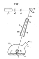
- FIG. 1 shows a highly simplified schematic illustration of a test arrangement for the contactless determination of defects D in non-structured areas F, in which a device E1 is used in the beam path Generation of a scanning light beam As, a widening optics Ao, a focusing optics Fo, a deflection device Ae and an aperture B are arranged in order to reduce the amount of scattered light.
- the scanning light beam As which is periodically moved back and forth in the plane of the drawing by the deflection device Ae in accordance with the double arrow Dpf, passes through a slit of a device E2 to be explained, onto the area F to be examined of a test specimen denoted by P.
- the test specimen P is moved in a direction perpendicular to the plane of the drawing, so that the surface F is scanned by the scanning light beam.
- the test specimen P can optionally also be moved with a meandering path. If the scanning light beam As occurs on defect-free areas of the area F, it leaves the device E2 again in the reflection direction through the slot through which it entered.
- the scanning light beam strikes a defect D, which can be a pore of the surface F, the inclusion of a foreign body, contamination of the surface or the like, the light is scattered and diffracted, the corresponding scattering lobe being denoted by Sk is.
- the light scattered and diffracted at the defect location is then at least partially collected by the device E2 on the light-sensitive surface of an optoelectronic receiver E, the output signal S of which indicates the defect D found.
- the device E1 for generating the scanning light beam As is in particular a laser, for example a HeCd laser, the beam of which in the Expanding optics Ao, for example, is expanded from an initial diameter of 1 mm to a diameter of 4 mm.
- the expanded laser beam is then focused onto the surface F by the focus optics Fo, the diameter of the beam at the point of impact being approximately 50 ⁇ m.
- the aperture B comprises two side walls labeled Sw and two end walls labeled Ew, the position and inclination of the two end walls Ew being matched to the maximum deflection of the scanning light beam As.
- the two side walls Sw are arranged shortly in front of or behind the deflection plane of the scanning light beam As lying in the plane of the drawing. Further details on the structure and the mode of operation of the diaphragm B will be explained later with reference to FIGS. 2 and 3 to 5.
- the device E2 for collecting the light deflected at the defect location is a hemisphere which is open at the bottom and which is arranged above the surface F of the test specimen P.
- the hemisphere is painted matt white on the inside, so that light scattered and diffracted from the defect D is often diffusely reflected and each surface element of the inner surface of the hemisphere is illuminated with approximately the same intensity.
- the light fluxes emanating from a defect D are detected and partially supplied to the light-sensitive surface of the optoelectronic receiver E, for example a photomultiplier, located in the region of the inner surface of the hemisphere.
- the device E2 which fulfill the desired collecting function are also possible. Deviating from the examination of the surface F shown in incident light, the examination can also be carried out in transmitted light, the Device E2 is then arranged in a corresponding manner on the underside of the test specimen P.
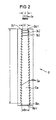
- FIG. 2 shows a side view of the panel B with the front end wall Ew removed.
- a sawtooth-shaped profile is also introduced on the inside, by which only additional diaphragm edges Bkz1 to Bkzn are indicated in FIG. 2.
- These additional diaphragm edges Bkz1 to Bkzn assigned to the reversal points of the scanning light beam As are offset in relation to the diaphragm edges Bk1 to Bkn in such a way that in the corner regions of the diaphragm B which is adjustably and adjustably screwed together from the two side walls Sw and the two end walls Ew, no mutual hindrance can occur.
- the two side walls Sw and the two end walls Ew are made of aluminum, the profiled inner surfaces each being anodized in matt black.
- the width b1 of the diaphragm gap formed by the first diaphragm edge Bk1 preferably corresponds to the diameter d of the scanning light beam As indicated by arrows and is 1 mm in the exemplary embodiment shown.
- the width bn of the aperture gap formed by the last aperture edge Bkn is 1.5 mm.
- Figure 3 shows the principle of operation of the aperture B, wherein only the first three diaphragm edges Bk1, Bk2 and Bk3 are indicated.
- the first diaphragm edge Bk1 forms a diaphragm gap of width b1, the light space of which is designated Lr1 and the shadow space of which is designated Sr1.
- the second diaphragm edge Bk2 forms a diaphragm gap of width b2, the light space of which is designated Lr2 and the shadow space of which is Sr2.
- the third diaphragm edge Bk3 forms a diaphragm gap of width b3, the light space of which is designated Lr3 and the shadow space of which is designated Sr3.
- the width b1 of the aperture gap formed by the first aperture edge Bk1 is dimensioned such that it is at least approximately equal to the diameter d of the scanning light beam As.
- the first diaphragm edge Bk1 then diffracts the light both into the shadow space Sr1 and into the light space Lr1.
- the second diaphragm edge Bk2 is now arranged in the shadow space Sr1 such that it cuts the first secondary maximum of the light diffracted by the first diaphragm edge Bk1 into the assigned shadow space Sr1.
- the second diaphragm edge Bk2 then bends the light back both into the assigned shadow space Sr2 and into the assigned light space Lr2.
- the third diaphragm edge Bk3 is then arranged in the shadow space Sr2 in such a way that it cuts the first secondary maximum of the light diffracted by the second diaphragm edge Bk2 into the assigned shadow space Sr2. It can be seen that the diffracted light is continuously reduced in the direction of the scanning light beam As and thus the halo of the scanning light beam As is reduced further and further.
- the intensity I of the scanning light beam As is entered over the beam cross section Sq before it enters the diaphragm B (see FIGS. 1 and 2).
- the resulting bell curve or Gaussian distribution curve is labeled Gk, while the unwanted stray light portion of the scanning light beam As is shown by curve branches St.
- the intensity I of the scanning light beam As after it emerges from the diaphragm B is plotted over the beam cross section Sq, the resulting curve being designated K.
- the typical bell curve Gk according to FIG. 4 is practically trimmed laterally due to the effect of the aperture B and the shading of the scattered light, and the resulting curve K approaches a rectangular shape R indicated by dash-dotted lines.
- the halo of the scanning light beam As is at least largely eliminated by the effect of the diaphragm B.
- the signal-to-noise ratio of the test arrangement shown in FIG. 1 is improved in such a way that even the smallest defects with dimensions in the submicron range can be reliably detected.
Abstract
Zur Ermittlung von Defekten (D) in nicht strukturierten Flächen (F) wird die zu untersuchende Fläche (F) mit einem Abtastlichtstrahl (As) abgescannt, wobei das von einem Defekt (d) gestreute und gebeugte Licht auf der lichtempfindlichen Fläche eines optoelektronischen Empfängers (E) gesammelt wird. Um auch Defekte (D) im Submikrometerbereich erfassen zu können, wird im Strahlengang des Abtastlichtstrahls (As) eine Blende (B) zur Reduzierung des Streulichtanteils angebracht, in welcher mindestens zwei Blendenkanten, vorzugsweise eine Vielzahl von Blendenkanten, so hintereinander angeordnet sind, daß sie jeweils nur den Schattenbereich der vorhergehenden Blendenkante erfassen. Eine derartige Prüfanordnung wird z. B. bei der Prüfung von noch nicht strukturierten Masken eingesetzt. 
Description
Die Erfindung betrifft eine Prüfanordnung zur berührungslosen Ermittlung von Defekten in nicht strukturierten Flächen nach dem Oberbegriff des Anspruchs 1.The invention relates to a test arrangement for the contactless determination of defects in non-structured areas according to the preamble of
Zum Auffinden von Defekten in nicht strukturierten Flächen wird die zu untersuchende Fläche eines Prüflings mit einem Laserstrahl abgescannt. Die hierzu erforderliche Relativbewegung zwischen Laserstrahl und Prüfling wird dabei meist in einer ersten Richtung durch einen im Strahlengang angeordneten Scanspiegel und in einer zur ersten Richtung senkrechten zweiten Richtung durch Verfahren des Prüflings erzeugt. Trifft der Laserstrahl auf eine Defektstelle, so wird das Licht gestreut bzw. gebeugt und kann dann im Auflicht bzw. im Durchlicht, von einem optoelektronischen Empfänger detektiert werden, welcher ein dem aufgefundenen Defekt entsprechendes Signal liefert. Um dem optoelektronischen Empfänger einen möglichst großen Teil des an einer Defektstelle abgelenkten Lichtes zuzuführen, wird dieses Licht zuvor in einer entsprechenden optischen Einrichtung gesammelt. Als optische Sammeleinrichtung wird dabei beispielsweise eine nach dem Prinzip der Ulbricht'schen Kugel wirkende Halbkugel verwendet, welche die einzelnen von einer Defektstelle ausgehenden Lichtströme integriert, d.h. über die Innenfläche der Halbkugel voll erfaßt. Neben der Kugelform können jedoch auch andere für optische Sammelelemente gebräuchliche Formen wie elliptische Hohlkörper, Ellipsoide, parabolförmige Hohlkörper oder Paraboloide und dergleichen verwendet werden.To find defects in unstructured areas, the area of a test object to be examined is scanned with a laser beam. The required relative movement between the laser beam and the test object is usually generated in a first direction by a scanning mirror arranged in the beam path and in a second direction perpendicular to the first direction by moving the test object. If the laser beam strikes a defect, the light is scattered or diffracted and can then be detected in incident light or transmitted light by an optoelectronic receiver which delivers a signal corresponding to the defect found. In order to supply the optoelectronic receiver with as much of the light as possible deflected at a defect location, this light is previously collected in a corresponding optical device. A hemisphere acting according to the principle of the Ulbricht sphere is used as the optical collecting device, for example, which integrates the individual light fluxes emanating from a defect location, ie fully detects it over the inner surface of the hemisphere. In addition to the spherical shape, however, other shapes customary for optical collecting elements, such as elliptical hollow bodies, ellipsoids, parabolic hollow bodies or paraboloids and the like, can also be used.
Bei den bekannten, häufig auch als Lasercanner bezeichneten Prüfanordnungen hat der als Abtastlichtstrahl verwendete Laserstrahl einem relativ großen Lichthof, der insbesondere auf Streulicht von Linsen, Spiegeloberflächen und vom Laser selbst zurückzuführen ist. Dieser Lichthof verursacht dann ein ungünstiges Signal-Rausch-Verhältnis, so daß kleinere Defekte nicht mehr zuverlässig ermittelt werden können. Bei der Prüfung von noch nicht strukturierten Masken für die Halbleitertechnik, von Compact-Disks für die Bild- und Tonspeicherung und von Magnetspeicherplatten kommt es jedoch gerade darauf an, in den Oberflächen oder in einzelnen Schichten auch kleinste Defekte mit Abmessungen im Submikrometerbereich zu erfassen.In the known test arrangements, which are often also referred to as laser scanners, the laser beam used as a scanning light beam has a relatively large halo, which is in particular due to scattered light from lenses, mirror surfaces and from the laser itself. This halo then causes an unfavorable signal-to-noise ratio, so that smaller defects can no longer be reliably determined. When testing masks for semiconductor technology that have not yet been structured, compact disks for image and sound storage and magnetic storage disks, it is important to detect even the smallest defects with dimensions in the submicrometer range in the surfaces or in individual layers.
Der Erfindung liegt die Aufgabe zugrunde, eine Prüfanordnung zur berührungslosen Ermittlung von Defekten in nicht strukturierten Flächen zu schaffen, mit welcher auch kleinste Defekte mit Abmessungen im Submikrometerbereich zuverlässig erkannt werden können.The invention has for its object to provide a test arrangement for the contactless determination of defects in non-structured areas, with which even the smallest defects with dimensions in the submicron range can be reliably detected.
Diese Aufgabe wird bei einer gattungsgemäßen Prüfanordnung durch die kennzeichnenden Merkmale des Anspruchs 1 gelöst.This object is achieved in a generic test arrangement by the characterizing features of
Der Erfindung liegt die Erkenntnis zugrunde, daß durch eine in den Strahlengang eingefügte Blende der Streulichtanteil des Abtastlichtstrahls so weit reduziert werden kann, daß aufgrund eines entsprechend verbesserten Signal-Rausch-Verhältnisses auch kleinste Defekte im Submikrometerbereich zuverlässig erfaßt werden können. Voraussetzung für eine derartige Wirkung der Blende ist dabei, daß sie mindestens zwei, vorzugsweise eine Vielzahl, hintereinander angeordneter Blendenkanten aufweist, wobei jede nachgeordnete Blendenkante das von der vorausgehenden Blendenkante in den Schattenraum gebeugte Licht zumindest teilweise erfaßt. Bei einer derartigen Anordnung wird also in Richtung des Abtastlichtstrahls gesehen mit jeder Blendenkante das gebeugte Licht weiter reduziert, wobei sich das Strahlprofil des Abtastlichtstrahls in Richtung auf eine Rechteckform verändert.The invention is based on the finding that, by means of an aperture inserted into the beam path, the scattered light component of the scanning light beam can be reduced to such an extent that even the smallest defects in the submicron range can be reliably detected due to a correspondingly improved signal-to-noise ratio. A prerequisite for such an effect of the diaphragm is that it has at least two, preferably a large number of diaphragm edges arranged one behind the other, each subordinate diaphragm edge diffracting from the preceding diaphragm edge into the shadow space Light at least partially detected. With such an arrangement, the diffracted light is thus further reduced with each diaphragm edge when viewed in the direction of the scanning light beam, the beam profile of the scanning light beam changing in the direction of a rectangular shape.
Gemäß einer bevorzugten weiteren Ausgestaltung der Erfindung sind die Blendenkanten derart hintereinander angeordnet, daß jede nachgeordnete Blendenkante das erste Nebenmaximum des von der vorausgehenden Blendenkante in den zugeordnenten Schattenraum gebeugten Lichtes anschneidet. Druch einen derartigen Ausschnitt der Nebenmaxima wird ein besonders großer Anteil des Streulichts unwirksam gemacht.According to a preferred further embodiment of the invention, the diaphragm edges are arranged one behind the other in such a way that each subordinate diaphragm edge cuts the first secondary maximum of the light diffracted from the preceding diaphragm edge into the associated shadow space. Such a section of the secondary maxima makes a particularly large proportion of the scattered light ineffective.
Die Blendenkanten sind vorzugsweise als scharfe Schneiden ausgebildet, wodurch die Reflexionsoberflächen der Blendenkanten und der Anteil des an ihnen reflektierten Streulichts verringert werden. Außerdem ist es auch vorteilhaft, wenn die zwischen den Blendenkanten liegenden Bereiche der Blende eine lichtabsorbierende Oberfläche aufweisen, so daß das in den Schattenraum und in den Lichtraum gebeugte Licht absorbiert und damit unwirksam gemacht werden kann.The diaphragm edges are preferably designed as sharp cutting edges, as a result of which the reflection surfaces of the diaphragm edges and the proportion of the scattered light reflected on them are reduced. In addition, it is also advantageous if the regions of the diaphragm lying between the diaphragm edges have a light-absorbing surface, so that the light diffracted into the shadow space and into the light space can be absorbed and thus rendered ineffective.
Bei Prüfanordnungen, bei welchen im Strahlengang des Abtastlichtstrahls eine Ablenkeinrichtung angeordnet ist, wird die Blende in Richtung des Abtastlichtstrahls gesehen zweckmäßigerweise nach der Ablenkeinrichtung angeordnet. Die Blende kann dann auch das von der Ablenkeinrichtung, beispielsweise einem Scanspiegel, erzeugte Streulicht erfassen und reduzieren bzw. unwirksam machen.In test arrangements in which a deflection device is arranged in the beam path of the scanning light beam, the diaphragm is expediently arranged downstream of the deflection device when viewed in the direction of the scanning light beam. The diaphragm can then also detect and reduce the scattered light generated by the deflection device, for example a scanning mirror, or render it ineffective.
Bei Verwendung einer Ablenkeinrichtung für den Abtastlichtstrahl werden die Blendenkanten dann vorzugsweise parallel zur Ablenkebene des Abtastlichtstrahls ausgerichtet, so daß der Durchtritt des für die Abtastung erwünschten Lichtanteils nicht behindert wird. Den Umkehrprodukten des Abtastlichtstrahls können dann zusätzliche Blendenkanten der Blende zugeordnet werden, so daß der Streulichtanteil auch im Bereich der Umkehrpunkte reduziert werden kann.When using a deflection device for the scanning light beam, the diaphragm edges are then preferred aligned parallel to the deflection plane of the scanning light beam, so that the passage of the light portion desired for the scanning is not hindered. Additional diaphragm edges of the diaphragm can then be assigned to the reversal products of the scanning light beam, so that the proportion of scattered light can also be reduced in the region of the reversal points.
Gemäß einer besonders bevorzugten Ausgestaltung der Erfindung sind die Blendenkanten durch ein sägezahnförmiges Profil auf der Innenseite von einander gegenüberliegenden Seitenwändern der Blende gebildet. Hierdurch wird die Herstellung der Blende erheblich vereinfacht und eine fixe Raltivlage der Blendenkanten einer Seitenwand gewährleistet. Außerdem kann durch das sägezahnförmige Profil eine Vielzahl von Blendenkanten auf einem engen Raum untergebracht werden. Diese Vorteile ergeben sich dann auch, wenn die zusätzlichen Blendenkanten durch ein sägezahnförmiges Profil auf der Innenseite von einander gegenüberliegenden und gegensinnig geneigten Endwänden der Blende gebildet sind. Vorzugsweise sind die Blendenkanten dann versetzt zu den zusätzlichen Blendenkanten angeordnet, so daß die Blendenkanten und die zusätzlichen Blendenkanten in den Eckbereichen der Blende ohne sich zu stören ineinander eingreifen können. Sind die beiden Seitenwände und die beiden Endwände der Blende dann verstell- und justierbar miteinander verbunden, so kann durch eine entsprechende Justierung die Wirkung der Blende auf einfache Weise optimiert werden.According to a particularly preferred embodiment of the invention, the panel edges are formed by a sawtooth-shaped profile on the inside of opposite side walls of the panel. This considerably simplifies the manufacture of the diaphragm and ensures a fixed position of the diaphragm edges of a side wall. In addition, the sawtooth-shaped profile can accommodate a large number of diaphragm edges in a narrow space. These advantages also arise if the additional diaphragm edges are formed by a sawtooth-shaped profile on the inside of opposing and oppositely inclined end walls of the diaphragm. The diaphragm edges are then preferably offset from the additional diaphragm edges, so that the diaphragm edges and the additional diaphragm edges can engage in one another without interfering in the corner regions of the diaphragm. If the two side walls and the two end walls of the screen are connected to one another in an adjustable and adjustable manner, the effect of the screen can be optimized in a simple manner by appropriate adjustment.
Im Hinblick auf eine möglichst effektive Reduzierung des Streulichtanteils ist es auch besonders vorteilhaft, wenn die Breite des durch die erste Blendenkante gebildeten Blendenspaltes zumindest annähernd dem Durchmesser des Abtastlichtstrahls entspricht.In order to reduce the amount of scattered light as effectively as possible, it is also particularly advantageous if the width of the aperture gap formed by the first aperture edge corresponds at least approximately to the diameter of the scanning light beam.
Die von den Blendenkanten in den Lichtraum gebeugten Strahlen können durch die Blende hindurchtreten, wenn sie steiler sind als die Diagonale zwischen der ersten und der letzten Blendenkante. Der Diagonalwinkel sollte daher möglichst klein gehalten werden. Dies wird durch entsprechende Bemessungen erreicht, bei welchen der Abstand zwischen der ersten Blendenkante und der letzten Blendenkante zumindest dem 10-fachen vorzugsweise etwa dem 100-fachen bis 200-fachen, Wert des Durchmessers des Abtastlichtstrahls entspricht.The rays diffracted into the light space by the diaphragm edges can pass through the diaphragm if they are steeper than the diagonal between the first and the last diaphragm edge. The diagonal angle should therefore be kept as small as possible. This is achieved by appropriate dimensions, in which the distance between the first diaphragm edge and the last diaphragm edge corresponds to at least 10 times, preferably approximately 100 to 200 times, the value of the diameter of the scanning light beam.
Ein Ausführungsbeispiel der Erfindung ist in der Zeichnung dargestellt und wird im folgenden näher beschrieben.An embodiment of the invention is shown in the drawing and will be described in more detail below.
Es zeigen
Figur 1 eine Prüfanordnung zur berührungslosen Ermittlung von Defekten in nicht strukturierten Flächen in stark vereinfachter schematischer Darstellung,Figur 2 Einzelheiten der in der Prüfanordnung nachFigur 1 eingesetzten Blende zur Reduzierung des Streulichtanteils,Figur 3 das Wirkungsprinzip der in denFiguren 1 und 2 dargestellten Blende zur Reduzierung des Streulichtanteils,Figur 4 das Strahlprofil des Abtastlichtstrahls vor dem Eintritt in die Blende zur Reudzierung des Streulichtanteils und- Figur 5 das Strahlprofil des Abtastlichtstrahls nach dem Durchtritt durch die Blende zur Reduzierung des Streulichtanteils.
- FIG. 1 shows a test arrangement for the contactless determination of defects in non-structured areas in a highly simplified schematic representation,
- FIG. 2 details of the diaphragm used in the test arrangement according to FIG. 1 to reduce the proportion of scattered light,
- FIG. 3 shows the principle of operation of the diaphragm shown in FIGS. 1 and 2 for reducing the proportion of scattered light,
- FIG. 4 shows the beam profile of the scanning light beam before it enters the diaphragm for the reudation of the scattered light component and
- Figure 5 shows the beam profile of the scanning light beam after passing through the aperture to reduce the amount of stray light.
Figur 1 zeigt in stark vereinfachter schematischer Darstellung eine Prüfanordnung zur berührungslosen Ermittlung von Defekten D in nicht strukturierten Flächen F, bei welcher im Strahlengang einer Einrichtung E1 zur Erzeugung eines Abtastlichtstrahls As nacheinander eine Aufweitoptik Ao, eine Fokusoptik Fo, eine Ablenkeinrichtung Ae und eine Blende B zur Reduzierung des Streulichtanteils angeordnet sind. Nach dem Durchtritt durch die Blende B gelangt der durch die Ablenkeinrichtung Ae entsprechend dem Doppelpfeil Dpf in der Zeichnungsebene periodische hin- und herbewegte Abtastlichtstrahl As durch einen Schlitz einer noch zu erläuternden Einrichtung E2 hindruch auf die zu untersuchende Fläche F eines mit P bezeichneten Prüflings. Neben der bereits erwähnten Auslenkung des Abtastlichtstrahls wird der Prüfling P in einer zur Zeichnungsebene senkrechten Richtung verfahren, so daß die Fläche F durch den Abtastlichtstrahl abgescannt wird. Um den abzutastenden Bereich der Fläche F, bei welcher es sich auch um eine Zwischenschicht handeln kann, zu vergrößern, kann der Prüfling P gegebenenfalls auch mit einer mäanderförmigen Bahn verfahren werden. Tritt der Abtastlichtstrahl As auf fehlerfreie Bereiche der Fläche F, so verläßt er in Reflexionsrichtung die Einrichtung E2 wieder durch den Schlitz, durch welchen er eingetreten ist. Trifft der Abtastlichtstrahl dagegen auf einen Defekt D, bei welchen es sich um eine Pore der Fläche F, um den Einschlußeines Fremdkörpers, um eine Verunreinigung der Oberfläche oder dergleichen handeln kann, so wird das Licht gestreut und gebeugt, wobei die entsprechende Streukeule mit Sk bezeichnet ist. Das an der Defektstelle gestreute und gebeugte Licht wird dann durch die Einrichtung E2 auf der lichtempfindlichen Fläche eines optoelektronischen Empfängers E zumindest teilweise gesammelt, dessen Ausgangssignal S den aufgefundenen Defekt D anzeigt.FIG. 1 shows a highly simplified schematic illustration of a test arrangement for the contactless determination of defects D in non-structured areas F, in which a device E1 is used in the beam path Generation of a scanning light beam As, a widening optics Ao, a focusing optics Fo, a deflection device Ae and an aperture B are arranged in order to reduce the amount of scattered light. After passing through the aperture B, the scanning light beam As, which is periodically moved back and forth in the plane of the drawing by the deflection device Ae in accordance with the double arrow Dpf, passes through a slit of a device E2 to be explained, onto the area F to be examined of a test specimen denoted by P. In addition to the deflection of the scanning light beam already mentioned, the test specimen P is moved in a direction perpendicular to the plane of the drawing, so that the surface F is scanned by the scanning light beam. In order to enlarge the area of the area F to be scanned, which can also be an intermediate layer, the test specimen P can optionally also be moved with a meandering path. If the scanning light beam As occurs on defect-free areas of the area F, it leaves the device E2 again in the reflection direction through the slot through which it entered. If, on the other hand, the scanning light beam strikes a defect D, which can be a pore of the surface F, the inclusion of a foreign body, contamination of the surface or the like, the light is scattered and diffracted, the corresponding scattering lobe being denoted by Sk is. The light scattered and diffracted at the defect location is then at least partially collected by the device E2 on the light-sensitive surface of an optoelectronic receiver E, the output signal S of which indicates the defect D found.
Bei der Einrichtung E1 zur Erzeugung des Abtastlichtstrahls As handlet es sich insbesondere um einen Laser, beispielsweise um einen HeCd-Laser, dessen Strahl in der Aufweitoptik Ao beispielsweise von einem Ausgangsdurchmesser von 1 mm auf einen Durchmesser von 4 mm aufgeweitet wird. Der aufgeweitete Laserstrahl wird dann durch die Fokusoptik Fo auf die Fläche F fokussiert, wobei der Durchmesser des Strahls an der Auftreffstelle etwa 50 µm beträgt.The device E1 for generating the scanning light beam As is in particular a laser, for example a HeCd laser, the beam of which in the Expanding optics Ao, for example, is expanded from an initial diameter of 1 mm to a diameter of 4 mm. The expanded laser beam is then focused onto the surface F by the focus optics Fo, the diameter of the beam at the point of impact being approximately 50 μm.
Die Blende B umfaßt zwei mit Sw bezeichneten Seitenwände und zwei mit Ew bezeichnete Endwände, wobei Lage und Neigung der beiden Endwände Ew auf die maximale Auslenkung des Abtastlichtstrahls As abgestimmt sind. Die beiden Seitenwände Sw sind kurz vor bzw. hinter der in der Zeichungsebene liegenden Ablenkebene des Abtastlichtstrahls As angeordnet. Weitere Einzelheiten über den Aufbau und die Wirkungsweise der Blende B werden an späterer Stelle anhand der Figuren 2 bzw. 3 bis 5 erläutert.The aperture B comprises two side walls labeled Sw and two end walls labeled Ew, the position and inclination of the two end walls Ew being matched to the maximum deflection of the scanning light beam As. The two side walls Sw are arranged shortly in front of or behind the deflection plane of the scanning light beam As lying in the plane of the drawing. Further details on the structure and the mode of operation of the diaphragm B will be explained later with reference to FIGS. 2 and 3 to 5.
Bei der Einrichtung E2 zum Sammeln des an der Defektstelle abgelenkten Lichtes handelt es sich um eine nach unten offene Halbkugel, welche über der Fläche F des Prüflings P angeordnet wird. Wie bei einem Kugel- oder Integralphometer nach Ulbricht ist die Halbkugel innen mattweiß angestrichen, so daß an dem Defekt D gestreute und gebeugte Licht vielfach diffus reflektiert und jedes Flächenelement der Innenfläche der Halbkugel annähernd gleich stark beleuchtet wird. Auf diese Weise werden die von einem Defekt D ausgehenden Lichtströme erfaßt und der im Bereich der Innenfläche der Halbkugel liegenden lichtempfindlichen Fläche des beispielsweise als Photomultiplier ausgebildeten optoelektronischen Empfängers E teilweise zugeführt. Andere Formen der Einrichtung E2, welche die erwünschte Sammelfunktion erfüllen, sind ebenfalls möglich. Abweichend von der dargestellten Untersuchung der Fläche F im Auflicht kann die Untersuchung auch im Durchlicht vorgenommen werden, wobei die Einrichtung E2 dann in entsprechender Weise auf der Unterseite des Prüflings P angeordnet wird.The device E2 for collecting the light deflected at the defect location is a hemisphere which is open at the bottom and which is arranged above the surface F of the test specimen P. As with a Ulbricht spherical or integral photometer, the hemisphere is painted matt white on the inside, so that light scattered and diffracted from the defect D is often diffusely reflected and each surface element of the inner surface of the hemisphere is illuminated with approximately the same intensity. In this way, the light fluxes emanating from a defect D are detected and partially supplied to the light-sensitive surface of the optoelectronic receiver E, for example a photomultiplier, located in the region of the inner surface of the hemisphere. Other forms of the device E2 which fulfill the desired collecting function are also possible. Deviating from the examination of the surface F shown in incident light, the examination can also be carried out in transmitted light, the Device E2 is then arranged in a corresponding manner on the underside of the test specimen P.
Die Figur 2 zeigt eine seitliche Ansicht auf die Blende B mit abgenommener vorderer Endwand Ew. Die Innenseiten der Seitenwände Sw sind mit einem sägezahnförmigen Profil versehen, durch welches jeweils beispielsweise auf gleicher Höhe einander gegenüberliegende Blendenkanten Bk1, Bk2 bis Bkn gebildet werden, wobei im dargestellten Ausführungsbeispiel n = 30 ist. Die senkrecht zur Zeichnungsebene nach hinten verlaufenden Blendenkanten Bk1 bis Bkn bilden jeweils Blendenspalte, deren Breite b1 bis bn in Richtung des Abtastlichtstrahls As zunimmt. In die beiden schräg gegeneinander geneigten Endwände Ew ist innen ebenfalls ein sägezahnförmiges Profil eingebracht, durch welches in Figur 2 nur angedeutete zusätzliche Blendenkanten Bkz1 bis Bkzn gebildet werden. Diese den Umkehrpunkten des Abtastlichtstrahls As zugeordneten zusätzlichen Blendenkanten Bkz1 bis Bkzn sind gegenüber den Blendenkanten Bk1 bis Bkn so versetzt, daß in den Eckbereichen der aus den beiden Seitenwänden Sw und den beiden Endwänden Ew verstell- und justierbar zusammengeschraubten Blende B keine gegenseitige Behinderung auftreten kann. Die beiden Seitenwände Sw und die beiden Endwände Ew bestehen aus Aluminium, wobei die profilierten Innenflächen jeweils mattschwarz eloxiert sind.FIG. 2 shows a side view of the panel B with the front end wall Ew removed. The inner sides of the side walls Sw are provided with a sawtooth-shaped profile, by means of which diaphragm edges Bk1, Bk2 to Bkn, which are opposite one another, for example, are formed at the same height, n = 30 in the exemplary embodiment shown. The diaphragm edges Bk1 to Bkn, which run perpendicular to the plane of the drawing, each form diaphragm gaps whose width b1 to bn increases in the direction of the scanning light beam As. In the two obliquely inclined end walls Ew, a sawtooth-shaped profile is also introduced on the inside, by which only additional diaphragm edges Bkz1 to Bkzn are indicated in FIG. 2. These additional diaphragm edges Bkz1 to Bkzn assigned to the reversal points of the scanning light beam As are offset in relation to the diaphragm edges Bk1 to Bkn in such a way that in the corner regions of the diaphragm B which is adjustably and adjustably screwed together from the two side walls Sw and the two end walls Ew, no mutual hindrance can occur. The two side walls Sw and the two end walls Ew are made of aluminum, the profiled inner surfaces each being anodized in matt black.
Die Breite b1 des durch die erste Blendenkante Bk1 gebildeten Blendenspaltes entspricht vorzugsweise dem Durchmesser d des durch Pfeile angedeuteten Abtastlichtstrahls As und beträgt im dargestellten Ausführungsbeispiel 1 mm. Die Breite bn des durch die letzte Blendenkante Bkn gebildeten Blendenspaltes beträgt demgegenüber 1,5 mm.The width b1 of the diaphragm gap formed by the first diaphragm edge Bk1 preferably corresponds to the diameter d of the scanning light beam As indicated by arrows and is 1 mm in the exemplary embodiment shown. In contrast, the width bn of the aperture gap formed by the last aperture edge Bkn is 1.5 mm.
Figur 3 zeigt das Wirkungsprinzip der Blende B, wobei lediglich die ersten drei Blendenkanten Bk1, Bk2 und Bk3 angedeutet sind. Die erste Blendenkante Bk1 bildet einen Blendenspalt der Breite b1, dessen Lichtraum mit Lr1 und dessen Schattenraum mit Sr1 bezeichnet sind. Die zweite Blendenkante Bk2 bildet einen Blendenspalt der Breite b2, dessen Lichtraum mit Lr2 und dessen Schattenraum mit Sr2 bezeichnet sind. Die dritte Blendenkante Bk3 bildet einen Blendenspalt der Breite b3, dessen Lichtraum mit Lr3 und dessen Schattenraum mit Sr3 bezeichnet sind.Figure 3 shows the principle of operation of the aperture B, wherein only the first three diaphragm edges Bk1, Bk2 and Bk3 are indicated. The first diaphragm edge Bk1 forms a diaphragm gap of width b1, the light space of which is designated Lr1 and the shadow space of which is designated Sr1. The second diaphragm edge Bk2 forms a diaphragm gap of width b2, the light space of which is designated Lr2 and the shadow space of which is Sr2. The third diaphragm edge Bk3 forms a diaphragm gap of width b3, the light space of which is designated Lr3 and the shadow space of which is designated Sr3.
Die Breite b1 des durch die erste Blendenkante Bk1 gebildeten Blendenspaltes ist derart bemessen, daß sie zumindest annähernd gleich dem Durchmesser d des Abtastlichtstrahls As ist. Die erste Blendenkante Bk1 beugt dann das Licht sowohl in den Schattenraum Sr1 als auch in den Lichtraum Lr1. Die zweite Blendenkante Bk2 ist nun derart im Schattenraum Sr1 angeordnet, daß sie das erste Nebenmaximum des von der ersten Blendenkante Bk1 in den zugeordneten Schattenraum Sr1 gebeugten Lichtes anschneidet. Die zweite Blendenkante Bk2 beugt dann das Licht wieder sowohl in den zugeordneten Schattenraum Sr2 als auch in den zugeordneten Lichtraum Lr2. Entsprechend dem vorstehend aufgezeigten Wirkungsprinzip ist dann die dritte Blendenkante Bk3 derart im Schattenraum Sr2 angeordnet, daß sie das erste Nebenmaximum des von der zweiten Blendenkante Bk2 in den zugeordneten Schattenraum Sr2 gebeugten Lichts anschneidet. Es ist ersichtlich, daß das gebeugte Licht in Richtung des Abtastlichtstrahls As gesehen laufend reduziert wird und somit der Lichthof des Abtastlichtstrahls As immer weiter reduziert wird.The width b1 of the aperture gap formed by the first aperture edge Bk1 is dimensioned such that it is at least approximately equal to the diameter d of the scanning light beam As. The first diaphragm edge Bk1 then diffracts the light both into the shadow space Sr1 and into the light space Lr1. The second diaphragm edge Bk2 is now arranged in the shadow space Sr1 such that it cuts the first secondary maximum of the light diffracted by the first diaphragm edge Bk1 into the assigned shadow space Sr1. The second diaphragm edge Bk2 then bends the light back both into the assigned shadow space Sr2 and into the assigned light space Lr2. In accordance with the principle of operation shown above, the third diaphragm edge Bk3 is then arranged in the shadow space Sr2 in such a way that it cuts the first secondary maximum of the light diffracted by the second diaphragm edge Bk2 into the assigned shadow space Sr2. It can be seen that the diffracted light is continuously reduced in the direction of the scanning light beam As and thus the halo of the scanning light beam As is reduced further and further.
In Figur 4 ist die Intensität I des Abtastlichtstrahls As vor dem Eintritt in die Blende B (vgl. Figuren 1 und 2) über dem Strahlquerschnitt Sq aufgetragen. Die resultierende Glockenkurve oder Gauß-Verteilungs-Kurve ist mit Gk bezeichnet, während der unerwünschte Streulicht anteil des Abtastlichtstrahls As durch Kurvenzweige St aufgezeigt ist. Bei der Intensität I = 1/e² Imax beträgt der Strahlquerschnitt Sq = π· d²/4, wobei d der bereits erwähnte Durchmesser des Abtastlichtstrahls ist.In FIG. 4, the intensity I of the scanning light beam As is entered over the beam cross section Sq before it enters the diaphragm B (see FIGS. 1 and 2). The resulting bell curve or Gaussian distribution curve is labeled Gk, while the unwanted stray light portion of the scanning light beam As is shown by curve branches St. With the intensity I = 1 / e² Imax, the beam cross section is Sq = π · d² / 4, where d is the diameter of the scanning light beam already mentioned.
In Figur 5 ist die Intensität I des Abtastlichtstrahls As nach dem Austritt aus der Blende B über dem Strahlquerschnitt Sq aufgetragen, wobei die resultierende Kurve mit K bezeichnet ist. Es ist ersichtlich, daß durch die Wirkung der Blende B und die Abschattung des Streulichts die typische Glockenkurve Gk gemäß Figur 4 praktisch seitlich beschnitten wird und die resultierende Kurve K sich einer strichpunktiert angedeuteten Rechteckform R nähert. Der Lichthof des Abtastlichtstrahls As wird durch die Wirkung der Blende B zumindest weitgehend beseitigt. Als Folge davon wird das Signal-Rausch-Verhältnis der in Figur 1 aufgezeigten Prüfanordnung derart verbessert, daß auch kleinste Defekte mit Abmessungen im Submikrometerbereich zuverlässig erfaßt werden können.In FIG. 5, the intensity I of the scanning light beam As after it emerges from the diaphragm B is plotted over the beam cross section Sq, the resulting curve being designated K. It can be seen that the typical bell curve Gk according to FIG. 4 is practically trimmed laterally due to the effect of the aperture B and the shading of the scattered light, and the resulting curve K approaches a rectangular shape R indicated by dash-dotted lines. The halo of the scanning light beam As is at least largely eliminated by the effect of the diaphragm B. As a result, the signal-to-noise ratio of the test arrangement shown in FIG. 1 is improved in such a way that even the smallest defects with dimensions in the submicron range can be reliably detected.
- Ac AblenkeinrichtungAc deflector
- Ao AufweitoptikAo widening optics
- As AbtastlichtstrahlAs scanning beam
- B BlendeB aperture
- Bk1, Bk2, Bk3...Bkn BlendenkanteBk1, Bk2, Bk3 ... Bkn aperture edge
- Bkz1...Bkzn zusätzliche BlendenkanteBkz1 ... Bkzn additional aperture edge
- D DefektD defect
- Dpf DoppelpfeilDpf double arrow
- E optoelektronischer EmpfängerE optoelectronic receiver
- E1 Einrichtung zur Erzeugung eines AbtastlichtstrahlsE1 Device for generating a scanning light beam
- E2 Einrichtung zum Sammeln des an einer Defektstelle abgelenkten LichtsE2 Device for collecting the light deflected at a defect location
- Ew Endwand der BlendeEw end wall of the panel
- F zu untersuchende FlächeF area to be examined
- Fo FokusoptikFo focus optics
- Gk GlockenkurveGk bell curve
- I Intensität des AbtastlichtstrahlsI intensity of the scanning light beam
- K KurveK curve
- Lr1, Lr2, Lr3 LichtraumLr1, Lr2, Lr3 clearance
- P PrüflingP DUT
- R RechteckformR rectangular shape
- S AusgangssignalS output signal
- Sk StrahlkeuleSk beam
- Sg StrahlquerschnittSg beam cross section
- Sr1, Sr2, Sr3 SchattenraumSr1, Sr2, Sr3 shadow space
- St KurvenzweigSt curve branch
- Sw Seitenwand der BlendeSw side panel of the bezel
- bl, b2, b3...bn Breite eines Blendenspaltsbl, b2, b3 ... bn Width of an aperture gap
- d Durchmesser des Abtastlichtstrahlsd diameter of the scanning light beam
Claims (15)
- einer Einrichtung zur Erzeugung eines Abtastlicht strahls
, - einer Einrichtung zum Sammeln des an einer Defekt stelle abgelenkten Lichtes und mit
- einem optoelektronischen Empfänger zur Detektion des gesammelten Lichts,
dadurch gekennzeichnet, daß im Strahlengang des Abtastlichtstrahls (As) eine Blende (B) zur Reduzierung des Streulichtanteils angebracht ist, in welcher mindestens zwei Blendenkanten (Bk1, Bk2) derart hintereinander angeordnet sind, daß jede nachgeordnete Blendenkante (Bk2) das von der vorausgehenden Blendenkante (Bk1) in den Schattenraum gebeugte Licht zumindest teilweise erfaßt.1. Test arrangement for the contactless determination of defects in non-structured areas, with
- A device for generating a scanning light beam
, - A device for collecting the light deflected at a defect and with
an optoelectronic receiver for detecting the collected light,
characterized in that in the beam path of the scanning light beam (As) there is a diaphragm (B) for reducing the proportion of scattered light, in which at least two diaphragm edges (Bk1, Bk2) are arranged one behind the other such that each subordinate diaphragm edge (Bk2) is that of the preceding diaphragm edge (Bk1) at least partially detected light diffracted into the shadow space.
Applications Claiming Priority (2)
| Application Number | Priority Date | Filing Date | Title |
|---|---|---|---|
| DE3532117 | 1985-09-09 | ||
| DE3532117 | 1985-09-09 |
Publications (2)
| Publication Number | Publication Date |
|---|---|
| EP0218865A1 true EP0218865A1 (en) | 1987-04-22 |
| EP0218865B1 EP0218865B1 (en) | 1989-12-27 |
Family
ID=6280467
Family Applications (1)
| Application Number | Title | Priority Date | Filing Date |
|---|---|---|---|
| EP86111838A Expired EP0218865B1 (en) | 1985-09-09 | 1986-08-27 | Test arrangement for the contactless ascertainment of flows in non-structured surfaces |
Country Status (3)
| Country | Link |
|---|---|
| US (1) | US4768878A (en) |
| EP (1) | EP0218865B1 (en) |
| DE (1) | DE3667855D1 (en) |
Cited By (2)
| Publication number | Priority date | Publication date | Assignee | Title |
|---|---|---|---|---|
| EP0408337A1 (en) * | 1989-07-13 | 1991-01-16 | De La Rue Systems Limited | Sheet inspection method and apparatus |
| FR2681133A1 (en) * | 1991-09-11 | 1993-03-12 | Languedoc Verrerie | LIGHT EMITTING OR ABSORBING DEVICE FOR THE CONTACTLESS CONTROL OF OBJECTS. |
Families Citing this family (6)
| Publication number | Priority date | Publication date | Assignee | Title |
|---|---|---|---|---|
| JP3142852B2 (en) * | 1990-02-20 | 2001-03-07 | 株式会社日立製作所 | Surface defect inspection equipment |
| US5155777A (en) * | 1991-06-26 | 1992-10-13 | International Business Machines Corporation | Scattered light blocking layer for optoelectronic receivers |
| US5309339A (en) * | 1992-06-24 | 1994-05-03 | The Schepens Eye Research Institute, Inc. | Concentrator for laser light |
| JP2800587B2 (en) * | 1992-10-05 | 1998-09-21 | 松下電器産業株式会社 | Foreign matter inspection device and foreign matter inspection method |
| US5444265A (en) * | 1993-02-23 | 1995-08-22 | Lsi Logic Corporation | Method and apparatus for detecting defective semiconductor wafers during fabrication thereof |
| DE10319543B4 (en) * | 2003-04-30 | 2011-03-03 | Byk-Gardner Gmbh | Apparatus and method for determining surface properties |
Citations (4)
| Publication number | Priority date | Publication date | Assignee | Title |
|---|---|---|---|---|
| US3917414A (en) * | 1973-10-11 | 1975-11-04 | Geisco Associates | Optical inspection system |
| FR2477288A1 (en) * | 1980-03-03 | 1981-09-04 | Vidal Bernard | Light trap with angular discrimination - has hollow housing with internal diaphragms and coaxial openings with light absorbent coating |
| US4378159A (en) * | 1981-03-30 | 1983-03-29 | Tencor Instruments | Scanning contaminant and defect detector |
| EP0146005B1 (en) * | 1983-11-26 | 1991-08-28 | Kabushiki Kaisha Toshiba | Surface defect inspecting apparatus |
Family Cites Families (5)
| Publication number | Priority date | Publication date | Assignee | Title |
|---|---|---|---|---|
| US2422273A (en) * | 1942-11-28 | 1947-06-17 | Brown Instr Co | Lens type radiation pyrometer |
| DE1473681A1 (en) * | 1965-11-17 | 1969-02-06 | Agfa Gevaert Ag | Procedure for optical troubleshooting, especially on large-area materials |
| CH592933A5 (en) * | 1976-04-05 | 1977-11-15 | Cerberus Ag | |
| JPS59208408A (en) * | 1983-05-13 | 1984-11-26 | Toshiba Corp | Method and device for inspecting surface |
| US4601576A (en) * | 1983-12-09 | 1986-07-22 | Tencor Instruments | Light collector for optical contaminant and flaw detector |
-
1986
- 1986-08-27 EP EP86111838A patent/EP0218865B1/en not_active Expired
- 1986-08-27 DE DE8686111838T patent/DE3667855D1/en not_active Expired - Fee Related
- 1986-09-09 US US06/905,186 patent/US4768878A/en not_active Expired - Fee Related
Patent Citations (4)
| Publication number | Priority date | Publication date | Assignee | Title |
|---|---|---|---|---|
| US3917414A (en) * | 1973-10-11 | 1975-11-04 | Geisco Associates | Optical inspection system |
| FR2477288A1 (en) * | 1980-03-03 | 1981-09-04 | Vidal Bernard | Light trap with angular discrimination - has hollow housing with internal diaphragms and coaxial openings with light absorbent coating |
| US4378159A (en) * | 1981-03-30 | 1983-03-29 | Tencor Instruments | Scanning contaminant and defect detector |
| EP0146005B1 (en) * | 1983-11-26 | 1991-08-28 | Kabushiki Kaisha Toshiba | Surface defect inspecting apparatus |
Cited By (5)
| Publication number | Priority date | Publication date | Assignee | Title |
|---|---|---|---|---|
| EP0408337A1 (en) * | 1989-07-13 | 1991-01-16 | De La Rue Systems Limited | Sheet inspection method and apparatus |
| US5084628A (en) * | 1989-07-13 | 1992-01-28 | De La Rue Systems Ltd. | Sheet inspection method and apparatus having retroreflecting means |
| FR2681133A1 (en) * | 1991-09-11 | 1993-03-12 | Languedoc Verrerie | LIGHT EMITTING OR ABSORBING DEVICE FOR THE CONTACTLESS CONTROL OF OBJECTS. |
| EP0533534A1 (en) * | 1991-09-11 | 1993-03-24 | Verrerie Du Languedoc Et Cie. | Device for absorbing or emitting light for contactless testing of objects |
| US5258611A (en) * | 1991-09-11 | 1993-11-02 | Verreries Du Languedoc | Light emission or absorption device for the contactless inspection of articles having a plurality of light sources and an elongate light guide |
Also Published As
| Publication number | Publication date |
|---|---|
| EP0218865B1 (en) | 1989-12-27 |
| DE3667855D1 (en) | 1990-02-01 |
| US4768878A (en) | 1988-09-06 |
Similar Documents
| Publication | Publication Date | Title |
|---|---|---|
| DE19960653B4 (en) | Method and device for the detection or orientation of edges | |
| DE2436110C3 (en) | Device for the detection of manufacturing defects in a moving material web | |
| EP2411787B1 (en) | Apparatus for determining particle sizes | |
| DE3913228C2 (en) | Diffuse reflection spectroscopy system and method for obtaining a diffuse reflection spectrum | |
| DE3926349C2 (en) | ||
| DE3309584A1 (en) | OPTICAL INSPECTION SYSTEM | |
| DE3034903A1 (en) | SYSTEM FOR DETECTING DEFECTS | |
| DE2620091A1 (en) | MEASURING SYSTEM FOR DETERMINING THE CONTOUR OF THE SURFACE OF AN OBJECT | |
| DE3303140A1 (en) | INFRARED SPECTROMETER | |
| DE2428123A1 (en) | ARRANGEMENT FOR DETECTION OF DEFECTS BY SCANNING BY A LASER BEAM | |
| DE4434699C2 (en) | Arrangement for checking transparent or reflective objects | |
| EP0218865B1 (en) | Test arrangement for the contactless ascertainment of flows in non-structured surfaces | |
| DE3409657A1 (en) | Dark-field illumination system for microscopes | |
| DE2550814A1 (en) | LINE SCAN DEVICE FOR MATERIAL TRAILS TO DETERMINE DEFECTS | |
| DE2306764A1 (en) | MICROWARNING MEASURING METHODS AND MICROWARNING KNIFE AND MICRODENSITOMETER | |
| WO2024068294A1 (en) | Measuring method for euv reflectometry, and euv reflectometer | |
| DE2718711C2 (en) | ||
| DE3533590A1 (en) | SCANNING DEVICE FOR HALF-TONE TRANSPARENCIES | |
| DE4426956C2 (en) | Method for determining the speed of a flow | |
| DE10304105A1 (en) | Determination of the focal deflection of a microscope and automatic focussing of a microscope by projection of an auxiliary image pattern onto an object surface and measuring the distance between predefined pattern point | |
| DE2816986C3 (en) | Arrangement for searching for errors on moving tapes | |
| DE3307591C2 (en) | Process for the optical control of the surface of a test item | |
| DE2251915A1 (en) | DEVICE FOR DETECTING SPARKS OR DEFECTS IN A SURFACE | |
| CH669663A5 (en) | ||
| DE3936646A1 (en) | Confocal laser raster microscope - has common aperture in illumination and imaging beam paths, and provides unwanted light separation |
Legal Events
| Date | Code | Title | Description |
|---|---|---|---|
| PUAI | Public reference made under article 153(3) epc to a published international application that has entered the european phase |
Free format text: ORIGINAL CODE: 0009012 |
|
| AK | Designated contracting states |
Kind code of ref document: A1 Designated state(s): CH DE FR GB LI |
|
| 17P | Request for examination filed |
Effective date: 19870522 |
|
| 17Q | First examination report despatched |
Effective date: 19890531 |
|
| GRAA | (expected) grant |
Free format text: ORIGINAL CODE: 0009210 |
|
| AK | Designated contracting states |
Kind code of ref document: B1 Designated state(s): CH DE FR GB LI |
|
| REF | Corresponds to: |
Ref document number: 3667855 Country of ref document: DE Date of ref document: 19900201 |
|
| ET | Fr: translation filed | ||
| GBT | Gb: translation of ep patent filed (gb section 77(6)(a)/1977) | ||
| PG25 | Lapsed in a contracting state [announced via postgrant information from national office to epo] |
Ref country code: GB Effective date: 19900827 |
|
| PG25 | Lapsed in a contracting state [announced via postgrant information from national office to epo] |
Ref country code: LI Effective date: 19900831 Ref country code: CH Effective date: 19900831 |
|
| PLBE | No opposition filed within time limit |
Free format text: ORIGINAL CODE: 0009261 |
|
| STAA | Information on the status of an ep patent application or granted ep patent |
Free format text: STATUS: NO OPPOSITION FILED WITHIN TIME LIMIT |
|
| 26N | No opposition filed | ||
| GBPC | Gb: european patent ceased through non-payment of renewal fee | ||
| PG25 | Lapsed in a contracting state [announced via postgrant information from national office to epo] |
Ref country code: FR Effective date: 19910430 |
|
| REG | Reference to a national code |
Ref country code: CH Ref legal event code: PL |
|
| PG25 | Lapsed in a contracting state [announced via postgrant information from national office to epo] |
Ref country code: DE Effective date: 19910501 |
|
| REG | Reference to a national code |
Ref country code: FR Ref legal event code: ST |