EP0215974A1 - Air-cushioned shoe sole components and method for their manufacture - Google Patents
Air-cushioned shoe sole components and method for their manufacture Download PDFInfo
- Publication number
- EP0215974A1 EP0215974A1 EP85112172A EP85112172A EP0215974A1 EP 0215974 A1 EP0215974 A1 EP 0215974A1 EP 85112172 A EP85112172 A EP 85112172A EP 85112172 A EP85112172 A EP 85112172A EP 0215974 A1 EP0215974 A1 EP 0215974A1
- Authority
- EP
- European Patent Office
- Prior art keywords
- sole
- mould
- air
- shoe sole
- air cushion
- Prior art date
- Legal status (The legal status is an assumption and is not a legal conclusion. Google has not performed a legal analysis and makes no representation as to the accuracy of the status listed.)
- Granted
Links
- 238000000034 method Methods 0.000 title claims description 31
- 238000004519 manufacturing process Methods 0.000 title claims description 20
- 239000000463 material Substances 0.000 claims abstract description 11
- 238000003825 pressing Methods 0.000 claims abstract description 3
- 229920003023 plastic Polymers 0.000 claims abstract 3
- 239000004033 plastic Substances 0.000 claims abstract 3
- 229920002635 polyurethane Polymers 0.000 claims description 11
- 239000004814 polyurethane Substances 0.000 claims description 11
- 238000001746 injection moulding Methods 0.000 claims description 4
- 229920006264 polyurethane film Polymers 0.000 claims description 3
- 238000007664 blowing Methods 0.000 claims 1
- 230000000875 corresponding effect Effects 0.000 claims 1
- 238000000071 blow moulding Methods 0.000 abstract description 2
- 229920001971 elastomer Polymers 0.000 description 18
- 210000002683 foot Anatomy 0.000 description 9
- 238000007493 shaping process Methods 0.000 description 8
- 239000007788 liquid Substances 0.000 description 7
- 239000000853 adhesive Substances 0.000 description 4
- 230000001070 adhesive effect Effects 0.000 description 4
- 210000003423 ankle Anatomy 0.000 description 4
- 239000002131 composite material Substances 0.000 description 4
- 230000000694 effects Effects 0.000 description 4
- 230000009172 bursting Effects 0.000 description 3
- 230000035939 shock Effects 0.000 description 3
- 230000037396 body weight Effects 0.000 description 2
- 238000002347 injection Methods 0.000 description 2
- 239000007924 injection Substances 0.000 description 2
- 238000007789 sealing Methods 0.000 description 2
- 229920002994 synthetic fiber Polymers 0.000 description 2
- 206010017577 Gait disturbance Diseases 0.000 description 1
- 238000010521 absorption reaction Methods 0.000 description 1
- 230000000703 anti-shock Effects 0.000 description 1
- 238000010276 construction Methods 0.000 description 1
- 230000002844 continuous effect Effects 0.000 description 1
- 239000013013 elastic material Substances 0.000 description 1
- 239000000806 elastomer Substances 0.000 description 1
- 239000004744 fabric Substances 0.000 description 1
- 238000003780 insertion Methods 0.000 description 1
- 230000037431 insertion Effects 0.000 description 1
- 230000033001 locomotion Effects 0.000 description 1
- 238000005086 pumping Methods 0.000 description 1
- 239000002994 raw material Substances 0.000 description 1
- 239000000243 solution Substances 0.000 description 1
- XLYOFNOQVPJJNP-UHFFFAOYSA-N water Substances O XLYOFNOQVPJJNP-UHFFFAOYSA-N 0.000 description 1
Images

Classifications
-
- B—PERFORMING OPERATIONS; TRANSPORTING
- B29—WORKING OF PLASTICS; WORKING OF SUBSTANCES IN A PLASTIC STATE IN GENERAL
- B29D—PRODUCING PARTICULAR ARTICLES FROM PLASTICS OR FROM SUBSTANCES IN A PLASTIC STATE
- B29D35/00—Producing footwear
- B29D35/12—Producing parts thereof, e.g. soles, heels, uppers, by a moulding technique
- B29D35/14—Multilayered parts
- B29D35/142—Soles
-
- A—HUMAN NECESSITIES
- A43—FOOTWEAR
- A43B—CHARACTERISTIC FEATURES OF FOOTWEAR; PARTS OF FOOTWEAR
- A43B13/00—Soles; Sole-and-heel integral units
- A43B13/14—Soles; Sole-and-heel integral units characterised by the constructive form
- A43B13/18—Resilient soles
- A43B13/20—Pneumatic soles filled with a compressible fluid, e.g. air, gas
- A43B13/203—Pneumatic soles filled with a compressible fluid, e.g. air, gas provided with a pump or valve
-
- B—PERFORMING OPERATIONS; TRANSPORTING
- B29—WORKING OF PLASTICS; WORKING OF SUBSTANCES IN A PLASTIC STATE IN GENERAL
- B29C—SHAPING OR JOINING OF PLASTICS; SHAPING OF MATERIAL IN A PLASTIC STATE, NOT OTHERWISE PROVIDED FOR; AFTER-TREATMENT OF THE SHAPED PRODUCTS, e.g. REPAIRING
- B29C49/00—Blow-moulding, i.e. blowing a preform or parison to a desired shape within a mould; Apparatus therefor
- B29C49/20—Blow-moulding, i.e. blowing a preform or parison to a desired shape within a mould; Apparatus therefor of articles having inserts or reinforcements ; Handling of inserts or reinforcements
-
- B—PERFORMING OPERATIONS; TRANSPORTING
- B29—WORKING OF PLASTICS; WORKING OF SUBSTANCES IN A PLASTIC STATE IN GENERAL
- B29C—SHAPING OR JOINING OF PLASTICS; SHAPING OF MATERIAL IN A PLASTIC STATE, NOT OTHERWISE PROVIDED FOR; AFTER-TREATMENT OF THE SHAPED PRODUCTS, e.g. REPAIRING
- B29C49/00—Blow-moulding, i.e. blowing a preform or parison to a desired shape within a mould; Apparatus therefor
- B29C49/24—Lining or labelling
-
- B—PERFORMING OPERATIONS; TRANSPORTING
- B29—WORKING OF PLASTICS; WORKING OF SUBSTANCES IN A PLASTIC STATE IN GENERAL
- B29C—SHAPING OR JOINING OF PLASTICS; SHAPING OF MATERIAL IN A PLASTIC STATE, NOT OTHERWISE PROVIDED FOR; AFTER-TREATMENT OF THE SHAPED PRODUCTS, e.g. REPAIRING
- B29C49/00—Blow-moulding, i.e. blowing a preform or parison to a desired shape within a mould; Apparatus therefor
- B29C49/42—Component parts, details or accessories; Auxiliary operations
- B29C49/48—Moulds
- B29C49/4802—Moulds with means for locally compressing part(s) of the parison in the main blowing cavity
-
- B—PERFORMING OPERATIONS; TRANSPORTING
- B29—WORKING OF PLASTICS; WORKING OF SUBSTANCES IN A PLASTIC STATE IN GENERAL
- B29C—SHAPING OR JOINING OF PLASTICS; SHAPING OF MATERIAL IN A PLASTIC STATE, NOT OTHERWISE PROVIDED FOR; AFTER-TREATMENT OF THE SHAPED PRODUCTS, e.g. REPAIRING
- B29C49/00—Blow-moulding, i.e. blowing a preform or parison to a desired shape within a mould; Apparatus therefor
- B29C49/20—Blow-moulding, i.e. blowing a preform or parison to a desired shape within a mould; Apparatus therefor of articles having inserts or reinforcements ; Handling of inserts or reinforcements
- B29C2049/2017—Blow-moulding, i.e. blowing a preform or parison to a desired shape within a mould; Apparatus therefor of articles having inserts or reinforcements ; Handling of inserts or reinforcements outside the article
-
- B—PERFORMING OPERATIONS; TRANSPORTING
- B29—WORKING OF PLASTICS; WORKING OF SUBSTANCES IN A PLASTIC STATE IN GENERAL
- B29C—SHAPING OR JOINING OF PLASTICS; SHAPING OF MATERIAL IN A PLASTIC STATE, NOT OTHERWISE PROVIDED FOR; AFTER-TREATMENT OF THE SHAPED PRODUCTS, e.g. REPAIRING
- B29C49/00—Blow-moulding, i.e. blowing a preform or parison to a desired shape within a mould; Apparatus therefor
- B29C49/42—Component parts, details or accessories; Auxiliary operations
- B29C49/48—Moulds
- B29C49/4802—Moulds with means for locally compressing part(s) of the parison in the main blowing cavity
- B29C2049/4805—Moulds with means for locally compressing part(s) of the parison in the main blowing cavity by closing the mould halves
-
- B—PERFORMING OPERATIONS; TRANSPORTING
- B29—WORKING OF PLASTICS; WORKING OF SUBSTANCES IN A PLASTIC STATE IN GENERAL
- B29C—SHAPING OR JOINING OF PLASTICS; SHAPING OF MATERIAL IN A PLASTIC STATE, NOT OTHERWISE PROVIDED FOR; AFTER-TREATMENT OF THE SHAPED PRODUCTS, e.g. REPAIRING
- B29C49/00—Blow-moulding, i.e. blowing a preform or parison to a desired shape within a mould; Apparatus therefor
- B29C49/02—Combined blow-moulding and manufacture of the preform or the parison
- B29C49/04—Extrusion blow-moulding
-
- B—PERFORMING OPERATIONS; TRANSPORTING
- B29—WORKING OF PLASTICS; WORKING OF SUBSTANCES IN A PLASTIC STATE IN GENERAL
- B29L—INDEXING SCHEME ASSOCIATED WITH SUBCLASS B29C, RELATING TO PARTICULAR ARTICLES
- B29L2031/00—Other particular articles
- B29L2031/48—Wearing apparel
- B29L2031/50—Footwear, e.g. shoes or parts thereof
- B29L2031/504—Soles
Definitions
- This invention relates to shoe soles, methods of manufacturing shoe soles and shoes provided with such a sole.
- sport shoes should provide a degree of impact resistance or buffer elasticity in order to protect the wearer from jars or shocks to his leg which may occur as a result of stumbling or falling awkwardly or which may occur as the natural course of events owing to the nature of the sport concerned.
- the impact resistance or buffer elasticity of a sports shoe depends on the degree of softness of the material used for the sole.
- the weight of the shoe is also directly affected by that of the sole.
- the method of manufacturing this known air cushion is as follows. First, the raw material is made into a sheet and then the desired shape and size is cut out and two similar pieces are placed together facing each other and sealed together with the application of heat to form a flat bag into which is then introduced the liquid which evaporates at room temperature to inflate the bag. The bag is finally completely sealed.
- the above mentioned cushion bag is normally provided with the valve which prevents excess pressure above 25 psi from being achieved thus preventing the cushion bag from bursting.
- the valve is set as close as possible to the outer edge whilst the cushion is enclosed by a wrapping layer. The valve may not be exposed to the exterior in order to avoid presenting a hinderance to walking or damage. Thus, the valve is hidden in the wrapping layer so that the wearer feels its presence and is therefore uncomfortable during walking.
- this known air cushion is filled with air or the volatile liquid and is therefore unable to change its properties easily.
- One object of the present invention is to provide a shoe sole which can be inflated to any desired pressure in a simple manner without sacrificing comfort.
- Another object of the invention is to provide a simple method of manufacturing a robust inflatable shoe sole.
- Another object of the invention is to provide an inflatable shoe sole which is not completely reliant on inflation for its buffer elasticity and shock absorbing properties.
- a method for manufacturing a shoe sole characterized by:
- an inflatable shoe sole characterized in that the shoe sole comprises an upper layer and a lower layer between which an inflatable chamber is defined and in that a plurality of wall segments extend substantially perpendicularly between the upper and lower layers.
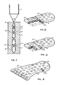
- FIG. 1 of the accompanying drawings there is illustrated an injection moulding machine 1 and first and second mould halves 10 and 11 between which an air cushion shoe sole 2 is being manufactured.
- a substantially cylindrical tubular bag of polyurethane is blown from the injection moulding machine and this cylinder is then laterally compressed between the mould halves 10 and 11 which are gradually brought together to the position illustrated.
- rod members i.e. members 101 in mould half 10 and members 111 in mould half 11.
- the rods of one mould half are positioned to match exactly the positions of the rods in the other mould half.
- a plurality of pairs of short rods having a height slightly less than half of the height of the resulting air cushion are provided and face one another.
- the polyurethane material is thus pinched between the mould halves at the positions of the rod pairs.
- a sharp air needle is inserted through an air hole made in one of the mould halves and the air is pumped into the interior of the polyurethane bag.
- the bag is inflated under pressure and forced into interior contact with the mould halves so that it receives exactly the shape of these mould halves.
- the inflated polyurethane cushion 2 has a "cubical" shape, i.e.
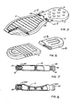
- Figures 2 to 4 show various embodiments of portions of a shoe sole which may be manufactured with the apparatus of Figure 1.
- the Figures also show air valves 22 on the two sides of the air cushion.
- These air valves are preferably of the type used in rubber balls and thus enable the shoe sole to be inflated by means of a normal ball needle or a simple air pump thus increasing the pressure within the air cushion 2 for improved buffer elasticity.
- These valves will be described in more detail here thoughinafter.
- the cushion sole may thus be inflated with gas or liquid (e.g. water) for weight adjustment.
- valves 22 are preferably provided, they are not essential if the desired final pressure is achieved in the manufacturing process by inflation between the mould halves.
- Figure 5 illustrates an embodiment in which two sole parts or air cushions are loosely joined together in the vicinity of the arch of the foot.
- Two tubular inflation members or valves 22 are provided also in the region of the arch, one member for each portion of the sole.
- the rear portion of the sole is provided with the circular depression points 21 in accordance with the embodiments of Figures 2 to 4 which have been formed by means of the rod members 101, 111 as illustrated in Figure 1.
- the front portion of the sole in Figure 5 is configured differently. In place of a plurality of circular depressions, it is provided with a plurality of elongate depressions which nevertheless achieve the effect of a plurality of pinch points giving rise to vertical wall sections of the sole portion extending from the upper to the lower surface.
- both the front and rear portions of the sole of Figure 5 are able to provide a degree of self-supporting function so that the sole will support the wearer even when not inflated.
- the front portion of the sole of Figure 5 may be manufactured by methods similar to that illustrated in Figure 1 but of course the rod like extensions 101, 111 will be replaced by elongate bar-like extensions.
- Figure 6 illustrates a further possibility in which the front and rear portions of the sole are not attached together but will be simply built into a single sole and attached together by the surrounding material.
- the configuration in Figure 6 is analogous to that illustrated in respect of the front portion of the sole in Figure 5.
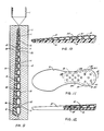
- each tube 22 is of an elastomer such as rubber and is therefore relatively soft.
- a flange 23 is provided and the tube is inserted into a suitable aperture formed in the cushion sole up to the flange.
- a plurality of anti-burst rings 221 are provided around the material of the cushion member where it abuts the tube 22. This ensures that the tube 22 will normally remain sealed but will open to avoid bursting of the cushion when sudden violent pressure increases occur within the cushion such as when the wearer lands on one foot from a height of several feet. Sealing of the tube is also effected by the provision of inclined surfaces on the interior end of the tube with the result that the interior pressure tends to force the tube to a closed condition.
- tubular sleeve 222 may be employed with the same effect.
- the tube valve members shown in Figures 7 and 8 may be employed in any of the embodiments illustrated in Figures 2 to 6. All the embodiments illustrated in these Figures may be manufactured by a method illustrated in Figure 1 by selecting a suitable pair of mould halves.
- the air cushion portion of the sole can be placed easily at any part of the foot and shaped by choice of an appropriate mould for practical requirements at any position such as at the front of the sole, the heel etc.
- a cloth layer made of natural or synthetic fibre may be adhered to the outer edge.
- Figure 9 shows a first method of manufacturing such a multi-layer sole.
- the method is basically the same as that illustrated with respect to Figure 1, but with this difference: a rubber sole portion 4 is inlaid in the first mould half 10 before the two halves are pressed together and the cushion part is inflated. Adhesive is applied to the surface of the rubber part 4 to ensure a good bond.
- the polyurethane film is expanded within the mould by the injection of air, it adheres to the rubber sole thus forming a multi-layer composite sole in one step.
- the rods 101 in the mould half 10 must be of additional length in order to protrude through apertures provided in the rubber sole 4.
- FIG. 11 and 12 Another method of forming a composite sole is illustrated in Figures 11 and 12. After manufacture of the cushion member in accordance with the method of Figure 1, the air cushion 2 is placed within a polyurethane sole so that the air cushion 2 is hidden and remains invisible in the final sole.
- a hole 211 may be cut in the center of each of the pinch points 21 so that the injection material of the polyurethane layer surrounding the air cushion 2 will penetrate through the air cushion thus forming vertical rods 31 connecting the upper and lower polyurethane layers and acting as an auxiliary support structure to strengthen the supporting power of the air cushion 2 up to 80 psi when the air cushion sole is inflated.
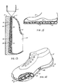
- Figure 13 illustrates a third method according to which a rubber sole and the shoe upper is fixed together with the cushion sole in one operation.
- the right-hand mould half 11 is replaced by a shoe mould 51 surrounded by an upper 5.
- the mould half 10 provided with the rubber sole insert 4 is pressed against the shoe mould 51 with its upper 5.
- Short rods 101 of the mould half 10 penetrate the rubber sole 4 and have a length slightly less than that of the desired air cushion.
- the air cushion can be adhered and secured between the upper 5 and the sole 4 while the blow mould shaping is done thus forming a complete shoe with its upper 5, and air cushion 2 and the sole 4 all adhered together in one process.
- Figures 14 and 15 show shoes manufactured in accordance with this method. Of course, such shoes can also be assembled from the various components by adhering the sole and the cushion member to the upper by manual processing.
- the air cushions 2 described up to this point have each had only a single chamber. It is also possible however to shape the mould halves 10 and 11 to manufacture an air cushion 20 having two chambers as shown in Figures 16 and 17. Each of the chambers 201, 202 is provided with a respective air valve 22 to enable adjustment of the pressure within each chamber independently. This may be useful in order to prevent the ankle of the wearer from being sprained or injured by turning at the instant of making contact with the ground of the inner edge or outer edge of the foot. The pressures within the two chambers can be adjusted according to the wearer's own particular requirements.
- a single air cushion 2 may also be made to comprise a plurality of chambers.
- the lower side of the air cushion 2 or 20 can be thickened such that no rubber sole 4 is needed and the air cushions 2 or 20 can directly contact the ground as shown in the embodiment of Figure 15.
- valve members 22 illustrated in Figures 7 and 8 may of course be employed in the embodiments of Figures 9 to 17 as well as those of Figures 1 to 6.
- the valves may be positioned in the region of the arch of the foot or on the shoe centre line in the heel portion facing to the rear.
- each tube 6 in this embodiment is effectively an extension of the valve member illustrated in Figures 7 and 8.
- the air cushion made by the blow-mould shaping according to the invention not only has a high degree of self-support but also may be inflated with air or a liquid and makes it simple to interchange air and liquid.
- the pressure of the inflated air may range from 0 to 80 psi so that the wearer can adjust the pressure to that most suitable according to his weight and needs.
- the pressure adjustment may be easily carried out by means of a ball air needle or an air pump.
- a variety of air cushions can be manufactured of different shape, design or outline.
Abstract
Description
- This invention relates to shoe soles, methods of manufacturing shoe soles and shoes provided with such a sole.
- Owing to the conditions under which they are used, sport shoes should provide a degree of impact resistance or buffer elasticity in order to protect the wearer from jars or shocks to his leg which may occur as a result of stumbling or falling awkwardly or which may occur as the natural course of events owing to the nature of the sport concerned.
- Usually, the impact resistance or buffer elasticity of a sports shoe depends on the degree of softness of the material used for the sole. The weight of the shoe is also directly affected by that of the sole. Various attempts have been made to produce a light and elastic sports shoe and successive improvements in manufacturing technique for the production of such a shoe will be described in the following:
- 1. Initially light and elastic materials such as polyurethane was used to make soles for sport shoes. Owing to its constant density and fixed elasticity however this method cannot suitably meet the requirements of good impact resistance and anti-shock properties for wearers of different body weight and for use in different types of sport. In addition, with the use of a fixed density and elasticity, there is a danger that the wearer's ankle may be sprained or injured when his foot is placed down violently into contact with the ground owing to the large variety of leg and food movements employed by the various individuals when placing the heel against the ground.
- 2. In order to prevent the wearer's ankle from being sprained or injured when making contact with the ground, shoe manufacturers have attempted to provide a combination of two different materials with different densities (hardness) for soles. But since the location and hardness of the two different materials is fixed once the decision has been made, the density cannot be adjusted. Thus, in manufacture, a variety of soles with various elastic parts in different locations are manufactured to meet different individual requirements. Although such a sole may meet an individual requirement concerning placement of the foot on landing, it cannot be adjusted according to an individual's weight, according to the type of sport or according to the different requirements of elasticity. Therefore, it is still far away from a fully satisfactory solution.
- 3. In an attempt to meet this problem, an air cushion sole has been proposed which provides a pressurized buffer elasticity and therefore offers better shock absorption and comfort. Nevertheless, since such a sole is inflated to a constant pressure and cannot be inflated or deflated by the user it cannot meet the requirements of different individual's weight and different required buffer elasticity in various sports. It is thus incapable of meeting individual requirements. In addition, if the pressure should be reduced owing to an air-leak, the air cushion will flatten and lose practically all its supporting ability. The sole will thus reduce its height and become virtually useless.
- 4. In order to avoid the problem that the pressure in the sole cannot be adjusted, an air cushion is known provided with an air valve. This air valve is the same as that used for bicycle tyres. The air cushion itself is manufactured by the conventionally used method of sealing two pieces of synthetic material together with application of heat. A volatile liquid is placed between the two pieces which evaporates to form a gas at room temperature thus inflating the cushion. But a single metallic air valve placed on the sole feels hard to the wearer while walking and also impairs comfort. In addition, such an air valve needs a bicycle pump to inflate the air cushion which is inconvenient for the user. Furthermore, since the air cushion is made of two pieces sealed together by heat, once it has been punctured by a sharp pointed implement and the air inside has leaked out, it flattens losing it original elasticity and support in the same manner as the prior art already mentioned. Its practical value and service life are both therefore limited.
- The method of manufacturing this known air cushion is as follows. First, the raw material is made into a sheet and then the desired shape and size is cut out and two similar pieces are placed together facing each other and sealed together with the application of heat to form a flat bag into which is then introduced the liquid which evaporates at room temperature to inflate the bag. The bag is finally completely sealed. If it is desired to provide the air valve, the above mentioned cushion bag is normally provided with the valve which prevents excess pressure above 25 psi from being achieved thus preventing the cushion bag from bursting. The valve is set as close as possible to the outer edge whilst the cushion is enclosed by a wrapping layer. The valve may not be exposed to the exterior in order to avoid presenting a hinderance to walking or damage. Thus, the valve is hidden in the wrapping layer so that the wearer feels its presence and is therefore uncomfortable during walking.
- Of course, if no valve is provided, this known air cushion is filled with air or the volatile liquid and is therefore unable to change its properties easily.
- One object of the present invention is to provide a shoe sole which can be inflated to any desired pressure in a simple manner without sacrificing comfort.
- Another object of the invention is to provide a simple method of manufacturing a robust inflatable shoe sole.
- Another object of the invention is to provide an inflatable shoe sole which is not completely reliant on inflation for its buffer elasticity and shock absorbing properties.
- According to one aspect of the invention, there is provided a method for manufacturing a shoe sole characterized by:
- a) blow moulding a tubular polyurethane film;
- b) pressing the film between a pair of mould halves; and
pumping gas into the film to press it into interior contact with the mould halves. - According to another aspect of the invention there is provided an inflatable shoe sole characterized in that the shoe sole comprises an upper layer and a lower layer between which an inflatable chamber is defined and in that a plurality of wall segments extend substantially perpendicularly between the upper and lower layers.
- For a better understanding of the invention and to show how the same may be carried into effect, reference will now be made by way of example to the accompanying drawings in which;
- Figure 1 is a cross-sectional view of one step in the manufacture of a shoe sole according to one emboduiment of the present invention;
- Figure 2 is a perspective view partially in section of part of a shoe sole manufactured in accordance with the method of Figure 1;
- Figure 3 is a perspective view of second embodiment of part of a shoe sole which may be manufactured in accordance with the method illustrated in Figure 1;
- Figure 4 shows a perspective view of a further embodiment according to the invention;
- Figure 5 shows a complete shoe sole, partially in section in accordance with a further embodiment of the invention;
- Figure 6 shows components of a shoe sole partially in section according to a further embodiment of the invention;
- Figure 7 is a partial sectional view along the lines 7-7 Figure 5;
- Figure 8 is a partial sectional view in accordance with the section line 8-8 of Figure 6 but with the addition of valve members;
- Figure 9 shows a step in the manufacture of a shoe sole according to a further embodiment of the invention;
- Figure 10 shows a composite shoe sole manufactured in accordance with another method according to the invention;
- Figure 11 shows a plan view of a further shoe sole in accordance with a further embodiment of the invention;
- Figure 12 shows a lateral view partially in section along the line 12-12 of Figure 11;
- Figure 13 shows one step in the manufacture of a shoe sole according to a further embodiment of the invention;
- Figure 14 shows a whole shoe including a sole partially in section according to further emdodiment of the invention;
- Figure 15 is a side view partially in section of a complete shoe including a sole according to a further embodiment of the invention;
- Figure 16 shows part of a shoe sole comprising two separate chambers according to a further embodiment of the invention;
- Figure 17 shows a sectional view along the line 17-17 of Figure 16;
- Figure 18 shows a tube member for use in inflating the shoe sole according to the invention; and
- Figure 19 shows a plan view of a shoe sole including the air tube of Figure 18.
- Referring now to Figure 1 of the accompanying drawings, there is illustrated an injection moulding machine 1 and first and second mould halves 10 and 11 between which an air cushion shoe sole 2 is being manufactured. Before the step illustrated in Figure 1 is reached, a substantially cylindrical tubular bag of polyurethane is blown from the injection moulding machine and this cylinder is then laterally compressed between the mould halves 10 and 11 which are gradually brought together to the position illustrated. Contained within each mould half, are provided a plurality of rod members, i.e.
members 101 inmould half 10 andmembers 111 inmould half 11. The rods of one mould half are positioned to match exactly the positions of the rods in the other mould half. Thus, a plurality of pairs of short rods having a height slightly less than half of the height of the resulting air cushion are provided and face one another. When the mould halves are brought together, the polyurethane material is thus pinched between the mould halves at the positions of the rod pairs. Following this step, a sharp air needle is inserted through an air hole made in one of the mould halves and the air is pumped into the interior of the polyurethane bag. As a result, the bag is inflated under pressure and forced into interior contact with the mould halves so that it receives exactly the shape of these mould halves. In the vicinity of the rod pairs, theinflated polyurethane cushion 2 has a "cubical" shape, i.e. it has a plurality of vertical wall parts formed adjacent therods short rods pinch points 21 when the mould halves 10, 11 are brought together, the material around thesepoints 21 can help support theair cushion 2 itself with buffer elasticity to allow continuous use of the air cushion even when it is not inflated or if theair cushion 2 becomes punctured or torn by a sharp-pointed implement. It has proved that anair cushion 2 manufactured in this manner is able to withstand a pressure up to 40 psi. - Figures 2 to 4 show various embodiments of portions of a shoe sole which may be manufactured with the apparatus of Figure 1. The Figures also show
air valves 22 on the two sides of the air cushion. These air valves are preferably of the type used in rubber balls and thus enable the shoe sole to be inflated by means of a normal ball needle or a simple air pump thus increasing the pressure within theair cushion 2 for improved buffer elasticity. These valves will be described in more detail hereinafter. The cushion sole may thus be inflated with gas or liquid (e.g. water) for weight adjustment. - Although the
valves 22 are preferably provided, they are not essential if the desired final pressure is achieved in the manufacturing process by inflation between the mould halves. - Figure 5 illustrates an embodiment in which two sole parts or air cushions are loosely joined together in the vicinity of the arch of the foot. Two tubular inflation members or
valves 22 are provided also in the region of the arch, one member for each portion of the sole. - As will be further apparent from Figure 5, the rear portion of the sole is provided with the circular depression points 21 in accordance with the embodiments of Figures 2 to 4 which have been formed by means of the
rod members - The front portion of the sole of Figure 5 may be manufactured by methods similar to that illustrated in Figure 1 but of course the rod like
extensions - Figure 6 illustrates a further possibility in which the front and rear portions of the sole are not attached together but will be simply built into a single sole and attached together by the surrounding material. The configuration in Figure 6 is analogous to that illustrated in respect of the front portion of the sole in Figure 5.
- Coming now to Figures 7 and 8, the construction of the inflation tubes or
valves 22 may be seen in more detail. Eachtube 22 is of an elastomer such as rubber and is therefore relatively soft. Towards the exterior end of each tube, aflange 23 is provided and the tube is inserted into a suitable aperture formed in the cushion sole up to the flange. In the embodiment of Figure 7, a plurality ofanti-burst rings 221 are provided around the material of the cushion member where it abuts thetube 22. This ensures that thetube 22 will normally remain sealed but will open to avoid bursting of the cushion when sudden violent pressure increases occur within the cushion such as when the wearer lands on one foot from a height of several feet. Sealing of the tube is also effected by the provision of inclined surfaces on the interior end of the tube with the result that the interior pressure tends to force the tube to a closed condition. - As shown in Figure 8, in place of the rings 221 a
tubular sleeve 222 may be employed with the same effect. - The tube valve members shown in Figures 7 and 8 may be employed in any of the embodiments illustrated in Figures 2 to 6. All the embodiments illustrated in these Figures may be manufactured by a method illustrated in Figure 1 by selecting a suitable pair of mould halves. The air cushion portion of the sole can be placed easily at any part of the foot and shaped by choice of an appropriate mould for practical requirements at any position such as at the front of the sole, the heel etc. In order to enhance the appearance of the resulting sole, a cloth layer made of natural or synthetic fibre may be adhered to the outer edge.
- It is also possible to utilize the air cushion sole portions in combination with a further layer of rubber to form a multi-layer sole.
- Figure 9 shows a first method of manufacturing such a multi-layer sole. The method is basically the same as that illustrated with respect to Figure 1, but with this difference: a rubber
sole portion 4 is inlaid in thefirst mould half 10 before the two halves are pressed together and the cushion part is inflated. Adhesive is applied to the surface of therubber part 4 to ensure a good bond. Thus, when the polyurethane film, is expanded within the mould by the injection of air, it adheres to the rubber sole thus forming a multi-layer composite sole in one step. Of course, in order to achieve the pinching effect of therod members 101 in this method, therods 101 in themould half 10 must be of additional length in order to protrude through apertures provided in therubber sole 4. - It is of course also possible to adhere the rubber sole 4 to the cushion member after the cushion member has been formed in the mould, as illustrated in Figure 10. In this case, a composite sole is achieved without the provision or necessity for any apertures in the
rubber sole 4. - Another method of forming a composite sole is illustrated in Figures 11 and 12. After manufacture of the cushion member in accordance with the method of Figure 1, the
air cushion 2 is placed within a polyurethane sole so that theair cushion 2 is hidden and remains invisible in the final sole. - Furthermore, in order to increase the self-supporting strength, a hole 211 may be cut in the center of each of the pinch points 21 so that the injection material of the polyurethane layer surrounding the
air cushion 2 will penetrate through the air cushion thus forming vertical rods 31 connecting the upper and lower polyurethane layers and acting as an auxiliary support structure to strengthen the supporting power of theair cushion 2 up to 80 psi when the air cushion sole is inflated. - Figure 13 illustrates a third method according to which a rubber sole and the shoe upper is fixed together with the cushion sole in one operation. In this method, the right-
hand mould half 11 is replaced by ashoe mould 51 surrounded by an upper 5. Thus, themould half 10 provided with the rubbersole insert 4 is pressed against theshoe mould 51 with its upper 5.Short rods 101 of themould half 10 penetrate therubber sole 4 and have a length slightly less than that of the desired air cushion. Thus, the air cushion can be adhered and secured between the upper 5 and the sole 4 while the blow mould shaping is done thus forming a complete shoe with its upper 5, andair cushion 2 and the sole 4 all adhered together in one process. - Figures 14 and 15 show shoes manufactured in accordance with this method. Of course, such shoes can also be assembled from the various components by adhering the sole and the cushion member to the upper by manual processing.
- The
air cushions 2 described up to this point have each had only a single chamber. It is also possible however to shape the mould halves 10 and 11 to manufacture anair cushion 20 having two chambers as shown in Figures 16 and 17. Each of thechambers respective air valve 22 to enable adjustment of the pressure within each chamber independently. This may be useful in order to prevent the ankle of the wearer from being sprained or injured by turning at the instant of making contact with the ground of the inner edge or outer edge of the foot. The pressures within the two chambers can be adjusted according to the wearer's own particular requirements. - Of course, a
single air cushion 2 may also be made to comprise a plurality of chambers. Moreover, by controlling the feeding of the injection moulding machine, the lower side of theair cushion rubber sole 4 is needed and theair cushions - The
valve members 22 illustrated in Figures 7 and 8 may of course be employed in the embodiments of Figures 9 to 17 as well as those of Figures 1 to 6. The valves may be positioned in the region of the arch of the foot or on the shoe centre line in the heel portion facing to the rear. - Finally, as shown in Figures 18 and 19, individual tubes 6 as shown in Figure 18 may be manufactured and inserted into the sole as shown in Figure 19. Each tube 6 in this embodiment is effectively an extension of the valve member illustrated in Figures 7 and 8.
- In conclusion, the air cushion made by the blow-mould shaping according to the invention not only has a high degree of self-support but also may be inflated with air or a liquid and makes it simple to interchange air and liquid. The pressure of the inflated air may range from 0 to 80 psi so that the wearer can adjust the pressure to that most suitable according to his weight and needs. The pressure adjustment may be easily carried out by means of a ball air needle or an air pump. Furthermore, by means of the method according to the invention, a variety of air cushions can be manufactured of different shape, design or outline. Even if the air cushion is not inflated, or is punctured by a sharp-pointed implement, it still possesses adequate supporting ability and buffer elasticity, thus increasing its practicality and service life. Furthermore, the anti-burst rings placed around the air valves can prevent the air cushion from bursting as a result of high pressure impact. As a result, air cushions made in accordance with the invention are superior to those previously known.
- Thus, the invention provides the following series of advantages:
- 1. An easy and rapid method is provided for manufacturing a hollow "cubical" air cushion which is manufactured by blow-mould shaping in one step and maintains a desired supporting buffer elasticity instead of merely flattening down even when it is not inflated or if it is punctured thus enabling continuous use even if it is damaged.
- 2. In the process of blow-mould shaping, a rubber sole applied with adhesive can be placed within the mould so at to combine with the air cushion thus directly manufacturing a shoe sole together with an air cushion in one step.
- 3. The air cushion may also be placed within an injection mould for a polyurethane sole, thus forming the sole together with a hidden air cushion which is invisible from outside.
- 4. Similarly as under
item 2 above, a rubber sole applied with adhesive as well as an upper applied with adhesive may be placed in the mould and respectively adhered to the cushion member. When blow-mould shaping is used, the process of manufacturing the whole shoe is thus simplified. - 5. In one or both sides of the air cushion made by blow-mould shaping, normal rubber air valves as used in rubber balls or footballs are placed at a position convenient for inflation or deflation and an anti-burst ring is fixed over the air valve so that when the pressure in the air cushion becomes to high the extra pressure may be released thus preventing the air cushion from rupturing.
- 6. Such an air cushion made by blow-mould shaping has a structure which is able to meet practical requirements, thus possibly being inflated up to a pressure of 40 psi and to 80 psi for adjustment of buffer elasticity after insertion into the sole thus meeting the requirements of different body weights or sports.
- 7. The pressure may thus be adjusted easily by means of an air needle or an air pump according to the user's wishes.
- 8. The air cushion according to the invention may be inflated by air or any other liquid to change the shoe weight if necessary, and the operation for changing the contents can be carried out easily and conveniently.
- 9. A two-chamber air cushion may also be manufactured by blow-mould shaping and each chamber may be provided with its own air valve for inflation with differing air pressures. Thus, individual habits of foot contact (interior edge or exterior edge of the heel contacting first) may be met. In addition, the two-chamber cushion may be designed according to the turning theory at the very moment of contact with the ground while doing exercise, so that it can effectively prevent the ankle from being sprained or injured.
- 10. The air cushion sole according to the invention can be freely adjusted in buffer elasticity according to each individual's weight, desire and according to the type of sport involved.
Claims (14)
Priority Applications (3)
| Application Number | Priority Date | Filing Date | Title |
|---|---|---|---|
| AT85112172T ATE58823T1 (en) | 1985-09-25 | 1985-09-25 | AIR CUSHION COMPONENTS FOR SHOE SOLES AND PROCESS FOR THEIR MANUFACTURE. |
| DE8585112172T DE3580849D1 (en) | 1985-09-25 | 1985-09-25 | AIR CUSHION COMPONENTS FOR SHOE SOLE AND METHOD FOR THE PRODUCTION THEREOF. |
| KR1019850008648A KR900001387B1 (en) | 1985-09-25 | 1985-11-19 | Air cushion shoe sole |
Applications Claiming Priority (1)
| Application Number | Priority Date | Filing Date | Title |
|---|---|---|---|
| AU46609/85A AU564808B2 (en) | 1985-08-23 | 1985-08-23 | Manufacturing shoe soles with an air cushion |
Publications (2)
| Publication Number | Publication Date |
|---|---|
| EP0215974A1 true EP0215974A1 (en) | 1987-04-01 |
| EP0215974B1 EP0215974B1 (en) | 1990-12-05 |
Family
ID=3733606
Family Applications (1)
| Application Number | Title | Priority Date | Filing Date |
|---|---|---|---|
| EP85112172A Expired EP0215974B1 (en) | 1985-08-23 | 1985-09-25 | Air-cushioned shoe sole components and method for their manufacture |
Country Status (2)
| Country | Link |
|---|---|
| EP (1) | EP0215974B1 (en) |
| AU (1) | AU564808B2 (en) |
Cited By (20)
| Publication number | Priority date | Publication date | Assignee | Title |
|---|---|---|---|---|
| EP0293034A2 (en) * | 1987-05-29 | 1988-11-30 | Armenak Moumdjian | Pneumatic sole for footwear and a corresponding mould and moulding method |
| US4817304A (en) * | 1987-08-31 | 1989-04-04 | Nike, Inc. And Nike International Ltd. | Footwear with adjustable viscoelastic unit |
| DE9413588U1 (en) * | 1994-08-23 | 1995-03-30 | Adidas Ag | Outsole with bulges serving as sound parts |
| FR2722663A1 (en) * | 1994-07-25 | 1996-01-26 | Chalas Georges | Hollow pneumatic footwear sole |
| WO1996016564A1 (en) * | 1994-12-02 | 1996-06-06 | Nike International Ltd. | Cushioning device for a footwear sole and method for making the same |
| GB2323264A (en) * | 1997-03-21 | 1998-09-23 | Wayne Wang | Pneumatic sole |
| EP1025976A2 (en) * | 1999-02-03 | 2000-08-09 | Lanfranco Anzani | Process for the formation of vulcanized hollow bodies, and the hollow bodies so obtained |
| US6298499B1 (en) | 1988-04-11 | 2001-10-09 | Ing-Chung Huang | Removable, pressure-adjustable, shock absorbing cushion device with an inflation pump for sport goods |
| US6584706B1 (en) | 1990-01-10 | 2003-07-01 | Anatomic Research, Inc. | Shoe sole structures |
| US6871421B2 (en) * | 2001-09-21 | 2005-03-29 | Daniel R. Potter | Footwear with bladder type stabilizer |
| US7707745B2 (en) | 2003-07-16 | 2010-05-04 | Nike, Inc. | Footwear with a sole structure incorporating a lobed fluid-filled chamber |
| US7707744B2 (en) | 2003-07-16 | 2010-05-04 | Nike, Inc. | Footwear with a sole structure incorporating a lobed fluid-filled chamber |
| US7774955B2 (en) | 2005-10-03 | 2010-08-17 | Nike, Inc. | Article of footwear with a sole structure having fluid-filled support elements |
| US7950169B2 (en) | 2007-05-10 | 2011-05-31 | Nike, Inc. | Contoured fluid-filled chamber |
| US8657979B2 (en) | 2003-12-23 | 2014-02-25 | Nike, Inc. | Method of manufacturing a fluid-filled bladder with a reinforcing structure |
| US20150273778A1 (en) * | 2013-02-21 | 2015-10-01 | Nike, Inc. | Method of Co-Molding |
| US9642411B2 (en) | 2004-11-22 | 2017-05-09 | Frampton E. Ellis | Surgically implantable device enclosed in two bladders configured to slide relative to each other and including a faraday cage |
| US9750307B2 (en) | 2013-02-21 | 2017-09-05 | Nike, Inc. | Article of footwear having a sole structure including a fluid-filled chamber and an outsole, the sole structure, and methods for manufacturing |
| WO2018103811A1 (en) * | 2016-12-08 | 2018-06-14 | Puma SE | Method for producing a shoe sole |
| EP4201246A1 (en) * | 2021-12-22 | 2023-06-28 | Puma Se | Method for producing a sole of a shoe |
Families Citing this family (21)
| Publication number | Priority date | Publication date | Assignee | Title |
|---|---|---|---|---|
| US6675498B1 (en) | 1988-07-15 | 2004-01-13 | Anatomic Research, Inc. | Shoe sole structures |
| US6708424B1 (en) | 1988-07-15 | 2004-03-23 | Anatomic Research, Inc. | Shoe with naturally contoured sole |
| US6668470B2 (en) | 1988-09-02 | 2003-12-30 | Anatomic Research, Inc. | Shoe sole with rounded inner and outer side surfaces |
| US6163982A (en) | 1989-08-30 | 2000-12-26 | Anatomic Research, Inc. | Shoe sole structures |
| US6729046B2 (en) | 1989-08-30 | 2004-05-04 | Anatomic Research, Inc. | Shoe sole structures |
| US6789331B1 (en) | 1989-10-03 | 2004-09-14 | Anatomic Research, Inc. | Shoes sole structures |
| EP1004252B1 (en) | 1989-10-03 | 2002-03-06 | Anatomic Research, Inc. | Shoe sole with a midsole having firmness and density variations |
| US7546699B2 (en) | 1992-08-10 | 2009-06-16 | Anatomic Research, Inc. | Shoe sole structures |
| USD385394S (en) | 1996-08-27 | 1997-10-28 | Nike, Inc. | Bladder for shoe sole |
| US7634529B2 (en) | 1996-11-29 | 2009-12-15 | Ellis Iii Frampton E | Personal and server computers having microchips with multiple processing units and internal firewalls |
| US6385864B1 (en) | 2000-03-16 | 2002-05-14 | Nike, Inc. | Footwear bladder with controlled flex tensile member |
| US6457262B1 (en) | 2000-03-16 | 2002-10-01 | Nike, Inc. | Article of footwear with a motion control device |
| US6374514B1 (en) | 2000-03-16 | 2002-04-23 | Nike, Inc. | Footwear having a bladder with support members |
| US6402879B1 (en) | 2000-03-16 | 2002-06-11 | Nike, Inc. | Method of making bladder with inverted edge seam |
| US6571490B2 (en) | 2000-03-16 | 2003-06-03 | Nike, Inc. | Bladder with multi-stage regionalized cushioning |
| US8291618B2 (en) | 2004-11-22 | 2012-10-23 | Frampton E. Ellis | Devices with internal flexibility sipes, including siped chambers for footwear |
| WO2006058013A2 (en) | 2004-11-22 | 2006-06-01 | Ellis, Frampton, E. | Devices with internal flexibility sipes, including siped chambers for footwear |
| US7622014B2 (en) | 2005-07-01 | 2009-11-24 | Reebok International Ltd. | Method for manufacturing inflatable footwear or bladders for use in inflatable articles |
| US8125796B2 (en) | 2007-11-21 | 2012-02-28 | Frampton E. Ellis | Devices with faraday cages and internal flexibility sipes |
| US8572786B2 (en) | 2010-10-12 | 2013-11-05 | Reebok International Limited | Method for manufacturing inflatable bladders for use in footwear and other articles of manufacture |
| CN105172057A (en) * | 2015-10-22 | 2015-12-23 | 福建隆盛轻工有限公司 | Making mould of hollow shoe sole |
Citations (6)
| Publication number | Priority date | Publication date | Assignee | Title |
|---|---|---|---|---|
| FR1164720A (en) * | 1957-01-11 | 1958-10-14 | Improvements in soles for footwear | |
| FR1190358A (en) * | 1958-01-22 | 1959-10-12 | Seprol | New sole for shoes |
| GB1067222A (en) * | 1963-07-08 | 1967-05-03 | Werner Battenfeld | Method of and apparatus for manufacturing hollow bodies of plastics material by blow moulding |
| FR2052268A5 (en) * | 1969-06-14 | 1971-04-09 | Fukuoka Tatsuo | |
| FR2185106A5 (en) * | 1972-05-17 | 1973-12-28 | Pontvert Sa Richard | |
| GB2085797A (en) * | 1980-10-17 | 1982-05-06 | Teraoka Syoichi | Molding hollow plastics articles |
-
1985
- 1985-08-23 AU AU46609/85A patent/AU564808B2/en not_active Ceased
- 1985-09-25 EP EP85112172A patent/EP0215974B1/en not_active Expired
Patent Citations (6)
| Publication number | Priority date | Publication date | Assignee | Title |
|---|---|---|---|---|
| FR1164720A (en) * | 1957-01-11 | 1958-10-14 | Improvements in soles for footwear | |
| FR1190358A (en) * | 1958-01-22 | 1959-10-12 | Seprol | New sole for shoes |
| GB1067222A (en) * | 1963-07-08 | 1967-05-03 | Werner Battenfeld | Method of and apparatus for manufacturing hollow bodies of plastics material by blow moulding |
| FR2052268A5 (en) * | 1969-06-14 | 1971-04-09 | Fukuoka Tatsuo | |
| FR2185106A5 (en) * | 1972-05-17 | 1973-12-28 | Pontvert Sa Richard | |
| GB2085797A (en) * | 1980-10-17 | 1982-05-06 | Teraoka Syoichi | Molding hollow plastics articles |
Cited By (44)
| Publication number | Priority date | Publication date | Assignee | Title |
|---|---|---|---|---|
| EP0293034A3 (en) * | 1987-05-29 | 1990-11-22 | Armenak Moumdjian | Pneumatic sole for footwear and a corresponding mould and moulding method |
| EP0293034A2 (en) * | 1987-05-29 | 1988-11-30 | Armenak Moumdjian | Pneumatic sole for footwear and a corresponding mould and moulding method |
| US4817304A (en) * | 1987-08-31 | 1989-04-04 | Nike, Inc. And Nike International Ltd. | Footwear with adjustable viscoelastic unit |
| US6298499B1 (en) | 1988-04-11 | 2001-10-09 | Ing-Chung Huang | Removable, pressure-adjustable, shock absorbing cushion device with an inflation pump for sport goods |
| US6460197B2 (en) | 1988-04-11 | 2002-10-08 | Ing-Chung Huang | Removable, pressure-adjustable, shock-absorbing cushion device with an inflation pump for sports goods |
| US7234249B2 (en) | 1990-01-10 | 2007-06-26 | Anatomic Reseach, Inc. | Shoe sole structures |
| US6584706B1 (en) | 1990-01-10 | 2003-07-01 | Anatomic Research, Inc. | Shoe sole structures |
| FR2722663A1 (en) * | 1994-07-25 | 1996-01-26 | Chalas Georges | Hollow pneumatic footwear sole |
| WO1996005747A1 (en) * | 1994-08-23 | 1996-02-29 | Adidas Ag | Outsole with ground contacting bulges |
| DE9413588U1 (en) * | 1994-08-23 | 1995-03-30 | Adidas Ag | Outsole with bulges serving as sound parts |
| WO1996016564A1 (en) * | 1994-12-02 | 1996-06-06 | Nike International Ltd. | Cushioning device for a footwear sole and method for making the same |
| GB2323264A (en) * | 1997-03-21 | 1998-09-23 | Wayne Wang | Pneumatic sole |
| EP1025976A3 (en) * | 1999-02-03 | 2000-11-15 | Lanfranco Anzani | Process for the formation of vulcanized hollow bodies, and the hollow bodies so obtained |
| EP1025976A2 (en) * | 1999-02-03 | 2000-08-09 | Lanfranco Anzani | Process for the formation of vulcanized hollow bodies, and the hollow bodies so obtained |
| US6503355B1 (en) | 1999-02-03 | 2003-01-07 | Lanfranco Anzani | Process for the formation of vulcanized hollow bodies |
| KR100644748B1 (en) * | 1999-02-03 | 2006-11-13 | 안자니 란프란코 | Process for the formation of vulcanized hollow bodies, and the hollow bodies so obtained |
| US6871421B2 (en) * | 2001-09-21 | 2005-03-29 | Daniel R. Potter | Footwear with bladder type stabilizer |
| US7707745B2 (en) | 2003-07-16 | 2010-05-04 | Nike, Inc. | Footwear with a sole structure incorporating a lobed fluid-filled chamber |
| US7707744B2 (en) | 2003-07-16 | 2010-05-04 | Nike, Inc. | Footwear with a sole structure incorporating a lobed fluid-filled chamber |
| US8657979B2 (en) | 2003-12-23 | 2014-02-25 | Nike, Inc. | Method of manufacturing a fluid-filled bladder with a reinforcing structure |
| US10021938B2 (en) | 2004-11-22 | 2018-07-17 | Frampton E. Ellis | Furniture with internal flexibility sipes, including chairs and beds |
| US11503876B2 (en) | 2004-11-22 | 2022-11-22 | Frampton E. Ellis | Footwear or orthotic sole with microprocessor control of a bladder with magnetorheological fluid |
| US9642411B2 (en) | 2004-11-22 | 2017-05-09 | Frampton E. Ellis | Surgically implantable device enclosed in two bladders configured to slide relative to each other and including a faraday cage |
| US9681696B2 (en) | 2004-11-22 | 2017-06-20 | Frampton E. Ellis | Helmet and/or a helmet liner including an electronic control system controlling the flow resistance of a magnetorheological liquid in compartments |
| US11039658B2 (en) | 2004-11-22 | 2021-06-22 | Frampton E. Ellis | Structural elements or support elements with internal flexibility sipes |
| US7774955B2 (en) | 2005-10-03 | 2010-08-17 | Nike, Inc. | Article of footwear with a sole structure having fluid-filled support elements |
| US8302234B2 (en) | 2005-10-03 | 2012-11-06 | Nike, Inc. | Article of footwear with a sole structure having fluid-filled support elements |
| US8302328B2 (en) | 2005-10-03 | 2012-11-06 | Nike, Inc. | Article of footwear with a sole structure having fluid-filled support elements |
| US8312643B2 (en) | 2005-10-03 | 2012-11-20 | Nike, Inc. | Article of footwear with a sole structure having fluid-filled support elements |
| US8656608B2 (en) | 2005-10-03 | 2014-02-25 | Nike, Inc. | Article of footwear with a sole structure having fluid-filled support elements |
| US7810256B2 (en) | 2005-10-03 | 2010-10-12 | Nike, Inc. | Article of footwear with a sole structure having fluid-filled support elements |
| US7950169B2 (en) | 2007-05-10 | 2011-05-31 | Nike, Inc. | Contoured fluid-filled chamber |
| US9987814B2 (en) * | 2013-02-21 | 2018-06-05 | Nike, Inc. | Method of co-molding |
| US10441029B2 (en) | 2013-02-21 | 2019-10-15 | Nike, Inc. | Article of footwear having a sole structure including a fluid-filled chamber and an outsole, the sole structure, and methods for manufacturing |
| US9750307B2 (en) | 2013-02-21 | 2017-09-05 | Nike, Inc. | Article of footwear having a sole structure including a fluid-filled chamber and an outsole, the sole structure, and methods for manufacturing |
| US11470915B2 (en) | 2013-02-21 | 2022-10-18 | Nike, Inc. | Article of footwear having a sole structure including a fluid-filled chamber and an outsole, the sole structure, and methods for manufacturing |
| US20150273778A1 (en) * | 2013-02-21 | 2015-10-01 | Nike, Inc. | Method of Co-Molding |
| WO2018103811A1 (en) * | 2016-12-08 | 2018-06-14 | Puma SE | Method for producing a shoe sole |
| KR20180128477A (en) * | 2016-12-08 | 2018-12-03 | 푸마 에스이 | How to make shoe sole |
| CN109070433A (en) * | 2016-12-08 | 2018-12-21 | 彪马欧洲股份公司 | A kind of manufacturing method of sole |
| JP2019518624A (en) * | 2016-12-08 | 2019-07-04 | プーマ エス イーPuma Se | How to make a shoe sole |
| KR102155862B1 (en) * | 2016-12-08 | 2020-09-15 | 푸마 에스이 | How to make a shoe sole |
| US10856606B2 (en) | 2016-12-08 | 2020-12-08 | Puma SE | Method for producing a shoe sole |
| EP4201246A1 (en) * | 2021-12-22 | 2023-06-28 | Puma Se | Method for producing a sole of a shoe |
Also Published As
| Publication number | Publication date |
|---|---|
| AU4660985A (en) | 1987-02-26 |
| EP0215974B1 (en) | 1990-12-05 |
| AU564808B2 (en) | 1987-08-27 |
Similar Documents
| Publication | Publication Date | Title |
|---|---|---|
| EP0215974A1 (en) | Air-cushioned shoe sole components and method for their manufacture | |
| US4670995A (en) | Air cushion shoe sole | |
| US5353459A (en) | Method for inflating a bladder | |
| US5916664A (en) | Multi-celled cushion and method of its manufacture | |
| CA1068108A (en) | Insole construction of articles of footwear | |
| US4219945A (en) | Footwear | |
| US4217705A (en) | Self-contained fluid pressure foot support device | |
| US7409780B2 (en) | Bellowed chamber for a shoe | |
| CA1337956C (en) | Shock absorbing system for footwear application | |
| US5443529A (en) | Prosthetic device incorporating multiple sole bladders | |
| US4887367A (en) | Shock absorbing shoe sole and shoe incorporating the same | |
| US5979078A (en) | Cushioning device for a footwear sole and method for making the same | |
| US4864738A (en) | Sole construction for footwear | |
| US7448150B1 (en) | Insert with variable cushioning and support and article of footwear containing same | |
| US5014449A (en) | Shoe sole construction | |
| US4342157A (en) | Shock absorbing partially liquid-filled cushion for shoes | |
| US6298499B1 (en) | Removable, pressure-adjustable, shock absorbing cushion device with an inflation pump for sport goods | |
| CN1149241A (en) | Shoe sole including a peripherally-disposed cushioning bladder | |
| WO1996016564A9 (en) | Cushioning device for a footwear sole and method for making the same | |
| JPH066081B2 (en) | Shoe sole and shoes using this sole | |
| CA1095707A (en) | Self-contained fluid pressure foot support device | |
| WO2002102180A1 (en) | Airbag for shoe plate | |
| CN214854659U (en) | Shoes with elastic sole | |
| KR900001387B1 (en) | Air cushion shoe sole | |
| TH11794EX (en) | Shoes with an improved insole section. |
Legal Events
| Date | Code | Title | Description |
|---|---|---|---|
| PUAI | Public reference made under article 153(3) epc to a published international application that has entered the european phase |
Free format text: ORIGINAL CODE: 0009012 |
|
| AK | Designated contracting states |
Kind code of ref document: A1 Designated state(s): AT BE CH DE FR GB IT LI LU NL SE |
|
| 17P | Request for examination filed |
Effective date: 19870723 |
|
| 17Q | First examination report despatched |
Effective date: 19890112 |
|
| GRAA | (expected) grant |
Free format text: ORIGINAL CODE: 0009210 |
|
| ITF | It: translation for a ep patent filed |
Owner name: BARZANO' E ZANARDO MILANO S.P.A. |
|
| AK | Designated contracting states |
Kind code of ref document: B1 Designated state(s): AT BE CH DE FR GB IT LI LU NL SE |
|
| REF | Corresponds to: |
Ref document number: 58823 Country of ref document: AT Date of ref document: 19901215 Kind code of ref document: T |
|
| ET | Fr: translation filed | ||
| REF | Corresponds to: |
Ref document number: 3580849 Country of ref document: DE Date of ref document: 19910117 |
|
| ITTA | It: last paid annual fee | ||
| PLBE | No opposition filed within time limit |
Free format text: ORIGINAL CODE: 0009261 |
|
| STAA | Information on the status of an ep patent application or granted ep patent |
Free format text: STATUS: NO OPPOSITION FILED WITHIN TIME LIMIT |
|
| 26N | No opposition filed | ||
| EPTA | Lu: last paid annual fee | ||
| EAL | Se: european patent in force in sweden |
Ref document number: 85112172.3 |
|
| REG | Reference to a national code |
Ref country code: GB Ref legal event code: IF02 |
|
| PGFP | Annual fee paid to national office [announced via postgrant information from national office to epo] |
Ref country code: FR Payment date: 20040819 Year of fee payment: 20 |
|
| PGFP | Annual fee paid to national office [announced via postgrant information from national office to epo] |
Ref country code: CH Payment date: 20040908 Year of fee payment: 20 |
|
| PGFP | Annual fee paid to national office [announced via postgrant information from national office to epo] |
Ref country code: LU Payment date: 20040910 Year of fee payment: 20 |
|
| PGFP | Annual fee paid to national office [announced via postgrant information from national office to epo] |
Ref country code: BE Payment date: 20040915 Year of fee payment: 20 |
|
| PGFP | Annual fee paid to national office [announced via postgrant information from national office to epo] |
Ref country code: SE Payment date: 20040917 Year of fee payment: 20 Ref country code: AT Payment date: 20040917 Year of fee payment: 20 |
|
| PGFP | Annual fee paid to national office [announced via postgrant information from national office to epo] |
Ref country code: GB Payment date: 20040921 Year of fee payment: 20 |
|
| PGFP | Annual fee paid to national office [announced via postgrant information from national office to epo] |
Ref country code: DE Payment date: 20040927 Year of fee payment: 20 |
|
| PGFP | Annual fee paid to national office [announced via postgrant information from national office to epo] |
Ref country code: NL Payment date: 20040930 Year of fee payment: 20 |
|
| PG25 | Lapsed in a contracting state [announced via postgrant information from national office to epo] |
Ref country code: GB Free format text: LAPSE BECAUSE OF EXPIRATION OF PROTECTION Effective date: 20050924 |
|
| PG25 | Lapsed in a contracting state [announced via postgrant information from national office to epo] |
Ref country code: NL Free format text: LAPSE BECAUSE OF EXPIRATION OF PROTECTION Effective date: 20050925 |
|
| BE20 | Be: patent expired |
Owner name: *HUANG ING-CHUNG Effective date: 20050925 |
|
| REG | Reference to a national code |
Ref country code: GB Ref legal event code: PE20 |
|
| REG | Reference to a national code |
Ref country code: CH Ref legal event code: PL |
|
| EUG | Se: european patent has lapsed | ||
| NLV7 | Nl: ceased due to reaching the maximum lifetime of a patent |
Effective date: 20050925 |
|
| BE20 | Be: patent expired |
Owner name: *HUANG ING-CHUNG Effective date: 20050925 |