EP0208536A2 - Apparatus for recording and/or reproducing an additional information signal - Google Patents
Apparatus for recording and/or reproducing an additional information signal Download PDFInfo
- Publication number
- EP0208536A2 EP0208536A2 EP86305268A EP86305268A EP0208536A2 EP 0208536 A2 EP0208536 A2 EP 0208536A2 EP 86305268 A EP86305268 A EP 86305268A EP 86305268 A EP86305268 A EP 86305268A EP 0208536 A2 EP0208536 A2 EP 0208536A2
- Authority
- EP
- European Patent Office
- Prior art keywords
- recording
- signal
- signals
- index
- recorded
- Prior art date
- Legal status (The legal status is an assumption and is not a legal conclusion. Google has not performed a legal analysis and makes no representation as to the accuracy of the status listed.)
- Granted
Links
Images


Classifications
-
- G—PHYSICS
- G11—INFORMATION STORAGE
- G11B—INFORMATION STORAGE BASED ON RELATIVE MOVEMENT BETWEEN RECORD CARRIER AND TRANSDUCER
- G11B27/00—Editing; Indexing; Addressing; Timing or synchronising; Monitoring; Measuring tape travel
- G11B27/10—Indexing; Addressing; Timing or synchronising; Measuring tape travel
- G11B27/19—Indexing; Addressing; Timing or synchronising; Measuring tape travel by using information detectable on the record carrier
- G11B27/28—Indexing; Addressing; Timing or synchronising; Measuring tape travel by using information detectable on the record carrier by using information signals recorded by the same method as the main recording
- G11B27/30—Indexing; Addressing; Timing or synchronising; Measuring tape travel by using information detectable on the record carrier by using information signals recorded by the same method as the main recording on the same track as the main recording
- G11B27/3027—Indexing; Addressing; Timing or synchronising; Measuring tape travel by using information detectable on the record carrier by using information signals recorded by the same method as the main recording on the same track as the main recording used signal is digitally coded
-
- G—PHYSICS
- G11—INFORMATION STORAGE
- G11B—INFORMATION STORAGE BASED ON RELATIVE MOVEMENT BETWEEN RECORD CARRIER AND TRANSDUCER
- G11B15/00—Driving, starting or stopping record carriers of filamentary or web form; Driving both such record carriers and heads; Guiding such record carriers or containers therefor; Control thereof; Control of operating function
- G11B15/02—Control of operating function, e.g. switching from recording to reproducing
- G11B15/05—Control of operating function, e.g. switching from recording to reproducing by sensing features present on or derived from record carrier or container
- G11B15/087—Control of operating function, e.g. switching from recording to reproducing by sensing features present on or derived from record carrier or container by sensing recorded signals
-
- G—PHYSICS
- G11—INFORMATION STORAGE
- G11B—INFORMATION STORAGE BASED ON RELATIVE MOVEMENT BETWEEN RECORD CARRIER AND TRANSDUCER
- G11B15/00—Driving, starting or stopping record carriers of filamentary or web form; Driving both such record carriers and heads; Guiding such record carriers or containers therefor; Control thereof; Control of operating function
- G11B15/18—Driving; Starting; Stopping; Arrangements for control or regulation thereof
- G11B15/1808—Driving of both record carrier and head
- G11B15/1875—Driving of both record carrier and head adaptations for special effects or editing
-
- G—PHYSICS
- G11—INFORMATION STORAGE
- G11B—INFORMATION STORAGE BASED ON RELATIVE MOVEMENT BETWEEN RECORD CARRIER AND TRANSDUCER
- G11B20/00—Signal processing not specific to the method of recording or reproducing; Circuits therefor
- G11B20/10—Digital recording or reproducing
- G11B20/10527—Audio or video recording; Data buffering arrangements
-
- G—PHYSICS
- G11—INFORMATION STORAGE
- G11B—INFORMATION STORAGE BASED ON RELATIVE MOVEMENT BETWEEN RECORD CARRIER AND TRANSDUCER
- G11B27/00—Editing; Indexing; Addressing; Timing or synchronising; Monitoring; Measuring tape travel
- G11B27/10—Indexing; Addressing; Timing or synchronising; Measuring tape travel
- G11B27/102—Programmed access in sequence to addressed parts of tracks of operating record carriers
- G11B27/107—Programmed access in sequence to addressed parts of tracks of operating record carriers of operating tapes
-
- G—PHYSICS
- G11—INFORMATION STORAGE
- G11B—INFORMATION STORAGE BASED ON RELATIVE MOVEMENT BETWEEN RECORD CARRIER AND TRANSDUCER
- G11B27/00—Editing; Indexing; Addressing; Timing or synchronising; Monitoring; Measuring tape travel
- G11B27/10—Indexing; Addressing; Timing or synchronising; Measuring tape travel
- G11B27/19—Indexing; Addressing; Timing or synchronising; Measuring tape travel by using information detectable on the record carrier
- G11B27/28—Indexing; Addressing; Timing or synchronising; Measuring tape travel by using information detectable on the record carrier by using information signals recorded by the same method as the main recording
- G11B27/30—Indexing; Addressing; Timing or synchronising; Measuring tape travel by using information detectable on the record carrier by using information signals recorded by the same method as the main recording on the same track as the main recording
- G11B27/3009—Indexing; Addressing; Timing or synchronising; Measuring tape travel by using information detectable on the record carrier by using information signals recorded by the same method as the main recording on the same track as the main recording used signal is a pilot signal inside the frequency band of the recorded main information signal
-
- G—PHYSICS
- G11—INFORMATION STORAGE
- G11B—INFORMATION STORAGE BASED ON RELATIVE MOVEMENT BETWEEN RECORD CARRIER AND TRANSDUCER
- G11B2220/00—Record carriers by type
- G11B2220/90—Tape-like record carriers
-
- G—PHYSICS
- G11—INFORMATION STORAGE
- G11B—INFORMATION STORAGE BASED ON RELATIVE MOVEMENT BETWEEN RECORD CARRIER AND TRANSDUCER
- G11B27/00—Editing; Indexing; Addressing; Timing or synchronising; Monitoring; Measuring tape travel
- G11B27/02—Editing, e.g. varying the order of information signals recorded on, or reproduced from, record carriers
- G11B27/031—Electronic editing of digitised analogue information signals, e.g. audio or video signals
- G11B27/032—Electronic editing of digitised analogue information signals, e.g. audio or video signals on tapes
-
- G—PHYSICS
- G11—INFORMATION STORAGE
- G11B—INFORMATION STORAGE BASED ON RELATIVE MOVEMENT BETWEEN RECORD CARRIER AND TRANSDUCER
- G11B27/00—Editing; Indexing; Addressing; Timing or synchronising; Monitoring; Measuring tape travel
- G11B27/02—Editing, e.g. varying the order of information signals recorded on, or reproduced from, record carriers
- G11B27/031—Electronic editing of digitised analogue information signals, e.g. audio or video signals
- G11B27/036—Insert-editing
Definitions
- This invention relates to apparatus for recording and/or reproducing an additional information signal.
- Such apparatus may be suitable for use with helical scan apparatus for recording and/or reproducing a PCM (pulse-code modulated) audio signal by a rotary head. More particularly, the apparatus may be arranged to record an index signal in a recorded track, such as a signal indicative of a starting point of a recorded event, in a so-called after-recording mode, or to erase such an index signal.
- An 8 mm video tape recorder can be used in a normal recording mode in which an audio signal is frequency modulated prior to being mixed with a colour video signal and then recorded in such a way that the audio signal can be frequency separated from the colour video signal upon playback, and also in an optional recording mode in which the audio signal is pulse-code modulated and recorded in a so-called overscan area which is separate from the main area of each oblique track in which the colour video signal is recorded.
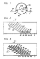
- a rotary head assembly of an 8 mm video tape recorder includes recording and reproducing rotary magnetic heads HA and HB. These rotary magnetic heads HA and HB have gaps with different azimuth angles and are mounted on a rotary drum 1 with an angular spacing of 180 0 therebetween.
- the rotary heads HA and HB are rotated at a rotational speed equal to the standard frame frequency (30 Hz for the NTSC standard) in the direction indicated by an arrow 3H and protrude slightly from the peripheral surface of the rotary drum 1.
- a magnetic tape 2 is wrapped around the peripheral surface of the rotary drum 1 over an angular extent of 221 and is suitably transported at a constant speed in the direction indicated by an arrow 3T.
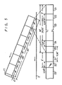
- tracks 4A and 4B are alternately formed on the tape 2 by the rotary heads HA and HB, respectively.
- overscan area AP of each track having an angular extent of 36° measured from a point at which the rotary heads HA and HB start scanning the tracks 4A and 4B, there is recorded an audio signal corresponding to one field period of the video signal and which has been pulse-code modulated and time compressed.
- each track having an angular extent of 180° there are respectively recorded a colour video signal of one field period, an FM (frequency modulated) audio signal of one field and tracking pilot signals.
- the remaining area of each track which has an angular extent of 5° is assigned as a spare area in which the head is disengaged from the tape.
- a PCM audio signal can be recorded and reproduced by an 8 mm video tape recorder in a so-called "audio-use" mode in which, as disclosed in detail in U.S. Patent No. US-A-4 542 419, the main recording area AV of each track is also used for recording the PCM audio signal.
- the 8 mm video tape recorder becomes a PCM audio signal recording and/or reproducing apparatus in which PCM audio signals can be recorded in multiple channels.
- each track corresponding to the angular range of 180° is divided equally into five portions and the PCM audio signal is recorded in a selected one of these divided portions during scanning of each track. Therefore, the whole area of each track shown in Figure 2, including the area AP and the area AV, is divided into six track areas API to AP6, each corresponding to an angular range or extent of 36°, and first to sixth track channels are formed by the same numbered segments or track areas API to AP6 of the respective skewed or slant tracks 4A,4B,4A, 4B, etc.
- the PCM audio signal may be recorded first in the segments or track areas AP1 of the successive tracks 4A,4B from one end of the tape to the other. Thereafter, the PCM audio signal may be further recorded in segments or track areas AP2 of the successive tracks from one end of the tape to the other. Accordingly, PCM audio signals can be recorded in and reproduced from each of the six channels with the result that, in the audio-use or multi-PCM mode shown in Figure 3, the tape 2 has a recording time or capacity six times as long as when a PCM audio signal is recorded only in the overscan area AP of each track, as in Figure 2.
- the PCM signal processing circuit used therefor may be the signal processing circuit provided for processing the PCM audio signal recorded in the single channel constituted by the track areas AP in the previously-proposed 8 mm video tape recorder.
- a PCM data recording area 13 having an angular extent of 26.32° and in which a time compressed PCM audio signal is recorded.
- a postamble area 14 also having an angular extent of 2.06° (3H) follows the PCM data recording area 13 so as to be used as a back margin area to cope with the displacement of the recording position when the recording is carried out in the so-called after-recording mode.
- an area having an angular extent of 2.62° is assigned as a guard band area 15 for separating a subsequent video signal recording area 16 from the PCM data area 13.
- the video recording area 16 has an angular range of 180 0 (as noted earlier) for receiving the recorded video signal of one field period.
- a head disengaging area 17 having an angular extent of 5° and in which the rotary head is disengaged freely from the magnetic tape.
- each segment track area in Figure 5 is formed of a tracing starting area 21, a preamble area 22, a PCM data area 23, a postamble area 24 and a guard band area 25.
- the same format is assigned to each of the segment track areas AP1 to AP6 shown in Figure 3.
- the PCM data is recorded on the tape with binary code data having a logic level "1" or “0” being modulated as signals of respective frequencies.
- data having the logic level “1” is modulated to or represented by a recorded signal having a frequency of 5.8 MHz
- data having the logic level "0” is modulated to or represented by a recorded signal having a frequency 2.9 MHz.
- data having the logic level "1" was recorded in each premable area 12 or 22 and in each postamble area 14 or 24.
- an area specifying signal for identifying the postamble area as the area receiving the index signal is generated, whereby the index signal can be recorded, or the recorded index signal can be erased, within such area specified by the area specifying signal.
- an index signal can be recorded or erased by the rotary head or heads so that a special stationary head for the index signal is not required. Further, since the index signal is recorded in an area separated from the track areas for recording of the PCM data and the video signal, it is possible to insert or erase the index signal in the after-recording mode.
- the tape speed can be selected to be either a first tape speed for SP (short play) or a second tape speed (which is half the first tape speed) for LP (long play) mode.
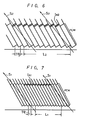
- Figures 6 and 7 of the accompanying drawings illustrate typical recording track patterns for the SP mode and the LP mode, respectively, at the portions of the tracks near to the PCM areas indicated at AP in Figure 2.
- the hatched areas each represent a postamble area 14 or 24 ( Figures 4 and 5) into which the index signal is inserted or recorded, that is, the index area. It will be clear from a comparison of Figures 6 and 7 that the recording track pitch TP 1 in the LP mode is substantially smaller than the recording track pitch TP 2 in the SP mode.
- the index signal When the index signal is inserted in the after-recording mode or erased, the index signal is recorded in, or erased from, the respective area of each track during a predetermined time period as mentioned before, and as indicated by the hatched areas I A1 and I A2 in Figures 7 and 6, respectively. If the index signal is inserted or recorded in such areas IA2 and I A1 during the same periods in the SP and LP modes, respectively, it will be clear from Figures 6 and 7 that the length L 1 along the tape occupied by tracks having the index signal inserted in the LP mode is shorter than, for example, one-half the length L 2 along the tape occupied by tracks having the index signal inserted in the SP mode.
- apparatus for recording and/or reproducing an additional information signal on a magnetic record medium having video and audio signals recorded thereon in oblique tracks with the recorded audio signal being arranged in an extended end portion of each of said oblique tracks and with the pitch of said oblique tracks being different for different recording modes, said apparatus comprising:
- a preferred embodiment of this invention provides an improved apparatus for recording and/or reproducing an additional information signal, such as the index signal mentioned above, and which can avoid the problems previously mentioned.
- the preferred apparatus has SP and LP modes for recording and/or reproducing the information signal and the index signal, and when the apparatus is used in an 8 mm video tape recorder mode with the recording track pitch characteristic of the LP mode, the index signal is inserted for a time period longer than that employed in the SP mode.
- Such apparatus can positively and easily carry out a program search for accessing, with reference to the index signal, a starting point of an event in the information signal recorded in oblique tracks on a tape.
- the preferred embodiment provides helical scan apparatus having a rotary head or heads for recording and/or reproducing video and audio signals in oblique tracks on a magnetic tape with the recorded audio signals being recorded in overscan areas of the oblique tracks and with the pitch of the tracks being different as a result of changes in the tape speed for different recording modes.
- Index signals are recorded by the rotary head or heads at predetermined positions in the overscan areas of a plurality of the oblique tracks for a period of time dependent upon the recording mode previously used for recording the video and audio signals. Therefore, in a program search operation employing high speed playback, the index signals can be extracted from the output of the rotary head or heads for identifying a respective program or event irrespective of the recording mode in which the video and audio signals were recorded.
- FIG 8 there is shown an apparatus according to an embodiment of this invention for recording and/or reproducing video and PCM audio signals and also an additional information signal, for example, an index signal, with the position or area in which the index signal is recorded being determined by an area signal generated from address data included in the PCM data.
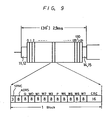
- the PCM data for each track is arranged so that an information signal, such as the audio signal or the like corresponding to a field period, is divided into a plurality of blocks and a block synchronising signal and a block address signal are added to each of the divided blocks.
- the PCM audio data of each track is formed of 132 blocks and each block is formed of a block synchronizing signal SYNC of 3 bits, a block address word ADRS of 8 bits, error correction parity words P and Q of 8 bits each, audio data words WO to W7 each of 8 bits, and an error detection CRC (cyclic redundancy check) code of 16 bits.
- the CRC code is generated for the words of the respective block from the address word ADRS up to the data word W7.
- the address word ADRS indicates the sequential order (block number) of the block with respect to the block data for one track. Accordingly, the data of each block address indicate an absolute address or position of the PCM audio track recorded on the tape. This absolute address or position is not changed even if the track pattern is formed with a different timing. Therefore, in the embodiment of the invention to be described below with reference to Figure 8, the block address data in the PCM data is detected and an index area specifying signal is formed on the basis of this block address data.
- the apparatus shown therein includes recording and/or reproducing change-over switching circuits 31A and 31B to which a recording or reproducing switching signal SM from a terminal 41 is applied through an OR gate 42.
- Each of the switching circuits 31A and 31B engages a recording terminal REC upon recording and is changed-over to engage a playback terminal PB upon reproducing.
- Rotary head change-over switching circuits 32 and 33 are operated by a head switching signal RFSW to be alternately disposed in the positions shown in full lines and in dotted lines respectively, at every 1/2 revolution of the rotary recording/reproducing heads HA and HB.
- a switch 34 is provided to select the timing of the switching signal RFSW for a normal mode and a multi-PCM mode, respectively. More specifically, for the normal mode, the movable contact of the switch 34 is engaged with a terminal N, at which time a pulse PG having a frequency of 30 Hz which is generated from a pulse generator 43, and is indicative of the absolute rotary phase of the rotary heads HA and HB, is supplied to a switching signal generating circuit 44 from which a square wave signal SC having a duty ratio of 50% is derived. This square wave signal SC is supplied unchanged via the switch 34 to the switching circuits 32 and 33 as the switching signal RFSW.
- the suitably phase-shifted signal from the circuit 45 is supplied via the switch 34 to the switching circuits 32 and 33 as the switching signal RFSW for the multi-PCM mode.
- the switching signal RFSW is also supplied to a PCM audio signal processor 62 included in a PCM signal system 60 and which generates a PCM area signal indicative of the specified one of the segment track areas API-AP6.
- An input video signal applied to an input terminal 51 is supplied to a video signal system 50 in which it is suitably processed.
- the output signal from the video signal system 50 is then supplied to the switching circuit 32.
- the switching circuit 32 With the switch 34 engaging its contact N for selecting the normal PCM mode, the switching circuit 32 is alternatively switched by the switching signal RFSW at every half revolution of the rotary heads HA and HB, which are controlled by a drum phase servo taking the pulse PG as a reference phase so that when the rotary head HA scans the area AV of a track 4A (described before in connection with Figures 2 and 4), the video signal is supplied through a recording amplifier 46A and the switching circuit 31A to the rotary head HA, and is thereby recorded on this area AV of the respective track 4A.
- the video signal is supplied through a recording amplifier 46B and the switching circuit 31B to the rotary head HB, and is . thereby recorded on the area AV of the respective track 4B.
- the audio signal is digitised, the resulting digital signal is divided into 132 blocks for each field period thereof, the parity words P and Q, each of which is an error correction code, are generated, and the CRC code is generated for each block. Then, the data of one field period is time compressed to about 1/5 its original duration by a PCM area signal formed on the basis of the switching signal RFSW, the block synchronising signal SYNC and the block address signal ADRS are added to each block, each block is formed as the data series shown in Figure 9 and this block is read as one of the blocks in the sequence shown in Figure 9.
- the PCM data thus read are modulated to a signal having a frequency of 5.8 MHz when the data is "I”, and to a signal having a frequency of 2.9 MHz when the data is "0".
- the modulated signal is supplied from the PCM audio signal processor 62 through the switching circuit 35, whereby, in response to the changing-over of the switching circuit 32 by the switching signal RFSW, the modulated PCM audio signal is recorded in the area AP of a track 4A by the rotary head HA and in the area AP of a track 4B by the rotary head HB, as shown in Figure 2.
- the movable contact of the switch 34 is engaged with its contact M, thereby to allow the phase shifter circuit 45 to generate a head switching signal RFSW whose phase is shifted by a whole multiple of 36° in accordance with a specified PCM area, and from which a PCM area specifying signal is derived. Accordingly, the PCM audio signal is recorded in a specified one of the segment track areas AP1 to AP6, as shown in Figure 5.
- the reproducing mode of the apparatus will now be described.
- the rotary phase of the rotary drum is again servo-controlled on the basis of the pulse signal PG generated from the pulse generator 43.
- tracking pilot signals (not shown) of a so-called four frequency system are cyclically recorded on each of the tracks 4A and 4B so that, during reproducing, tracking servo is effected with reference to the four frequency system tracking pilot signals.
- the 8 mm video tape recorder is also shown in Figure 8 to be provided with an erase rotary head FE, having a gap width about twice the gap width of the rotary heads HA and HB.
- the reproduced output from this erase rotary head FE is supplied to a pilot signal extracting circuit 91 which extracts a pilot signal component.
- the resulting pilot signal component is supplied to a mode judging circuit 92 which determines therefrom whether the recording track being played back is in accordance with the SP mode or the LP mode.
- a technique for judging whether a track was recorded in the SP mode or the LP mode by using the pilot signal component in the reproduced output from the erase rotary head FE is disclosed in Japanese Patent Application No. 87636/1984. This previously-proposed technique utilises the fact that the track pitch in the SP mode is different from the track pitch in the LP mode, so that the pilot signal components contained in the reproduced output played back by the erase rotary head FE are different in the respective modes.
- the output MJ from the mode judging circuit 92 is supplied to a system controller (not shown) by which the tape speed in the playback mode is made equal to that in the recording mode.
- the reproduced signal outputs from the rotary heads HA and HB are respectively supplied through playback amplifiers 47A and 47B to the switching circuit 33.
- the switching circuit 33 is changed-over in response to the switching signal RFSW, so that the video signal from the area AV of each track is supplied to the video signal system 50, and the PCM data from the area AP of each track is supplied to the PCM signal system 60.
- the video signal is demodulated and then delivered to an output terminal 52.
- the reproduced PCM data is supplied through a playback equaliser circuit 63 and a limiter circuit 64 to a bit synchronising circuit 65.
- This bit synchronising circuit 65 is formed of a D-type flip-flop circuit 66 and a PLL (phase locked loop) circuit 67. From the D-type flip-flop circuit 66, there is derived the data "1" or "0" modulated as mentioned before. The resulting data is supplied to the PCM audio signal processor 62 in which it is error detected, error corrected and subjected to other processing, and thereafter it is re-converted into left and right channel analog audio signals. These left and right channel analog audio signals are provided at output terminals 68L and 68R, respectively.
- the switching circuit 35 is changed over from its normal position engaging contact N to a position engaging a contact I dx during scanning of an index area. Further, a switching circuit 36 is operable to apply selectively to the contact I dx either an index signal or an erasing signal in response to a switching signal SW when the index signal is respectively inserted or erased.
- the index signal is a single tone signal having a frequency of 2.9 MHz and which is generated by an oscillator 71.
- the erasing signal is a single tone signal having a frequency of 5.8 MHz, and which is provided by an oscillator 72.
- a circuit 80 is provided for generating an index area specifying signal.
- the index area specifying signal is generated by the generating circuit 80, as follows.
- Reproduced data Sl (as shown in Figures 10A and 10B) which is bit- synchronised and derived from the D-type flip-flop circuit 66 in the PCM signal system 60 is supplied to a demodulating circuit 81 and to a block synchronising signal detecting circuit 82 in the generating circuit 80.
- the block synchronising signal SYNC is detected in the circuit 82, the latter generates a latch pulse S2 ( Figure 10C) at a time corresponding to the last bit of the address data ADRS demodulated by the demodulating circuit 81.
- the address data ADRS of 8 bits is latched in a latch circuit 83 by the latch pulse S2.
- a latch output S3 ( Figure 10D) is supplied to a preset terminal of a counter 85.
- the data demodulated by the demodulator 81 is also supplied to an error detection circuit 84 in which any error in each block can be detected through the use of the CRC code. Since the CRC code is generated for the words including the address data ADRS upon recording, if the address data ADRS has an error, such error of the address data ADRS will be detected.
- the latch pulse S2 from the block synchronising signal detecting circuit 82 is also supplied to the error detection circuit 84 as a calculation start pulse, and the calculation for error detection is initiated thereby.
- the circuit 84 When an absence of error is detected by the circuit 84, the latter generates a pulse S4 ( Figure 10E).
- the counter 85 is loaded by this pulse S4 with the address value from the latch circuit 83 which is preset in the counter 85.
- a clock pulse of one block period is supplied to the counter 85 from a clock generator 86. Accordingly, once the counter 85 has been loaded and preset with the address value from the latch circuit 83, even if the following data are all erroneous, the counter 85 increments from its preset value at every data block in response to the clock pulse from the generator 86. Needless to say, if a data block does not contain any error, the pulse S4 is generated by the error detection circuit 84 in response to each such block so that the address data ADRS is preset in the counter 85 for each block. At such time, the clock pulse is ignored by the counter 85.
- a counted value S5 ( Figure 10F) from the counter 85 is supplied to a decoder 87 which detects when the counter value .55 becomes the last address of the data block, that is, the address 131, and then generates a detection pulse S6 ( Figure 10G).
- a monostable multivibrator 88 is triggered by the detection pulse 56 to provide an index area signal S7 ( Figure 10H).
- the decoder 87 generates the detection pulse S6 when the counted value S5 of the counter 85 becomes, for example, "133" (taking a spare into consideration), rather than "131".
- the obtained index area signal S7 is supplied through a gate circuit 94 to the switching circuit 35 as a switching signal for the latter so that the switching circuit 35 is changed over from the contact N (connected to the PCM audio signal processor 62) to the contact I dx (connected to the switching circuit 36).
- the index area signal S7 passed through the gate circuit 94 is also supplied through the OR gate 42 as a switching signal for recording and/or reproducing the change-over switching circuits 31A and 31B with the result that, during the scanning of each index area, the switching circuits 31A and 31B are engaged with the respective recording terminals REC.
- the switching circuit 36 when the index signal is to be inserted or recorded, the switching circuit 36 is in the illustrated position, and the index signal having a frequency of 2.9 MHz is recorded on a track being scanned in its postamble area specified by the index area S7.
- the switching circuit 36 in the erasing mode, that is when a previously recorded index signal is to be erased, the switching circuit 36 is changed over to the position opposite to that illustrated so that the erasing signal having a frequency of 5.8 MHz is supplied to the head HA or HB during the period specified by the index area signal S7, and the previously recorded index signal is erased thereby.
- the gate circuit 94 controls the length of time during which the index area signals S7 are allowed to pass therethrough for recording or inserting i index signals or erasing previously recorded index signals.
- the gate circuit 94 may be suitably controlled, for example, by a gating signal GT from an insertion time generating circuit 93.
- This insertion time generating circuit 93 is supplied with the SP/LP mode judging signal MJ from the mode judging circuit 92 and which controls a switch 95.
- the resulting gating signal GT from the circuit 93 opens the gate circuit 94 for a predetermined time period which is, for example, twice as long as the period during which the gating signal GT opens the gate circuit 94 if the switch 95 is OFF or opened.
- the switch 95 is closed in response to the signal MJ indicating the LP mode, so that the gate circuit 94 is opened for a time period which is twice that when the mode judging signal MJ indicates the SP mode.
- the gate circuit 94 is opened by the gating signal GT for 3 seconds
- the gate circuit 94 is opened for 6 seconds by the gating signal GT.
- each index area signal S7 is passed through the gate circuit 94, whereby, as mentioned before, the index signal is recorded in the respective index area or the recorded index signal is erased therefrom.
- the multi-PCM mode by changing over the switching circuit 34 from the contact N to the contact M, it is possible to record or erase an index signal in an area suitably identified by the index area signal S7 in a manner similar to that described above.
- the recording mode signal SM applied to the terminal 41 is also supplied to the insertion time generating circuit 93, whereby, in the recording mode, the gate circuit 94 is maintained open by the output signal GT from the generating circuit 93. Therefore, in the recording mode, and in response to the switched state of the switching circuit 36, an index signal having a frequency of 2.9 MHz or a postamble signal having a frequency of 5.8 MHz is recorded in the postamble area.
- the postamble signal has a frequency of 5.8 MHz, which also represents the binary code signal of "1" so that the frequency of 2.9 MHz is used for the index signal
- the index signal is not limited thereto, and a signal having a pattern which does not appear as data may be used instead.
- coding data as the index signal. If the coding is carried out as described above, it is possible to record, in addition to data indicative of the starting point of, for example, a piece of music, data indicative of an intermediate portion of the piece of music, and other data, such as data representing tape speed, time information and the like, as the index signal.
- this invention is not limited to apparatus for recording and/or reproducing a PCM audio signal but can be applied to other apparatus for recording and/or reproducing various other kinds of information.
- the index signal is inserted or recorded for periods of time that correspond to the different track pitches so that, in the high speed search mode, the index signal can be satisfactorily picked up or detected with either track pitch.
Abstract
Description
- This invention relates to apparatus for recording and/or reproducing an additional information signal. Such apparatus may be suitable for use with helical scan apparatus for recording and/or reproducing a PCM (pulse-code modulated) audio signal by a rotary head. More particularly, the apparatus may be arranged to record an index signal in a recorded track, such as a signal indicative of a starting point of a recorded event, in a so-called after-recording mode, or to erase such an index signal.
- An 8 mm video tape recorder can be used in a normal recording mode in which an audio signal is frequency modulated prior to being mixed with a colour video signal and then recorded in such a way that the audio signal can be frequency separated from the colour video signal upon playback, and also in an optional recording mode in which the audio signal is pulse-code modulated and recorded in a so-called overscan area which is separate from the main area of each oblique track in which the colour video signal is recorded.
- As is shown in Figure 1 of the accompanying drawings, a rotary head assembly of an 8 mm video tape recorder includes recording and reproducing rotary magnetic heads HA and HB. These rotary magnetic heads HA and HB have gaps with different azimuth angles and are mounted on a
rotary drum 1 with an angular spacing of 1800 therebetween. The rotary heads HA and HB are rotated at a rotational speed equal to the standard frame frequency (30 Hz for the NTSC standard) in the direction indicated by anarrow 3H and protrude slightly from the peripheral surface of therotary drum 1. Amagnetic tape 2 is wrapped around the peripheral surface of therotary drum 1 over an angular extent of 221 and is suitably transported at a constant speed in the direction indicated by anarrow 3T. - Accordingly, as shown in Figure 2 of the accompanying drawings,
tracks drum 1, are alternately formed on thetape 2 by the rotary heads HA and HB, respectively. In a so-called overscan area AP of each track having an angular extent of 36° measured from a point at which the rotary heads HA and HB start scanning thetracks - Furthermore, a PCM audio signal can be recorded and reproduced by an 8 mm video tape recorder in a so-called "audio-use" mode in which, as disclosed in detail in U.S. Patent No. US-A-4 542 419, the main recording area AV of each track is also used for recording the PCM audio signal. In such audio-use or multi-PCM mode, the 8 mm video tape recorder becomes a PCM audio signal recording and/or reproducing apparatus in which PCM audio signals can be recorded in multiple channels. More specifically, as shown in Figure 3 of the accompanying drawings, in the audio-use or multi-PCM mode, the area A of each track corresponding to the angular range of 180° is divided equally into five portions and the PCM audio signal is recorded in a selected one of these divided portions during scanning of each track. Therefore, the whole area of each track shown in Figure 2, including the area AP and the area AV, is divided into six track areas API to AP6, each corresponding to an angular range or extent of 36°, and first to sixth track channels are formed by the same numbered segments or track areas API to AP6 of the respective skewed or
slant tracks successive tracks tape 2 has a recording time or capacity six times as long as when a PCM audio signal is recorded only in the overscan area AP of each track, as in Figure 2. - In the case of the multi-PCM mode, if recording and/or reproducing is effected in or from each segment track area, the PCM signal processing circuit used therefor may be the signal processing circuit provided for processing the PCM audio signal recorded in the single channel constituted by the track areas AP in the previously-proposed 8 mm video tape recorder.
- The track format of the above-mentioned 8 mm video tape recorder will now be described more fully with reference to Figure 4 of the accompanying drawings, in which contact of the rotary head with the
tape 2, that is, the starting point of the track, begins at the right-hand side where there is provided atracing starting area 11 corresponding, in extent, to a 5° rotation angle of a rotary head. At the rear ortrailing portion 12 of thetracing starting area 11, a period having an angular range or extent of 2.06° and corresponding to 3H of the video signal (where H is the horizontal period) is assigned as a preamble area which will become a clock run-in area synchronised with the succeeding PCM data. Following the clock run-inarea 12, there is provided a PCMdata recording area 13 having an angular extent of 26.32° and in which a time compressed PCM audio signal is recorded. Apostamble area 14 also having an angular extent of 2.06° (3H) follows the PCMdata recording area 13 so as to be used as a back margin area to cope with the displacement of the recording position when the recording is carried out in the so-called after-recording mode. Next an area having an angular extent of 2.62° is assigned as aguard band area 15 for separating a subsequent videosignal recording area 16 from thePCM data area 13. Thevideo recording area 16 has an angular range of 1800 (as noted earlier) for receiving the recorded video signal of one field period. Next to thearea 16, there is provided ahead disengaging area 17 having an angular extent of 5° and in which the rotary head is disengaged freely from the magnetic tape. - A track format used in the multi-PCM mode will now be described with reference to Figure 5 of the accompanying drawings, in which it is shown that the format for each segment track area for the PCM audio signal is exactly the same as the format for the PCM audio area used in the normal 8 mm video tape recorder. Thus, each segment track area in Figure 5 is formed of a
tracing starting area 21, apreamble area 22, aPCM data area 23, apostamble area 24 and aguard band area 25. The same format is assigned to each of the segment track areas AP1 to AP6 shown in Figure 3. - Generally, the PCM data is recorded on the tape with binary code data having a logic level "1" or "0" being modulated as signals of respective frequencies. In the 8 mm video tape recorder, for example, data having the logic level "1" is modulated to or represented by a recorded signal having a frequency of 5.8 MHz, while data having the logic level "0" is modulated to or represented by a recorded signal having a frequency 2.9 MHz. Previously, only data having the logic level "1", that is, a signal having the frequency 5.8 MHz, was recorded in each
premable area postamble area - A so-called program search method for locating a starting point of a recorded event in the 8 mm video tape recorder mode and the multi-PCM mode has been proposed in US Patent Application Serial No. 838 626, filed on 11 March, 1986. In accordance with this proposal, an index signal is recorded in, for example, the
postamble area - In accordance with the above described proposal, an index signal can be recorded or erased by the rotary head or heads so that a special stationary head for the index signal is not required. Further, since the index signal is recorded in an area separated from the track areas for recording of the PCM data and the video signal, it is possible to insert or erase the index signal in the after-recording mode.
- It is further to be noted that, in the 8 mm video tape recorder, the tape speed can be selected to be either a first tape speed for SP (short play) or a second tape speed (which is half the first tape speed) for LP (long play) mode.
- Figures 6 and 7 of the accompanying drawings illustrate typical recording track patterns for the SP mode and the LP mode, respectively, at the portions of the tracks near to the PCM areas indicated at AP in Figure 2. In Figures 6 and 7, the hatched areas each represent a
postamble area 14 or 24 (Figures 4 and 5) into which the index signal is inserted or recorded, that is, the index area. It will be clear from a comparison of Figures 6 and 7 that the recording track pitch TP1 in the LP mode is substantially smaller than the recording track pitch TP2 in the SP mode. - When the index signal is inserted in the after-recording mode or erased, the index signal is recorded in, or erased from, the respective area of each track during a predetermined time period as mentioned before, and as indicated by the hatched areas IA1 and IA2 in Figures 7 and 6, respectively. If the index signal is inserted or recorded in such areas IA2 and IA1 during the same periods in the SP and LP modes, respectively, it will be clear from Figures 6 and 7 that the length L1 along the tape occupied by tracks having the index signal inserted in the LP mode is shorter than, for example, one-half the length L2 along the tape occupied by tracks having the index signal inserted in the SP mode.
- As a result of the above, when the starting point of a recorded event on the slant track is accessed in the high speed search mode and the tape speed used in the high speed search mode is the same whether the event was recorded in the SP mode or in the LP mode, there is the possibility that the rotary heads HA and HB in obliquely scanning the tracks, as shown by arrows S2 and SI in Figures 6 and 7, will pick up the index signal in the SP mode, but not in the LP mode.
- According to the present invention there is provided apparatus for recording and/or reproducing an additional information signal on a magnetic record medium having video and audio signals recorded thereon in oblique tracks with the recorded audio signal being arranged in an extended end portion of each of said oblique tracks and with the pitch of said oblique tracks being different for different recording modes, said apparatus comprising:
- reproducing means for reproducing said video and audio signals;
- means for detecting the one of said different recording modes used for recording said magnetic record medium;
- means for generating index signals;
- means for generating index area signals;
- means for generating a recording period signal according to said one of the recording modes detected by said recording mode detecting means; recording means for recording said index signals; and
- control means for controlling said recording means to record said index signals at positions determined by said index area signals in said extended end portions of a plurality of said oblique tracks in series during a time period determined by said recording period signal.
- A preferred embodiment of this invention provides an improved apparatus for recording and/or reproducing an additional information signal, such as the index signal mentioned above, and which can avoid the problems previously mentioned.
- The preferred apparatus has SP and LP modes for recording and/or reproducing the information signal and the index signal, and when the apparatus is used in an 8 mm video tape recorder mode with the recording track pitch characteristic of the LP mode, the index signal is inserted for a time period longer than that employed in the SP mode. Such apparatus can positively and easily carry out a program search for accessing, with reference to the index signal, a starting point of an event in the information signal recorded in oblique tracks on a tape.
- The preferred embodiment provides helical scan apparatus having a rotary head or heads for recording and/or reproducing video and audio signals in oblique tracks on a magnetic tape with the recorded audio signals being recorded in overscan areas of the oblique tracks and with the pitch of the tracks being different as a result of changes in the tape speed for different recording modes. Index signals are recorded by the rotary head or heads at predetermined positions in the overscan areas of a plurality of the oblique tracks for a period of time dependent upon the recording mode previously used for recording the video and audio signals. Therefore, in a program search operation employing high speed playback, the index signals can be extracted from the output of the rotary head or heads for identifying a respective program or event irrespective of the recording mode in which the video and audio signals were recorded.
- The invention will now be described by way of example with reference to the accompanying drawings, throughout which like parts are referred to by like references, and in which:
- Figure 1 is a schematic diagram showing one example of a rotary head assembly of a known 8 mm video tape recorder to which the present invention may be applied;
- Figures 2 and 3 are schematic diagrams showing recording track patterns formed by the rotary head assembly of Figure 1 for different recording modes thereof;
- Figures 4 and 5 are schematic diagrams showing tracks formats respectively used in the recording modes of Figures 2 and 3;
- Figures 6 and 7 are schematic diagrams to which reference is made in explaining the relationship between tape speed and the track pattern in the recording mode;
- Figure 8 is a block diagram showing an apparatus for recording and/or reproducing an additional information or index signal according to an embodiment of this invention;
- Figure 9 is a schematic diagram to which reference will be made in explaining the arrangement of the PCM data; and
- Figures 10A to 10H are timing charts to which reference will be made in explaining the operation of the apparatus of Figure 8.
- In Figure 8, there is shown an apparatus according to an embodiment of this invention for recording and/or reproducing video and PCM audio signals and also an additional information signal, for example, an index signal, with the position or area in which the index signal is recorded being determined by an area signal generated from address data included in the PCM data. More particularly, the PCM data for each track is arranged so that an information signal, such as the audio signal or the like corresponding to a field period, is divided into a plurality of blocks and a block synchronising signal and a block address signal are added to each of the divided blocks.
- In the case of an 8 mm video tape recorder, as shown in Figure 9, the PCM audio data of each track is formed of 132 blocks and each block is formed of a block synchronizing signal SYNC of 3 bits, a block address word ADRS of 8 bits, error correction parity words P and Q of 8 bits each, audio data words WO to W7 each of 8 bits, and an error detection CRC (cyclic redundancy check) code of 16 bits. The CRC code is generated for the words of the respective block from the address word ADRS up to the data word W7.
- The address word ADRS indicates the sequential order (block number) of the block with respect to the block data for one track. Accordingly, the data of each block address indicate an absolute address or position of the PCM audio track recorded on the tape. This absolute address or position is not changed even if the track pattern is formed with a different timing. Therefore, in the embodiment of the invention to be described below with reference to Figure 8, the block address data in the PCM data is detected and an index area specifying signal is formed on the basis of this block address data.
- Referring in detail to Figure 8, it will be seen that the apparatus shown therein (for recording and/or reproducing video and PCM audio signals and an additional information signal) includes recording and/or reproducing change-over
switching circuits 31A and 31B to which a recording or reproducing switching signal SM from a terminal 41 is applied through anOR gate 42. Each of the switchingcircuits 31A and 31B engages a recording terminal REC upon recording and is changed-over to engage a playback terminal PB upon reproducing. - Rotary head change-over
switching circuits - A
switch 34 is provided to select the timing of the switching signal RFSW for a normal mode and a multi-PCM mode, respectively. More specifically, for the normal mode, the movable contact of theswitch 34 is engaged with a terminal N, at which time a pulse PG having a frequency of 30 Hz which is generated from apulse generator 43, and is indicative of the absolute rotary phase of the rotary heads HA and HB, is supplied to a switching signal generating circuit 44 from which a square wave signal SC having a duty ratio of 50% is derived. This square wave signal SC is supplied unchanged via theswitch 34 to the switchingcircuits - For the multi-PCM mode, the movable contact of the
switch 34 engages a terminal M so that, at that time, the square wave signal SC from the switching signal generating circuit 44 is supplied through aphase shifter circuit 45 by which, in accordance with the segment track area specified, the square wave signal SC is phase-shifted by 36° x (n-1), in which n is an integer corresponding to the segment track area number, for example n=1 for the segment track area API, n=2 for AP2, ..... n=6 for AP6. The suitably phase-shifted signal from thecircuit 45 is supplied via theswitch 34 to the switchingcircuits audio signal processor 62 included in aPCM signal system 60 and which generates a PCM area signal indicative of the specified one of the segment track areas API-AP6. - The recording mode of the apparatus of Figure 8 will now be described. An input video signal applied to an input terminal 51 is supplied to a
video signal system 50 in which it is suitably processed. The output signal from thevideo signal system 50 is then supplied to the switchingcircuit 32. With theswitch 34 engaging its contact N for selecting the normal PCM mode, the switchingcircuit 32 is alternatively switched by the switching signal RFSW at every half revolution of the rotary heads HA and HB, which are controlled by a drum phase servo taking the pulse PG as a reference phase so that when the rotary head HA scans the area AV of atrack 4A (described before in connection with Figures 2 and 4), the video signal is supplied through arecording amplifier 46A and theswitching circuit 31A to the rotary head HA, and is thereby recorded on this area AV of therespective track 4A. In like manner, when the rotary head HB scans the area AV of a track 48, the video signal is supplied through arecording amplifier 46B and the switching circuit 31B to the rotary head HB, and is . thereby recorded on the area AV of therespective track 4B. - Left and right channel audio signals applied to input
terminals audio signal processor 62 and are processed therein to form PCM data. - In other words, the audio signal is digitised, the resulting digital signal is divided into 132 blocks for each field period thereof, the parity words P and Q, each of which is an error correction code, are generated, and the CRC code is generated for each block. Then, the data of one field period is time compressed to about 1/5 its original duration by a PCM area signal formed on the basis of the switching signal RFSW, the block synchronising signal SYNC and the block address signal ADRS are added to each block, each block is formed as the data series shown in Figure 9 and this block is read as one of the blocks in the sequence shown in Figure 9. The PCM data thus read are modulated to a signal having a frequency of 5.8 MHz when the data is "I", and to a signal having a frequency of 2.9 MHz when the data is "0". The modulated signal is supplied from the PCM
audio signal processor 62 through the switchingcircuit 35, whereby, in response to the changing-over of the switchingcircuit 32 by the switching signal RFSW, the modulated PCM audio signal is recorded in the area AP of atrack 4A by the rotary head HA and in the area AP of atrack 4B by the rotary head HB, as shown in Figure 2. - In the multi-PCM mode, the movable contact of the
switch 34 is engaged with its contact M, thereby to allow thephase shifter circuit 45 to generate a head switching signal RFSW whose phase is shifted by a whole multiple of 36° in accordance with a specified PCM area, and from which a PCM area specifying signal is derived. Accordingly, the PCM audio signal is recorded in a specified one of the segment track areas AP1 to AP6, as shown in Figure 5. - The reproducing mode of the apparatus will now be described. In the reproducing or playback mode, the rotary phase of the rotary drum is again servo-controlled on the basis of the pulse signal PG generated from the
pulse generator 43. - In the case of the 8 mm video tape recorder, tracking pilot signals (not shown) of a so-called four frequency system are cyclically recorded on each of the
tracks - The 8 mm video tape recorder is also shown in Figure 8 to be provided with an erase rotary head FE, having a gap width about twice the gap width of the rotary heads HA and HB. In the playback mode, the reproduced output from this erase rotary head FE is supplied to a pilot
signal extracting circuit 91 which extracts a pilot signal component. The resulting pilot signal component is supplied to a mode judging circuit 92 which determines therefrom whether the recording track being played back is in accordance with the SP mode or the LP mode. A technique for judging whether a track was recorded in the SP mode or the LP mode by using the pilot signal component in the reproduced output from the erase rotary head FE is disclosed in Japanese Patent Application No. 87636/1984. This previously-proposed technique utilises the fact that the track pitch in the SP mode is different from the track pitch in the LP mode, so that the pilot signal components contained in the reproduced output played back by the erase rotary head FE are different in the respective modes. - The output MJ from the mode judging circuit 92 is supplied to a system controller (not shown) by which the tape speed in the playback mode is made equal to that in the recording mode.
- In the playback mode, the reproduced signal outputs from the rotary heads HA and HB are respectively supplied through
playback amplifiers circuit 33. The switchingcircuit 33 is changed-over in response to the switching signal RFSW, so that the video signal from the area AV of each track is supplied to thevideo signal system 50, and the PCM data from the area AP of each track is supplied to thePCM signal system 60. - In the
video signal system 50, the video signal is demodulated and then delivered to anoutput terminal 52. - On the other hand, in the
PCM signal system 60, the reproduced PCM data is supplied through aplayback equaliser circuit 63 and alimiter circuit 64 to abit synchronising circuit 65. Thisbit synchronising circuit 65 is formed of a D-type flip-flop circuit 66 and a PLL (phase locked loop)circuit 67. From the D-type flip-flop circuit 66, there is derived the data "1" or "0" modulated as mentioned before. The resulting data is supplied to the PCMaudio signal processor 62 in which it is error detected, error corrected and subjected to other processing, and thereafter it is re-converted into left and right channel analog audio signals. These left and right channel analog audio signals are provided atoutput terminals - The switching
circuit 35 is changed over from its normal position engaging contact N to a position engaging a contact Idx during scanning of an index area. Further, a switchingcircuit 36 is operable to apply selectively to the contact Idx either an index signal or an erasing signal in response to a switching signal SW when the index signal is respectively inserted or erased. - In the case of the illustrated example, the index signal is a single tone signal having a frequency of 2.9 MHz and which is generated by an oscillator 71. Further, in the illustrated example, the erasing signal is a single tone signal having a frequency of 5.8 MHz, and which is provided by an oscillator 72.
- A
circuit 80 is provided for generating an index area specifying signal. When the index signal is written in thepostamble area circuit 80, as follows. - Reproduced data Sl (as shown in Figures 10A and 10B) which is bit- synchronised and derived from the D-type flip-
flop circuit 66 in thePCM signal system 60 is supplied to ademodulating circuit 81 and to a block synchronisingsignal detecting circuit 82 in the generatingcircuit 80. When the block synchronising signal SYNC is detected in thecircuit 82, the latter generates a latch pulse S2 (Figure 10C) at a time corresponding to the last bit of the address data ADRS demodulated by thedemodulating circuit 81. Then, the address data ADRS of 8 bits is latched in alatch circuit 83 by the latch pulse S2. A latch output S3 (Figure 10D) is supplied to a preset terminal of acounter 85. - The data demodulated by the
demodulator 81 is also supplied to an error detection circuit 84 in which any error in each block can be detected through the use of the CRC code. Since the CRC code is generated for the words including the address data ADRS upon recording, if the address data ADRS has an error, such error of the address data ADRS will be detected. - The latch pulse S2 from the block synchronising
signal detecting circuit 82 is also supplied to the error detection circuit 84 as a calculation start pulse, and the calculation for error detection is initiated thereby. When an absence of error is detected by the circuit 84, the latter generates a pulse S4 (Figure 10E). Thecounter 85 is loaded by this pulse S4 with the address value from thelatch circuit 83 which is preset in thecounter 85. - A clock pulse of one block period is supplied to the
counter 85 from a clock generator 86. Accordingly, once thecounter 85 has been loaded and preset with the address value from thelatch circuit 83, even if the following data are all erroneous, thecounter 85 increments from its preset value at every data block in response to the clock pulse from the generator 86. Needless to say, if a data block does not contain any error, the pulse S4 is generated by the error detection circuit 84 in response to each such block so that the address data ADRS is preset in thecounter 85 for each block. At such time, the clock pulse is ignored by thecounter 85. - A counted value S5 (Figure 10F) from the
counter 85 is supplied to adecoder 87 which detects when the counter value .55 becomes the last address of the data block, that is, theaddress 131, and then generates a detection pulse S6 (Figure 10G). Amonostable multivibrator 88 is triggered by the detection pulse 56 to provide an index area signal S7 (Figure 10H). - Alternatively, it may be possible that the
decoder 87 generates the detection pulse S6 when the counted value S5 of thecounter 85 becomes, for example, "133" (taking a spare into consideration), rather than "131". - In either case, the obtained index area signal S7 is supplied through a
gate circuit 94 to the switchingcircuit 35 as a switching signal for the latter so that the switchingcircuit 35 is changed over from the contact N (connected to the PCM audio signal processor 62) to the contact Idx (connected to the switching circuit 36). The index area signal S7 passed through thegate circuit 94 is also supplied through theOR gate 42 as a switching signal for recording and/or reproducing the change-overswitching circuits 31A and 31B with the result that, during the scanning of each index area, the switchingcircuits 31A and 31B are engaged with the respective recording terminals REC. - Accordingly, when the index signal is to be inserted or recorded, the switching
circuit 36 is in the illustrated position, and the index signal having a frequency of 2.9 MHz is recorded on a track being scanned in its postamble area specified by the index area S7. On the other hand, in the erasing mode, that is when a previously recorded index signal is to be erased, the switchingcircuit 36 is changed over to the position opposite to that illustrated so that the erasing signal having a frequency of 5.8 MHz is supplied to the head HA or HB during the period specified by the index area signal S7, and the previously recorded index signal is erased thereby. - The
gate circuit 94 controls the length of time during which the index area signals S7 are allowed to pass therethrough for recording or inserting i index signals or erasing previously recorded index signals. Thegate circuit 94 may be suitably controlled, for example, by a gating signal GT from an insertiontime generating circuit 93. This insertiontime generating circuit 93 is supplied with the SP/LP mode judging signal MJ from the mode judging circuit 92 and which controls aswitch 95. If theswitch 95 is turned ON or closed when the index signal is being inserted or erased, the resulting gating signal GT from thecircuit 93 opens thegate circuit 94 for a predetermined time period which is, for example, twice as long as the period during which the gating signal GT opens thegate circuit 94 if theswitch 95 is OFF or opened. In this case, theswitch 95 is closed in response to the signal MJ indicating the LP mode, so that thegate circuit 94 is opened for a time period which is twice that when the mode judging signal MJ indicates the SP mode. For example, in the SP mode, thegate circuit 94 is opened by the gating signal GT for 3 seconds, while in the LP mode, thegate circuit 94 is opened for 6 seconds by the gating signal GT. Then, during the period in which thegate circuit 94 is open each index area signal S7 is passed through thegate circuit 94, whereby, as mentioned before, the index signal is recorded in the respective index area or the recorded index signal is erased therefrom. - Also, in the multi-PCM mode, by changing over the switching
circuit 34 from the contact N to the contact M, it is possible to record or erase an index signal in an area suitably identified by the index area signal S7 in a manner similar to that described above. - The recording mode signal SM applied to the terminal 41 is also supplied to the insertion
time generating circuit 93, whereby, in the recording mode, thegate circuit 94 is maintained open by the output signal GT from the generatingcircuit 93. Therefore, in the recording mode, and in response to the switched state of the switchingcircuit 36, an index signal having a frequency of 2.9 MHz or a postamble signal having a frequency of 5.8 MHz is recorded in the postamble area. - Though not shown, when no address data is detected or when the address data are all erroneous and the signal S4 cannot be obtained, it is possible to form the index area signal from the head switching signal RFSW.
- Although in the above described embodiment, the postamble signal has a frequency of 5.8 MHz, which also represents the binary code signal of "1" so that the frequency of 2.9 MHz is used for the index signal, the index signal is not limited thereto, and a signal having a pattern which does not appear as data may be used instead.
- Further, it is possible to record coding data as the index signal. If the coding is carried out as described above, it is possible to record, in addition to data indicative of the starting point of, for example, a piece of music, data indicative of an intermediate portion of the piece of music, and other data, such as data representing tape speed, time information and the like, as the index signal.
- Furthermore, this invention is not limited to apparatus for recording and/or reproducing a PCM audio signal but can be applied to other apparatus for recording and/or reproducing various other kinds of information.
- Generally, in accordance with the present method of operation as set forth above, when the track pitches are made different by the use of different tape speeds and the like during recording, the index signal is inserted or recorded for periods of time that correspond to the different track pitches so that, in the high speed search mode, the index signal can be satisfactorily picked up or detected with either track pitch.
Claims (8)
Applications Claiming Priority (2)
| Application Number | Priority Date | Filing Date | Title |
|---|---|---|---|
| JP60150429A JP2606186B2 (en) | 1985-07-09 | 1985-07-09 | Recording and playback device |
| JP150429/85 | 1985-07-09 |
Publications (3)
| Publication Number | Publication Date |
|---|---|
| EP0208536A2 true EP0208536A2 (en) | 1987-01-14 |
| EP0208536A3 EP0208536A3 (en) | 1988-06-22 |
| EP0208536B1 EP0208536B1 (en) | 1993-03-31 |
Family
ID=15496731
Family Applications (1)
| Application Number | Title | Priority Date | Filing Date |
|---|---|---|---|
| EP86305268A Expired - Lifetime EP0208536B1 (en) | 1985-07-09 | 1986-07-08 | Apparatus for recording and/or reproducing an additional information signal |
Country Status (7)
| Country | Link |
|---|---|
| US (1) | US4758904A (en) |
| EP (1) | EP0208536B1 (en) |
| JP (1) | JP2606186B2 (en) |
| KR (1) | KR950014377B1 (en) |
| AU (1) | AU590294B2 (en) |
| CA (1) | CA1258903A (en) |
| DE (1) | DE3688155T2 (en) |
Cited By (7)
| Publication number | Priority date | Publication date | Assignee | Title |
|---|---|---|---|---|
| EP0209151A2 (en) * | 1985-07-19 | 1987-01-21 | Sony Corporation | Apparatus for recording and/or reproducing an information signal |
| EP0362257A1 (en) * | 1987-05-11 | 1990-04-11 | Exabyte Corporation | Rapid accessing apparatus and method for helically recorded magnetic tape |
| EP0507252A2 (en) * | 1991-03-31 | 1992-10-07 | Sony Corporation | Apparatus for recording and/or reproducing an information signal, a PCM signal and a video signal in a helical track on a record medium |
| EP0524007A2 (en) * | 1991-07-18 | 1993-01-20 | Matsushita Electric Industrial Co., Ltd. | Magnetic recording and reproducing apparatus |
| EP0677841A1 (en) * | 1994-04-13 | 1995-10-18 | Matsushita Electric Industrial Co., Ltd. | Magnetic recording and reproducing apparatus |
| EP0710956A1 (en) * | 1988-11-02 | 1996-05-08 | Hitachi, Ltd. | Information signal reproducing apparatus and information signal reproducing method |
| US5754356A (en) * | 1993-01-06 | 1998-05-19 | Matsushita Electric Industrial Co., Ltd. | Tracking error detector with comparison of amplitude detected pilot signals leaking in from tracks adjacent to the target track |
Families Citing this family (13)
| Publication number | Priority date | Publication date | Assignee | Title |
|---|---|---|---|---|
| JP2684695B2 (en) * | 1988-08-05 | 1997-12-03 | キヤノン株式会社 | Data recording device |
| JPH04271069A (en) * | 1991-02-27 | 1992-09-28 | Hitachi Ltd | Method and device for recording of pcm signal |
| KR0165712B1 (en) * | 1993-09-30 | 1999-03-20 | 오오가 노리오 | Digital recording and reproducing apparatus and index recording method |
| US6367047B1 (en) | 1998-10-20 | 2002-04-02 | Ecrix | Multi-level error detection and correction technique for data storage recording device |
| US6381706B1 (en) | 1998-10-20 | 2002-04-30 | Ecrix Corporation | Fine granularity rewrite method and apparatus for data storage device |
| US6307701B1 (en) | 1998-10-20 | 2001-10-23 | Ecrix Corporation | Variable speed recording method and apparatus for a magnetic tape drive |
| US6246551B1 (en) | 1998-10-20 | 2001-06-12 | Ecrix Corporation | Overscan helical scan head for non-tracking tape subsystems reading at up to 1X speed and methods for simulation of same |
| US6421805B1 (en) | 1998-11-16 | 2002-07-16 | Exabyte Corporation | Rogue packet detection and correction method for data storage device |
| US6603618B1 (en) | 1998-11-16 | 2003-08-05 | Exabyte Corporation | Method and system for monitoring and adjusting tape position using control data packets |
| US6367048B1 (en) | 1998-11-16 | 2002-04-02 | Mcauliffe Richard | Method and apparatus for logically rejecting previously recorded track residue from magnetic media |
| US6308298B1 (en) * | 1998-11-16 | 2001-10-23 | Ecrix Corporation | Method of reacquiring clock synchronization on a non-tracking helical scan tape device |
| US6624960B1 (en) | 2000-03-10 | 2003-09-23 | Exabyte Corporation | Current sensing drum/cleaning wheel positioning method and apparatus for magnetic storage system |
| US6364234B1 (en) | 2000-03-10 | 2002-04-02 | Michael Donald Langiano | Tape loop/slack prevention method and apparatus for tape drive |
Citations (7)
| Publication number | Priority date | Publication date | Assignee | Title |
|---|---|---|---|---|
| EP0029946A1 (en) * | 1979-11-29 | 1981-06-10 | BASF Aktiengesellschaft | Arrangement for storing and relocating positions on record carriers in tape form in a recording and/or reproducing apparatus |
| EP0051716A2 (en) * | 1980-11-06 | 1982-05-19 | Norddeutsche Mende Rundfunk KG | Method of providing a video tape with an identification code |
| JPS5880144A (en) * | 1981-11-09 | 1983-05-14 | Hitachi Ltd | Retrieving device of magnetic video recorder and reproducer |
| DE3302390A1 (en) * | 1982-01-25 | 1983-07-28 | Sony Corp., Tokyo | MAGNETIC RECORDING AND / OR PLAYBACK |
| EP0120420A1 (en) * | 1983-03-18 | 1984-10-03 | Hitachi, Ltd. | Retrieval signal recording apparatus for magnetic tape recording/reproducing apparatus |
| GB2155683A (en) * | 1984-02-10 | 1985-09-25 | Pioneer Electronic Corp | Video tape recording |
| EP0196104A2 (en) * | 1985-03-28 | 1986-10-01 | Sony Corporation | Recording and/or reproducing apparatus |
Family Cites Families (2)
| Publication number | Priority date | Publication date | Assignee | Title |
|---|---|---|---|---|
| JPS52123606A (en) * | 1976-04-09 | 1977-10-18 | Sony Corp | Recorder/reproducer |
| JPS58153472A (en) * | 1982-03-08 | 1983-09-12 | Matsushita Electric Ind Co Ltd | Rotary head type magnetic video recording and reproducing device |
-
1985
- 1985-07-09 JP JP60150429A patent/JP2606186B2/en not_active Expired - Lifetime
-
1986
- 1986-07-02 US US06/881,327 patent/US4758904A/en not_active Expired - Lifetime
- 1986-07-02 CA CA000512886A patent/CA1258903A/en not_active Expired
- 1986-07-04 AU AU59764/86A patent/AU590294B2/en not_active Expired
- 1986-07-08 EP EP86305268A patent/EP0208536B1/en not_active Expired - Lifetime
- 1986-07-08 DE DE86305268T patent/DE3688155T2/en not_active Expired - Fee Related
- 1986-07-09 KR KR1019860005539A patent/KR950014377B1/en not_active IP Right Cessation
Patent Citations (7)
| Publication number | Priority date | Publication date | Assignee | Title |
|---|---|---|---|---|
| EP0029946A1 (en) * | 1979-11-29 | 1981-06-10 | BASF Aktiengesellschaft | Arrangement for storing and relocating positions on record carriers in tape form in a recording and/or reproducing apparatus |
| EP0051716A2 (en) * | 1980-11-06 | 1982-05-19 | Norddeutsche Mende Rundfunk KG | Method of providing a video tape with an identification code |
| JPS5880144A (en) * | 1981-11-09 | 1983-05-14 | Hitachi Ltd | Retrieving device of magnetic video recorder and reproducer |
| DE3302390A1 (en) * | 1982-01-25 | 1983-07-28 | Sony Corp., Tokyo | MAGNETIC RECORDING AND / OR PLAYBACK |
| EP0120420A1 (en) * | 1983-03-18 | 1984-10-03 | Hitachi, Ltd. | Retrieval signal recording apparatus for magnetic tape recording/reproducing apparatus |
| GB2155683A (en) * | 1984-02-10 | 1985-09-25 | Pioneer Electronic Corp | Video tape recording |
| EP0196104A2 (en) * | 1985-03-28 | 1986-10-01 | Sony Corporation | Recording and/or reproducing apparatus |
Cited By (17)
| Publication number | Priority date | Publication date | Assignee | Title |
|---|---|---|---|---|
| EP0209151A3 (en) * | 1985-07-19 | 1988-01-07 | Sony Corporation | Apparatus for recording and/or reproducing an information signal |
| US4791497A (en) * | 1985-07-19 | 1988-12-13 | Sony Corp. | Apparatus for recording and/or reproducing, in successive slant tracks on a record tape, at least an audio signal and an index signal for controlling tape transport |
| EP0209151A2 (en) * | 1985-07-19 | 1987-01-21 | Sony Corporation | Apparatus for recording and/or reproducing an information signal |
| EP0362257A1 (en) * | 1987-05-11 | 1990-04-11 | Exabyte Corporation | Rapid accessing apparatus and method for helically recorded magnetic tape |
| EP0362257A4 (en) * | 1987-05-11 | 1991-06-05 | Exabyte Corporation | Rapid accessing apparatus and method for helically recorded magnetic tape |
| US5589995A (en) * | 1988-11-02 | 1996-12-31 | Hitachi, Ltd. | Header information of information signal recording and reproducing method and apparatus therefor |
| US7019927B2 (en) | 1988-11-02 | 2006-03-28 | Hitachi, Ltd. | Information signal recording and playback method and apparatus therefor |
| US6657831B2 (en) | 1988-11-02 | 2003-12-02 | Hitachi, Ltd. | Information signal recording and playback method and apparatus therefor |
| US6424477B1 (en) | 1988-11-02 | 2002-07-23 | Hitachi, Ltd. | Information signal recording and playback method and apparatus therefor |
| US5956193A (en) * | 1988-11-02 | 1999-09-21 | Hitachi, Ltd. | Information signal recording and playback method and apparatus therefor |
| EP0710956A1 (en) * | 1988-11-02 | 1996-05-08 | Hitachi, Ltd. | Information signal reproducing apparatus and information signal reproducing method |
| EP0507252A3 (en) * | 1991-03-31 | 1994-05-11 | Sony Corp | Apparatus for recording and/or reproducing an information signal, a pcm signal and a video signal in a helical track on a record medium |
| EP0507252A2 (en) * | 1991-03-31 | 1992-10-07 | Sony Corporation | Apparatus for recording and/or reproducing an information signal, a PCM signal and a video signal in a helical track on a record medium |
| EP0524007A3 (en) * | 1991-07-18 | 1994-04-27 | Matsushita Electric Ind Co Ltd | |
| EP0524007A2 (en) * | 1991-07-18 | 1993-01-20 | Matsushita Electric Industrial Co., Ltd. | Magnetic recording and reproducing apparatus |
| US5754356A (en) * | 1993-01-06 | 1998-05-19 | Matsushita Electric Industrial Co., Ltd. | Tracking error detector with comparison of amplitude detected pilot signals leaking in from tracks adjacent to the target track |
| EP0677841A1 (en) * | 1994-04-13 | 1995-10-18 | Matsushita Electric Industrial Co., Ltd. | Magnetic recording and reproducing apparatus |
Also Published As
| Publication number | Publication date |
|---|---|
| KR870001544A (en) | 1987-03-14 |
| DE3688155T2 (en) | 1993-09-30 |
| AU5976486A (en) | 1987-01-15 |
| EP0208536A3 (en) | 1988-06-22 |
| CA1258903A (en) | 1989-08-29 |
| JP2606186B2 (en) | 1997-04-30 |
| AU590294B2 (en) | 1989-11-02 |
| JPS6212962A (en) | 1987-01-21 |
| US4758904A (en) | 1988-07-19 |
| EP0208536B1 (en) | 1993-03-31 |
| KR950014377B1 (en) | 1995-11-25 |
| DE3688155D1 (en) | 1993-05-06 |
Similar Documents
| Publication | Publication Date | Title |
|---|---|---|
| EP0208536B1 (en) | Apparatus for recording and/or reproducing an additional information signal | |
| KR950005538B1 (en) | Apparatus for recording and/or reproducing information signal | |
| US4935824A (en) | Information recording apparatus | |
| JPH0375953B2 (en) | ||
| JPS63108569A (en) | Magnetic recording device for information signal | |
| EP0209151B1 (en) | Apparatus for recording and/or reproducing an information signal | |
| JPS6226083B2 (en) | ||
| EP0287376B1 (en) | Recording and/or reproducing information signals | |
| EP0336424A3 (en) | Data signals reproducing apparatus for helical scan recording | |
| KR100261197B1 (en) | Identification data of a video signal | |
| EP0794531A3 (en) | Digital signal recording/ reproducing apparatus and recording method | |
| EP0499464B1 (en) | Rotary head video tape recorders | |
| US5940575A (en) | Video signal recording apparatus | |
| JP2698383B2 (en) | Information signal recording device and reproducing device | |
| US5844737A (en) | Reproducing apparatus with different reproduction data for normal and search modes which scans two areas of a split tape recording medium in opposite directions | |
| JPS623450A (en) | Magnetic recording and reproducing device | |
| JP2522314B2 (en) | Recording and playback device | |
| US6188834B1 (en) | Device and method for recording and reproducing image information | |
| JP2708740B2 (en) | Recording and playback device | |
| EP0178905A2 (en) | Magnetic recording and reproducing apparatus | |
| JPH0429146B2 (en) | ||
| JPH0332121B2 (en) | ||
| JPS6220190A (en) | Recording and reproducing device | |
| JPH06195817A (en) | Tracking control system for magnetic recording and reproducing device | |
| JPH11339211A (en) | Signal recording method and signal recording device thereof |
Legal Events
| Date | Code | Title | Description |
|---|---|---|---|
| PUAI | Public reference made under article 153(3) epc to a published international application that has entered the european phase |
Free format text: ORIGINAL CODE: 0009012 |
|
| AK | Designated contracting states |
Kind code of ref document: A2 Designated state(s): DE FR GB NL |
|
| PUAL | Search report despatched |
Free format text: ORIGINAL CODE: 0009013 |
|
| RHK1 | Main classification (correction) |
Ipc: G11B 27/00 |
|
| AK | Designated contracting states |
Kind code of ref document: A3 Designated state(s): DE FR GB NL |
|
| 17P | Request for examination filed |
Effective date: 19881026 |
|
| 17Q | First examination report despatched |
Effective date: 19900720 |
|
| GRAA | (expected) grant |
Free format text: ORIGINAL CODE: 0009210 |
|
| AK | Designated contracting states |
Kind code of ref document: B1 Designated state(s): DE FR GB NL |
|
| REF | Corresponds to: |
Ref document number: 3688155 Country of ref document: DE Date of ref document: 19930506 |
|
| ET | Fr: translation filed | ||
| PLBE | No opposition filed within time limit |
Free format text: ORIGINAL CODE: 0009261 |
|
| STAA | Information on the status of an ep patent application or granted ep patent |
Free format text: STATUS: NO OPPOSITION FILED WITHIN TIME LIMIT |
|
| 26N | No opposition filed | ||
| PGFP | Annual fee paid to national office [announced via postgrant information from national office to epo] |
Ref country code: DE Payment date: 20010702 Year of fee payment: 16 |
|
| PGFP | Annual fee paid to national office [announced via postgrant information from national office to epo] |
Ref country code: GB Payment date: 20010704 Year of fee payment: 16 |
|
| PGFP | Annual fee paid to national office [announced via postgrant information from national office to epo] |
Ref country code: FR Payment date: 20010712 Year of fee payment: 16 |
|
| PGFP | Annual fee paid to national office [announced via postgrant information from national office to epo] |
Ref country code: NL Payment date: 20010730 Year of fee payment: 16 |
|
| REG | Reference to a national code |
Ref country code: GB Ref legal event code: IF02 |
|
| PG25 | Lapsed in a contracting state [announced via postgrant information from national office to epo] |
Ref country code: GB Free format text: LAPSE BECAUSE OF NON-PAYMENT OF DUE FEES Effective date: 20020708 |
|
| PG25 | Lapsed in a contracting state [announced via postgrant information from national office to epo] |
Ref country code: NL Free format text: LAPSE BECAUSE OF NON-PAYMENT OF DUE FEES Effective date: 20030201 Ref country code: DE Free format text: LAPSE BECAUSE OF NON-PAYMENT OF DUE FEES Effective date: 20030201 |
|
| GBPC | Gb: european patent ceased through non-payment of renewal fee |
Effective date: 20020708 |
|
| PG25 | Lapsed in a contracting state [announced via postgrant information from national office to epo] |
Ref country code: FR Free format text: LAPSE BECAUSE OF NON-PAYMENT OF DUE FEES Effective date: 20030331 |
|
| NLV4 | Nl: lapsed or anulled due to non-payment of the annual fee |
Effective date: 20030201 |
|
| REG | Reference to a national code |
Ref country code: FR Ref legal event code: ST |
|
| APAH | Appeal reference modified |
Free format text: ORIGINAL CODE: EPIDOSCREFNO |