EP0207438B1 - Stylet for an implantable electrode - Google Patents
Stylet for an implantable electrode Download PDFInfo
- Publication number
- EP0207438B1 EP0207438B1 EP86108681A EP86108681A EP0207438B1 EP 0207438 B1 EP0207438 B1 EP 0207438B1 EP 86108681 A EP86108681 A EP 86108681A EP 86108681 A EP86108681 A EP 86108681A EP 0207438 B1 EP0207438 B1 EP 0207438B1
- Authority
- EP
- European Patent Office
- Prior art keywords
- tip
- electrode
- stylet
- filament
- diameter
- Prior art date
- Legal status (The legal status is an assumption and is not a legal conclusion. Google has not performed a legal analysis and makes no representation as to the accuracy of the status listed.)
- Expired
Links
Images

Classifications
-
- A—HUMAN NECESSITIES
- A61—MEDICAL OR VETERINARY SCIENCE; HYGIENE
- A61N—ELECTROTHERAPY; MAGNETOTHERAPY; RADIATION THERAPY; ULTRASOUND THERAPY
- A61N1/00—Electrotherapy; Circuits therefor
- A61N1/02—Details
- A61N1/04—Electrodes
- A61N1/05—Electrodes for implantation or insertion into the body, e.g. heart electrode
Definitions
- the present invention relates to electrodes implantable in the body and it relates more particularly to the styli which are associated with these electrodes to stiffen them during their implantation.
- implantable electrodes are widely used and used in medicine to establish diagnoses, treat patients and especially to equip patients who have a heart condition which is being tried to remedy by permanent implantation of a stimulator.
- Electrodes are formed by an extremely flexible hollow electrical conductor sheathed over its entire length with an insulating material.
- the conductor itself is formed of a helical winding of several strands of wire, themselves generally formed of helices in turn.
- Such an arrangement makes it possible to ensure the flexibility of the electrode required so that it can adapt at all times to changes in the shape of the blood vessels, in particular near the heart.
- the electrode should be fairly rigid and it is precisely the stylus which temporarily ensures this rigidity.
- this stylus is formed by an elastic metal wire introduced into the electrode and having approximately the same length as the latter.
- the electrodes especially those intended for cardiac stimulation, must cling to the tissues to be excited, which is generally achieved by special configurations of the head of the electrode (particular relief of the surface of the head, barbs inclined on the axis etc.).
- the electrode detaches, especially during the first weeks after implantation, because then the tissue has not yet grown enough to maintain the electrode. Surgeons are therefore used to checking the attachment of the electrode some time after their intervention. This can be done using a stylus similar to the one used for implantation.
- An implanted electrode normally follows closely the path defined by the blood vessel in which it is inserted. However, sometimes its shape can become quite curvy after removing the stylus, especially where the vessel has a branch. The electrode can then describe tight single or even double S-shaped curves, for example. However, if the stylus comprises a simple blunt end such as a ball (as described for example in patent GB-A-2,064,963) or even more simply a rounded end surface (as described in patent US-A -2 118 631), it is only difficult to insert into the electrode, because in the curves, the endpiece is hooked on the contiguous turns of the electrode tending to spread them apart or even pass through the conductor and the insulating sheath which surrounds it. There is then a significant risk that the stylus passing through the insulating sheath of the electrode pierces the blood vessel. Under these conditions, practitioners prefer to abandon this method of control using the stylus and resort to X-ray examination to verify the correct implantation.
- the object of the invention is to provide a stylus which allows implantation control without any risk of piercing either of the electrode conductor or of the blood vessel.
- the subject of the invention is therefore a stylet for positioning and controlling an implantable electrode of the type comprising an elongated hollow conductor formed by a helical winding with contiguous turns of a wire, said stylet comprising an elastic wire which, during the implantation of the electrode, is held therein to stiffen it over its entire length and which has at its front end a blunt endpiece with axial symmetry fixed coaxially to the front end of the wire, its diameter being slightly less than the inside diameter of the electrode conductor, characterized in that the blunt end piece has a pointed shape.
- the blunting element Thanks to this particular form of the blunting element, the hooking on the turns of the conductor cannot occur, even if this conductor describes a tight curve, because when an axial thrust in the direction of insertion is applied to the elastic thread, the latter by its buckling due to the resistance provided by the blunting element, applies a slight tilting torque on the latter by moving its front end away from the turns of the conductor.
- the blunting element passes in front of the contiguous turns in the curves of the conductor thus considerably facilitating the progression of the stylus.
- the tilting torque can be increased to further facilitate this progression if, according to another characteristic of the invention, the blunting element comprises a blind axial cylindrical cavity open towards the rear and crossed by the anterior end of the wire, this the latter being fixed to the endpiece in the region of the bottom of the cavity, the latter having a diameter greater than that of the elastic wire.
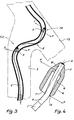
- Fig. 4 shows an enlarged sectional view of the tip of the stylus according to FIG. 3.
- FIG. 1 a first embodiment of a stylus according to the invention.
- the latter comprises an elastic wire 1 terminating at its posterior end by a button 2 intended to facilitate gripping by the surgeon.
- this wire can be slightly frustoconical.
- a blunt element or tip 3 is attached to this wire. It has a general ogive shape with a rounded end face 4, a frustoconical surface 5 which is connected to this face and to a cylindrical surface 6 which follows the latter. Overall, the tip 3 thus has an axial symmetry with respect to the longitudinal axis of the stylus.
- the assembly of the end-piece and the corresponding end of the wire is preferably carried out by soldering or by crimping this end into the body of the end-piece.
- the entire stylus can be made of stainless steel, for example.
- the largest diameter of the tip can be 0.60 mm for an internal diameter of 0.80 mm of the conductor (not shown) of an implantable electrode with which the stylus is associated .
- the length of the endpiece can be 1.20 mm, while the diameter of the wire in its cylindrical part can be 0.20 mm. Of course, all these dimensions are given for information only.
- the end piece 3 is solid, the wire 1 extending freely, only from the rear face 7 of this end piece.
- the end piece 3 comprises a blind axial cavity 8 of generally cylindrical shape and opening onto the rear face 7 of the end piece. It will be noted that the diameter of this cavity clearly exceeds that of the wire 1; for example when the latter has a diameter of 0.20 mm, the cavity may have a diameter of 0.35 mm.
- the anterior end of the wire that is to say its frustoconical part 9 passes through the cavity 8 and is threaded into an axial orifice 10 which extends the cavity 8 at the front.
- a weld 11 is provided at the end face 4, this weld being worked in such a way that this face is connected without discontinuities to the frustoconical surface 5.
- Another way to assemble the end piece 3 to the wire 1 consists in riveting the latter to the front face by making it slightly protrude from the orifice 10 before the riveting operation.
- the wire can be easily positioned in the axial direction relative to the end piece 3 and the wire can be cut to the desired length at the front end of the orifice 10, to then proceed to the assembly operation, by welding or riveting.
- the inclination of the frustoconical surface 5 relative to the axis of the stylus must be carefully chosen.
- the angle can vary between 15 and 50 ° approximately, but it has been found that an angle of 26 ° can ensure adaptation to the degrees of curvature. most frequent of the implanted electrode.
- connection 12 with a curved section between the side wall of the end piece 3 and its rear face 7 and this in order to facilitate the removal of the stylus from the electrode after implantation or control of the latter.
- Fig. 3 illustrates the operation of a stylus produced according to FIG. 2. It shows a blood vessel V through which passes an electrode E formed by a winding with contiguous turns of a wire C itself formed by several strands wound in a helix. It is supposed that a secondary blood vessel VS leads to the main vessel V and that after a few days of presence in the body, the electrode E has formed at this point a pronounced elbow with first a curve to the right (CD) then a curve to the left (CG) seen from the posterior end of the electrode (bottom in the Figure).
- the stylus according to the invention When the stylus according to the invention is not subjected to any constraint, it is perfectly straight, as shown in FIG. 1 and it resumes this shape each time a curvature constraint is applied to it. However, it remains flexible enough to be able to fit into all the curvatures imposed on it by the shape of the electrode during implantation or subsequent insertion.
- this tilting torque can be generated regardless of the direction of the curvature (that is to say in the plane of Fig. 3 or out of this plane).
Description
La présente invention est relative aux électrodes implantables dans le corps et elle concerne plus particulièrement les stylets qui sont associés à ces électrodes pour les rigidifier lors de leur implantation.The present invention relates to electrodes implantable in the body and it relates more particularly to the styli which are associated with these electrodes to stiffen them during their implantation.
A l'heure actuelle, les électrodes implantables sont largement répandues et utilisées en médecine pour établir des diagnostics, soigner des malades et surtout pour équiper les patients qui ont une affection cardiaque à laquelle on tente de remédier par l'implantation à demeure d'un stimulateur.At present, implantable electrodes are widely used and used in medicine to establish diagnoses, treat patients and especially to equip patients who have a heart condition which is being tried to remedy by permanent implantation of a stimulator.
Ces électrodes sont formées par un conducteur électrique creux extrêmement souple et gainé sur toute sa longueur d'un matériau isolant. Le conducteur lui-même est formé d'un enroulement en hélice de plusieurs torons de fil, eux-mêmes généralement formés d'hélices à leur tour. Un tel agencement permet d'assurer la souplesse de l'électrode requise pour qu'elle puisse s'adapter à chaque instant aux modifications de forme des vaisseaux sanguins, en particulier à proximité du coeur. Cependant, lors de l'implantation, pour pouvoir suivre tous les méandres des vaisseaux, il convient que l'électrode soit assez rigide et c'est précisément le stylet qui assure temporairement cette rigidité. Ainsi, ce stylet est formé par un fil en métal élastique introduit dans l'électrode et présentant à peu près la même longueur que celle-ci.These electrodes are formed by an extremely flexible hollow electrical conductor sheathed over its entire length with an insulating material. The conductor itself is formed of a helical winding of several strands of wire, themselves generally formed of helices in turn. Such an arrangement makes it possible to ensure the flexibility of the electrode required so that it can adapt at all times to changes in the shape of the blood vessels, in particular near the heart. However, during implantation, to be able to follow all the meanders of the vessels, the electrode should be fairly rigid and it is precisely the stylus which temporarily ensures this rigidity. Thus, this stylus is formed by an elastic metal wire introduced into the electrode and having approximately the same length as the latter.
Par conséquent, lorsque le chirurgien a implanté l'électrode munie de son stylet, il retire immédiatement celui-ci et procède ensuite à la connexion de l'électrode avec le stimulateur ou un autre appareil analogue.Therefore, when the surgeon has implanted the electrode with his stylus, he immediately removes it and then proceeds to connect the electrode with the stimulator or other similar device.
On sait, par ailleurs, que les électrodes, surtout celles destinées à la stimulation cardiaque, doivent s'accrocher aux tissus à exciter ce qui est réalisé en général par des configurations spéciales de la tête de l'électrode (relief particulier de la surface de la tête, barbillons inclinés sur l'axe etc.). Malgré cela, il arrive encore fréquem- ment que l'électrode se décroche, surtout au cours des premières semaines suivant l'implantation, car alors le tissu n'a pas encore crû suffisamment pour assurer le maintien de l'électrode. Les chirurgiens ont donc l'habitude de contrôler l'accrochage de l'électrode quelque temps après leur intervention. Cette opération peut être effectuée à l'aide d'un stylet analogue à celui qui est utilisé pour l'implantation.It is known, moreover, that the electrodes, especially those intended for cardiac stimulation, must cling to the tissues to be excited, which is generally achieved by special configurations of the head of the electrode (particular relief of the surface of the head, barbs inclined on the axis etc.). Despite this, it still frequently happens that the electrode detaches, especially during the first weeks after implantation, because then the tissue has not yet grown enough to maintain the electrode. Surgeons are therefore used to checking the attachment of the electrode some time after their intervention. This can be done using a stylus similar to the one used for implantation.
Une électrode implantée suit normalement étroitement le trajet défini par le vaisseau sanguin dans lequel elle est insérée. Cependant, parfois, sa forme peut devenir assez sinueuse après le retrait du stylet, surtout à l'endroit où le vaisseau comporte un embranchement. L'électrode peut alors décrire des courbes serrées simples voire doubles en forme de S, par exemple. Or, si le stylet comporte un simple embout émoussant tel qu'une bille (comme décrit par exemple dans le brevet GB-A-2 064 963) ou encore plus simplement une surface d'extrémité arrondie (comme décrit dans le brevet US-A-2 118 631), il ne se laisse que difficilement insérer dans l'électrode, car dans les courbes, l'embout s'accroche sur les spires jointives de l'électrode tendant à les écarter voire à passer à travers le conducteur et la gaine isolante qui l'entoure. Il y à alors un risque important que le stylet en passant à travers la gaine isolante de l'électrode perce le vaisseau sanguin. Dans ces conditions, les praticiens préfèrent abandonner cette méthode de contrôle à l'aide du stylet et avoir recours à l'examen aux rayons X pour vérifier la bonne implantation.An implanted electrode normally follows closely the path defined by the blood vessel in which it is inserted. However, sometimes its shape can become quite curvy after removing the stylus, especially where the vessel has a branch. The electrode can then describe tight single or even double S-shaped curves, for example. However, if the stylus comprises a simple blunt end such as a ball (as described for example in patent GB-A-2,064,963) or even more simply a rounded end surface (as described in patent US-A -2 118 631), it is only difficult to insert into the electrode, because in the curves, the endpiece is hooked on the contiguous turns of the electrode tending to spread them apart or even pass through the conductor and the insulating sheath which surrounds it. There is then a significant risk that the stylus passing through the insulating sheath of the electrode pierces the blood vessel. Under these conditions, practitioners prefer to abandon this method of control using the stylus and resort to X-ray examination to verify the correct implantation.
L'invention a pour but de fournir un stylet qui permette le contrôle de l'implantation sans aucun risque de percement ni du conducteur de l'électrode, ni du vaisseau sanguin.The object of the invention is to provide a stylus which allows implantation control without any risk of piercing either of the electrode conductor or of the blood vessel.
L'invention a donc pour objet un stylet pour la mise en place et le contrôle d'une électrode implantable du type comprenant un conducteur creux allongé formé d'un enroulement en hélice à spires jointives d'un fil, ledit stylet comprenant un fil élastique qui, lors de l'implantation de l'électrode, est maintenu dans celle-ci pour la rigidifier sur toute sa longueur et qui présente à son extrémité antérieure un embout émoussant à symétrie axiale fixée coaxialement à l'extrémité antérieure du fil, son diamètre étant légèrement inférieur au diamètre intérieur du conducteur de l'électrode, caractérisé en ce que l'embout émoussant présente une forme en ogive.The subject of the invention is therefore a stylet for positioning and controlling an implantable electrode of the type comprising an elongated hollow conductor formed by a helical winding with contiguous turns of a wire, said stylet comprising an elastic wire which, during the implantation of the electrode, is held therein to stiffen it over its entire length and which has at its front end a blunt endpiece with axial symmetry fixed coaxially to the front end of the wire, its diameter being slightly less than the inside diameter of the electrode conductor, characterized in that the blunt end piece has a pointed shape.
Grâce à cette forme particulière de l'élément émoussant, l'accrochage sur les spires du conducteur ne peut se produire, même si ce conducteur décrit une courbe serrée, car lorsqu'une poussée axiale dans le sens de l'insertion est appliquée sur le fil élastique, celui-ci par son flambage dû à la résistance apportée par l'élément émoussant, applique un léger couple de basculement sur celui-ci en écartant son extrémité antérieure des spires du conducteur. Ainsi, de proche en proche, l'élément émoussant passe devant les spires jointives dans les courbes du conducteur facilitant ainsi considérablement la progression du stylet.Thanks to this particular form of the blunting element, the hooking on the turns of the conductor cannot occur, even if this conductor describes a tight curve, because when an axial thrust in the direction of insertion is applied to the elastic thread, the latter by its buckling due to the resistance provided by the blunting element, applies a slight tilting torque on the latter by moving its front end away from the turns of the conductor. Thus, step by step, the blunting element passes in front of the contiguous turns in the curves of the conductor thus considerably facilitating the progression of the stylus.
Le couple de basculement peut être augmenté pour faciliter encore davantage cette progression si, suivant une autre caractéristique de l'invention, l'élément émoussant comporte une cavité cylindrique axiale borgne ouverte vers l'arrière et traversée par l'extrémité antérieure du fil, ce dernier étant fixé à l'embout dans la zone du fond de la cavité, celle-ci ayant un diamètre supérieur à celui du fil élastique.The tilting torque can be increased to further facilitate this progression if, according to another characteristic of the invention, the blunting element comprises a blind axial cylindrical cavity open towards the rear and crossed by the anterior end of the wire, this the latter being fixed to the endpiece in the region of the bottom of the cavity, the latter having a diameter greater than that of the elastic wire.
C'est en effet dans ces conditions que les forces qui créent le couple de basculement peuvent avoir des points d'application aussi éloignés que possible les uns des autres. De la sorte, des courbes encore plus serrées peuvent être franchies sans risque de percement ni de la gaine isolante de l'électrode, ni, à fortiori, de la paroi du vaisseau sanguin.It is indeed under these conditions that the forces which create the tilting torque can have points of application as distant as possible from each other. In this way, even tighter curves can be crossed without risk of piercing either of the insulating sheath of the electrode, or, a fortiori, of the wall of the blood vessel.
L'invention sera mieux comprise à l'aide de la description qui va suivre d'un exemple de réalisation.The invention will be better understood with the aid of the description which follows of an exemplary embodiment.
Aux dessins annexés, donnés uniquement à titre d'exemple:
- - la Fig. 1 est une vue à grande échelle et en coupe axiale de la partie antérieure d'un stylet suivant l'invention;
- - la Fig. 2 montre un autre mode de réalisation, actuellement préféré;
- - la Fig. 3 représente schématiquement comment l'embout du stylet parvient à favoriser la progression du stylet dans une électrode qui est déjà implantée et qui suit un trajet sinueux.
- - Fig. 1 is a large scale view in axial section of the front part of a stylus according to the invention;
- - Fig. 2 shows another embodiment, currently preferred;
- - Fig. 3 schematically shows how the tip of the stylus manages to promote the progression of the stylus in an electrode which is already implanted and which follows a winding path.
La Fig. 4 montre une vue en coupe à grande échelle de l'embout du stylet suivant la Fig. 3.Fig. 4 shows an enlarged sectional view of the tip of the stylus according to FIG. 3.
On a montré sur la Fig. 1, une première formé de réalisation d'un stylet suivant l'invention. Ce dernier comporte un fil élastique 1 se terminant à son extrémité postérieure par un bouton 2 destiné à faciliter la préhension par le chirurgien. Dans sa partie antérieure ce fil peut être légèrement tronconique.We have shown in FIG. 1, a first embodiment of a stylus according to the invention. The latter comprises an elastic wire 1 terminating at its posterior end by a button 2 intended to facilitate gripping by the surgeon. In its front part this wire can be slightly frustoconical.
Un élément émoussant ou embout 3 est fixé à ce fil. Il présente une forme générale en ogive avec une face d'extrémité 4 arrondie, une surface tronconique 5 qui se raccorde à cette face et à une surface cylindrique 6 qui fait suite à cette dernière. Dans l'ensemble, l'embout 3 présente ainsi une symétrie axiale par rapport à l'axe longitudinal du stylet.A blunt element or
L'assemblage de l'embout et de l'extrémité correspondante du fil est réalisé de préférence par brasage ou par sertissage de cette extrémité dans le corps de l'embout.The assembly of the end-piece and the corresponding end of the wire is preferably carried out by soldering or by crimping this end into the body of the end-piece.
L'ensemble du stylet peut être réalisé en acier inoxydable, par exemple.The entire stylus can be made of stainless steel, for example.
Par ailleurs et pour fixer les idées, le diamètre le plus grand de l'embout peut être de 0,60 mm pour un diamètre intérieur de 0,80 mm du conducteur (non représenté) d'une électrode implantable à laquelle le stylet est associé. La longueur de l'embout peut être de 1,20 mm, tandis que le diamètre du fil dans sa partie cylindrique peut être de 0,20 mm. Bien entendu, toutes ces dimensions ne sont données qu'à titre indicatif.Furthermore and to fix ideas, the largest diameter of the tip can be 0.60 mm for an internal diameter of 0.80 mm of the conductor (not shown) of an implantable electrode with which the stylus is associated . The length of the endpiece can be 1.20 mm, while the diameter of the wire in its cylindrical part can be 0.20 mm. Of course, all these dimensions are given for information only.
Dans la version représentée à la Fig. 1, l'embout 3 est massif, le fil 1 s'étendant librement, seulement à partir de la face postérieure 7 de cet embout.In the version shown in FIG. 1, the
Par contre, dans le mode de réalisation de la Fig. 2, qui est actuellement préféré, l'embout 3 comporte une cavité axiale borgne 8 de forme générale cylindrique et s'ouvrant sur la face postérieure 7 de l'embout. On remarquera que le diamètre de cette cavité dépasse nettement celui du fil 1; par exemple lorsque celui-ci a un diamètre de 0,20 mm, la cavité peut avoir un diamètre de 0,35 mm.On the other hand, in the embodiment of FIG. 2, which is currently preferred, the
L'extrémité antérieure du fil, c'est-à-dire sa partie tronconique 9 passe à travers la cavité 8 et est enfilée dans un orifice axial 10 qui prolonge la cavité 8 à l'avant. Afin d'assurer la fixation du fil dans cet orifice 10, il est prévu une soudure 11 à la face d'extrémité 4, cette soudure étant travaillée de telle façon que cette face se raccorde sans discontinuités à la surface tronconique 5. Une autre façon d'assembler l'embout 3 au fil 1 consiste à river ce dernier à la face avant en le faisant légèrement dépasser de l'orifice 10 avant l'opération de rivetage.The anterior end of the wire, that is to say its
On peut noter que grâce à la légère conicité de l'extrémité antérieure 8, on peut positionner facilement le fil dans le sens axial par rapport à l'embout 3 et couper le fil à la longueur souhaitée à l'extrémité avant de l'orifice 10, pour ensuite procéder à l'opération d'assemblage, par soudure ou rivetage.It can be noted that thanks to the slight conicity of the
Il s'est avéré que l'inclinaison de la surface tronconique 5 par rapport à l'axe du stylet doit être soigneusement choisie. Suivant le degré de courbure auquel on peut s'attendre lorsqu'une électrode est implantée, l'angle peut varier entre 15 et 50° environ, mais on a constaté qu'un angle de 26° pouvait assurer une adaptation aux degrés de courbure les plus fréquents de l'électrode implantée.It turned out that the inclination of the
Il est également avantageux de prévoir un raccord 12 à section courbe entre la paroi latérale de l'embout 3 et sa face postérieure 7 et ceci afin de faciliter le retrait du stylet de l'électrode après l'implantation ou le contrôle de cette dernière.It is also advantageous to provide a
La Fig. 3 illustre le fonctionnement d'un stylet réalisé selon la Fig. 2. Elle montre un vaisseau sanguin V dans lequel passe une électrode E formé d'un enroulement à spires jointives d'un fil C lui-même formé de plusieurs torons enroulés en hélice. On suppose qu'un vaisseau sanguin secondaire VS débouche sur le vaisseau principal V et qu'après quelques jours de présence dans le corps, l'électrode E a formé à cet endroit un coude prononcé avec d'abord une courbe à droite (CD) puis une courbe à gauche (CG) vu de l'extrémité postérieure de l'électrode (en bas sur la Figure).Fig. 3 illustrates the operation of a stylus produced according to FIG. 2. It shows a blood vessel V through which passes an electrode E formed by a winding with contiguous turns of a wire C itself formed by several strands wound in a helix. It is supposed that a secondary blood vessel VS leads to the main vessel V and that after a few days of presence in the body, the electrode E has formed at this point a pronounced elbow with first a curve to the right (CD) then a curve to the left (CG) seen from the posterior end of the electrode (bottom in the Figure).
Lorsque le stylet suivant l'invention n'est soumis à aucune contrainte, il est parfaitement rectiligne, comme représenté à la Fig. 1 et il reprend cette forme chaque fois qu'une contrainte de courbure lui est appliquée. Cependant, il demeure suffisamment souple pour pouvoir s'inscrire dans toutes les courbures qui lui sont imposées par la forme de l'électrode lors de l'implantation ou de l'insertion ultérieure.When the stylus according to the invention is not subjected to any constraint, it is perfectly straight, as shown in FIG. 1 and it resumes this shape each time a curvature constraint is applied to it. However, it remains flexible enough to be able to fit into all the curvatures imposed on it by the shape of the electrode during implantation or subsequent insertion.
Par conséquent, lorsque dans le cas de la Fig. 3, l'embout 3 aborde la courbure à droite, il vient se heurter très rapidement contre la paroi intérieure de l'électrode.Therefore, when in the case of FIG. 3, the
L'effet de blocage est d'autant plus important que cette paroi est formée par des spires contiguës entre lesquelles sont formées des dépressions. C'est ce qui empêchait toute progression des stylets conçus suivant la technique antérieure comportant un simple embout émoussant formé par une bille fine.The blocking effect is all the more important since this wall is formed by contiguous turns between which depressions are formed. This is what prevented any progression of styli designed according to the prior art comprising a simple blunt tip formed by a fine ball.
Cependant, grâce à la forme particulière de l'embout suivant l'invention, dès qu'une légère contrainte est exercée sur le fil dans le sens axial, contrainte qui est donc due à la force de blocage de l'embout et la force de poussée exercée sur le stylet par le chirurgien, le fil subit un très léger flambage qui a tendance à faire basculer l'embout par rapport à l'axe de la partie antérieure 9 du fil 1. De ce fait, l'embout viendra en contact avec la paroi de l'électrode, non pas par la face 4, mais par la face tronconique 5 qui, en raison de son inclinaison soigneusement choisie, assurera un contact glissant qui favorise la progression du stylet. Ce processus se produit chaque fois que l'embout est arrêté contre la paroi intérieure de l'électrode.However, thanks to the particular shape of the endpiece according to the invention, as soon as a slight stress is exerted on the wire in the axial direction, this stress is therefore due to the locking force of the endpiece and the force of thrust on the stylus by the surgeon, the wire undergoes a very slight buckling which tends to tilt the endpiece relative to the axis of the
Une analyse très simplifiée fait apparaître que l'embout 3 subit un couple de basculement, F - F, tendant à chaque fois de l'éloigner de la paroi, ou tout au moins d'y appliquer une génératrice de la partie tronconique 5 de l'embout 3.A very simplified analysis shows that the
En raison de la symétrie axiale de celui-ci ce couple de basculement peut être engendré quel que soit le sens de la courbure (c'est-à-dire dans le plan de la Fig. 3 ou hors de ce plan).Due to the axial symmetry thereof, this tilting torque can be generated regardless of the direction of the curvature (that is to say in the plane of Fig. 3 or out of this plane).
Le phénomène qui vient d'être décrit a lieu tant dans le cas de la Fig. 1 que dans celui des Fig. 2 et 4, dont la variante provoque une nette augmentation du couple de basculement du fait que la force d'éloignement est ramenée le plus proche possible vers l'extrémité avant de l'embout 3. Par ailleurs, si le flambage du fil 1 est suffisant, le contact de celui-ci avec la paroi de la cavité en 13 (Fig. 4) renforce encore davantage le phénomène recherché.The phenomenon which has just been described takes place both in the case of FIG. 1 as in that of FIGS. 2 and 4, the variant of which causes a marked increase in the tilting torque due to the fact that the force of separation is brought as close as possible towards the front end of the
Claims (6)
Applications Claiming Priority (2)
| Application Number | Priority Date | Filing Date | Title |
|---|---|---|---|
| FR8509986A FR2583985B1 (en) | 1985-06-27 | 1985-06-27 | STYLET FOR ELECTRODE IMPLANTABLE IN THE BODY |
| FR8509986 | 1985-06-27 |
Publications (2)
| Publication Number | Publication Date |
|---|---|
| EP0207438A1 EP0207438A1 (en) | 1987-01-07 |
| EP0207438B1 true EP0207438B1 (en) | 1989-08-23 |
Family
ID=9320821
Family Applications (1)
| Application Number | Title | Priority Date | Filing Date |
|---|---|---|---|
| EP86108681A Expired EP0207438B1 (en) | 1985-06-27 | 1986-06-25 | Stylet for an implantable electrode |
Country Status (7)
| Country | Link |
|---|---|
| US (1) | US4791939A (en) |
| EP (1) | EP0207438B1 (en) |
| DE (1) | DE3665127D1 (en) |
| DK (1) | DK166191C (en) |
| FR (1) | FR2583985B1 (en) |
| HK (1) | HK5393A (en) |
| SG (1) | SG77692G (en) |
Cited By (5)
| Publication number | Priority date | Publication date | Assignee | Title |
|---|---|---|---|---|
| US6197324B1 (en) | 1997-12-18 | 2001-03-06 | C. R. Bard, Inc. | System and methods for local delivery of an agent |
| US6248112B1 (en) | 1998-09-30 | 2001-06-19 | C. R. Bard, Inc. | Implant delivery system |
| US6251418B1 (en) | 1997-12-18 | 2001-06-26 | C.R. Bard, Inc. | Systems and methods for local delivery of an agent |
| US6689121B1 (en) | 1998-09-24 | 2004-02-10 | C. R. Bard, Inc. | Systems and methods for treating ischemia |
| US6692520B1 (en) | 1998-12-15 | 2004-02-17 | C. R. Bard, Inc. | Systems and methods for imbedded intramuscular implants |
Families Citing this family (39)
| Publication number | Priority date | Publication date | Assignee | Title |
|---|---|---|---|---|
| DE8803153U1 (en) * | 1988-03-09 | 1988-06-23 | B. Braun Melsungen Ag, 3508 Melsungen, De | |
| US5013310A (en) * | 1988-11-09 | 1991-05-07 | Cook Pacemaker Corporation | Method and apparatus for removing an implanted pacemaker lead |
| US5207683A (en) * | 1988-11-09 | 1993-05-04 | Cook Pacemaker Corporation | Apparatus for removing an elongated structure implanted in biological tissue |
| US6136005A (en) * | 1988-11-09 | 2000-10-24 | Cook Pacemaker Corporation | Apparatus for removing a coiled structure implanted in biological tissue, having expandable means including a laterally deflectable member |
| US5507751A (en) * | 1988-11-09 | 1996-04-16 | Cook Pacemaker Corporation | Locally flexible dilator sheath |
| US5697936A (en) * | 1988-11-10 | 1997-12-16 | Cook Pacemaker Corporation | Device for removing an elongated structure implanted in biological tissue |
| US5040543A (en) * | 1990-07-25 | 1991-08-20 | C. R. Bard, Inc. | Movable core guidewire |
| SE9202481D0 (en) * | 1992-08-28 | 1992-08-28 | Siemens Elema Ab | CONTROLLABLE ELECTRIC DEVICE |
| US5383922A (en) * | 1993-03-15 | 1995-01-24 | Medtronic, Inc. | RF lead fixation and implantable lead |
| US5876408A (en) * | 1997-06-12 | 1999-03-02 | Sulzer Intermedics, Inc. | Method for enhancing implantation of thin leads |
| KR100442408B1 (en) * | 1998-11-05 | 2004-11-06 | 제일모직주식회사 | Polythiophene Conductive Polymer Solution Composition with High Conductivity and High Transparency |
| KR100390578B1 (en) * | 1998-12-17 | 2003-12-18 | 제일모직주식회사 | High refractive index conductive polymer thin film transparent film coating liquid composition |
| US6383519B1 (en) * | 1999-01-26 | 2002-05-07 | Vita Special Purpose Corporation | Inorganic shaped bodies and methods for their production and use |
| SE9901032D0 (en) * | 1999-03-22 | 1999-03-22 | Pacesetter Ab | Medical electrode lead |
| US7499756B2 (en) * | 1999-04-05 | 2009-03-03 | Spectranetics | Lead locking device and method |
| US20040236396A1 (en) * | 1999-04-05 | 2004-11-25 | Coe Michael Sean | Lead locking device and method |
| US6167315A (en) * | 1999-04-05 | 2000-12-26 | Spectranetics Corporation | Lead locking device and method |
| US8428747B2 (en) * | 1999-04-05 | 2013-04-23 | The Spectranetics Corp. | Lead locking device and method |
| US6620170B1 (en) * | 1999-04-26 | 2003-09-16 | C. R. Bard, Inc. | Devices and methods for treating ischemia by creating a fibrin plug |
| US6855160B1 (en) | 1999-08-04 | 2005-02-15 | C. R. Bard, Inc. | Implant and agent delivery device |
| US6458162B1 (en) * | 1999-08-13 | 2002-10-01 | Vita Special Purpose Corporation | Composite shaped bodies and methods for their production and use |
| US7232421B1 (en) | 2000-05-12 | 2007-06-19 | C. R. Bard, Inc. | Agent delivery systems |
| EP1284782B1 (en) | 2000-05-17 | 2005-07-20 | Cook Vascular Incorporated | Lead removal apparatus |
| US6611710B2 (en) * | 2000-11-29 | 2003-08-26 | Pacesetter, Inc. | Double threaded stylet for extraction of leads with a threaded electrode |
| US6763270B1 (en) | 2001-08-07 | 2004-07-13 | Pacesetter, Inc. | Lead extraction mechanism for active fixation leads |
| US6944506B1 (en) * | 2002-06-25 | 2005-09-13 | Pacesetter, Inc. | Stylet feature for resisting perforation of an implantable lead |
| US7189263B2 (en) * | 2004-02-03 | 2007-03-13 | Vita Special Purpose Corporation | Biocompatible bone graft material |
| EP1722696A1 (en) * | 2004-02-27 | 2006-11-22 | Cook Vascular TM Incorporated | Device for removing an elongated structure implanted in biological tissue |
| US9220595B2 (en) | 2004-06-23 | 2015-12-29 | Orthovita, Inc. | Shapeable bone graft substitute and instruments for delivery thereof |
| US20070066987A1 (en) * | 2005-09-09 | 2007-03-22 | Scanlan Donald L Jr | Bone navigation probes |
| WO2007100474A2 (en) * | 2006-02-13 | 2007-09-07 | Cook Vascular Incorporated | Device and method for removing lumenless leads |
| CA2656050C (en) | 2006-06-29 | 2015-02-03 | Orthovita, Inc. | Kit for bone graft comprising collagen,calcium phosphate,and bioactive glass |
| US8469971B2 (en) * | 2008-08-12 | 2013-06-25 | Boston Scientific Neuromodulation Corporation | Stylet for guiding leads of implantable electric stimulation systems and methods of making and using |
| US8551525B2 (en) | 2010-12-23 | 2013-10-08 | Biostructures, Llc | Bone graft materials and methods |
| US9775978B2 (en) | 2014-07-25 | 2017-10-03 | Warsaw Orthopedic, Inc. | Drug delivery device and methods having a retaining member |
| US10080877B2 (en) | 2014-07-25 | 2018-09-25 | Warsaw Orthopedic, Inc. | Drug delivery device and methods having a drug cartridge |
| US10076650B2 (en) | 2015-11-23 | 2018-09-18 | Warsaw Orthopedic, Inc. | Enhanced stylet for drug depot injector |
| USD802755S1 (en) | 2016-06-23 | 2017-11-14 | Warsaw Orthopedic, Inc. | Drug pellet cartridge |
| US10434261B2 (en) | 2016-11-08 | 2019-10-08 | Warsaw Orthopedic, Inc. | Drug pellet delivery system and method |
Family Cites Families (12)
| Publication number | Priority date | Publication date | Assignee | Title |
|---|---|---|---|---|
| US1730993A (en) * | 1928-01-31 | 1929-10-08 | Thomas & Betts Corp | Electrical-wire fishline |
| US2118631A (en) * | 1935-04-03 | 1938-05-24 | Wappler Frederick Charles | Catheter stylet |
| US2816552A (en) * | 1954-06-29 | 1957-12-17 | Roy D Hoffman | Teat bistoury with improved cutter blade adjusting means |
| US2980398A (en) * | 1957-02-13 | 1961-04-18 | William E Raney | Fish tape leader |
| CH484538A (en) * | 1969-03-14 | 1970-01-15 | Abnox Ag | Pneumatically operated pulling device |
| GB1435797A (en) * | 1973-10-22 | 1976-05-12 | Surgimed As | Catheter guide for use in insertion of a catheter into the human body |
| US3999551A (en) * | 1975-01-07 | 1976-12-28 | Bio-Medical Research, Ltd. | Subcutaneous guide assembly |
| US4169479A (en) * | 1977-02-24 | 1979-10-02 | Rudolph Muto | Elongated, tapered flexible front guide for electrical catheters and method of use |
| US4498482A (en) * | 1979-12-13 | 1985-02-12 | Medtronic, Inc. | Transvenous pacing lead having improved stylet |
| JPS617684Y2 (en) * | 1979-12-13 | 1986-03-10 | ||
| US4564023A (en) * | 1983-03-28 | 1986-01-14 | Cordis Corporation | Retention skirt for pacing electrode assembly |
| US4676249A (en) * | 1986-05-19 | 1987-06-30 | Cordis Corporation | Multi-mode guidewire |
-
1985
- 1985-06-27 FR FR8509986A patent/FR2583985B1/en not_active Expired
-
1986
- 1986-06-24 DK DK297286A patent/DK166191C/en active
- 1986-06-25 DE DE8686108681T patent/DE3665127D1/en not_active Expired
- 1986-06-25 EP EP86108681A patent/EP0207438B1/en not_active Expired
- 1986-06-25 US US06/878,540 patent/US4791939A/en not_active Expired - Lifetime
-
1992
- 1992-07-30 SG SG776/92A patent/SG77692G/en unknown
-
1993
- 1993-01-21 HK HK53/93A patent/HK5393A/en not_active IP Right Cessation
Cited By (6)
| Publication number | Priority date | Publication date | Assignee | Title |
|---|---|---|---|---|
| US6197324B1 (en) | 1997-12-18 | 2001-03-06 | C. R. Bard, Inc. | System and methods for local delivery of an agent |
| US6251418B1 (en) | 1997-12-18 | 2001-06-26 | C.R. Bard, Inc. | Systems and methods for local delivery of an agent |
| US6689121B1 (en) | 1998-09-24 | 2004-02-10 | C. R. Bard, Inc. | Systems and methods for treating ischemia |
| US6248112B1 (en) | 1998-09-30 | 2001-06-19 | C. R. Bard, Inc. | Implant delivery system |
| US6447522B2 (en) | 1998-09-30 | 2002-09-10 | C. R. Bard, Inc. | Implant delivery system |
| US6692520B1 (en) | 1998-12-15 | 2004-02-17 | C. R. Bard, Inc. | Systems and methods for imbedded intramuscular implants |
Also Published As
| Publication number | Publication date |
|---|---|
| HK5393A (en) | 1993-01-29 |
| DE3665127D1 (en) | 1989-09-28 |
| DK297286D0 (en) | 1986-06-24 |
| SG77692G (en) | 1992-10-02 |
| DK166191C (en) | 1993-08-16 |
| DK166191B (en) | 1993-03-22 |
| FR2583985A1 (en) | 1987-01-02 |
| EP0207438A1 (en) | 1987-01-07 |
| DK297286A (en) | 1986-12-28 |
| US4791939A (en) | 1988-12-20 |
| FR2583985B1 (en) | 1988-08-05 |
Similar Documents
| Publication | Publication Date | Title |
|---|---|---|
| EP0207438B1 (en) | Stylet for an implantable electrode | |
| EP2929910B1 (en) | Intracardiac capsule and accessory for explanting same | |
| EP0605351B1 (en) | Instrument for the removal of a length of vein | |
| EP0575478B1 (en) | Improved pulmonary embolism prevention filter and associated positioning and fitting kit | |
| EP2959940B1 (en) | Implantable capsule with attachment by screwing, in particular an autonomous cardiac stimulation capsule | |
| EP0616793B1 (en) | Medical instrument for removing deposits from the interior walls of arteries or veins | |
| EP0993840B1 (en) | Lead implantable in the coronary veins for stimulating a left cavity of the heart | |
| EP0384819B1 (en) | Surgical suture, especially for sternotomy closure | |
| CH690088A5 (en) | steerable flexible tubular guide, in particular for a medical surgical device. | |
| EP2078512B1 (en) | System for blocking an aneurysm or similar in a blood vessel | |
| WO1996029029A1 (en) | Surgical anchoring piece for ligaments | |
| FR2915087A1 (en) | IMPLANT FOR TREATING A CARDIAC VALVE, IN PARTICULAR A MITRAL VALVE, MATERIAL INCULING THIS IMPLANT AND MATERIAL FOR PLACING THE IMPLANT. | |
| FR2910269A1 (en) | Heart valve e.g. heart mitral valve, processing equipment, has implant deployed from catheter while being moved and driven by rotation, where rotation allows implant to penetrate into tissue of ring while implant guides along ring | |
| FR2775891A1 (en) | Partial posterior intervertebral disc prosthesis | |
| WO2008043917A2 (en) | Multiple-needle surgical wire guide for a hollow organ and corresponding system | |
| FR2710833A1 (en) | Device for implanting a medical prosthesis in a conduit of a human or animal body and method of centering such a device. | |
| FR2823436A1 (en) | SURGICAL INSTRUMENT AND COMBINATION OF SUCH INSTRUMENT AND A WIRE GUIDANCE | |
| EP0238419A2 (en) | Hollow puncturing needle and its method of manufacture | |
| FR2734145A1 (en) | MEDICAL INSTRUMENT COMPRISING A DISTAL TERMINAL ELEMENT THAT CAN BE ELBOW | |
| EP0091895A1 (en) | Device for the suprapubic drainage of the bladder introduced through the urethra | |
| FR2941859A1 (en) | OSTEOSYNTHESIS SCREW. | |
| FR2696092A1 (en) | Kit for medical use composed of a filter and its device for placement in the vessel. | |
| FR2727617A1 (en) | Vein stripping instrument for ablation with invagination | |
| FR2724566A1 (en) | Motorised cardiac probe with electrode and retractable helix | |
| FR3087344A1 (en) | COUPLING SYSTEM BETWEEN AN AUTONOMOUS HEART CAPSULE AND ITS IMPLANTATION TOOL |
Legal Events
| Date | Code | Title | Description |
|---|---|---|---|
| PUAI | Public reference made under article 153(3) epc to a published international application that has entered the european phase |
Free format text: ORIGINAL CODE: 0009012 |
|
| AK | Designated contracting states |
Kind code of ref document: A1 Designated state(s): CH DE GB LI NL SE |
|
| 17P | Request for examination filed |
Effective date: 19870311 |
|
| 17Q | First examination report despatched |
Effective date: 19881206 |
|
| GRAA | (expected) grant |
Free format text: ORIGINAL CODE: 0009210 |
|
| AK | Designated contracting states |
Kind code of ref document: B1 Designated state(s): CH DE GB LI NL SE |
|
| REF | Corresponds to: |
Ref document number: 3665127 Country of ref document: DE Date of ref document: 19890928 |
|
| GBT | Gb: translation of ep patent filed (gb section 77(6)(a)/1977) | ||
| PLBE | No opposition filed within time limit |
Free format text: ORIGINAL CODE: 0009261 |
|
| STAA | Information on the status of an ep patent application or granted ep patent |
Free format text: STATUS: NO OPPOSITION FILED WITHIN TIME LIMIT |
|
| 26N | No opposition filed | ||
| EAL | Se: european patent in force in sweden |
Ref document number: 86108681.7 |
|
| PGFP | Annual fee paid to national office [announced via postgrant information from national office to epo] |
Ref country code: SE Payment date: 20000525 Year of fee payment: 15 |
|
| PGFP | Annual fee paid to national office [announced via postgrant information from national office to epo] |
Ref country code: CH Payment date: 20000529 Year of fee payment: 15 |
|
| PGFP | Annual fee paid to national office [announced via postgrant information from national office to epo] |
Ref country code: NL Payment date: 20000530 Year of fee payment: 15 Ref country code: GB Payment date: 20000530 Year of fee payment: 15 |
|
| PGFP | Annual fee paid to national office [announced via postgrant information from national office to epo] |
Ref country code: DE Payment date: 20000606 Year of fee payment: 15 |
|
| PG25 | Lapsed in a contracting state [announced via postgrant information from national office to epo] |
Ref country code: GB Free format text: LAPSE BECAUSE OF NON-PAYMENT OF DUE FEES Effective date: 20010625 |
|
| PG25 | Lapsed in a contracting state [announced via postgrant information from national office to epo] |
Ref country code: SE Free format text: LAPSE BECAUSE OF NON-PAYMENT OF DUE FEES Effective date: 20010626 |
|
| PG25 | Lapsed in a contracting state [announced via postgrant information from national office to epo] |
Ref country code: LI Free format text: LAPSE BECAUSE OF NON-PAYMENT OF DUE FEES Effective date: 20010630 Ref country code: CH Free format text: LAPSE BECAUSE OF NON-PAYMENT OF DUE FEES Effective date: 20010630 |
|
| PG25 | Lapsed in a contracting state [announced via postgrant information from national office to epo] |
Ref country code: NL Free format text: LAPSE BECAUSE OF NON-PAYMENT OF DUE FEES Effective date: 20020101 |
|
| EUG | Se: european patent has lapsed |
Ref document number: 86108681.7 |
|
| GBPC | Gb: european patent ceased through non-payment of renewal fee |
Effective date: 20010625 |
|
| REG | Reference to a national code |
Ref country code: CH Ref legal event code: PL |
|
| NLV4 | Nl: lapsed or anulled due to non-payment of the annual fee |
Effective date: 20020101 |
|
| PG25 | Lapsed in a contracting state [announced via postgrant information from national office to epo] |
Ref country code: DE Free format text: LAPSE BECAUSE OF NON-PAYMENT OF DUE FEES Effective date: 20020403 |