EP0200646A2 - Pliable frame and portable objects provided with such a frame - Google Patents
Pliable frame and portable objects provided with such a frame Download PDFInfo
- Publication number
- EP0200646A2 EP0200646A2 EP86400912A EP86400912A EP0200646A2 EP 0200646 A2 EP0200646 A2 EP 0200646A2 EP 86400912 A EP86400912 A EP 86400912A EP 86400912 A EP86400912 A EP 86400912A EP 0200646 A2 EP0200646 A2 EP 0200646A2
- Authority
- EP
- European Patent Office
- Prior art keywords
- folding
- rods
- axis
- central joint
- frame
- Prior art date
- Legal status (The legal status is an assumption and is not a legal conclusion. Google has not performed a legal analysis and makes no representation as to the accuracy of the status listed.)
- Withdrawn
Links
Images


Classifications
-
- A—HUMAN NECESSITIES
- A47—FURNITURE; DOMESTIC ARTICLES OR APPLIANCES; COFFEE MILLS; SPICE MILLS; SUCTION CLEANERS IN GENERAL
- A47C—CHAIRS; SOFAS; BEDS
- A47C19/00—Bedsteads
- A47C19/12—Folding bedsteads
- A47C19/126—Folding bedsteads foldable side to side and head to foot, e.g. umbrella type
-
- A—HUMAN NECESSITIES
- A61—MEDICAL OR VETERINARY SCIENCE; HYGIENE
- A61G—TRANSPORT, PERSONAL CONVEYANCES, OR ACCOMMODATION SPECIALLY ADAPTED FOR PATIENTS OR DISABLED PERSONS; OPERATING TABLES OR CHAIRS; CHAIRS FOR DENTISTRY; FUNERAL DEVICES
- A61G1/00—Stretchers
- A61G1/013—Stretchers foldable or collapsible
-
- A—HUMAN NECESSITIES
- A61—MEDICAL OR VETERINARY SCIENCE; HYGIENE
- A61G—TRANSPORT, PERSONAL CONVEYANCES, OR ACCOMMODATION SPECIALLY ADAPTED FOR PATIENTS OR DISABLED PERSONS; OPERATING TABLES OR CHAIRS; CHAIRS FOR DENTISTRY; FUNERAL DEVICES
- A61G1/00—Stretchers
- A61G1/04—Parts, details or accessories, e.g. head-, foot-, or like rests specially adapted for stretchers
- A61G1/052—Struts, spars or legs
-
- E—FIXED CONSTRUCTIONS
- E01—CONSTRUCTION OF ROADS, RAILWAYS, OR BRIDGES
- E01D—CONSTRUCTION OF BRIDGES, ELEVATED ROADWAYS OR VIADUCTS; ASSEMBLY OF BRIDGES
- E01D15/00—Movable or portable bridges; Floating bridges
- E01D15/12—Portable or sectional bridges
- E01D15/124—Folding or telescopic bridges; Bridges built up from folding or telescopic sections
-
- Y—GENERAL TAGGING OF NEW TECHNOLOGICAL DEVELOPMENTS; GENERAL TAGGING OF CROSS-SECTIONAL TECHNOLOGIES SPANNING OVER SEVERAL SECTIONS OF THE IPC; TECHNICAL SUBJECTS COVERED BY FORMER USPC CROSS-REFERENCE ART COLLECTIONS [XRACs] AND DIGESTS
- Y10—TECHNICAL SUBJECTS COVERED BY FORMER USPC
- Y10T—TECHNICAL SUBJECTS COVERED BY FORMER US CLASSIFICATION
- Y10T403/00—Joints and connections
- Y10T403/32—Articulated members
- Y10T403/32008—Plural distinct articulation axes
- Y10T403/32024—Single adjustment for plural axes
-
- Y—GENERAL TAGGING OF NEW TECHNOLOGICAL DEVELOPMENTS; GENERAL TAGGING OF CROSS-SECTIONAL TECHNOLOGIES SPANNING OVER SEVERAL SECTIONS OF THE IPC; TECHNICAL SUBJECTS COVERED BY FORMER USPC CROSS-REFERENCE ART COLLECTIONS [XRACs] AND DIGESTS
- Y10—TECHNICAL SUBJECTS COVERED BY FORMER USPC
- Y10T—TECHNICAL SUBJECTS COVERED BY FORMER US CLASSIFICATION
- Y10T403/00—Joints and connections
- Y10T403/32—Articulated members
- Y10T403/32254—Lockable at fixed position
- Y10T403/32262—At selected angle
- Y10T403/32319—At selected angle including pivot stud
- Y10T403/32327—At selected angle including pivot stud including radially spaced detent or latch component
- Y10T403/32336—Engaging notch or recess in outer periphery of component
Definitions
- the present invention relates to portable and folding objects such as a portable bridge, portable bed, or portable stretcher.
- portable objects which are the subject of the present invention are of the type which include folding connecting elements such as spacers and folding frames, extending between two parallel sets of load-bearing rods and these connecting elements entail limitations as regards the way to fold such an object.
- a folding stretcher is requested by people who walk on foot in places where there is no access to normal ambulance services, i.e. for exploratory expeditions in remote areas, for example mountaineering expeditions, hikers; combat infantry etc. In all these situations, there is usually a rescuer present who must carry the folding stretcher in addition to his personal equipment.
- the folding stretcher should not only be made of a material as light as possible but must also be able to fold in a volume-as low as possible, so as not to interfere with the freedom of movement of the wearer.
- the fabric and the folding support and bracing means impose limitations and constraints on the way of folding a stretcher and, consequently, known folding stretchers generally fold only twice, the first time by erasing the bracing and support elements so as to bring the two sets of support rods together and a second time by folding the two sets of rods in half, in order to reduce their size by half.
- a stretcher folded in this way to a length of 1.05 meters and it is obvious that a stretcher folded of this dimension hinders the movements of the wearer. It is therefore an object of the present invention to provide a folding stretcher which can be folded into a compact state of reduced size.
- the object of the present invention is to provide portable folding objects which can be folded into a compact folded form which is easy to carry and transport.
- the invention relates to a folding frame comprising first and second sets of supporting rods connected to each other by folding connecting means, each of the first and second sets of rods comprising a central joint, a pair of internal rods each articulated on an edge of the central joint so as to allow the internal rods to be bent towards one another around a folding axis which extends in space in a direction normal to the longitudinal axis of the 'set of supporting rods, a pair of end rods each connected to the associated internal rod by a joint (peripheral joint) so as to be able to bend around a folding axis extending in space in one direction which makes an angle with the folding axis of the central joint; the folding axis of the peripheral seal of the first set of load-bearing rods extending in space essentially normally to the fold axis of the central seal while the fold axis of the second set of load-bearing rods extends into the space in a direction which makes an angle other than 90 ° with the folding axis
- the invention also relates to a portable folding object provided with a folding frame as described.
- a typical application of the invention is that of a portable stretcher comprising a folded frame as described and a canvas held by said first and second sets of load-bearing rods.
- Another application of the invention is that of a portable bed provided with a folding frame as described, and yet another application of the invention being that of a portable bridge provided with a folding frame as described.
- the frames according to the invention are made of light metal, such as aluminum for example.
- the frame 'stretcher shown comprises a first rod set carrier 2 and a second set of carrier rods 3 connected by a pair of folding arquées4 spacers, each comprising a pair of bars 5 and a connecting part 6, each of the bars 5 being articulated by one end on a connecting piece 6 and by the other end on the set of associated carrying rods.
- the framework 1 On its rear side, the framework 1 comprises four feet 7, two integral with the set of rods 2 and two integral with the assembly of rods 3.
- the first set of rods 2 comprises a central joint 8 on which two internal rods 9 are articulated so as to allow each rod 9 to tilt 90 ° around an axis which extends in space in a normal direction to the longitudinal axis of the joint 8, so that it can come to occupy the positions represented in FIGS. 3 and 4.
- the first set of rods further comprises a pair of end rods 10 each connected with the associated rod 9 by a peripheral seal 11, the connection between the seals 11 and each of the rods 9 and 10 being produced so as to allow the assembly 10, 11 to bend around a folding axis which extends in space according to a direction normal to that of the folding axis of the central joint 8, as shown in FIGS. 4 to 6, in order to reach the double folded position shown in FIG. 7.
- the peripheral seals 11 are prevented from folding back by the canvas and the weight of the person carried.
- a second set of supporting rods 3 comprises a central joint 13, a pair of internal rods 14 articulated on the central joint 13 in the same way as the rods 9 are articulated on the central joint 8, and a pair of end rods 15, each of which is articulated to the associated rod 14 by a peripheral seal 16 so as to allow the assembly 15, 16 to bend around a folding axis which extends in space in a direction which makes with the folding axis of the joint 13 at an angle other than 90 °. Consequently, each end rod 15 can tilt in a plane which intersects the plane of the unfolded framework. For this reason, the seals 16 are provided with a locking mechanism to prevent their collapse, as will be described below in more detail.
- end rods 10 and 15 carry handles 17.
- each of the assemblies 9, 10, 11 and 14, 15, 16 is tilted 90 ° around the pivots by which the internal rods 9 and 14 are articulated on the central joints 8.
- the beginning of this phase folding is shown in broken lines in Figure 3 and the end of this phase is shown in solid lines in Figure 4.
- the frame is in the form U-shaped, elements 5, 6, spacers 4 and feet 7 being positioned inside the U as shown.
- the framework 1 is associated with a fabric which, in the unfolded state of FIG. 1, is located above the arched spacers 4 and this requires that the end rods 10 and 15 must all be folded on the same side of the fabric.
- the canvas has not been shown in the drawings for clarity of the representation.
- FIGS. 8 and 9 we see, on a larger scale, a seal 16 provided with a locking means for prevent unwanted bending of the bars 15 and 14 of the second set of support rods 3.
- the seal 16 comprises a curved elastic locking device consisting of two annular members 19 held by a connecting piece 20.
- Two plates 21 are mounted on the upper face of the seal 16 and each has a re-entrant edge retaining the extreme portions of the associated annular member 19. Near one of these ends, each plate 21 is made integral with the joint using a rivet 24.
- Each of the plates 21 is pierced with a hole 22 which cooperates with a boss 23 integral with the associated rod 14 or 15.
Abstract
@ L'ossature pliante (1) de l'invention comprend des premier et second ensembles de tiges porteuses (2, 3) qui sont reliés entre eux par des entretoises arquées pliantes (4). Chacun de ces ensembles (2, 3) comprend un joint central (8, 13) et une paire de tiges intérieures (9, 14) articulées chacune sur un bord du joint central pour permettre de plier ces tiges intérieures pour les rapprocher l'une de l'autre autour d'un axe transversal. Chaque ensemble (2, 3) comprend en outre une paire de tiges d'extrémité (10, 15) reliées chacune à la tige intérieure associée par un joint périphérique (11, 16). Les tiges d'extrémité (19) du premier ensemble (2) peuvent se plier autour d'un axe normal à l'axe de pliage du joint central alors que les tiges d'extrémité (15) du second ensemble (3) peuvent se plier autour d'un axe faisant avec l'axe de pliage du joint central un angle autre que 90'.
Description
La présente invention concerne les objets portatifs et pliants tel qu'un pont portatif, lit portatif, ou brancard portatif. Les objets portatifs faisant l'objet de la présente invention sont du type de ceux qui comprennent des éléments de liaison pliants telle que entretoises et armaturespliantes, s'étendant entre deux ensembles parallèles de tiges porteuses et ces éléments de liaison entraînent des limitations quant à la manière de plier un tel objet.The present invention relates to portable and folding objects such as a portable bridge, portable bed, or portable stretcher. The portable objects which are the subject of the present invention are of the type which include folding connecting elements such as spacers and folding frames, extending between two parallel sets of load-bearing rods and these connecting elements entail limitations as regards the way to fold such an object.
On va décrire l'invention ci-après notamment dans son application à un brancard pliant, mais cela ne constitue d'aucune façon une limitation de l'invention.The invention will be described below in particular in its application to a folding stretcher, but this does not in any way constitute a limitation of the invention.
De manière typique, un brancard pliant est réclamé par les personnes qui se déplacent à pied dans des endroits ou il n'y a aucun accès à des services d'ambulance normaux, c'est à dire pour les expéditions d'exploration'dans des régions éloignées, par exemple des expéditions d'alpinisme, randonneurs; infantrie de combat etc. Dans toutes ces situations, il y a présent d'habitude un secouriste qui doit porter le brancard pliant en plus de son équipement personnel.Typically, a folding stretcher is requested by people who walk on foot in places where there is no access to normal ambulance services, i.e. for exploratory expeditions in remote areas, for example mountaineering expeditions, hikers; combat infantry etc. In all these situations, there is usually a rescuer present who must carry the folding stretcher in addition to his personal equipment.
En conçoit aisément que dans de telles situations, il est d'une importance capitale que le brancard pliant, doive non seulement être réalisé en un matériau aussi léger que possible mais doive en outre pouvoir se plier dans un volume-aussi faible que possible, de façon à ne pas gêner la liberté de mouvement du porteur. Toutefois, la toile et les moyens de support et d'entretoisement pliants imposent des limitations et des contraintes à la façon de plier un brancard et, par conséquent, les brancards pliants connus ne se plient en règle générale que deux fois,'une première fois par effacement des éléments d'entretoisement et de support de façon à rapprocher les deux ensembles de tiges porteuses l'un de l'autre et une seconde fois par pliage des deux ensembles de tiges en deux, afin de réduire leur dimension de moitié. En admettant qu'un brancard présente en général une longueur de 2, 10 mètres, un brancard plié de cette manière à une longueur de 1, 05 mètres et il est évident qu'un brancard plié de cette dimension gêne les mouvements du porteur. Il est par conséquent un but de la présente invention de réaliser un brancard pliant pouvant être plié selon un état compact de dimension réduite.It is easy to see that in such situations it is of paramount importance that the folding stretcher should not only be made of a material as light as possible but must also be able to fold in a volume-as low as possible, so as not to interfere with the freedom of movement of the wearer. However, the fabric and the folding support and bracing means impose limitations and constraints on the way of folding a stretcher and, consequently, known folding stretchers generally fold only twice, the first time by erasing the bracing and support elements so as to bring the two sets of support rods together and a second time by folding the two sets of rods in half, in order to reduce their size by half. Assuming that a stretcher generally has a length of 2, 10 meters, a stretcher folded in this way to a length of 1.05 meters and it is obvious that a stretcher folded of this dimension hinders the movements of the wearer. It is therefore an object of the present invention to provide a folding stretcher which can be folded into a compact state of reduced size.
De manière générale, le but de la présente invention est de réaliser des objets pliants portatifs pouvant être pliés selon une forme pliée compacte facile à porter et à transporter.In general, the object of the present invention is to provide portable folding objects which can be folded into a compact folded form which is easy to carry and transport.
Pour ce faire, l'invention a pour objet une ossature pliante comprenant des premier et second ensembles de tiges porteuses reliées entre eux par des moyens de liaison pliantes, chacun des premier et second ensembles de tiges comprenant un joint central, une paire de tiges intérieures articulées chacune sur un bord du joint central de façon à permettre de plier les tiges intérieures l'une vers l'autre autour d'un axe de pliage qui s'étend dans l'espace selon une direction normale à l'axe longitudinale de l'ensemble de tiges porteuses, une paire de tiges d'extrémité reliées chacune à la tige intérieure associée par un joint (jôint périphérique) de façon à pouvoir se plier autour d'un axe de pliage s'étendant dans l'espace dans une direction qui fait un angle avec l'axe de pliage du joint central; l'axe de pliage du joint périphérique du premier ensemble de tiges porteuses s'étendant dans l'espace essentiellement normalement à l'axe de pliage du joint central alors que l'axe de pliage du second ensemble de tiges porteuses s'étend dans l'espace selon une direction qui fait avec l'axe de pliage du joint central un angle autre que 90°, de telle façon que, à l'état plié, les tiges d'extrémité du second ensemble viennent prendre appui entre les tiges d'extrémité du premier ensemble.To do this, the invention relates to a folding frame comprising first and second sets of supporting rods connected to each other by folding connecting means, each of the first and second sets of rods comprising a central joint, a pair of internal rods each articulated on an edge of the central joint so as to allow the internal rods to be bent towards one another around a folding axis which extends in space in a direction normal to the longitudinal axis of the 'set of supporting rods, a pair of end rods each connected to the associated internal rod by a joint (peripheral joint) so as to be able to bend around a folding axis extending in space in one direction which makes an angle with the folding axis of the central joint; the folding axis of the peripheral seal of the first set of load-bearing rods extending in space essentially normally to the fold axis of the central seal while the fold axis of the second set of load-bearing rods extends into the space in a direction which makes an angle other than 90 ° with the folding axis of the central joint, so that, in the folded state, the end rods of the second set come to bear between the rods end of the first set.
L'invention a également pour objet un objet pliant portatif doté d'une ossature pliante telle que décrite.The invention also relates to a portable folding object provided with a folding frame as described.
Une application typique de l'invention est celle d'un brancard portatif comprenant une ossature pliée telle que décrite et une toile maintenue par lesdits premier et second ensembles de tiges porteuses.A typical application of the invention is that of a portable stretcher comprising a folded frame as described and a canvas held by said first and second sets of load-bearing rods.
Une autre application de l'invention est celle d'un lit portatif doté d'une ossature pliante telle que décrite, et une autre application encore de l'invention étant celle d'un pont portatif doté d'une ossature pliante telle que décrite.Another application of the invention is that of a portable bed provided with a folding frame as described, and yet another application of the invention being that of a portable bridge provided with a folding frame as described.
De préférence, les ossatures conformes' à l'invention sont réalisées en métal léger, tel que de l'aluminium par example.Preferably, the frames according to the invention are made of light metal, such as aluminum for example.
L'invention est illustrée, à titre d'exemple uniquement, par les dessins annexés dans lesquels:
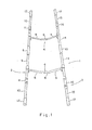
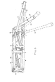
- la figure 1 est une vue de dessus en perspective d'une ossature de brancard conforme à l'invention, à l'état déplié;
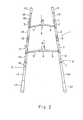
- la figure 2 est une vue en perspective depuis l'extrémité arrière de l'ossature de brancard représentée sur la figure 1;
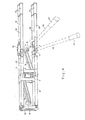
- la figure 3 est une vue latérale en perspective de l'ossature de la figure 1, mais à plus grande échelle, et la .représentant lors de l'étape initiale de pliage;
- les figures 4, 5 et 6 sont des vues en perspective représentant l'ossature lors de diverses étapes de pliage;
- la figure 7 est une vue en perspective représen- < tant le brancard à l'état entièrement plié; et
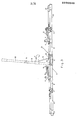
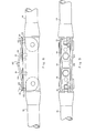
- les figures 8 et 9 sont respectivement des vues en élévation et en plan d'un des joints périphériques de 1'ossature, à plus grande échelle, représentant un mécanisme de blocages de ceux-ci.
- Figure 1 is a top perspective view of a stretcher frame according to the invention, in the unfolded state;
- Figure 2 is a perspective view from the rear end of the stretcher frame shown in Figure 1;
- Figure 3 is a perspective side view of the frame of Figure 1, but on a larger scale, and .representing during the initial folding step;
- Figures 4, 5 and 6 are perspective views representing the frame during various folding steps;
- Figure 7 is a perspective view showing the stretcher in the fully folded state; and
- FIGS. 8 and 9 are respectively elevation and plan views of one of the peripheral joints of the frame, on a larger scale, showing a blocking mechanism thereof.
L'ossature'de brancard représentée comprend un premier ensemble de tiges porteuses 2 et un second ensemble de tiges porteuses 3 reliés par une paire d'entretoises pliantes arquées4, comprenant chacune une paire de barres 5 et une pièce de liaison 6, chacune des barres 5 étant articulée par une extrémité sur une pièce de liaison 6 et par l'autre extrémité sur l'ensemble de tiges porteuses associé. Sur son côté arrière, l'ossature 1 comprend quatre pieds 7, deux solidaires-de l'ensemble de tiges 2 et deux solidaires de l'ensemble de tiges 3.The frame 'stretcher shown comprises a first rod set
Le premier ensemble de tiges 2 comprend un joint central 8 sur lequel s'articulent deux tiges intérieures 9 de façon à permettre à chaque tige 9 de basculer de 90° autour d'un axe qui s'étend dans l'espace dans une direction normale à l'axe longitudinal du joint 8, pour qu'elle puisse venir occuper les positions représentées sur les figures 3 et 4. Le premier ensemble de tiges comprend en outre une paire de tiges d'extrémité 10 reliéeschacune avec la tige associée 9 par un joint périphérique 11, la liaison entre les joints 11 et chacune des tiges 9 et 10 étant réalisée de façon à permettre à l'ensemble 10, 11 de se plier autour d'un axe de pliage qui s'étend dans l'espace selon une direction normale à celle de l'axe de pliage du joint central 8, de la manière représentée sur les figures 4 à 6, afin d'atteindre la position doublement pliée représentée sur la figure 7. A l'état entièrement déplié operationel du brancard, les joints périphériques 11 sont empêchés de se replier par la toile et le poids de la personne portée.The first set of
Un second ensemble de tiges porteuses 3 comprend un joint central 13, une paire de tiges intérieures 14 articuléessur le joint central 13 de la même manière que les tiges 9 sont articulées sur le joint central 8, et une paire de tiges d'extrémité 15, dont chacune est articulée à la tige associée 14 par un joint périphérique 16 de façon à permettre à l'ensemble 15, 16 de se plier autour d'un axe de pliage qui s'étend dans l'espace selon une direction qui fait avec l'axe de pliage du joint 13 un angle autre que 90°. Par conséquent, chaque tige d'extrémité 15 peut basculer dans un plan qui coupe le plan de l'ossature dépliée. Pour cette raison, les joints 16 sont dotés d'un mécanisme de blocage pour éviter leur affaissement, comme on va le décrire ci-après avec plus de détail.A second set of supporting
A leurs extrémités, les tiges d'extrémité 10 et 15 portent des poignées 17.At their ends, the
On va décrire maintenant le pliage de l'ossature 1.We will now describe the folding of frame 1.
Partant de l'état déplié représenté sur les figures 1 et 2, on fait plier les entretoises pliantes 4 en exerçant une pression sur les pièces de liaison 6 de façon que chaque barre 5 bascule comme l'indiquent les flèches sur la figure 2 et l'ossature atteint l'état représenté sur la figure 3, sur laquelle on voit les deux ensembles de tiges porteuses 2 et 3 disposés l'un à côté de l'autre. A partir de cet état, on fait basculer chacun des ensembles 9, 10, 11 et 14, 15, 16 de 90° autour des pivots par lesquels les tiges intérieures 9 et 14 sont articulées sur les joints centrals 8. Le début de cette phase de pliage est représenté-en traits interrompus sur la figure 3 et la fin de cette phase est représentée en traits continus sur la figure 4. Comme on le voit sur la figure 4, à la fin de cette phase l'ossature se présente sous forme de structure en U, les éléments 5, 6, les entretoises 4 et les pieds 7 étant positionnés à l'intérieur de l'U de la manière représentée.Starting from the unfolded state represented in FIGS. 1 and 2, the
Il est à noter que, dans la pratique, l'ossature 1 est associée à une toile qui, à l'état déplié de la figure 1, est située au-dessus des entretoises arquées 4 et cela impose que les tiges d'extrémité 10 et 15 doivent être toutes pliées sur la même face de la toile. La toile n'a pas été représentée sur les dessins pour plus de clarté de la représentation.It should be noted that, in practice, the framework 1 is associated with a fabric which, in the unfolded state of FIG. 1, is located above the
Comme il ressort clairement des figures 3 et 4, les orientations dans l'espace des pivots et par conséquent de l'axe de pliage des joints centraux 8 et 13, d'une part, et du joint périphérique 11, de l'autre, sont toutes perpendiculaires entre elles alors que l'orientation dans l'espace des pivots et par conséquent de l'axe de pliage du joint périphérique 16 fait avec celui des joints centraux 8 et 13 un angle autre que 90°. Par conséquent, lorsque les tiges d'extrémité 10 et 15 sont pliées une deuxième fois autour des axes de pliage des joints associés 11 et 16, respectivement, elles se déplacent dans des plans différents. Le progrès de cette phase du pliage est représenté sur les figures 4, 5 et 6 et la figure 7 représente le brancard entièrement plié. Sur la figure 4, l'état des tiges d'extrémité 10 et 15 après un premier pliage est représenté en traits interrompus alors que sur les figures 5 et 6 deux des tiges d'extrémité pliantes 10 et 15 sont représentées en traits continus tandis que les deux autres sont représentés en traits interrompus. Il ressort clairement des ces figures que les tiges d'extrémité 10 et 15 basculent dans des plans différents et on voit sur la figure 7 que, en conséquence, à l'état entièrement plié du brancard les deux tiges d'extrémité 15 du second ensemble de tiges porteuses viennent se posér= entre les tiges d'extrémité 10 du premier ensemble.As is clear from FIGS. 3 and 4, the orientations in the space of the pivots and consequently of the axis of folding of the
Sur les figures 8 et 9, on voit, à plus grande échelle, un joint 16 doté d'un moyen de blocage pour empêcher un pliage indésirable des barres 15 et 14 du second ensemble de tiges porteuses 3.In FIGS. 8 and 9, we see, on a larger scale, a
Comme on le voit, le joint 16 comprend un dispositif de blocage élastique bombée se composant de deux organes annulaires 19 maintenus par une pièce de liaison 20. Deux plaques 21 sont montées sur la face supérieur du joint 16 et comporte chacun un bord rentrant retenant les portions extrêmes de l'organe annulaire associé 19. A proximité d'une de ces extrémités chaque plaque 21 est rendue solidaire .du joint à l'aide d'un rivet 24.As can be seen, the
Chacune des plaques 21 est percée d'un trou 22 qui coopère avec un bossage 23 solidaire de la tige associée 14 ou 15.Each of the
Lorsque le dispositif de blocage est en position de blocage, celle représentée sur les figures 8 et 9 en traits continus, les bossages 23 sont bloqués par les trous 22 et par conséquent il est impossible de faire basculer les tiges 14 et 15 autour de leur pivot et cela suffit pour empêcher un pliage indésirable des tiges. Lorsqu'on veut plier le brancard, il suffit de débloquer les joints 16 en appuyant sur la pièce de liaison 20 de sorte que les portions extrêmes des organes annulaires 19 et des plaques 21 se soulèvent pour venir occuper la position représentée en traits interrompus sur la figure 8. Dans cette position, les bossages 23 sont débloqués,. ce qui permet de ramener les tiges 14 et 15 librement- à l'état plié. Lorsque le brancard est déplié, les dispositifs de blocage des joints 16 s'encliquètent à l'état de blocage comme le montre les figures 8 et 9.When the locking device is in the locking position, that shown in Figures 8 and 9 in solid lines, the
Bien que l'on vienne de décrire l'invention dans son application aux brancards, on conçoit aisément que, en suivant les mêmes enseignements, on peut réaliser d'autres objets portatifs et pliants tel que lit pliant, pont pliant etc.Although we have just described the invention in its application to stretchers, it is easily understood that, by following the same teachings, it is possible to make other portable and folding objects such as folding bed, folding bridge etc.
Claims (5)
Applications Claiming Priority (1)
| Application Number | Priority Date | Filing Date | Title |
|---|---|---|---|
| IL8574801A IL74801A (en) | 1985-04-03 | 1985-04-03 | Foldable framework and portable objects having such a framework |
Publications (2)
| Publication Number | Publication Date |
|---|---|
| EP0200646A2 true EP0200646A2 (en) | 1986-11-05 |
| EP0200646A3 EP0200646A3 (en) | 1987-12-16 |
Family
ID=11055793
Family Applications (1)
| Application Number | Title | Priority Date | Filing Date |
|---|---|---|---|
| EP86400912A Withdrawn EP0200646A3 (en) | 1985-04-03 | 1986-04-24 | Pliable frame and portable objects provided with such a frame |
Country Status (11)
| Country | Link |
|---|---|
| US (1) | US4685161A (en) |
| EP (1) | EP0200646A3 (en) |
| JP (1) | JPS61232847A (en) |
| AU (1) | AU5481686A (en) |
| BR (1) | BR8601490A (en) |
| ES (1) | ES293822Y (en) |
| GR (1) | GR861088B (en) |
| IL (1) | IL74801A (en) |
| NZ (1) | NZ215523A (en) |
| PT (1) | PT82462A (en) |
| ZA (1) | ZA862035B (en) |
Cited By (1)
| Publication number | Priority date | Publication date | Assignee | Title |
|---|---|---|---|---|
| WO1987002886A1 (en) * | 1985-11-18 | 1987-05-21 | A/S Apotekernes Fa^Ellesindkjo^/P | A folding stretcher |
Families Citing this family (21)
| Publication number | Priority date | Publication date | Assignee | Title |
|---|---|---|---|---|
| US6079072A (en) * | 1988-09-30 | 2000-06-27 | Philip Furgang | Foldable and rigidizable space spanning structure |
| US5134738A (en) * | 1991-02-08 | 1992-08-04 | Peabody Coal Company | Stretcher for use in mines |
| JP2853727B2 (en) | 1994-02-22 | 1999-02-03 | 日本ビクター株式会社 | Reproduction protection method and protection reproduction device |
| DE19617445B4 (en) * | 1996-05-02 | 2005-07-21 | Aerolite Max Bucher Ag | Bucket carrier for receiving patients |
| JP4116699B2 (en) * | 1998-07-09 | 2008-07-09 | セフティ株式会社 | Folding stretcher |
| IL148694A (en) * | 2002-03-14 | 2006-09-05 | Nehemya Dimentman | Compact foldable stretcher |
| GB2412846A (en) * | 2004-03-27 | 2005-10-12 | Susan Raymie Jepson | Foldable and collapsible frame for a bunk bed or single bed or other item of furniture |
| US7725965B2 (en) * | 2006-06-02 | 2010-06-01 | Anthony Sanford-Schwentke | Portable structure having collapsible frame |
| US8104124B2 (en) * | 2007-05-30 | 2012-01-31 | Drexel University | Two-piece lightweight litter system |
| US8122673B2 (en) * | 2007-10-27 | 2012-02-28 | Ellis J Nigel | Portable safety skylight replacement assembly |
| US8127381B2 (en) * | 2008-12-10 | 2012-03-06 | Speer Operational Technologies, LLC | Collapsible litter apparatus, system and method |
| WO2010131247A1 (en) * | 2009-05-12 | 2010-11-18 | Telestretch Ltd | Foldable lightweight stretcher |
| US20100299837A1 (en) * | 2009-05-27 | 2010-12-02 | Conax Florida Corporation | Vacuum packed inflatable stretcher with frangible overwrap and method of deploying same |
| US20110176859A1 (en) * | 2010-01-20 | 2011-07-21 | Shao-Hua Chu | Speedy Pivoting-and-Fixing Device for Foldable Structure |
| US8474077B2 (en) * | 2010-06-11 | 2013-07-02 | Joshua Grinberg | Weight-stabilizing stretcher |
| US20120066836A1 (en) * | 2010-09-21 | 2012-03-22 | Olav Kaarstein | Foldable stretcher and system for transporting a patient on said stretcher |
| IN2015MN00026A (en) * | 2012-06-21 | 2015-10-16 | Telestretch Ltd | |
| CN103126813B (en) * | 2013-02-05 | 2015-07-22 | 孙鸿涛 | Medical stretcher suitable for outdoor medical rescue |
| US9675182B2 (en) * | 2013-08-05 | 2017-06-13 | Artsana Usa, Inc. | Bi-axially collapsible frame for a bassinet |
| CN103961225B (en) * | 2014-04-21 | 2017-01-11 | 江苏赛康医疗设备有限公司 | Folding medical stretcher |
| US10149548B2 (en) * | 2016-01-13 | 2018-12-11 | Alexander L. Ray | Portable bed |
Citations (7)
| Publication number | Priority date | Publication date | Assignee | Title |
|---|---|---|---|---|
| BE536906A (en) * | ||||
| US2335140A (en) * | 1942-03-07 | 1943-11-23 | Harold W Bell | Folding stretcher |
| US2378809A (en) * | 1943-03-26 | 1945-06-19 | Zimmer Thomson Corp | Folding litter |
| US2650373A (en) * | 1951-06-21 | 1953-09-01 | Theodore J Zeller | Folding stretcher |
| DE1207948B (en) * | 1962-07-14 | 1965-12-30 | Maschf Augsburg Nuernberg Ag | Dismountable bridge, especially a moat bridge |
| US3417412A (en) * | 1967-04-11 | 1968-12-24 | Navy Usa | Folding stretcher |
| EP0046273A1 (en) * | 1980-08-16 | 1982-02-24 | Walter Köhne | Support consisting of pipe elements, section-form types and connectors serving as a frame-work for tables, couches, chairs, stretchers or the like |
Family Cites Families (4)
| Publication number | Priority date | Publication date | Assignee | Title |
|---|---|---|---|---|
| US926438A (en) * | 1908-08-14 | 1909-06-29 | Joseph Ranko | Folding bed. |
| US1129089A (en) * | 1914-08-21 | 1915-02-23 | Alexander Hajas | Stretcher. |
| US3555578A (en) * | 1968-09-09 | 1971-01-19 | Benjamin D Pile | Lightweight folding litter |
| US3886606A (en) * | 1973-05-29 | 1975-06-03 | John Guythar Bradford | Foldable casualty carrier |
-
1985
- 1985-04-03 IL IL8574801A patent/IL74801A/en unknown
-
1986
- 1986-03-17 US US06/840,507 patent/US4685161A/en not_active Expired - Fee Related
- 1986-03-18 AU AU54816/86A patent/AU5481686A/en not_active Abandoned
- 1986-03-19 ZA ZA862035A patent/ZA862035B/en unknown
- 1986-03-19 NZ NZ215523A patent/NZ215523A/en unknown
- 1986-04-02 BR BR8601490A patent/BR8601490A/en unknown
- 1986-04-02 JP JP61076446A patent/JPS61232847A/en active Pending
- 1986-04-24 PT PT82462A patent/PT82462A/en not_active Application Discontinuation
- 1986-04-24 GR GR861088A patent/GR861088B/en unknown
- 1986-04-24 EP EP86400912A patent/EP0200646A3/en not_active Withdrawn
- 1986-04-25 ES ES1986293822U patent/ES293822Y/en not_active Expired
Patent Citations (7)
| Publication number | Priority date | Publication date | Assignee | Title |
|---|---|---|---|---|
| BE536906A (en) * | ||||
| US2335140A (en) * | 1942-03-07 | 1943-11-23 | Harold W Bell | Folding stretcher |
| US2378809A (en) * | 1943-03-26 | 1945-06-19 | Zimmer Thomson Corp | Folding litter |
| US2650373A (en) * | 1951-06-21 | 1953-09-01 | Theodore J Zeller | Folding stretcher |
| DE1207948B (en) * | 1962-07-14 | 1965-12-30 | Maschf Augsburg Nuernberg Ag | Dismountable bridge, especially a moat bridge |
| US3417412A (en) * | 1967-04-11 | 1968-12-24 | Navy Usa | Folding stretcher |
| EP0046273A1 (en) * | 1980-08-16 | 1982-02-24 | Walter Köhne | Support consisting of pipe elements, section-form types and connectors serving as a frame-work for tables, couches, chairs, stretchers or the like |
Cited By (1)
| Publication number | Priority date | Publication date | Assignee | Title |
|---|---|---|---|---|
| WO1987002886A1 (en) * | 1985-11-18 | 1987-05-21 | A/S Apotekernes Fa^Ellesindkjo^/P | A folding stretcher |
Also Published As
| Publication number | Publication date |
|---|---|
| US4685161A (en) | 1987-08-11 |
| IL74801A (en) | 1989-06-30 |
| PT82462A (en) | 1986-11-05 |
| ES293822Y (en) | 1987-05-16 |
| BR8601490A (en) | 1986-12-09 |
| ZA862035B (en) | 1986-11-26 |
| ES293822U (en) | 1986-08-16 |
| JPS61232847A (en) | 1986-10-17 |
| AU5481686A (en) | 1986-10-09 |
| NZ215523A (en) | 1987-04-30 |
| IL74801A0 (en) | 1985-07-31 |
| EP0200646A3 (en) | 1987-12-16 |
| GR861088B (en) | 1986-08-11 |
Similar Documents
| Publication | Publication Date | Title |
|---|---|---|
| EP0200646A2 (en) | Pliable frame and portable objects provided with such a frame | |
| CA2433290C (en) | Folding bicycle | |
| EP0252851B1 (en) | Foldable cart meant for in particular the transport of a bag for golf clubs | |
| EP0689784B1 (en) | Relax-chair | |
| FR2587889A3 (en) | Portable seat for a child | |
| FR2761328A3 (en) | FOLDABLE BABY STROLLER | |
| BE559312A (en) | ||
| EP0160600A2 (en) | Folding step ladder | |
| EP0127511B1 (en) | Foldable wheel chair | |
| FR2769815A1 (en) | Folding cot with folding frame holding cradle | |
| EP0606807B1 (en) | Supporting structure for mobile scaffold | |
| WO2018104595A1 (en) | Anterior support device for the lower limbs | |
| BE818905A (en) | Collapsible shopping trolley of perambulator - light rod framework has sides which fold inwards together | |
| FR2750152A1 (en) | LIGHTWEIGHT INDIVIDUAL WORKING PLATFORM | |
| FR3111940A1 (en) | GATE LEAF FOR WORK PLATFORM AT HEIGHT AND WORK PLATFORM INCLUDING SUCH A GATE LEAF | |
| EP0298263B1 (en) | A pair of foldable trestles | |
| EP0976507B1 (en) | Collapsible bicycle stand | |
| FR2586574A1 (en) | Underframe device for a table top in two pieces which can be folded up, particularly for a ping-pong table | |
| FR2777593A1 (en) | Household or professional stepladder | |
| EP0406044A1 (en) | Mechanism for sofa-bed | |
| FR2686940A3 (en) | Folding structure which can be used as a gangway and/or ladder | |
| FR3101088A1 (en) | Scaffolding | |
| EP0046109B1 (en) | Folding roll chair | |
| FR2785937A1 (en) | Panel prop for swimming-pool covers, comprises gas-filled support cylinders incorporated in prop linkage at the panel's lifting side | |
| FR2990988A1 (en) | Device for stabilizing scale, has hooks placed at sides of crotch plane containing clevis pin such that spacing of hooks is equal to external section of rectilinear fixing element and inner diameter of opening of each hook |
Legal Events
| Date | Code | Title | Description |
|---|---|---|---|
| PUAI | Public reference made under article 153(3) epc to a published international application that has entered the european phase |
Free format text: ORIGINAL CODE: 0009012 |
|
| AK | Designated contracting states |
Kind code of ref document: A2 Designated state(s): AT BE CH DE FR GB IT LI LU NL SE |
|
| PUAL | Search report despatched |
Free format text: ORIGINAL CODE: 0009013 |
|
| AK | Designated contracting states |
Kind code of ref document: A3 Designated state(s): AT BE CH DE FR GB IT LI LU NL SE |
|
| STAA | Information on the status of an ep patent application or granted ep patent |
Free format text: STATUS: THE APPLICATION IS DEEMED TO BE WITHDRAWN |
|
| 18D | Application deemed to be withdrawn |
Effective date: 19880617 |