EP0191663A2 - Automated process for cold working holes - Google Patents

Automated process for cold working holes Download PDF

Info

Publication number
EP0191663A2
EP0191663A2 EP86400052A EP86400052A EP0191663A2 EP 0191663 A2 EP0191663 A2 EP 0191663A2 EP 86400052 A EP86400052 A EP 86400052A EP 86400052 A EP86400052 A EP 86400052A EP 0191663 A2 EP0191663 A2 EP 0191663A2
Authority
EP
European Patent Office
Prior art keywords
sleeve
hole
mandrel
set forth
machine
Prior art date
Legal status (The legal status is an assumption and is not a legal conclusion. Google has not performed a legal analysis and makes no representation as to the accuracy of the status listed.)
Withdrawn
Application number
EP86400052A
Other languages
German (de)
French (fr)
Other versions
EP0191663A3 (en
Inventor
Madeline A. Kuless
Current Assignee (The listed assignees may be inaccurate. Google has not performed a legal analysis and makes no representation or warranty as to the accuracy of the list.)
Grumman Corp
Original Assignee
Grumman Aerospace Corp
Priority date (The priority date is an assumption and is not a legal conclusion. Google has not performed a legal analysis and makes no representation as to the accuracy of the date listed.)
Filing date
Publication date
Application filed by Grumman Aerospace Corp filed Critical Grumman Aerospace Corp
Publication of EP0191663A2 publication Critical patent/EP0191663A2/en
Publication of EP0191663A3 publication Critical patent/EP0191663A3/en
Withdrawn legal-status Critical Current

Links

Images

Classifications

    • BPERFORMING OPERATIONS; TRANSPORTING
    • B23MACHINE TOOLS; METAL-WORKING NOT OTHERWISE PROVIDED FOR
    • B23PMETAL-WORKING NOT OTHERWISE PROVIDED FOR; COMBINED OPERATIONS; UNIVERSAL MACHINE TOOLS
    • B23P9/00Treating or finishing surfaces mechanically, with or without calibrating, primarily to resist wear or impact, e.g. smoothing or roughening turbine blades or bearings; Features of such surfaces not otherwise provided for, their treatment being unspecified
    • B23P9/02Treating or finishing by applying pressure, e.g. knurling
    • B23P9/025Treating or finishing by applying pressure, e.g. knurling to inner walls of holes by using axially moving tools
    • BPERFORMING OPERATIONS; TRANSPORTING
    • B23MACHINE TOOLS; METAL-WORKING NOT OTHERWISE PROVIDED FOR
    • B23PMETAL-WORKING NOT OTHERWISE PROVIDED FOR; COMBINED OPERATIONS; UNIVERSAL MACHINE TOOLS
    • B23P19/00Machines for simply fitting together or separating metal parts or objects, or metal and non-metal parts, whether or not involving some deformation; Tools or devices therefor so far as not provided for in other classes
    • B23P19/001Article feeders for assembling machines
    • B23P19/004Feeding the articles from hoppers to machines or dispensers

Definitions

  • FIG. 4 illustrates a simplified block diagram of the electrical components for initiating and termination operation of a blower which forces air, of the desired temperature, through tube 24.
  • a conventional position sensor 28 senses the withdrawal cycle of mandrel 10 resulting in the insertion of sleeve 6 into work piece 4 (FIG. 3).
  • Timer 30 initiates operation of blower 32 for a preset time interval during which time stream 26 (FIG.3) accomplishes shrinking of sleeve 6. After the present time interval, air is no longer blown over the sleeve 6 and the sleeve may be easily removed and reused.

Abstract

A method for cold working holes employs an automatic riveting machine that is fed with memory metal sleeves (6) having an O.D. slightly smaller than a hole (2) to be worked. A mandrel (10) is forced into the sleeve and plastically expands the sleeve in the hole thereby working the hole wall around the sleeve. The mandrel is withdrawn and the sleeve is thermally induced to return to its initial shape memory O.D. permitting removal of the shrunken sleeve from the work hole.

Description

    BACKGROUND OF THE INVENTION
  • This invention relates to automated working of metals and, more particularly, to a method for the working or final sizing of holes, for example, holes in aluminum, steel, magnesium, and alloys used in the structure of aircraft and aerospace vehicles.
  • It has long been the practice, in the fabrication and assembly of structures, such, for example, of aircraft and aerospace structures, to first drill or punch holes through the metal through which bolts, rivets, or fasteners are to pass and to then work the metal around the hole. Such working stretches the workpiece beyond the yield strength of the workpiece and increases the fatigue life of the structure about the hole by greatly reducing flaws or stress concentration points and by generating compressive stress gradients within the material about the worked hole. Because the greatest tensile stress concentration from external loading occurs at the hole surface, increased residual compression stress gradients increases the fatigue life of the structure.
  • Prior to the invention disclosed in U.S. Patent No. 4,433,567 which issued to the present assignee, one method followed in working of drilled or punched holes has been to force a ball having a diameter slightly larger than the hole through the hole, entarging the hole and compressing the metal. around the hole. Rather than using a ball, slotted collars or split sleeves and oversized mandrels have also been employed. In this arrangement, the slotted collar or split sleeve, having a relaxed diameter which will fit through the drilled hole, is placed in the hole, expanded with a slightly oversized mandrel and the mandrel is removed. The slotted collar or split sleeve springs back to its relaxed diameter, is removed from the hole and discarded.
  • In the instance of the oversized ball and the slotted collar or split sleeve and the oversized mandrel, in addition to compressing, stressing and increasing the strength and fatigue resistance around the hole, the oversized ball and collar or sleeve, where such collar or sleeve is used, distort or displace the metal. The oversized ball tends to force the metal through as well as radially outwardly of the hole. Thus, the ends of the hole wall are not square and must be subsequently machined or finished. In the case of the slotted collar or split sleeve, a ridge in the hole wall at the collar slot or sleeve split may be formed which must be removed by machining or finishing. Machining or finishing to square the hole wall or remove the ridge in the wall adds to the cost and, to a degree, reduces the advantages attained by working. The likelihood of fatigue related failures is increased.
  • With the invention of the mentioned patent, it has been discovered that working of holes can be substantially improved and the need for subsequent machining or finishing eliminated resulting in the cost being substantially reduced. It has been discovered that, by employing a full sleeve of a shape memory material, preformed and pretreated in a particular manner and by inserting such sleeve in the hole to be worked, the sleeve can be plastically expanded with a mandrel such that the metal around the hole is worked and compression stressed and the sleeve can be brought thermally to a critical temperature where it shrinks and can be reused. Machining or finishing of the resulting worked hole is not necessary and the collar or sleeve may be plastically expanded and reused again and again by plastically expanding and thermally treating it to cause the sleeve to shrink to its memory shape.
  • In the prior invention the full sleeve to be used in working is fabricated from a metal treated to have a memory shape, such as Nitinol nickel-titanium alloys or copper-zinc-aluminum alloys, and the like.
  • Nitinol is a family of nickel-titanium alloys having a chemical composition of from about 53% to 57% by weight of nickel and the balance titanium with small percentages of other elements added to adjust transformation temperature, e.g., iron or cobalt It was developed by the U.S. Naval Ordnance Laboratory. Copper-zinc-aluminum alloys having about 70% by weight of copper and the balance zinc with small additions of aluminum have also been developed.
  • The prior invention instituted use of a sleeve of a shape memory alloy, having a transition temperature range between -320°F and +300°F which is given a memory shape. It is then cooled below the transition temperature and inserted into the hole and expanded while still below the transition temperature. A mandrel having a diameter larger than the I.D. of the sleeve, which diameter combined with the thickness of the expanded sleeve makes up the diameter of the hole being worked, is inserted into the sleeve while in the hole and is broad through the sleeve. The mandrel passing through the sleeve further enlarges the sleeve and works the hole. The sleeve is then warmed up to above its critical transition temperature and returns to its shrunken memory shape which, of course, is of a smaller O.D. than the I.D. of the worked hole, and is then removed from the worked hole.
  • After each use, the memory shape sleeve, at its memory shape, can be cooled below its transition temperature, inserted in a hole to be worked, enlarged with a mandrel forced through the memory shape sleeve, warmed above the critical temperature and shrink to its memory shape and the cycle can be repeated for the next hole to be worked.
  • The memory shape sleeve is continuous. Thus, there is no ridge to be removed nor edge to square. The sleeve is not discarded. Working is simplified and costs are reduced.
  • BRIEF DESCRIPTION OF THE INVENTION
  • The present invention relates to the implementation of the method disclosed in the just-discussed patent and is more particularly directed to an implementation of that method on an automatic riveting machine. Rather than relying upon manual mandrel insertion and heating of the material, the present invention relies upon an automatic riveting machine which is fitted with an attachment that holds a mandrel and sleeves as they are sequentially fed to a work point.
  • A further refinement of the present invention includes a device for thermal inducement, i.e. a tube, mounted on the automatic riveting machine and in proximity to a work point Thermal inducement is delivered for a preset time interval after the mandrel has forced a sleeve into a drilled hole and has been removed therefrom. A limitation to the use only of heated air should not be implied because radiant heating means, electrical resistance and induction heating, and the like can be employed to induce thermally the change in shape of the memory metal sleeve.
  • By virtue of the present improvement, the automated process for cold working holes may be expedited and results in lowered costs with attendant increased reliability.
  • The above-mentioned objects and advantages of the present invention will be more clearly understood when considered in conjunction with the accompanying drawings, in which:
  • BRIEF DESCRIPTION OF THE FIGURES
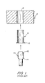
    • FIG. 1 is a disassembled view of a prior art apparatus for cold working a drilled hole.
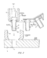
    • FIG. 2 is a sectional view of the present invention illustrating the utilization of an automatic riveting tool for cold working a drill hole.
    • FIG.3 is a partial sectional view of the apparatus shown in FIG. 2 after insertion of an expandable sleeve.
    • FIG. 4 is a diagrammatic illustration of a position sensing device used in conjunction with the present invention.
    • FIG. 5 is a partial sectional view showing the underside of an automatic riveting maching which has been equipped to cold work a drilled hole in accordance with the present invention.
    DETAILED DESCRIPTION OF THE INVENTION
  • In order to appreciate the present invention, reference is made to the basic method set forth in previously mentioned U.S. Patent No. 4,433,567. Referring to FIG. 1, which shows the patented apparatus, hole 2 in metal member 4, for example, of heat treated aluminum alloy, is drilled and reamed to a hole size typically 0.235 inch.
  • Sleeve 6 of Nitinol, (or other memory metal alloy) having a shoulder 8 and a wall thickness of about 0.010 inch is memory shaped in conventional manner to an O.D. of 0.234 inch, placed in a liquid nitrogen bath, where it is cooled to the bath temperature. The cooled sleeve 6, having an O.D. of 0.234 inch, an I.D. of 0.214 inch and a wall thickness of 0.010 inch is inserted into hole 2 of member 4 which may be a single plate or a plurality of plates to be bolted, riveted or otherwise fastened together. Cold sleeve 6 is inserted into hole 2 so that shoulder 8 contacts the surface of member 4. Mandrel 10 which may have tapered ends 12, 14 and a median portion of a diameter of 0.234 inch is inserted into sleeve 6 forced through the center of the sleeve to expand the I.D. of the sleeve to 0.234 inch, the diameter of the mandrel, and the O.D. of the sleeve to 0.255 inch. The expansion of sleeve 6 works and enlarges hole 2 from the drilled and reamed diameter of 0.235 inch to a worked diameter of 0.255 inch. Mandrel 10 is withdrawn and sleeve 6 is allowed to return to room tempera- lure and return to its memory shape of 0.234 inch O.D. dimension. Sleeve 6 is then removed from the worked hole and can be recooled in liquid nitrogen, re-inserted into the next hole drilled and reamed to a hole size of 0.235 inch and again expanded with the mandrel to work the metal around such hole. After expanding and working, sleeve 6 is again allowed to return to room or ambient temperature and return to its initial memory shape and dimensions.
  • The process can be repeated and a number of holes can be worked using the same sleeve and mandrel. Thermal inducement of the sleeve and the returning or shrinking of the sleeve to its original or memory size separates the sleeve from the wall of the worked hole and allows the Nitinol sleeve to be removed without damage to the sleeve or hole wall. Thus, the Nitinol sleeve can be recycled and reused and machining or other finishing of the worked hole is net required.
  • It is, or course, obvious that the hole to be worked may be of a different size than that described above. When the hole to be worked is of a different size, the size of the Nitinol sleeve and the mandrel with which the sleeve will be expanded are sized proportionately. The original or memory size of the O.D. of the Nitinol sleeve should be slightly less than the size of the drilled hole to be worked and less than the size of the hole after working. This assures that the sleeve might be inserted and, when returned to room temperature, withdrawn without damage to the sleeve or hole wall.
  • FIG. 2 illustrates the improvement constituting the present invention which is implemented by the utilization of an automatic riveting machine, such as the DRIVEMATIC automatic riveting machine, which is extensively utilized in the aerospace industry.
  • Mandrel 10 is driven by a RAM of the riveting machine, similar to the action which occurs during the bucking of a rivet with such a machine. Pivotally mounted fingers 16 open and close in and out of the plane of the paper during successive grasping and releasing operations involving serially fed sleeves 6. The sleeves may be fabricated from the same metal as discussed hereinabove, but the shoulder portion 8' includes an annular recess 9 for receiving the lower ends of fingers 16 and the end 20 is tapered. Feed track 18' gravitationally delivers the lowermost sleeve 6 to a point where the fingers 16 may grasp the sleeve and lower it into hole 2. The automatic riveting machine then rams mandrel 10 downwardly through the bore 22 in sleeve 6 thereby plastically deforming it The mandrel 10 is pulled upwardly to remove it from engagement with sleeve 6. At this point, the hole 2 has been satisfactorily cold worked as was the case with the manual plastic deformation set forth in the prior patent Pressure foot 18 clamps the workpiece in position.
  • FIG. 3 illustrates the retention of sleeve 6 in hole 2. After withdrawal of the mandrel, air tube 24, attached to a stationary surface adjacent sleeve 6 becomes operative. In the event sleeve 6 is of a metal which contracts upon heating, the air delivered through tube 24 along stream 26 is heated air. However, sleeve 6 may be made of a metal material which shrinks when cooled, in which event the tube 24 would deliver cold air. After sufficient exposure to the air delivered from tube 24, sleeve 6 shrinks thereby permitting its removal from the work piece 4.
  • FIG. 4 illustrates a simplified block diagram of the electrical components for initiating and termination operation of a blower which forces air, of the desired temperature, through tube 24. A conventional position sensor 28 senses the withdrawal cycle of mandrel 10 resulting in the insertion of sleeve 6 into work piece 4 (FIG. 3). Timer 30 initiates operation of blower 32 for a preset time interval during which time stream 26 (FIG.3) accomplishes shrinking of sleeve 6. After the present time interval, air is no longer blown over the sleeve 6 and the sleeve may be easily removed and reused.
  • FIG. 5 shows an alternate embodiment of the present invention wherein the work application occurs on the bottom side of the work piece 4. Drill 28' mounted in the head of an automatic riveting machine is lowered into engagement with work piece 4 and drills the hole to be cold worked. A lower clamp 30' engages work piece 4 and clamps it against pressure foot 18 so that the work piece is held securely.
  • A lower mechanism 31 of an automatic riveting machine, such as the drivematic, includes a ram mechanism that is capable of displecing mandrel 32' upwardly loward work piece 4. Each sleeve 6 is fed to an upper point of feed tube 34 and shuttle 38, actuated by lever 40, urges each sleeve 6, positioned at shuttle 38, into coaxial alignment with mandrel 32' so that the mandrel may drive sleeve 6 into the hole 2 in work piece 4 and accomplish the plastic expansion discussed in connection with the previous figures. In a typical machine of the type discussed, the feed tube 34 is pneumatically pressured via supply lines 36 to serially feed all of the sleeves located therein.
  • In summary, the present invention is seen to provide a substantial improvement over the prior art method of cold working holes with metal sleeves. By utilizing a multitool machine, such a DRIVEMATIC machine, the method of the present invention may be implemented quickly, at lower cost and repeated reliability.
  • It should be understood that the invention is not limited to the exact details of construction shown and described herein for obvious modifications will occur to persons skilled in the art.

Claims (10)

1. A system for cold working a hole wall formed in a metal workpiece comprising:
means for feeding a plurality of metal sleeves, each having an O.D. less than the diameter of the hole, to a work point;
a mandrel connected to a ram of a multi-tool machine for plastically expanding the sleeve in the hole as the mandrel passes through a bore formed in the sleeve thereby cold working the hole wall;
means for thermally inducement mounted to the machine in a location near the sleeve for shrinking the sleeve thereby permitting its removal from the hole.
2. The system set forth in claim 1 together with fingers pivotally mounted to the machine for grasping a recess formed in each sleeve and enabling the fingers to lower the sleeve into the hole.
3. The system set forth in claim 1 wherein a drill is selectively mounted to the machine for permitting initial drilling of the workpiece to form the hole.
4. The system set forth in claim 1 together with means for sensing the position of the mandrel;
timing means connected to the position sensing means for generating a preset timing interval; and
means connected at an input thereof to the output of the timing means for achieving thermal inducement of the sleeves at a preselected temperature to cause the shrinking thereof.
5. The system set forth in claim 2 together with means for sensing the position of the mandrel;
timing means connected to the position sensing means for generating a preset timing interval; and
means connected at an input thereof to the output of the timing means for achieving thermal inducement of the sleeves at a preselected temperature to cause the shrinking thereof.
6. An automated method for cold working the wall around a hole in a metal member, the method comprising:
drilling a plurality of holes in a workpiece;
serially feeding a plurality of metal sleeves to the location of their respective holes from a feed track;
automatically positioning each sleeve within a respective hole, the outer diameter of each sleeve having a smaller outer diameter than the diameter of the hole;
fitting an automated multi-tool machine with a mandrel;
driving the mandrel through the sleeve thus causing plastic expansion thereof which cold works the wall of the hole;
withdrawing the mandrel from the sleeve;
positioning thermal inducement means at a location adjacent the inserted sleeve;
thermally inducing the sleeve, at a preselected temperature, for shrinking it; and
removing the sleeve from the hole thus permitting its recycling.
7. The method set forth in claim 6 together with the preliminary step of drilling the hole in the workpiece with the machine.
8. The method set forth in claim 6 wherein the sleeve positioning step is performed by pivoting fingers mounted to the machine, the fingers adapted to grasp each sleeve and lower it into a hole.
9. The method set forth in claim 6 wherein the sleeve positioning step is performed by positioning the mandrel below the workpiece and displacing the mandrel upwardly to engage the sleeve and push it into the hole prior to plasti- catty expanding the sleeve therein.
10. The method set forth in claim 6 together with the steps of:
sensing the displacement of the sleeve into the hole;
initiating a timing cycle upon actuation of the sensing step and
thermally inducing the sleeve during the timing cycle.
EP86400052A 1985-01-29 1986-01-10 Automated process for cold working holes Withdrawn EP0191663A3 (en)

Applications Claiming Priority (2)

Application Number Priority Date Filing Date Title
US06/696,230 US4640114A (en) 1985-01-29 1985-01-29 Automated process for cold working holes
US696230 1985-01-29

Publications (2)

Publication Number Publication Date
EP0191663A2 true EP0191663A2 (en) 1986-08-20
EP0191663A3 EP0191663A3 (en) 1988-07-20

Family

ID=24796225

Family Applications (1)

Application Number Title Priority Date Filing Date
EP86400052A Withdrawn EP0191663A3 (en) 1985-01-29 1986-01-10 Automated process for cold working holes

Country Status (7)

Country Link
US (1) US4640114A (en)
EP (1) EP0191663A3 (en)
JP (1) JPS61176438A (en)
AU (1) AU580104B2 (en)
BR (1) BR8600208A (en)
CA (1) CA1251061A (en)
IL (1) IL76951A (en)

Cited By (3)

* Cited by examiner, † Cited by third party
Publication number Priority date Publication date Assignee Title
GB2314854A (en) * 1996-07-02 1998-01-14 Gkn Westland Helicopters Ltd Assembling a hardened metallic component in an opening in a composite structure
WO1998047658A2 (en) * 1997-04-18 1998-10-29 Huck International, Inc. Control system for an assembly tool
EP2412480A3 (en) * 2010-07-27 2013-01-09 Rolls-Royce plc A Tool

Families Citing this family (5)

* Cited by examiner, † Cited by third party
Publication number Priority date Publication date Assignee Title
US4869091A (en) * 1988-03-22 1989-09-26 The Boeing Company Tool for coldworking holes
US5305627A (en) * 1992-07-27 1994-04-26 Fatigue Technology, Inc. Split sleeve cold expansion
US5613395A (en) * 1995-02-09 1997-03-25 Gemcor Engineering Corp. Coldworking tool automation
US7188506B2 (en) * 2004-04-21 2007-03-13 Northrop Grumman Corporation Apparatus and method utilizing an automated machine tool system and mandrel for cold working of holes in metal components
US8869373B2 (en) * 2010-07-02 2014-10-28 Lear Corporation Arbor insertion tool

Citations (5)

* Cited by examiner, † Cited by third party
Publication number Priority date Publication date Assignee Title
FR2102190A1 (en) * 1970-08-11 1972-04-07 Jaffe David
US3943748A (en) * 1973-01-17 1976-03-16 King John O Jun Coldwork system with delay split sleeve
US4180195A (en) * 1978-01-16 1979-12-25 The Boeing Company Rivet delivery and locating apparatus
EP0028809A1 (en) * 1979-11-08 1981-05-20 Theo Cyron Methods and devices for rolling-in tubes coated on the interior
EP0115662A1 (en) * 1981-11-12 1984-08-15 Grumman Aerospace Corporation Method for working holes

Family Cites Families (25)

* Cited by examiner, † Cited by third party
Publication number Priority date Publication date Assignee Title
US418341A (en) * 1889-12-31 Machine for attaching metal plates
US405929A (en) * 1889-06-25 unbehend
US1240207A (en) * 1917-01-26 1917-09-18 Henry C Hinchcliff Punching and setting machine.
US1737010A (en) * 1924-10-31 1929-11-26 Hanna Engineering Works Timing and reversing mechanism
US1901375A (en) * 1931-04-08 1933-03-14 Patent Button Co Button attaching machine
US1976776A (en) * 1932-01-07 1934-10-16 United Shoe Machinery Corp Eyelet
US2185483A (en) * 1938-04-06 1940-01-02 Frank T Ward Method of preparing high manganese steel members and the product thereof
US2193084A (en) * 1939-02-23 1940-03-12 Cool Moore Corp Shoe heeling machine
US2361668A (en) * 1941-02-17 1944-10-31 George F Wales Method of connecting elements of punching units
US2373436A (en) * 1943-03-18 1945-04-10 Scovill Manufacturing Co Fastener setting or attaching machine
US2843174A (en) * 1953-01-21 1958-07-15 Douglas Aircraft Co Inc Rattle type dimple gun with tool and work heating means
US3092714A (en) * 1961-06-15 1963-06-04 Hinden Milton Welding apparatus
US3151330A (en) * 1962-02-13 1964-10-06 Gen Am Transport Tools for driving thin-walled metal ferrules
US3456483A (en) * 1966-06-28 1969-07-22 Thomas Industries Inc Anvil device
US3566662A (en) * 1969-04-28 1971-03-02 Boeing Co Coldworking method and apparatus
US3640655A (en) * 1970-02-25 1972-02-08 Mite Corp Apparatus for utilizing hot and cool gas for thrust embedding a metal insert in a body of heat softenable material
US3849864A (en) * 1971-05-27 1974-11-26 Plummer Walter A Method of making bellows
BE788517A (en) * 1971-09-07 1973-03-07 Raychem Corp VERY LOW TEMPERATURE CHUCK EXPANSION PROCESS
US3756051A (en) * 1972-03-22 1973-09-04 Budd Co Lubricating system for metal forming die
US3812568A (en) * 1973-02-12 1974-05-28 Vip Machinery Inc Apparatus for the application of shrink tubing
US3816895A (en) * 1973-03-14 1974-06-18 Trw Inc Chuck assembly for fasteners
GB1458672A (en) * 1973-07-19 1976-12-15 Psm Fasteners Ltd Installing inserts
JPS5315008U (en) * 1976-07-20 1978-02-08
FR2359659A1 (en) * 1976-07-30 1978-02-24 Itw De France APPARATUS FOR LAYING RIVETS OR SIMILAR STRIP-FEED FASTENERS
US4528733A (en) * 1983-07-25 1985-07-16 United Aircraft Products, Inc. Method of making tubular heat exchangers

Patent Citations (5)

* Cited by examiner, † Cited by third party
Publication number Priority date Publication date Assignee Title
FR2102190A1 (en) * 1970-08-11 1972-04-07 Jaffe David
US3943748A (en) * 1973-01-17 1976-03-16 King John O Jun Coldwork system with delay split sleeve
US4180195A (en) * 1978-01-16 1979-12-25 The Boeing Company Rivet delivery and locating apparatus
EP0028809A1 (en) * 1979-11-08 1981-05-20 Theo Cyron Methods and devices for rolling-in tubes coated on the interior
EP0115662A1 (en) * 1981-11-12 1984-08-15 Grumman Aerospace Corporation Method for working holes

Cited By (5)

* Cited by examiner, † Cited by third party
Publication number Priority date Publication date Assignee Title
GB2314854A (en) * 1996-07-02 1998-01-14 Gkn Westland Helicopters Ltd Assembling a hardened metallic component in an opening in a composite structure
WO1998047658A2 (en) * 1997-04-18 1998-10-29 Huck International, Inc. Control system for an assembly tool
WO1998047658A3 (en) * 1997-04-18 1999-01-28 Huck Int Inc Control system for an assembly tool
US6058598A (en) * 1997-04-18 2000-05-09 Huck International, Inc. Control system for an assembly tool
EP2412480A3 (en) * 2010-07-27 2013-01-09 Rolls-Royce plc A Tool

Also Published As

Publication number Publication date
IL76951A (en) 1987-10-30
BR8600208A (en) 1986-09-30
US4640114A (en) 1987-02-03
AU4923385A (en) 1986-08-07
EP0191663A3 (en) 1988-07-20
CA1251061A (en) 1989-03-14
IL76951A0 (en) 1986-04-29
JPS61176438A (en) 1986-08-08
AU580104B2 (en) 1988-12-22

Similar Documents

Publication Publication Date Title
EP0115662B1 (en) Method for working holes
US4640114A (en) Automated process for cold working holes
US6425829B1 (en) Threaded load transferring attachment
CA1037749A (en) Blind rivet and improved method of blind riveting
US5265456A (en) Method of cold working holes using a shape memory alloy tool
EP0766011B1 (en) Blind rivet
ATE233622T1 (en) METHOD, DEVICE AND AUXILIARY JOINING PART FOR MECHANICAL JOINING
US4869091A (en) Tool for coldworking holes
US20070157461A1 (en) Manufacturing Facility for Manufacturing a Fatigue Life Enhanced Airframe
JPS63290645A (en) Device and method boring, countersinking and reveting while being automatically controlled by coupling element consisting of at least two section
EP0572513B1 (en) Method, rivet-punch, rivet, etc. for joining several metal sheets by using non-heat-treating rivets made from an aluminium alloy
JP2500225B2 (en) Piercing molding method and device
US5842267A (en) Method and apparatus for forming parts of a predetermined shape from a continuous stock material
CA2012152A1 (en) Method and apparatus for pull-through blind installation of a tubular member
US4715203A (en) Cold-working tool
JP2000513791A (en) Driving self-penetrating rivets
US6568062B1 (en) Methods of removing self-piercing rivets set into a workpiece and devices for implementing the methods
US3585832A (en) Metal working
US20030082025A1 (en) Blind fasteners and installation methods and apparatus
US3269167A (en) Forging
US6138491A (en) Apparatus and method for low heat transfer rate chill down during forging
US6799450B2 (en) Method of stretch forming an aluminum metal sheet and handling equipment for doing the same
USH419H (en) Contoured punch tool for removing semi-tubular rivets
US3222911A (en) Flexible overlay forming
US2749610A (en) Method and machine for making shackles

Legal Events

Date Code Title Description
PUAI Public reference made under article 153(3) epc to a published international application that has entered the european phase

Free format text: ORIGINAL CODE: 0009012

AK Designated contracting states

Kind code of ref document: A2

Designated state(s): DE FR GB IT SE

PUAL Search report despatched

Free format text: ORIGINAL CODE: 0009013

AK Designated contracting states

Kind code of ref document: A3

Designated state(s): DE FR GB IT SE

17P Request for examination filed

Effective date: 19881212

17Q First examination report despatched

Effective date: 19891106

STAA Information on the status of an ep patent application or granted ep patent

Free format text: STATUS: THE APPLICATION IS DEEMED TO BE WITHDRAWN

18D Application deemed to be withdrawn

Effective date: 19900317

RIN1 Information on inventor provided before grant (corrected)

Inventor name: KULESS, MADELINE A.