EP0189329A2 - A tunneling catheter system for transluminal arterial angioplasty - Google Patents
A tunneling catheter system for transluminal arterial angioplasty Download PDFInfo
- Publication number
- EP0189329A2 EP0189329A2 EP86300490A EP86300490A EP0189329A2 EP 0189329 A2 EP0189329 A2 EP 0189329A2 EP 86300490 A EP86300490 A EP 86300490A EP 86300490 A EP86300490 A EP 86300490A EP 0189329 A2 EP0189329 A2 EP 0189329A2
- Authority
- EP
- European Patent Office
- Prior art keywords
- tunneling
- catheter
- centering
- distal
- cutting
- Prior art date
- Legal status (The legal status is an assumption and is not a legal conclusion. Google has not performed a legal analysis and makes no representation as to the accuracy of the status listed.)
- Withdrawn
Links
Images


Classifications
-
- A—HUMAN NECESSITIES
- A61—MEDICAL OR VETERINARY SCIENCE; HYGIENE
- A61B—DIAGNOSIS; SURGERY; IDENTIFICATION
- A61B17/00—Surgical instruments, devices or methods, e.g. tourniquets
- A61B17/22—Implements for squeezing-off ulcers or the like on the inside of inner organs of the body; Implements for scraping-out cavities of body organs, e.g. bones; Calculus removers; Calculus smashing apparatus; Apparatus for removing obstructions in blood vessels, not otherwise provided for
- A61B17/22004—Implements for squeezing-off ulcers or the like on the inside of inner organs of the body; Implements for scraping-out cavities of body organs, e.g. bones; Calculus removers; Calculus smashing apparatus; Apparatus for removing obstructions in blood vessels, not otherwise provided for using mechanical vibrations, e.g. ultrasonic shock waves
- A61B17/22012—Implements for squeezing-off ulcers or the like on the inside of inner organs of the body; Implements for scraping-out cavities of body organs, e.g. bones; Calculus removers; Calculus smashing apparatus; Apparatus for removing obstructions in blood vessels, not otherwise provided for using mechanical vibrations, e.g. ultrasonic shock waves in direct contact with, or very close to, the obstruction or concrement
-
- A—HUMAN NECESSITIES
- A61—MEDICAL OR VETERINARY SCIENCE; HYGIENE
- A61B—DIAGNOSIS; SURGERY; IDENTIFICATION
- A61B18/00—Surgical instruments, devices or methods for transferring non-mechanical forms of energy to or from the body
- A61B18/04—Surgical instruments, devices or methods for transferring non-mechanical forms of energy to or from the body by heating
- A61B18/12—Surgical instruments, devices or methods for transferring non-mechanical forms of energy to or from the body by heating by passing a current through the tissue to be heated, e.g. high-frequency current
- A61B18/14—Probes or electrodes therefor
- A61B18/1492—Probes or electrodes therefor having a flexible, catheter-like structure, e.g. for heart ablation
-
- A—HUMAN NECESSITIES
- A61—MEDICAL OR VETERINARY SCIENCE; HYGIENE
- A61B—DIAGNOSIS; SURGERY; IDENTIFICATION
- A61B18/00—Surgical instruments, devices or methods for transferring non-mechanical forms of energy to or from the body
- A61B18/18—Surgical instruments, devices or methods for transferring non-mechanical forms of energy to or from the body by applying electromagnetic radiation, e.g. microwaves
- A61B18/20—Surgical instruments, devices or methods for transferring non-mechanical forms of energy to or from the body by applying electromagnetic radiation, e.g. microwaves using laser
- A61B18/22—Surgical instruments, devices or methods for transferring non-mechanical forms of energy to or from the body by applying electromagnetic radiation, e.g. microwaves using laser the beam being directed along or through a flexible conduit, e.g. an optical fibre; Couplings or hand-pieces therefor
- A61B18/24—Surgical instruments, devices or methods for transferring non-mechanical forms of energy to or from the body by applying electromagnetic radiation, e.g. microwaves using laser the beam being directed along or through a flexible conduit, e.g. an optical fibre; Couplings or hand-pieces therefor with a catheter
- A61B18/245—Surgical instruments, devices or methods for transferring non-mechanical forms of energy to or from the body by applying electromagnetic radiation, e.g. microwaves using laser the beam being directed along or through a flexible conduit, e.g. an optical fibre; Couplings or hand-pieces therefor with a catheter for removing obstructions in blood vessels or calculi
-
- A—HUMAN NECESSITIES
- A61—MEDICAL OR VETERINARY SCIENCE; HYGIENE
- A61B—DIAGNOSIS; SURGERY; IDENTIFICATION
- A61B17/00—Surgical instruments, devices or methods, e.g. tourniquets
- A61B17/00234—Surgical instruments, devices or methods, e.g. tourniquets for minimally invasive surgery
- A61B2017/00292—Surgical instruments, devices or methods, e.g. tourniquets for minimally invasive surgery mounted on or guided by flexible, e.g. catheter-like, means
-
- A—HUMAN NECESSITIES
- A61—MEDICAL OR VETERINARY SCIENCE; HYGIENE
- A61B—DIAGNOSIS; SURGERY; IDENTIFICATION
- A61B17/00—Surgical instruments, devices or methods, e.g. tourniquets
- A61B2017/00831—Material properties
- A61B2017/0084—Material properties low friction
- A61B2017/00849—Material properties low friction with respect to tissue, e.g. hollow organs
-
- A—HUMAN NECESSITIES
- A61—MEDICAL OR VETERINARY SCIENCE; HYGIENE
- A61B—DIAGNOSIS; SURGERY; IDENTIFICATION
- A61B18/00—Surgical instruments, devices or methods for transferring non-mechanical forms of energy to or from the body
- A61B2018/00053—Mechanical features of the instrument of device
- A61B2018/00214—Expandable means emitting energy, e.g. by elements carried thereon
-
- A—HUMAN NECESSITIES
- A61—MEDICAL OR VETERINARY SCIENCE; HYGIENE
- A61B—DIAGNOSIS; SURGERY; IDENTIFICATION
- A61B18/00—Surgical instruments, devices or methods for transferring non-mechanical forms of energy to or from the body
- A61B2018/00315—Surgical instruments, devices or methods for transferring non-mechanical forms of energy to or from the body for treatment of particular body parts
- A61B2018/00345—Vascular system
- A61B2018/00351—Heart
- A61B2018/00386—Coronary vessels
-
- A—HUMAN NECESSITIES
- A61—MEDICAL OR VETERINARY SCIENCE; HYGIENE
- A61B—DIAGNOSIS; SURGERY; IDENTIFICATION
- A61B18/00—Surgical instruments, devices or methods for transferring non-mechanical forms of energy to or from the body
- A61B2018/00315—Surgical instruments, devices or methods for transferring non-mechanical forms of energy to or from the body for treatment of particular body parts
- A61B2018/00345—Vascular system
- A61B2018/00404—Blood vessels other than those in or around the heart
-
- A—HUMAN NECESSITIES
- A61—MEDICAL OR VETERINARY SCIENCE; HYGIENE
- A61B—DIAGNOSIS; SURGERY; IDENTIFICATION
- A61B2217/00—General characteristics of surgical instruments
- A61B2217/002—Auxiliary appliance
- A61B2217/005—Auxiliary appliance with suction drainage system
Landscapes
- Health & Medical Sciences (AREA)
- Life Sciences & Earth Sciences (AREA)
- Surgery (AREA)
- Engineering & Computer Science (AREA)
- General Health & Medical Sciences (AREA)
- Nuclear Medicine, Radiotherapy & Molecular Imaging (AREA)
- Public Health (AREA)
- Physics & Mathematics (AREA)
- Veterinary Medicine (AREA)
- Animal Behavior & Ethology (AREA)
- Biomedical Technology (AREA)
- Heart & Thoracic Surgery (AREA)
- Medical Informatics (AREA)
- Molecular Biology (AREA)
- Otolaryngology (AREA)
- Vascular Medicine (AREA)
- Electromagnetism (AREA)
- Optics & Photonics (AREA)
- Mechanical Engineering (AREA)
- Orthopedic Medicine & Surgery (AREA)
- Cardiology (AREA)
- Plasma & Fusion (AREA)
- Media Introduction/Drainage Providing Device (AREA)
- Surgical Instruments (AREA)
Abstract
® A tunneling catheter system for percutaneous transluminal angioplasty which includes a catheter for advancement through a patient's arterial system to the vicinity of an arterial stenosis and tunneling means disposed within the catheter for tunneling through the arterial stenosis. Means for centering the catheter and for various methods of tunneling through the catheter are also provided.
Description
- This invention is generally in the field of catheters to accomplish arterial, transluminal angioplasty and more specifically, is a catheter system for tunneling a lumen through an arterial occlusion or near occlusion so that the blood flow through that artery can be significantly increased.
- Atherosclerotic arterial disease is the leading cause of morbidity and mortality in the United States and most other developed countries. Atherosclerosis is a chronic disease process characterized by lipid deposits and fibrosis of the intima, irregularly distributed in large and medium sized arteries. The disease is progressive and most often becomes clinically manifest in the middle-aged and elderly. When severe, the atherosclerotic plaque causes a reduction of the cross sectional area of the arterial lumen, with or without thrombosis. Resultant ischemic manifestations include: angina pectoris, myocardial infarction, stroke, intermittent claudication, gangrene of the lower extremities and renovascular hypertension.
- The current management of atherosclerotic disease includes preventative therapy aimed at minimizing known major risk factors such as hypertension, smoking, hypercholesterolemia and diabetes mellitus.
- Coronary artery bypass grafting (CABG), carotid enderterectomy and bypass grafting (autogenous vein or synthetic graft) of the iliac, femoral and renal arteries are all well established surgical methods of palliative therapy. Although these procedures are often effective in relieving ischemia, each of these represents a major surgical operation with significant associated morbidity, mortality and expense. CABG, for example, requires the opening of the chest cavity (thoracotomy) and use of cardiopulmonary bypass, with not uncommon postoperative complications including postpericardotomy syndrome, Non-A Non-B hepatitis, stroke and a mortality of approximately one percent (1%) at most centers.
- Percutaneous transluminal angioplasty (PTA) by means of a balloon catheter is a relatively new ("non-surgical") procedure with proven efficacy in the relief of atherosclerotic obstruction of the coronary, renal and peripheral arterial circulations. The technique involves the percutaneous passage (under local anesthesia) of a specialized balloon-tipped catheter through the site of arterial narrowing, and inflation of the balloon to reduce the obstruction. This is always done in conjunction with angiographic visualization of the vessel being treated. When successful, this procedure results in a reduction of the arterial stenosis and a decrease in the transstenotic pressure gradient. The mechanism of action is felt to consist of some combination of plaque compression, intimal splitting and medial/adventitial stretching. Healing of the balloon-damaged plaque may involve fibrosis and retraction of the split intimal elements, with further luminal enlargement in the weeks to months following the procedure.
- The safety and efficacy of PTA is a function of the vessel being treated, patient selection, and the expertise of the physician performing the procedure. Primary angiographic success, defined as a 20% or greater reduction of stenosis, is now achieved in approximately 80-90% of attempts in carefully selected patients at experienced Centers. The obvious advantage of PTA, compared to surgical palliative therapy, is that it does not require major surgery or general anesthesia with their associated sequelae.
- Despite its proven efficacy in the palliation of obstructive atherosclerotic disease, PTA, as it is currently performed, has several important technical limitations. These limitations are particularly true in the application of PTA to the coronary circulation.
- Even in the most skilled hands, dilation of an arterial obstruction is currently not achievable in approximately 20% of attempts. The most common cause of failed PTA is the inability to pass either the guide wire or dilating catheter through the site of a tight or eccentric stenosis. This problem is even more common in attempts to dilate the difficult to access right and circumflex coronary arteries. Although technical advances, such as steerable catheters, have reduced the frequency of unsuccessful attempts, inability to cross a tight, eccentric or fully closed stenosis remains a major limitation of PTA.
- Attempts at balloon or guide wire passage in vessels which are tightly stenotic may lead to arterial dissection and/or acute occlusion necessitating emergency vascular surgery. This major complication occurs in 6-8% of attempts at coronary angioplasty.
- Inability to dilate an obstruction, even after proper balloon positioning and inflation is a second common mode of PTA failure. This problem is most frequently encountered in older plaques which are densely fibrotic and/or calcified.
- Restenosis of the obstructed arterial segment following successful PTA is a major problem with the current technique. This problem is more common following PTA of a coronary obstruction (30-35% at one year) than in the peripheral circulation (10-15% at two years). Pharmacologic attempts to reduce the incidence of restenosis have been largely unsuccessful.
- Distal embolization of atherosclerotic plaque following balloon PTA occurs in approximately 5% of patients undergoing PTA of lower extremity or renal arteries. Although these emboli are usually clinically insignificant in these vascular territories, such embolization could be catastrophic in the cerebral circulation. For this reason, balloon PTA is considered to be contraindicated for the treatment of obstructive lesions in the arteries of the aortic arch, such as the carotid artery.
- In U.S. Patent 4,207,874 (dated June 17, 1980) D.S.J. Choy describes a means for using a laser beam to tunnel through an arterial occlusion by vaporization of the obstruction. The difficulty with Choy's invention is that there is insufficient means to prevent simultaneous destruction of the arterial wall. For example, the Choy invention shows an intense laser beam directed in the forward direction without significant beam attenuation in that direction. If the artery were to curve and the arterial wall was exposed to the laser beam, the wall could also be vaporized which could be a catastrophic result for the patient. Although the Choy invention describes a means for direct visualization of the obstructed region, it does not describe a centering means to guarantee that the laser beam does not illuminate part of the arterial wall. Furthermore, the Choy invention may completely obstruct a partially obstructed artery thereby cutting off blood flow to distal tissues for a significant time period. The result is ischemia which could cause irreparable damage to heart or brain tissue.
- In U.S. Patent 4,273,128 (dated June 16, 1981) B. G. Lary describes a "Coronary Cutting and Dilating Instrument" used for opening a coronary stenosis that is restricting blood flow. The device described by Lary could not be used in a completely occluded artery because its "blunt ovoid tip" could not pass through a completely occluded vessel. Furthermore, the Lary invention does not have any means to prevent its cutting blade from cutting through the arterial wall as well as the occluding stenosic material. Furthermore, there is no means taught in the Lary patent for centering the cutting blade within the arterial walls. Thus, if the probe wire 13 (of FIG. 10) of the Lary invention guides the knife through a highly eccentric lumen within the stenotic plaque, its knife blade would surely cut through the arterial wall which would have serious adverse effects for the patient.
- Thus, it is the goal of the present invention to eliminate the numerous shortcomings of the prior art in order to provide a device which can safely tunnel a clean hole through a partially or fully occluded arterial stenosis even if the narrowed stenotic passage is located eccentrically within the arterial wall.
- The tunneling angioplasty catheter system described herein is capable of being placed within an arterial lumen and then advanced until it is in contact with an occlusion. The centering catheter (of the catheter system) is then expanded until its spokes engage the inner arterial wall just proximal to the occlusion. The expanding "spokes provide a centering means for a tunneling catheter. With the aid of biplanar, image intensified x-ray fluoroscopy, the tunneling catheter is then advanced into the plaque which forms the arterial occlusion. The tunneling catheter is generally in the shape of a hollow cylinder with a sharp circular cutting edge. A bore cylinder of the plaque is caused to enter an interior volume of the advancing tunneling catheter. The bore cylinder is held in place in that volume by means of a suction applied at the proximal end of the tunneling catheter whose hollow lumen is in fluid communication with the distal end of the catheter. When the tunneling catheter is removed from the body the bore cylinder of plaque is also removed, thus opening the arterial lumen.
- Several methods are possible to promote cutting by the sharpened distal end which is the cutting edge of the cylindrical tunneling catheter. One method is merely to advance the extremely sharp distal cutting edge; another method is to rotate the tunneling catheter's cutting edge as it is advanced. Another method is to apply a high energy ultrasonic vibration into the tunneling catheter from its proximal end causing the sound energy to be readily transmitted by conduction into the catheter's cutting edge. Another method for deftly cutting through the plaque is by applying an electrocautery alternating current to the cutting edge. Still another method is by the use of a fiber optic through which is transmitted a high energy laser light beam which is used to vaporize the plaque within the tunneling catheter's distal interior volume.
- Once a tunnel has been made in the plaque, a balloon angioplasty catheter could be advanced into the partially opened occlusion. The balloon can then be expanded to further dilate the opening as is well known in the art of percutaneous, transluminal balloon angioplasty. The tunnel that is bored in the plaque may be of sufficient diameter itself to allow adequate blood flow without the subsequent use of an angioplasty balloon catheter.
- Thus an object of this invention is to tunnel a hole through an arterial occlusion, particularly an occlusion that is nearly fully or totally occluded or which has its narrowed passageway eccentrically located relative to the center of the arterial lumen.
- Another object of this invention is to first use a tunneling catheter system to bore a tunnel into the plaque and then use a balloon angioplasty catheter to further enlarge the lumen of the occluding plaque.
- Still another object of the present invention is to employ a sharpened, cylindrical edge of a tunneling catheter to cut through the plaque.
- Still another object of the present invention is to utilize ultrasonic vibration of the cylindrical cutting edge to facilitate its ability to cut through the plaque.
- Still another object of the present invention is to utilize an electrocautery to apply an electric current to the cutting edge of the tunneling catheter to enhance its ability to cut through the occlusion.
- Still another object of the present invention is to utilize a carefully guided fiber optic through which a laser light beam transmitted to vaporize plaque that is within an interior volume at the distal end of the tunneling catheter.
- Still another object of the present invention is to apply this technique to any occluded artery including the coronary arteries, the carotid artery, the renal artery and the arteries of the legs and arms.
- Other objects, features and advantages of the present invention will be apparent from the following descriptions considered in conjunction with the several drawings which collectively form the specification of this invention.
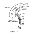
- FIG. 1 illustrates a system of catheters placed through the lumen of the aorta into the left coronary artery.
- FIG. 2 illustrates the distal end of the centering catheter in its expanded position.
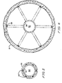
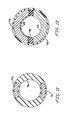
- FIG. 3 shows the cross-section of the centering catheter at a point where the unextended spokes are within the outside tube of the centering catheter.
- FIG. 4 shows the cross-section of the distal end of the centering catheter showing how the spokes engage the interior surface of the arterial wall.
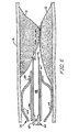
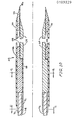
- FIG. 5 illustrates one embodiment of the tunneling catheter within the inside tube of the centering catheter as it is positioned to tunnel through a nearly fully occluded segment within an artery.
- FIG. 6 shows an alternative embodiment of the tunneling catheter specifically showing the design for the distal tip of a tunneling catheter that could utilize an electrocautery current to enhance its ability to cut through plaque.
- FIG. 7 shows the cross-section of the connecting wires for the electrocautery tunneling catheter of FIG. 6.
- FIG. 8 shows the cross-section near the distal end of the electrocautery tunneling catheter of FIG. 6.
- FIG. 9 illustrates the synchronous application of electrocautery current with the refractory period of the heart.
- FIG. 10 illustrates a bipolar electrocautery tunneling catheter.
- FIG. 11 shows the cross-section of the connecting wires to the electrocautery catheter of FIG. 10.
- FIG. 12 shows the cross-section near the distal end of the electrocautery tunneling catheter of FIG. 10 illustrating how the two electrodes are electrically insulated from each other.
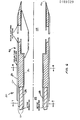
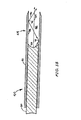
- FIG. 13 shows another alternative embodiment of the tunneling catheter that would employ a fiber optic to cause a divergent laser beam to be transmitted inside the distal interior volume of the tunneling catheter in order to vaporize the plaque in that region.
- FIG. 14 is a cross sectional view of the proximal portion of the catheter system illustrating the means for inserting the centering catheter and expanding its spokes and for inserting and advancing the tunneling catheter.
- FIG. 15 is a top view of that portion of the proximal end of the catheter system that is used to adjust the diameter of the spokes of the centering catheter by pulling back on the outside tube of the centering catheter relative to its inside tube.
- FIG. 16 is a top view of that portion of the proximal end of the catheter system that is used to set the stroke length for tunneling through the plaque by means of a tunneling catheter.
- FIG. 1 shows the configuration of several catheters as they pass from the ascending aorta AA into the left coronary artery LCA. To accomplish this, a surgical incision is typically made in the upper portion of the right leg where access to the femoral artery can be accomplished. The guiding
catheter 10 is then transluminally advanced through the descending aorta, then into the ascending aorta AA and finally entering the left coronary artery LCA. Of course, it is well known in the medical art to place such a guiding catheter into a large variety of arteries including the heart's posterior descending or circumflex arteries, or the carotid, femoral, renal or any other artery in which a stenotic condition can occur. Thus, although this specification will specifically describe tunneling through a coronary artery, it is also within the teachings of this invention to utilize the techniques described herein for opening of any of the arteries of the body of a human subject or any other living organism that suffers the affliction of arterial occlusions. - Returning.now to FIG. 1, once the guiding
catheter 10 has been placed in the left coronary artery LCA, a centeringcatheter 20 having anoutside tube 22 is advanced through the guidingcatheter 10 until its distal end is stopped by the occlusion. Thespokes 24 of the centeringcatheter 20 are then extended to engage the artery's interior surface using the proximal portion of the apparatus shown in FIGS. 14, 15, and 16. A radio-opaque substance is then transmitted through the guiding catheter to better define the site of the occlusion. This occlusion would undoubtedly have been found from a prior angiographic study, so that its location would actually be reconfirmed. prior to the tunneling activity. Atunneling catheter 40 is then advanced through theinside tube 26 of the centeringcatheter 20 until the forward motion of the tunneling catheter is also stopped by the occlusion. Using biplanar, image intensified x-ray fluoroscopy, the accurate centering of the tunneling catheter is verified and the length of the occlusion is accurately determined. The proximal portion of this system for tunneling angioplasty (shown in FIGS. 14, 15, and 16) is then used to set the stroke length for the tunnel that is to be bored in the occlusion. The tunneling catheter is then advanced by that length, and a bore cylinder or bore volume is removed. Angiography can then be utilized to determine if the tunnelled lumen is sufficiently large to allow adequate blood flow. If it is, the procedure would be terminated. If not, a balloon angioplasty catheter could be advanced into the tunneled lumen and then expanded to further increase the flow of blood. Since the tunneled lumen prior to insertion of a balloon catheter would be of reasonable size and centrally located within the artery, use of the balloon angioplasty technique at that point would not be difficult. - FIG. 2 shows the distal end of the centering
catheter 20 within the unobstructed artery A with the centeringcatheter 20 having itsspokes 24 extended to engage the artery's interior surface. When the centeringcatheter 20 is first advanced through the guidingcatheter 10, thespokes 24 and theinside tube 26 are located entirely within theoutside tube 22 with their distal ends at the same point. The proximal portion of this tunneling catheter system is then used to pull theoutside tube 22 back until thespokes 24 are uncovered. As thespokes 24 move out, aslide ring 25 slides back along theinside tube 26 until thespokes 24 securely engage the interior surface of the arterial wall. At that point, theinside tube 26 will be centered within the unoccluded artery A. This can be further verified by fluoroscopy prior to proceeding with the tunneling. Thespokes 24 have anattachment 28 to theinside tube 26 at their proximal end and have an attachment 30 to theslide ring 25 at thespokes 24 distal end. The region of theinside tube 26 that is in contact with thespokes 24 could be a collection of wires with one wire for each spoke. This construction would provide improved flexibility for passing through curving coronary arteries. - A
lumen 32 within theinside tube 26 is used to pass the tunnelingcatheter 40. FIGS. 3 and 4 show cross-sections of the centeringcatheter 20. FIG. 3 shows the cross-section of the centeringcatheter 20 within theoutside tube 22 as indicated by 3-3 of FIG. 2. FIG. 4 shows the cross-section of the centeringcatheter 20 at 4-4 of FIG. 2 showing thespokes 24 extended. Although 6 spokes are shown, 3 to 8 spokes could also be used for this centering purpose. This spoke design is such that each spoke 24 deploys with the same radial displacement for the same length of pull-back of theoutside tube 22 relative to theinside tube 26. Hence, theinside tube 26 will be accurately centered within the artery A. However, the exact centering would be confirmed by fluoroscopy before tunneling would be attempted. - FIG. 5 shows the distal end of the centering
catheter 20 located within an artery A just proximal to an occlusion O. A narrow and slightly eccentric lumen L is shown in the occlusion O. Thespokes 24 have been extended to engage the interior surface of the artery A. Atunneling catheter 40 is shown protruding from theinside tube 26 of the centeringcatheter 20. Thetunneling catheter 40 has acutting edge 46, adistal section 44 containing atunneling cavity 48 in fluid communication with aninterior lumen 52 contained within thetunneling catheter tube 42. When thetunneling catheter 40 is advanced into the occlusion O, itscutting edge 46 will remove abore volume 50 from the occlusion O. Because thespokes 24 allow blood flow through the restricted lumen L, which would not be the case if a balloon was used for centering, the doctor can work slowly and carefully to be sure that everything is properly positioned before the tunneling process is started. Furthermore, although thedistal end 44 of thetunneling catheter 40 could possibly fully (or nearly fully occlude) blood flow while it is boring, its cutting action and retraction back into theinside tube 26 of centering catheter can be accomplished in a few seconds, thus, damaging ischemia of the distal tissue would be avoided. Of course, the technique described above would work equally well for an occlusion that had no opening whatsoever. - The
distal end 44 of thetunneling catheter 40 can cut when itssharp edge 46 is advanced into a plaque or thrombotic occlusion. However, the cutting action can be improved by rotating thesharp edge 46 as it advances. This can be accomplished by rotation of a portion of the proximal end (outside the body) of the catheter system as will be described in the explanation of FIG. 14. - If a source of ultrasonic vibration is applied at the proximal end of the
tunneling catheter 40, the sound energy will be transmitted to thecutting edge 46 thereby enhancing its ability to readily cut through even a calcified occlusion. This application of ultrasonic energy from the proximal end (outside the body) of thetunneling catheter 40 will be further explained herein with the aid of FIG. 14. - The centering
catheter 20 would typically have its outside tube made from a plastic material such as teflon, nylon, or polyvinyl chloride. The outside diameter of the centeringcatheter 20 would vary according to the need for accessing different size arteries. The largest diameter might be 3 mm for clearing occlusions in the femoral artery in the leg; the smallest might be 1 mm outside diameter for entering a small coronary artery. The wall thickness of theoutside tube 22 would typically be 0.2 mm for the largest catheters and 0.1 mm for the smallest. Theinside tube 26 would be made to just pass inside theoutside tube 22 and might be made of the same plastic materials. However, it may be desirable to make at least the distal end of theinside tube 26 out of 316 stainless steel with a wall thickness of approximately 0.05 mm. Thespokes 24 would be made from 316 stainless steel with a thickness of approximately 0.1 mm and a width of 0.2 to 1.0 mm, depending on the diameter of theinside tube 26. Thespokes 24 would be approximately 5 cm in total length. Theslide ring 25 would have a thickness of approximately 0.1 mm, a length of approximately 1.0 mm, and a diameter that just fits around the outside surface of theinside tube 26. Thedistal end 44 of thetunneling catheter 40 would be made of 316 stainless steel for a length of about 2 cm. Thetunneling catheter tube 42 may be made from a plastic material such as that used for theoutside tube 22 of the centering catheter, or from a flexible piece of hollow 316 stainless steel wire, or from combinations of both materials. - The length of the guiding
catheter 10, the centeringcatheter 20 and thetunneling catheter 40 would be approximately 120 cm. - FIG. 6 shows the
distal end 44 of atunneling catheter 40 that can utilize an electrocautery cutting electric current at itssharp edge 46 to enhance the cutting action through an occlusion. An active, metallic cuttingelectrode 54 is conformal coated withelectrical insulation 56 on its interior surface, and a thin,Teflon insulation 62 is placed around its exterior surface. The distal end is made into asharp cutting edge 46. At the proximal end of theelectrode 54 there are connected twoelectrical conductors 58 that are inside a cylindrically shapedelectrical insulation 60. The proximal ends of theconductors 58 are connected to one terminal of an electrocautery current generating device (not shown) that is well known in the art. The other terminal of the electrocautery current generator is connected to a large area, indifferent (grounded) plate (not shown) that makes electrical contact with the patient's skin. Thus, the high concentration of electrocautery current will be at thesharp cutting edge 46 which provides effective cutting and cauterization as thesharp cutting edge 46 of thetunneling catheter 40 is advanced through the occlusion. - FIGS. 7 and 8 show cross sections of the
electrocautery tunneling catheter 40 at 7-7 and 8-8 respectively of FIG. 6. - If the
electrocautery tunneling catheter 40 of FIG. 6 is used in the femoral, carotid, renal or other peripheral arteries, there will be no possibility of inducing ventricular fibrillation as a result of the action of the electrocautery current on the heart. This is certainly true if the indifferent (grounding) plate electrode is placed on the skin in close proximity to thedistal end 44 of theelectrocautery tunneling catheter 40. For example, if tunneling through an occlusion in the carotid artery is desired, the indifferent plate electrode would be placed on the skin of the patient's neck. - If however, it was desired to use an electrocautery catheter to tunnel through a coronary artery, it is possible that the electrocautery current could cause ventricular fibrillation. This can be avoided by timing the electrocautery current to be sychronously applied when the myocardium is in its refractory state, i.e., after the Q-wave and before the T-wave of the ECG. This timing of the electrocautery current relative to the ECG is illustrated in FIG. 9. The patients ECG would be monitored, and an electronic switching arrangement (that is well known in the electronic engineering art) would be used to apply the electrocautery current only when the heart is refractory to electrical inputs.
- In FIG. 10 is shown the
distal end 44 of thetunneling catheter 40 that can utilize a locally limited, bipolar electrocautery cutting electric current applied at thesharp edge 46 to enhance penetration of an occlusion. Aninner conductor 64 of thistunneling catheter 40 is electrically isolated from theouter conductor 66 by aninsulation 68. Furthermore, thedistal end 44 is covered with a verythin insulation 70. When the proximal end ofinner conductor 64 andouter conductor 66 are connected (throughwire sharp edge 46 allowing ready cutting through an occlusion. Bothwires cylindrical insulator 76. - FIG. 11 is a cross section of this wire at 11-11 of FIG. 10.
- FIG. 12 is a cross section (at 12-12 of FIG. 10) showing how the
inner electrode 64 and theouter electrode 66 are separated by an additional 78 that is not shown in FIG. 10. - This electrocautery construction minimizes the amount of stray electric current that could go through the heart, thus essentially eliminating the possibility that the heart would go into ventricular fibrillation or asystole as a result of the application of the electrocautery current. Of course this electrocautery tunneling catheter design could be used on peripheral as well as the coronary arteries.
- FIG. 13 shows the
distal end 44 of atunneling catheter 40 that utilizes a controlled laser light beam to vaporize plaque that enters theinterior volume 48. Contained within anoutside tube 81 is afiber optic 80 whose distal end is a highlydivergent lens 82 through which emanates asingle center ray 84. One divergingray 86 is also shown in FIG. 13. The lens is set back inside the cutting edge 46 a length equal to 4 to 20 diameters of thefiber optic 80. The laser light energy level is adjusted so that there is sufficient energy to vaporize the plaque only within, let us say 2 diameters in front of the diverginglens 82. The interior surface 85 of thedistal end 44 is highly absorbing of laser light of the wavelength sent down thefiber optic 80. Thus, when the diverging rays (such as ray 86) strike the interior surface 88 (shown atpoints 90 and 92 in FIG. 13) the energy after each such reflection will be reduced by that absorption. In this way, the energy emanating from the end of thetunneling catheter 40 will be insufficient to vaporize plaque or, more to the point, will be insufficient to penetrate the arterial wall. Thus, unlike the invention of Choy, the laser light can vaporize the occlusion only when the stenotic material is forced into the confined and controlled space of theinterior volume 48. Thus, inadvertent penetration of the arterial wall is precluded. - It should be noted here that a highly convergent (instead of divergent) lens at the distal end of the
fiber optic 80 would operate in a similar manner. Theinterior surface 88 of thedistal end 44 could be made absorbing of the laser light by coating it with a thin layer of black paint or by roughing up its surface. The source of laser light and its application at the catheter system's proximal end would be as described by Choy in US Patent 4,207,874 which techniques are well known in the art of laser light. - FIG. 14 illustrates the proximal end of the tunneling angioplasty catheter system. The proximal end of the guiding
catheter 10 is shown to the right in FIG. 14. Not shown is the attachment of a side port of the guidingcatheter 10 through which an angiographic dye material can be injected to the coronary arteries at various times during the procedure. - A stylet (not shown) is used to guide the guiding
catheter 10 into a coronary artery such as the left coronary artery LCA (as shown in FIG. 1) as is well known in the medical art, and radio-opaque dye is used to verify the location of the occlusion and test all the fluoroscopy equipment. The stylet is then withdrawn from the interior lumen of the guidingcatheter 10. Theoutside tube 22 of the centeringcatheter 20, attached by a cylindrical projection 80a to the centeringcatheter controller 80 is then advanced through the lumen of the guidingcatheter 10 until its distal end is in contract with the proximal surface of the occlusion. A stylet (not shown) interior to theoutside tube 22 can be used to guide the centeringcatheter 20 to its exact location within a coronary (or peripheral) artery. During this process, radio-opaque dye can be injected either into a side port (not shown) of the guidingcatheter 10 or through the lumen of theoutside tube 22 of the centeringcatheter 20. - The next step in this procedure (after the stylet is withdrawn from the outside tube 22) is to pass the
inside tube 26 of the centeringcatheter 20 through the lumen of theoutside tube 22 and advance theinside tube 26 until its distal end also makes contact with the occlusion. Theinside tube 26 will have already been attached to the preassembled assembly consisting of theinside tube 26, thecentral controller 82, theoutside tube 42 oftunneling catheter 40, thetunneling catheter controller 88 and the tunneling strokelength clamp ring 94. This assembly will have the centeringcatheter locking screw 86 unlocked and the tunnelingrelease locking screw 92 and the tunnelingclamp locking screw 98 both locked against the tunnelingcontroller 88. This assembly will then be advanced into centeringcontroller 80 until thefront edge 82a of thecentral controller 82 is at the (O) position of the "PULL BACK" dial on thetop surface 80b of the centering controller 80 (see FIG. 15). The centeringcontroller 80 is then pushed back into the interior on thecentral controller 82 thus pulling back theoutside tube 22 relative to theinside tube 26 and allowing the spokes 24 (of FIGS. 2, 3, 4, and 5) to expand against the inside surface of the artery as previously described herein. The "PULL BACK" stroke length will be determined by the diameter of the unoccluded arterial lumen. Thus sufficient radial deployment of thespokes 24 in a lumen diameter of 2.0 mm could be accomplished with (nominally) a 1.0 cm pull back and a 5.0 mm lumen diameter might require a 4.0 cm pull back. When the centeringcatheter 20 has itsspokes 24 properly deployed, the centeringcatheter clamp screw 86 is advanced into the tappedhole 84 until it is locked onto the centeringcontroller 80. - At this point radio-opaque dye is once more injected into the artery to confirm that the tunneling catheter's
distal end 44 is indeed centered in the unoccluded arterial lumen, and to measure by fluoroscopy the length of the occlusion. When the measurement is made, let us say the occlusion is 2.2 cm long, the clampring locking screw 98 is loosened in its tappedhole 96, and the clamp ring is moved to the right (in FIGS. 14 and 16) until its front edge 94a is set at 2.2 cm on the "STROKE" dial which dial is shown on thetop surface 88a of thetunneling controller 88 in FIG. 16. - The locking
screw 98 is then advanced until it is locked against the tunnelingcontroller 88. The lockingscrew 92 is then loosened and thetunneling controller 88 is pushed forward (while preferably rotating the cylindrically shaped tunneling controller) until the surface 82d and 94a are in contact. Hence, thecutting edge 46 of thetunneling catheter 40 will advance through the occlusion by that exact distance of 2.2 cm. This technique disallows the possibility that thesharp cutting edge 46 will be advanced beyond the occlusion and possibly penetrate the arterial wall with its concomitant unfortunate consequences. - The locking
screw 92 is then released and thetunneling catheter 40 is then withdrawn to its "O" position and radio-opaque dye is then injected again into the guidingcatheter 10 to see if an adequately long tunnel has been bored through the occlusion. If this has not been accomplished, a slightly increased stroke length would be set and the tunneling procedure would be repeated until a clearly cut through tunnel is confirmed by fluoroscopy. - If the blood flow through that tunnel is sufficient, the tunneling angioplasty catheter system is completely removed and the procedure is completed. If further dilation of the tunnel is desired, a larger
diameter tunneling catheter 40 could be used and the tunneling procedure repeated, or a balloon angioplasty catheter which is well known in the medical art, could be positioned within the tunnel and then the balloon would be expanded to increase the size of the occluded lumen. - Returning now to FIG. 14, a suction source connected to the
suction tubing 99 could be used to help hold the bore volume 50 (of FIG. 5) within theinterior volume 48 of thetunneling catheter 40 as it is withdrawn from the body or to suck out any debris from the tunneling process. A rapid histologic examination of the bore sample might indicate if balloon angioplasty has a good chance of increasing the effective lumen, or would potentially endanger the patient by the breaking off of particles. - An ultrasonic energy source U (shown to the left in FIG. 9), could couple energy to the
cutting edge 46 of thetunneling catheter 40 to enhance its ability to cut through calcified plaque. Also, ultrasonic energy could be applied through the body with its main energy focused at the cutting site. This technique of applying an ultrasonic vibration to the occlusion instead of to the catheter would also be effective in enhancing the cutting action of the catheter. - Various other modifications, adaptations and alternative designs are of course possible in light of the above techniques. Therefore, it should be understood at this time that within the scope of the appended claims, the invention may be practiced otherwise than as specifically described herein.
Claims (26)
1. A tunneling catheter system for percutaneous transluminal angioplasty, comprising:
a centering means having an inner guide lumen and adapted to be advanced through a patient's arterial system to the vicinity of an arterial stenosis, said centering means for centering a distal portion of said inner guide lumen within said artery relative to the artery's inner surface; and
a tunneling means having distal and proximal ends and adapted to slide within said inner guide lumen of said centering means, for tunneling through said arterial stenosis.
2. The apparatus of claim 1, further comprising means for permitting the flow of blood through said centering means.
3. The apparatus of claim 1, wherein said centering means further.comprises a plurality of deployable radially extendable members, each member extendable an essentially equal radial distance into engagement with said artery's inner surface, deployment of said radially extendable members centering a distal portion of said inner guide lumen within said artery.
4. The apparatus of claim 3, wherein said radially extendable members are spokes adapted to permit blood flow around said centering means.
5. The apparatus of claim 1, wherein said distal end of said tunneling means includes a cutting means for tunneling a bore through said arterial stenosis.
6. The apparatus of claim 5, wherein said tunneling means further comprises an ultrasonic means, operably coupled to said cutting means, for ultrasonically vibrating said cutting means thereby enhancing penetration of said cutting means into said arterial stenosis.
7. The apparatus of claim 5, wherein said tunneling catheter further comprises an electrocautery means, operably coupled to said cutting means, for applying an electrical cautery current to said cutting means, thereby enhancing penetration of said cutting means into said arterial stenosis.
8. The apparatus of claim 5, wherein said tunneling means further comprises an interior lumen extending from said proximal end of said tunneling means into fluid communication with said hollow tunneling cavity.
9. The apparatus of claim 8, further comprising a suction means, located external to said patient, and operably coupled to said proximal end of said tunneling means, for applying suction through said interior lumen into said hollow tunneling cavity, thereby pulling plaque cut by said cutting means into said hollow tunneling cavity.
10. The apparatus of claim 1, wherein said tunneling means is a tunneling catheter.
11. The apparatus of claim 3, wherein said centering means is operably coupled to a control means, located external to said patient, for controlling the deployment and retraction of said radially extendable members.
12. The apparatus of claim 6, wherein said tunneling means is operably coupled to a control means for controlling movement of said cutting means.
13. The apparatus of claim 10, wherein said centering means comprises:
an outer tube having distal and proximal ends and having a hollow elongated bore;
an inner tube located within said bore of said outer tube and having distal and proximal ends and adapted to slide longitudinally within said bore, said inner tube also having said inner guide lumen for guiding said tunneling catheter; and
a deployment means associated with said inner and said outer tubes for deploying said radially extendable members when said distal end of said outer tube is displaced proximally from said distal end of said inner tube and for retracting said radially extendable members when displacement between said distal ends of said inner and outer tubes is decreased.
14. The apparatus of claim 1, wherein said tunneling means comprises a tunneling catheter having distal and proximal ends and adapted to slide within said inner guide lumen of said centering means, said tunneling catheter further comprising, a tube with distal and proximal ends and having an elongated interior lumen, said distal end of said tube adapted to be advanced to the vicinity of said arterial stenosis through said inner guide lumen of said centering means, the proximal end of said tube extending external to said patient, a distal section of said tube having a tunneling cavity, said tunneling cavity being in fluid communication with said proximal end of said tube through said interior lumen, said tunneling catheter further including a cutting edge located at said distal edge of said tube and forming a mouth of said tunneling cavity.
15. The apparatus of claim 14, wherein said proximal end of said tube is operably coupled to a suction means located external to said patient, for applying suction to said interior lumen and said tunneling cavity for pulling said cylindrical bore of plaque into said tunneling cavity.
16. The apparatus of claim 14, wherein said proximal end of said tube is operably coupled to a fluid injection means, located external to said patient, for injecting through said interior lumen and through said tunneling cavity radio-opaque dye into the vicinity of said arterial stenosis.
17. The apparatus of claim 14, wherein said proximal end of said tube is operably coupled to a control means, located external to said patient, for controlling advancement of said cutting edge longitudinally relative to said centering mean's distal end, thereby controlling cutting action of said cutting edge through said plaque.
18. A tunneling catheter for percutaneous transluminal angioplasty, comprising:
a catheter with distal and proximal ends and having an elongated interior lumen, said distal end of said catheter adapted to be advanced to the vicinity of a patient's arterial stenosis, said proximal end of said catheter extending external to said patient, a distal section of said catheter having a tunneling cavity, said tunneling cavity being in fluid communication with said proximal end of said catheter through said interior lumen; and
a cutting edge located at said distal edge of said catheter and forming a mouth of said tunneling cavity.
19. The apparatus of claim 18, wherein said cutting edge is cylindrical for cutting a cylindrical bore of plaque from said arterial stenosis.
20. The apparatus of claim 19, wherein said proximal end of said catheter is operably coupled to a suction means located external to said patient, for applying suction to said interior lumen and said tunneling cavity for pulling said cylindrical bore of plaque into said tunneling cavity.
21. A tunneling electrocautery catheter for percutaneous transluminal angioplasty, comprising:
a tunneling catheter with distal and proximal ends and having an elongated interior lumen, said distal end of said tunneling catheter adapted to be advanced to the vicinity of a patient's arterial stenosis, said proximal end of said tunneling catheter extending external to said patient;
an active cylindrical electrode attached to said distal end of said tunneling catheter, said active cylindrical electrode's distal end tapered to a sharp cutting edge, said active cylindrical electrode having a tunneling cavity extending proximally to said sharp cutting edge, said tunneling cavity being in fluid communication with said interior lumen of said tunneling catheter; and
a means for conducting electrical energy to said active cylindrical electrode.
22. A procedure for percutaneous transluminal angioplasty comprising the steps of:
advancing a guiding catheter having a hollow center through a patient's arterial system to the vicinity of a stenosis in an artery;
sliding a centering catheter, having distal and proximal ends and having an inner guide lumen, through said hollow center of said guiding catheter to a position in contact with a proximal surface of said arterial stenosis, said distal end of said centering catheter having a centering means for centering said centering catheter relative to said artery's inner surface;
centering said centering catheter by said centering means;
passing a tunneling catheter having distal and proximal ends through said inner guide lumen of said centering catheter until said distal end of said tunneling catheter is aligned with said distal end of said centering means; and
cutting a bore of plaque from said arterial stenosis by advancing said tunneling catheter a certain stroke distance, a distal portion of said tunneling catheter having a tunneling cavity and including a cutting means for cutting through said arterial stenosis and for retaining said bore of plaque in said tunneling cavity.
23. The procedure of claim 22, further including, after said cutting step, the step of:
withdrawing said tunneling catheter from said centering catheter with said bore of plaque retained in said tunneling cavity.
24. The procedure of claim 23, further including the steps of:
inserting a balloon catheter through said inner guide lumen of said centering catheter into a bore hole cut by said tunneling catheter; and,
inflating said distal end of said balloon catheter to further enlarge said bore hole.
25. The procedure of claim 22, wherein said centering means comprises a plurality of deployable radially extendable members, for engagement with said artery's inner surface.
26. The procedure of claim 25, wherein said centering catheter further includes a control fixture means, located external to said patient, for controlling radial deployment of said radially extendable members, said procedure further including, subsequent to said sliding step, the step of
deploying each of said radially extendable members an essentially equal radial displacement into engagement with said inner surface of said artery by adjusting said control fixture means and thereby centering a distal portion of said centering catheter within said artery.
Applications Claiming Priority (2)
| Application Number | Priority Date | Filing Date | Title |
|---|---|---|---|
| US69474685A | 1985-01-25 | 1985-01-25 | |
| US694746 | 1985-01-25 |
Publications (2)
| Publication Number | Publication Date |
|---|---|
| EP0189329A2 true EP0189329A2 (en) | 1986-07-30 |
| EP0189329A3 EP0189329A3 (en) | 1987-06-03 |
Family
ID=24790112
Family Applications (1)
| Application Number | Title | Priority Date | Filing Date |
|---|---|---|---|
| EP86300490A Withdrawn EP0189329A3 (en) | 1985-01-25 | 1986-01-24 | A tunneling catheter system for transluminal arterial angioplasty |
Country Status (1)
| Country | Link |
|---|---|
| EP (1) | EP0189329A3 (en) |
Cited By (108)
| Publication number | Priority date | Publication date | Assignee | Title |
|---|---|---|---|---|
| EP0254414A1 (en) * | 1986-06-16 | 1988-01-27 | Samuel Shiber | A rotary catheter for removing an obstruction froma blood vessel |
| US4749376A (en) * | 1986-10-24 | 1988-06-07 | Intravascular Surgical Instruments, Inc. | Reciprocating working head catheter |
| EP0283062A2 (en) * | 1987-02-11 | 1988-09-21 | Dr. Daniel Den Hoed Stichting | Apparatus for examining the illumination or irradiation of a cavity in a body |
| WO1988007841A1 (en) * | 1987-04-13 | 1988-10-20 | Massachusetts Institute Of Technology | Method and apparatus for laser angiosurgery |
| FR2617038A1 (en) * | 1987-05-29 | 1988-12-30 | Strahlen Umweltforsch Gmbh | DISTAL PROBE CARDIAC CATHETER FOR THE LOCALIZATION OF PATHOLOGICAL AREAS |
| US4798586A (en) * | 1987-04-09 | 1989-01-17 | Cordis Corporation | Method and apparatus for aiding dilatation catheterization |
| EP0316796A2 (en) * | 1987-11-13 | 1989-05-24 | DON MICHAEL, T., Anthony | Intravascular ultrasonic catheter probe for treating intravascular blockage |
| WO1989006935A1 (en) * | 1988-02-08 | 1989-08-10 | Wolfgang Radtke | Catheter for percutaneous surgery of blood vessels and organs using radiant energy |
| EP0355996A2 (en) * | 1988-07-21 | 1990-02-28 | Advanced Interventional Systems, Inc. | Guidance and delivery system for high-energy pulsed laser light and endoscope |
| AU594569B2 (en) * | 1987-04-30 | 1990-03-08 | Angiomedics Incorporated | Balloon atheroectomy catheter |
| FR2639237A1 (en) * | 1988-11-23 | 1990-05-25 | Boussignac Georges | Catheter intended to be introduced into a body channel |
| DE4025825A1 (en) * | 1990-08-16 | 1992-02-20 | Cook William Europ | DEVICE FOR CRUSHING BLOOD CLOTS |
| US5267954A (en) * | 1991-01-11 | 1993-12-07 | Baxter International Inc. | Ultra-sound catheter for removing obstructions from tubular anatomical structures such as blood vessels |
| US5269291A (en) * | 1990-12-10 | 1993-12-14 | Coraje, Inc. | Miniature ultrasonic transducer for plaque ablation |
| WO1994001047A1 (en) * | 1992-07-10 | 1994-01-20 | Baxter International Inc. | Ultrasonic angioplasty and ablative devices for treating vasospasm |
| US5304115A (en) * | 1991-01-11 | 1994-04-19 | Baxter International Inc. | Ultrasonic angioplasty device incorporating improved transmission member and ablation probe |
| US5342292A (en) * | 1991-11-04 | 1994-08-30 | Baxter International Inc. | Ultrasonic ablation device adapted for guidewire passage |
| WO1994020037A1 (en) * | 1993-03-03 | 1994-09-15 | American Medical Systems, Inc. | Apparatus and method for interstitial treatment |
| US5368558A (en) * | 1991-01-11 | 1994-11-29 | Baxter International Inc. | Ultrasonic ablation catheter device having endoscopic component and method of using same |
| US5368557A (en) * | 1991-01-11 | 1994-11-29 | Baxter International Inc. | Ultrasonic ablation catheter device having multiple ultrasound transmission members |
| WO1994027509A1 (en) * | 1993-06-01 | 1994-12-08 | Rosa Antonio | Device for detaching sclerotic plaques by means of ultrasound and treatment set with such a device |
| US5380274A (en) * | 1991-01-11 | 1995-01-10 | Baxter International Inc. | Ultrasound transmission member having improved longitudinal transmission properties |
| US5382228A (en) * | 1992-07-09 | 1995-01-17 | Baxter International Inc. | Method and device for connecting ultrasound transmission member (S) to an ultrasound generating device |
| WO1995002371A2 (en) * | 1993-07-15 | 1995-01-26 | Aws Shakir Mustafa Salim | Rectal and rectosigmoid cancer tunnelling umbrella |
| US5390678A (en) * | 1993-10-12 | 1995-02-21 | Baxter International Inc. | Method and device for measuring ultrasonic activity in an ultrasound delivery system |
| US5405318A (en) * | 1992-05-05 | 1995-04-11 | Baxter International Inc. | Ultra-sound catheter for removing obstructions from tubular anatomical structures such as blood vessels |
| US5417672A (en) * | 1993-10-04 | 1995-05-23 | Baxter International Inc. | Connector for coupling an ultrasound transducer to an ultrasound catheter |
| US5427118A (en) * | 1993-10-04 | 1995-06-27 | Baxter International Inc. | Ultrasonic guidewire |
| US5441503A (en) * | 1988-09-24 | 1995-08-15 | Considine; John | Apparatus for removing tumors from hollow organs of the body |
| US5542944A (en) * | 1993-04-19 | 1996-08-06 | Bhatta; Krishan M. | Surgical device and method |
| US5609606A (en) * | 1993-02-05 | 1997-03-11 | Joe W. & Dorothy Dorsett Brown Foundation | Ultrasonic angioplasty balloon catheter |
| US5662647A (en) * | 1991-07-22 | 1997-09-02 | Transamerican Technologies International | Electrode assembly for electrosurgical instrument |
| WO1997032532A1 (en) * | 1996-03-05 | 1997-09-12 | Vnus Medical Technologies, Inc. | Vascular catheter-based system for heating tissue |
| US5725494A (en) * | 1995-11-30 | 1998-03-10 | Pharmasonics, Inc. | Apparatus and methods for ultrasonically enhanced intraluminal therapy |
| US5728062A (en) * | 1995-11-30 | 1998-03-17 | Pharmasonics, Inc. | Apparatus and methods for vibratory intraluminal therapy employing magnetostrictive transducers |
| US5735811A (en) * | 1995-11-30 | 1998-04-07 | Pharmasonics, Inc. | Apparatus and methods for ultrasonically enhanced fluid delivery |
| US5807388A (en) * | 1994-05-25 | 1998-09-15 | The Trustees Of Columbia University In The City Of New York | Myocardial revascularization through the endocardial surface using a laser |
| US5846218A (en) * | 1996-09-05 | 1998-12-08 | Pharmasonics, Inc. | Balloon catheters having ultrasonically driven interface surfaces and methods for their use |
| US5931805A (en) * | 1997-06-02 | 1999-08-03 | Pharmasonics, Inc. | Catheters comprising bending transducers and methods for their use |
| US5947989A (en) * | 1996-12-12 | 1999-09-07 | United States Surgical Corporation | Method and apparatus for transmyocardial revascularization |
| US6014589A (en) * | 1997-11-12 | 2000-01-11 | Vnus Medical Technologies, Inc. | Catheter having expandable electrodes and adjustable stent |
| US6033375A (en) * | 1997-12-23 | 2000-03-07 | Fibrasonics Inc. | Ultrasonic probe with isolated and teflon coated outer cannula |
| US6033397A (en) * | 1996-03-05 | 2000-03-07 | Vnus Medical Technologies, Inc. | Method and apparatus for treating esophageal varices |
| US6036687A (en) * | 1996-03-05 | 2000-03-14 | Vnus Medical Technologies, Inc. | Method and apparatus for treating venous insufficiency |
| US6135976A (en) * | 1998-09-25 | 2000-10-24 | Ekos Corporation | Method, device and kit for performing gene therapy |
| US6135997A (en) * | 1996-03-05 | 2000-10-24 | Vnus Medical Technologies, Inc. | Method for treating hemorrhoids |
| US6152899A (en) * | 1996-03-05 | 2000-11-28 | Vnus Medical Technologies, Inc. | Expandable catheter having improved electrode design, and method for applying energy |
| US6165172A (en) * | 1997-09-11 | 2000-12-26 | Vnus Medical Technologies, Inc. | Expandable vein ligator catheter and method of use |
| US6171251B1 (en) * | 1998-07-14 | 2001-01-09 | Eclipse Surgical Technologies, Inc. | Method and apparatus for optimizing direct vessel implants for myocardial revascularization |
| US6179832B1 (en) | 1997-09-11 | 2001-01-30 | Vnus Medical Technologies, Inc. | Expandable catheter having two sets of electrodes |
| US6221038B1 (en) | 1996-11-27 | 2001-04-24 | Pharmasonics, Inc. | Apparatus and methods for vibratory intraluminal therapy employing magnetostrictive transducers |
| US6228046B1 (en) | 1997-06-02 | 2001-05-08 | Pharmasonics, Inc. | Catheters comprising a plurality of oscillators and methods for their use |
| US6231507B1 (en) | 1997-06-02 | 2001-05-15 | Vnus Medical Technologies, Inc. | Pressure tourniquet with ultrasound window and method of use |
| US6238386B1 (en) * | 1992-07-20 | 2001-05-29 | Gerhard Müller | Method and arrangement for invasive or endoscopic therapy by utilizing ultrasound and laser |
| US6322559B1 (en) | 1998-07-06 | 2001-11-27 | Vnus Medical Technologies, Inc. | Electrode catheter having coil structure |
| US6375648B1 (en) | 1998-10-02 | 2002-04-23 | Misonix Incorporated | Infiltration cannula with teflon coated outer surface |
| US6398780B1 (en) | 1997-09-11 | 2002-06-04 | Vnus Medical Technologies, Inc. | Expandable vein ligator catheter and method of use |
| US6443975B1 (en) * | 1999-08-31 | 2002-09-03 | Donald Danylyk | Bioenergy instrument |
| US6464660B2 (en) | 1996-09-05 | 2002-10-15 | Pharmasonics, Inc. | Balloon catheters having ultrasonically driven interface surfaces and methods for their use |
| US6544254B1 (en) * | 1988-02-24 | 2003-04-08 | Patricia Era Bath | Combination ultrasound and laser method and apparatus for removing cataract lenses |
| US6592575B1 (en) * | 1995-05-10 | 2003-07-15 | Randy J. Kesten | Guiding catheter system for ablating heart tissue |
| US6595987B1 (en) | 1990-09-24 | 2003-07-22 | Plc Medical Systems, Inc. | Heart synchronized pulsed laser system |
| US6689086B1 (en) | 1994-10-27 | 2004-02-10 | Advanced Cardiovascular Systems, Inc. | Method of using a catheter for delivery of ultrasonic energy and medicament |
| US6929632B2 (en) | 1991-01-11 | 2005-08-16 | Advanced Cardiovascular Systems, Inc. | Ultrasonic devices and methods for ablating and removing obstructive matter from anatomical passageways and blood vessels |
| US6969388B2 (en) | 1997-09-11 | 2005-11-29 | Vnus Medical Technologies, Inc. | Apparatus for applying energy to biological tissue including the use of tumescent tissue compression |
| US7108704B2 (en) | 1992-04-07 | 2006-09-19 | Johns Hopkins University | Percutaneous mechanical fragmentation catheter system |
| US7425212B1 (en) * | 1998-06-10 | 2008-09-16 | Asthmatx, Inc. | Devices for modification of airways by transfer of energy |
| WO2009144561A2 (en) * | 2008-05-30 | 2009-12-03 | Kardia S.R.L. | Device for treating arterial occlusions of the lower limbs |
| US8291915B2 (en) | 1997-03-04 | 2012-10-23 | Tyco Healthcare Group Lp | Method and apparatus for treating venous insufficiency using directionally applied energy |
| US8435235B2 (en) | 2007-04-27 | 2013-05-07 | Covidien Lp | Systems and methods for treating hollow anatomical structures |
| WO2014163955A1 (en) * | 2013-03-13 | 2014-10-09 | The Spectranetics Corporation | Assisted cutting balloon |
| US9272132B2 (en) | 2012-11-02 | 2016-03-01 | Boston Scientific Scimed, Inc. | Medical device for treating airways and related methods of use |
| WO2016099774A1 (en) * | 2014-12-15 | 2016-06-23 | Medtronic Ablation Frontiers Llc | Timed energy delivery |
| EP3045137A1 (en) * | 2010-04-02 | 2016-07-20 | RetroVascular, inc. | Recanalizing occluded vessels using radiofrequency energy |
| US9649154B2 (en) | 2009-11-11 | 2017-05-16 | Holaira, Inc. | Non-invasive and minimally invasive denervation methods and systems for performing the same |
| US9649153B2 (en) | 2009-10-27 | 2017-05-16 | Holaira, Inc. | Delivery devices with coolable energy emitting assemblies |
| US9668809B2 (en) | 2008-05-09 | 2017-06-06 | Holaira, Inc. | Systems, assemblies, and methods for treating a bronchial tree |
| US9770297B2 (en) | 2008-06-04 | 2017-09-26 | Covidien Lp | Energy devices and methods for treating hollow anatomical structures |
| US9770293B2 (en) | 2012-06-04 | 2017-09-26 | Boston Scientific Scimed, Inc. | Systems and methods for treating tissue of a passageway within a body |
| US9789331B2 (en) | 1998-01-07 | 2017-10-17 | Boston Scientific Scimed, Inc. | Methods of treating a lung |
| US9814618B2 (en) | 2013-06-06 | 2017-11-14 | Boston Scientific Scimed, Inc. | Devices for delivering energy and related methods of use |
| US9931163B2 (en) | 2000-10-17 | 2018-04-03 | Boston Scientific Scimed, Inc. | Energy delivery devices |
| US9943675B1 (en) | 2002-04-01 | 2018-04-17 | Ekos Corporation | Ultrasonic catheter power control |
| US9956023B2 (en) | 1997-04-07 | 2018-05-01 | Boston Scientific Scimed, Inc. | System for treating a lung |
| US9974609B2 (en) | 2012-11-05 | 2018-05-22 | Boston Scientific Scimed, Inc. | Devices and methods for delivering energy to body lumens |
| US10016592B2 (en) | 2001-10-17 | 2018-07-10 | Boston Scientific Scimed, Inc. | Control system and process for application of energy to airway walls and other mediums |
| US10076380B2 (en) | 2004-11-05 | 2018-09-18 | Boston Scientific Scimed, Inc. | Energy delivery devices and methods |
| US10130795B2 (en) | 2007-06-26 | 2018-11-20 | Roxwood Medical Inc. | Catheter apparatus with telescoping lumen catheters and its use in methods for treating vasculatures |
| US10130385B2 (en) | 2007-06-26 | 2018-11-20 | Roxwood Medical Inc. | Method and apparatus for placing a catheter within a vasculature |
| US10201387B2 (en) | 2013-03-13 | 2019-02-12 | The Spectranetics Corporation | Laser-induced fluid filled balloon catheter |
| US10278766B2 (en) | 2000-03-27 | 2019-05-07 | Boston Scientific Scimed, Inc. | Methods for treating airways |
| US10368941B2 (en) | 2007-07-12 | 2019-08-06 | Boston Scientific Scimed, Inc. | Systems and methods for delivering energy to passageways in a patient |
| US10426510B2 (en) | 2012-10-22 | 2019-10-01 | Roxwood Medical, Inc. | Method and apparatus for centering a microcatheter within a vasculature |
| US10471234B2 (en) | 2007-06-26 | 2019-11-12 | Roxwood Medical, Inc. | Catheter apparatus and methods for treating vasculatures |
| US10478247B2 (en) | 2013-08-09 | 2019-11-19 | Boston Scientific Scimed, Inc. | Expandable catheter and related methods of manufacture and use |
| US10596354B2 (en) | 2015-09-25 | 2020-03-24 | Mark Taber | Guide wires, catheters, and guide wire catheter systems and methods |
| US10656025B2 (en) | 2015-06-10 | 2020-05-19 | Ekos Corporation | Ultrasound catheter |
| US10842567B2 (en) | 2013-03-13 | 2020-11-24 | The Spectranetics Corporation | Laser-induced fluid filled balloon catheter |
| US10850078B2 (en) | 2014-12-30 | 2020-12-01 | The Spectranetics Corporation | Electrically-induced fluid filled balloon catheter |
| US10898213B2 (en) | 2014-12-30 | 2021-01-26 | The Spectranetics Corporation | Electrically-induced pressure wave emitting catheter sheath |
| US10926074B2 (en) | 2001-12-03 | 2021-02-23 | Ekos Corporation | Catheter with multiple ultrasound radiating members |
| US10953170B2 (en) | 2003-05-13 | 2021-03-23 | Nuvaira, Inc. | Apparatus for treating asthma using neurotoxin |
| US11058879B2 (en) | 2008-02-15 | 2021-07-13 | Nuvaira, Inc. | System and method for bronchial dilation |
| US11058492B2 (en) | 2014-12-30 | 2021-07-13 | The Spectranetics Corporation | Laser-induced pressure wave emitting catheter sheath |
| US11246659B2 (en) | 2014-08-25 | 2022-02-15 | The Spectranetics Corporation | Liquid laser-induced pressure wave emitting catheter sheath |
| US11389233B2 (en) | 2009-11-11 | 2022-07-19 | Nuvaira, Inc. | Systems, apparatuses, and methods for treating tissue and controlling stenosis |
| US11672553B2 (en) | 2007-06-22 | 2023-06-13 | Ekos Corporation | Method and apparatus for treatment of intracranial hemorrhages |
| US11925367B2 (en) | 2007-01-08 | 2024-03-12 | Ekos Corporation | Power parameters for ultrasonic catheter |
Families Citing this family (7)
| Publication number | Priority date | Publication date | Assignee | Title |
|---|---|---|---|---|
| US6582392B1 (en) | 1998-05-01 | 2003-06-24 | Ekos Corporation | Ultrasound assembly for use with a catheter |
| US6676626B1 (en) | 1998-05-01 | 2004-01-13 | Ekos Corporation | Ultrasound assembly with increased efficacy |
| US8181656B2 (en) | 1998-06-10 | 2012-05-22 | Asthmatx, Inc. | Methods for treating airways |
| US6921371B2 (en) | 2002-10-14 | 2005-07-26 | Ekos Corporation | Ultrasound radiating members for catheter |
| US20070093802A1 (en) | 2005-10-21 | 2007-04-26 | Danek Christopher J | Energy delivery devices and methods |
| WO2014018153A1 (en) | 2012-07-24 | 2014-01-30 | Boston Scientific Scimed, Inc. | Electrodes for tissue treatment |
| US9398933B2 (en) | 2012-12-27 | 2016-07-26 | Holaira, Inc. | Methods for improving drug efficacy including a combination of drug administration and nerve modulation |
Citations (5)
| Publication number | Priority date | Publication date | Assignee | Title |
|---|---|---|---|---|
| US2943626A (en) * | 1957-01-31 | 1960-07-05 | Dormia Enrico | Instruments for the extraction of foreign bodies |
| US3565062A (en) * | 1968-06-13 | 1971-02-23 | Ultrasonic Systems | Ultrasonic method and apparatus for removing cholesterol and other deposits from blood vessels and the like |
| DE2521719A1 (en) * | 1975-05-15 | 1976-11-25 | Delma Elektro Med App | ELECTROSURGICAL DEVICE |
| DE3402573A1 (en) * | 1983-07-23 | 1985-08-22 | Werner Dr.med. 4330 Mülheim Schubert | Balloon dilation apparatus with a cutting tool on a primarily single-lumen multi-purpose catheter |
| DE3406294A1 (en) * | 1984-02-22 | 1985-09-05 | Hubmann, Max, Dr., 8520 Erlangen | Catheter |
-
1986
- 1986-01-24 EP EP86300490A patent/EP0189329A3/en not_active Withdrawn
Patent Citations (5)
| Publication number | Priority date | Publication date | Assignee | Title |
|---|---|---|---|---|
| US2943626A (en) * | 1957-01-31 | 1960-07-05 | Dormia Enrico | Instruments for the extraction of foreign bodies |
| US3565062A (en) * | 1968-06-13 | 1971-02-23 | Ultrasonic Systems | Ultrasonic method and apparatus for removing cholesterol and other deposits from blood vessels and the like |
| DE2521719A1 (en) * | 1975-05-15 | 1976-11-25 | Delma Elektro Med App | ELECTROSURGICAL DEVICE |
| DE3402573A1 (en) * | 1983-07-23 | 1985-08-22 | Werner Dr.med. 4330 Mülheim Schubert | Balloon dilation apparatus with a cutting tool on a primarily single-lumen multi-purpose catheter |
| DE3406294A1 (en) * | 1984-02-22 | 1985-09-05 | Hubmann, Max, Dr., 8520 Erlangen | Catheter |
Cited By (160)
| Publication number | Priority date | Publication date | Assignee | Title |
|---|---|---|---|---|
| EP0254414A1 (en) * | 1986-06-16 | 1988-01-27 | Samuel Shiber | A rotary catheter for removing an obstruction froma blood vessel |
| US4749376A (en) * | 1986-10-24 | 1988-06-07 | Intravascular Surgical Instruments, Inc. | Reciprocating working head catheter |
| EP0283062A2 (en) * | 1987-02-11 | 1988-09-21 | Dr. Daniel Den Hoed Stichting | Apparatus for examining the illumination or irradiation of a cavity in a body |
| EP0283062A3 (en) * | 1987-02-11 | 1988-11-23 | Den Hoed Daniel Stichting Dr | Apparatus for, and method of, examining and/or illuminating a body cavity |
| US4848323A (en) * | 1987-02-11 | 1989-07-18 | Daniel Den Hoed Stichting | Apparatus for, and method of, examining and/or illuminating a body cavity |
| US4798586A (en) * | 1987-04-09 | 1989-01-17 | Cordis Corporation | Method and apparatus for aiding dilatation catheterization |
| WO1988007841A1 (en) * | 1987-04-13 | 1988-10-20 | Massachusetts Institute Of Technology | Method and apparatus for laser angiosurgery |
| AU594569B2 (en) * | 1987-04-30 | 1990-03-08 | Angiomedics Incorporated | Balloon atheroectomy catheter |
| FR2617038A1 (en) * | 1987-05-29 | 1988-12-30 | Strahlen Umweltforsch Gmbh | DISTAL PROBE CARDIAC CATHETER FOR THE LOCALIZATION OF PATHOLOGICAL AREAS |
| EP0316796A3 (en) * | 1987-11-13 | 1989-09-27 | Anthony T. Donmichael | Intravascular ultrasonic catheter probe and method for treating intravascular blockage |
| EP0316796A2 (en) * | 1987-11-13 | 1989-05-24 | DON MICHAEL, T., Anthony | Intravascular ultrasonic catheter probe for treating intravascular blockage |
| WO1989006935A1 (en) * | 1988-02-08 | 1989-08-10 | Wolfgang Radtke | Catheter for percutaneous surgery of blood vessels and organs using radiant energy |
| US5188635A (en) * | 1988-02-08 | 1993-02-23 | Wolfgang Radtke | Catheter for percutaneous surgery of blood vessels and organs using radiant energy |
| US6544254B1 (en) * | 1988-02-24 | 2003-04-08 | Patricia Era Bath | Combination ultrasound and laser method and apparatus for removing cataract lenses |
| EP0355996A2 (en) * | 1988-07-21 | 1990-02-28 | Advanced Interventional Systems, Inc. | Guidance and delivery system for high-energy pulsed laser light and endoscope |
| EP0355996A3 (en) * | 1988-07-21 | 1990-05-02 | Advanced Interventional Systems, Inc. | Guidance and delivery system for high-energy pulsed laser light and endoscope |
| US5441503A (en) * | 1988-09-24 | 1995-08-15 | Considine; John | Apparatus for removing tumors from hollow organs of the body |
| US5718709A (en) * | 1988-09-24 | 1998-02-17 | Considine; John | Apparatus for removing tumours from hollow organs of the body |
| FR2639237A1 (en) * | 1988-11-23 | 1990-05-25 | Boussignac Georges | Catheter intended to be introduced into a body channel |
| DE4025825A1 (en) * | 1990-08-16 | 1992-02-20 | Cook William Europ | DEVICE FOR CRUSHING BLOOD CLOTS |
| US6595987B1 (en) | 1990-09-24 | 2003-07-22 | Plc Medical Systems, Inc. | Heart synchronized pulsed laser system |
| US5269291A (en) * | 1990-12-10 | 1993-12-14 | Coraje, Inc. | Miniature ultrasonic transducer for plaque ablation |
| US5368557A (en) * | 1991-01-11 | 1994-11-29 | Baxter International Inc. | Ultrasonic ablation catheter device having multiple ultrasound transmission members |
| US5397301A (en) * | 1991-01-11 | 1995-03-14 | Baxter International Inc. | Ultrasonic angioplasty device incorporating an ultrasound transmission member made at least partially from a superelastic metal alloy |
| US5368558A (en) * | 1991-01-11 | 1994-11-29 | Baxter International Inc. | Ultrasonic ablation catheter device having endoscopic component and method of using same |
| US5267954A (en) * | 1991-01-11 | 1993-12-07 | Baxter International Inc. | Ultra-sound catheter for removing obstructions from tubular anatomical structures such as blood vessels |
| US5304115A (en) * | 1991-01-11 | 1994-04-19 | Baxter International Inc. | Ultrasonic angioplasty device incorporating improved transmission member and ablation probe |
| US6929632B2 (en) | 1991-01-11 | 2005-08-16 | Advanced Cardiovascular Systems, Inc. | Ultrasonic devices and methods for ablating and removing obstructive matter from anatomical passageways and blood vessels |
| US5380274A (en) * | 1991-01-11 | 1995-01-10 | Baxter International Inc. | Ultrasound transmission member having improved longitudinal transmission properties |
| US5324255A (en) * | 1991-01-11 | 1994-06-28 | Baxter International Inc. | Angioplasty and ablative devices having onboard ultrasound components and devices and methods for utilizing ultrasound to treat or prevent vasopasm |
| US5474530A (en) * | 1991-01-11 | 1995-12-12 | Baxter International Inc. | Angioplasty and ablative devices having onboard ultrasound components and devices and methods for utilizing ultrasound to treat or prevent vasospasm |
| US5662647A (en) * | 1991-07-22 | 1997-09-02 | Transamerican Technologies International | Electrode assembly for electrosurgical instrument |
| US5342292A (en) * | 1991-11-04 | 1994-08-30 | Baxter International Inc. | Ultrasonic ablation device adapted for guidewire passage |
| US7108704B2 (en) | 1992-04-07 | 2006-09-19 | Johns Hopkins University | Percutaneous mechanical fragmentation catheter system |
| US5405318A (en) * | 1992-05-05 | 1995-04-11 | Baxter International Inc. | Ultra-sound catheter for removing obstructions from tubular anatomical structures such as blood vessels |
| US5382228A (en) * | 1992-07-09 | 1995-01-17 | Baxter International Inc. | Method and device for connecting ultrasound transmission member (S) to an ultrasound generating device |
| WO1994001047A1 (en) * | 1992-07-10 | 1994-01-20 | Baxter International Inc. | Ultrasonic angioplasty and ablative devices for treating vasospasm |
| US6238386B1 (en) * | 1992-07-20 | 2001-05-29 | Gerhard Müller | Method and arrangement for invasive or endoscopic therapy by utilizing ultrasound and laser |
| US5609606A (en) * | 1993-02-05 | 1997-03-11 | Joe W. & Dorothy Dorsett Brown Foundation | Ultrasonic angioplasty balloon catheter |
| WO1994020037A1 (en) * | 1993-03-03 | 1994-09-15 | American Medical Systems, Inc. | Apparatus and method for interstitial treatment |
| US5542944A (en) * | 1993-04-19 | 1996-08-06 | Bhatta; Krishan M. | Surgical device and method |
| WO1994027509A1 (en) * | 1993-06-01 | 1994-12-08 | Rosa Antonio | Device for detaching sclerotic plaques by means of ultrasound and treatment set with such a device |
| EP0629379A1 (en) * | 1993-06-01 | 1994-12-21 | Antonio La Rosa | Ultrasonic apparatus for detaching sclerotic plaque |
| WO1995002371A2 (en) * | 1993-07-15 | 1995-01-26 | Aws Shakir Mustafa Salim | Rectal and rectosigmoid cancer tunnelling umbrella |
| WO1995002371A3 (en) * | 1993-07-15 | 1995-03-09 | Aws Shakir Mustafa Salim | Rectal and rectosigmoid cancer tunnelling umbrella |
| US5427118A (en) * | 1993-10-04 | 1995-06-27 | Baxter International Inc. | Ultrasonic guidewire |
| US5417672A (en) * | 1993-10-04 | 1995-05-23 | Baxter International Inc. | Connector for coupling an ultrasound transducer to an ultrasound catheter |
| US5390678A (en) * | 1993-10-12 | 1995-02-21 | Baxter International Inc. | Method and device for measuring ultrasonic activity in an ultrasound delivery system |
| US5807388A (en) * | 1994-05-25 | 1998-09-15 | The Trustees Of Columbia University In The City Of New York | Myocardial revascularization through the endocardial surface using a laser |
| US5957916A (en) * | 1994-05-25 | 1999-09-28 | The Trustees Of Columbia University In The City Of New York | Myocardial revascularization through the endocardial surface using a laser |
| US6689086B1 (en) | 1994-10-27 | 2004-02-10 | Advanced Cardiovascular Systems, Inc. | Method of using a catheter for delivery of ultrasonic energy and medicament |
| US6592575B1 (en) * | 1995-05-10 | 2003-07-15 | Randy J. Kesten | Guiding catheter system for ablating heart tissue |
| US5725494A (en) * | 1995-11-30 | 1998-03-10 | Pharmasonics, Inc. | Apparatus and methods for ultrasonically enhanced intraluminal therapy |
| US5735811A (en) * | 1995-11-30 | 1998-04-07 | Pharmasonics, Inc. | Apparatus and methods for ultrasonically enhanced fluid delivery |
| US5728062A (en) * | 1995-11-30 | 1998-03-17 | Pharmasonics, Inc. | Apparatus and methods for vibratory intraluminal therapy employing magnetostrictive transducers |
| US6135997A (en) * | 1996-03-05 | 2000-10-24 | Vnus Medical Technologies, Inc. | Method for treating hemorrhoids |
| US6033397A (en) * | 1996-03-05 | 2000-03-07 | Vnus Medical Technologies, Inc. | Method and apparatus for treating esophageal varices |
| US6071277A (en) * | 1996-03-05 | 2000-06-06 | Vnus Medical Technologies, Inc. | Method and apparatus for reducing the size of a hollow anatomical structure |
| US6638273B1 (en) | 1996-03-05 | 2003-10-28 | Vnus Medical Technologies, Inc. | Expandable catheter having improved electrode design, and method for applying energy |
| US6033398A (en) * | 1996-03-05 | 2000-03-07 | Vnus Medical Technologies, Inc. | Method and apparatus for treating venous insufficiency using directionally applied energy |
| US6139527A (en) * | 1996-03-05 | 2000-10-31 | Vnus Medical Technologies, Inc. | Method and apparatus for treating hemorrhoids |
| US6152899A (en) * | 1996-03-05 | 2000-11-28 | Vnus Medical Technologies, Inc. | Expandable catheter having improved electrode design, and method for applying energy |
| US6613045B1 (en) | 1996-03-05 | 2003-09-02 | Vnus Medical Technologies, Inc. | Method and apparatus for treating venous insufficiency |
| US6981972B1 (en) | 1996-03-05 | 2006-01-03 | Vnus Medical Technologies, Inc. | Apparatus for treating venous insufficiency using directionally applied energy |
| US7976536B2 (en) | 1996-03-05 | 2011-07-12 | Tyco Healthcare Group Lp | Method and apparatus for treating venous insufficiency |
| WO1997032532A1 (en) * | 1996-03-05 | 1997-09-12 | Vnus Medical Technologies, Inc. | Vascular catheter-based system for heating tissue |
| US6036687A (en) * | 1996-03-05 | 2000-03-14 | Vnus Medical Technologies, Inc. | Method and apparatus for treating venous insufficiency |
| US5846218A (en) * | 1996-09-05 | 1998-12-08 | Pharmasonics, Inc. | Balloon catheters having ultrasonically driven interface surfaces and methods for their use |
| US6287272B1 (en) | 1996-09-05 | 2001-09-11 | Pharmasonics, Inc. | Balloon catheters having ultrasonically driven interface surfaces and methods for their use |
| US6464660B2 (en) | 1996-09-05 | 2002-10-15 | Pharmasonics, Inc. | Balloon catheters having ultrasonically driven interface surfaces and methods for their use |
| US6221038B1 (en) | 1996-11-27 | 2001-04-24 | Pharmasonics, Inc. | Apparatus and methods for vibratory intraluminal therapy employing magnetostrictive transducers |
| US5947989A (en) * | 1996-12-12 | 1999-09-07 | United States Surgical Corporation | Method and apparatus for transmyocardial revascularization |
| US8291915B2 (en) | 1997-03-04 | 2012-10-23 | Tyco Healthcare Group Lp | Method and apparatus for treating venous insufficiency using directionally applied energy |
| US11033317B2 (en) | 1997-04-07 | 2021-06-15 | Boston Scientific Scimed, Inc. | Methods for treating a lung |
| US10058370B2 (en) | 1997-04-07 | 2018-08-28 | Boston Scientific Scimed, Inc. | Method for treating a lung |
| US9956023B2 (en) | 1997-04-07 | 2018-05-01 | Boston Scientific Scimed, Inc. | System for treating a lung |
| US6231507B1 (en) | 1997-06-02 | 2001-05-15 | Vnus Medical Technologies, Inc. | Pressure tourniquet with ultrasound window and method of use |
| US6361496B1 (en) | 1997-06-02 | 2002-03-26 | Vnus Medical Technologies, Inc. | Pressure tourniquet with ultrasound window and method of use |
| US6228046B1 (en) | 1997-06-02 | 2001-05-08 | Pharmasonics, Inc. | Catheters comprising a plurality of oscillators and methods for their use |
| US5931805A (en) * | 1997-06-02 | 1999-08-03 | Pharmasonics, Inc. | Catheters comprising bending transducers and methods for their use |
| US6682526B1 (en) | 1997-09-11 | 2004-01-27 | Vnus Medical Technologies, Inc. | Expandable catheter having two sets of electrodes, and method of use |
| US7396355B2 (en) | 1997-09-11 | 2008-07-08 | Vnus Medical Technologies, Inc. | Method and apparatus for applying energy to biological tissue including the use of tumescent tissue compression |
| US6401719B1 (en) | 1997-09-11 | 2002-06-11 | Vnus Medical Technologies, Inc. | Method of ligating hollow anatomical structures |
| US6398780B1 (en) | 1997-09-11 | 2002-06-04 | Vnus Medical Technologies, Inc. | Expandable vein ligator catheter and method of use |
| US6165172A (en) * | 1997-09-11 | 2000-12-26 | Vnus Medical Technologies, Inc. | Expandable vein ligator catheter and method of use |
| US8679110B2 (en) | 1997-09-11 | 2014-03-25 | Covidien Lp | Expandable vein ligator catheter having multiple electrode leads, and method |
| US6179832B1 (en) | 1997-09-11 | 2001-01-30 | Vnus Medical Technologies, Inc. | Expandable catheter having two sets of electrodes |
| US6689126B1 (en) | 1997-09-11 | 2004-02-10 | Vnus Medical Technologies, Inc. | Expandable vein ligator catheter and method of use |
| US6769433B2 (en) | 1997-09-11 | 2004-08-03 | Vnus Medical Technologies, Inc. | Expandable vein ligator catheter having multiple electrode leads, and method |
| US7406970B2 (en) | 1997-09-11 | 2008-08-05 | Vnus Medical Technologies, Inc. | Method of using expandable vein ligator catheter having multiple electrode leads |
| US6969388B2 (en) | 1997-09-11 | 2005-11-29 | Vnus Medical Technologies, Inc. | Apparatus for applying energy to biological tissue including the use of tumescent tissue compression |
| US6237606B1 (en) | 1997-09-11 | 2001-05-29 | Vnus Medical Technologies, Inc. | Method of applying energy to tissue with expandable ligator catheter having multiple electrode leads |
| US7041098B2 (en) | 1997-09-11 | 2006-05-09 | Vnus Medical Technologies, Inc. | Expandable vein ligator catheter and method of use |
| US6200312B1 (en) | 1997-09-11 | 2001-03-13 | Vnus Medical Technologies, Inc. | Expandable vein ligator catheter having multiple electrode leads |
| US6263248B1 (en) | 1997-11-12 | 2001-07-17 | Vnus Medical Technologies, Inc. | Catheter having expandable electrodes and adjustable stent |
| US6014589A (en) * | 1997-11-12 | 2000-01-11 | Vnus Medical Technologies, Inc. | Catheter having expandable electrodes and adjustable stent |
| US6033375A (en) * | 1997-12-23 | 2000-03-07 | Fibrasonics Inc. | Ultrasonic probe with isolated and teflon coated outer cannula |
| US9789331B2 (en) | 1998-01-07 | 2017-10-17 | Boston Scientific Scimed, Inc. | Methods of treating a lung |
| US7425212B1 (en) * | 1998-06-10 | 2008-09-16 | Asthmatx, Inc. | Devices for modification of airways by transfer of energy |
| US6322559B1 (en) | 1998-07-06 | 2001-11-27 | Vnus Medical Technologies, Inc. | Electrode catheter having coil structure |
| US6171251B1 (en) * | 1998-07-14 | 2001-01-09 | Eclipse Surgical Technologies, Inc. | Method and apparatus for optimizing direct vessel implants for myocardial revascularization |
| US6135976A (en) * | 1998-09-25 | 2000-10-24 | Ekos Corporation | Method, device and kit for performing gene therapy |
| US6375648B1 (en) | 1998-10-02 | 2002-04-23 | Misonix Incorporated | Infiltration cannula with teflon coated outer surface |
| US6443975B1 (en) * | 1999-08-31 | 2002-09-03 | Donald Danylyk | Bioenergy instrument |
| US10561458B2 (en) | 2000-03-27 | 2020-02-18 | Boston Scientific Scimed, Inc. | Methods for treating airways |
| US10278766B2 (en) | 2000-03-27 | 2019-05-07 | Boston Scientific Scimed, Inc. | Methods for treating airways |
| US9931163B2 (en) | 2000-10-17 | 2018-04-03 | Boston Scientific Scimed, Inc. | Energy delivery devices |
| US10016592B2 (en) | 2001-10-17 | 2018-07-10 | Boston Scientific Scimed, Inc. | Control system and process for application of energy to airway walls and other mediums |
| US10926074B2 (en) | 2001-12-03 | 2021-02-23 | Ekos Corporation | Catheter with multiple ultrasound radiating members |
| US9943675B1 (en) | 2002-04-01 | 2018-04-17 | Ekos Corporation | Ultrasonic catheter power control |
| US10953170B2 (en) | 2003-05-13 | 2021-03-23 | Nuvaira, Inc. | Apparatus for treating asthma using neurotoxin |
| US10076380B2 (en) | 2004-11-05 | 2018-09-18 | Boston Scientific Scimed, Inc. | Energy delivery devices and methods |
| US10398502B2 (en) | 2004-11-05 | 2019-09-03 | Boston Scientific Scimed, Inc. | Energy delivery devices and methods |
| US11925367B2 (en) | 2007-01-08 | 2024-03-12 | Ekos Corporation | Power parameters for ultrasonic catheter |
| US8435235B2 (en) | 2007-04-27 | 2013-05-07 | Covidien Lp | Systems and methods for treating hollow anatomical structures |
| US9547123B2 (en) | 2007-04-27 | 2017-01-17 | Covidien Lp | Systems and methods for treating hollow anatomical structures |
| US11672553B2 (en) | 2007-06-22 | 2023-06-13 | Ekos Corporation | Method and apparatus for treatment of intracranial hemorrhages |
| US10471234B2 (en) | 2007-06-26 | 2019-11-12 | Roxwood Medical, Inc. | Catheter apparatus and methods for treating vasculatures |
| US11065028B2 (en) | 2007-06-26 | 2021-07-20 | Roxwood Medical Inc. | Method and apparatus for placing a catheter within a vasculature |
| US10130385B2 (en) | 2007-06-26 | 2018-11-20 | Roxwood Medical Inc. | Method and apparatus for placing a catheter within a vasculature |
| US10130795B2 (en) | 2007-06-26 | 2018-11-20 | Roxwood Medical Inc. | Catheter apparatus with telescoping lumen catheters and its use in methods for treating vasculatures |
| US10368941B2 (en) | 2007-07-12 | 2019-08-06 | Boston Scientific Scimed, Inc. | Systems and methods for delivering energy to passageways in a patient |
| US11478299B2 (en) | 2007-07-12 | 2022-10-25 | Boston Scientific Scimed, Inc. | Systems and methods for delivering energy to passageways in a patient |
| US10492855B2 (en) | 2007-09-26 | 2019-12-03 | Asahi Medical Technologies, Inc. | Recanalizing occluded vessels using radiofrequency energy |
| US11058879B2 (en) | 2008-02-15 | 2021-07-13 | Nuvaira, Inc. | System and method for bronchial dilation |
| US9668809B2 (en) | 2008-05-09 | 2017-06-06 | Holaira, Inc. | Systems, assemblies, and methods for treating a bronchial tree |
| US10149714B2 (en) | 2008-05-09 | 2018-12-11 | Nuvaira, Inc. | Systems, assemblies, and methods for treating a bronchial tree |
| US11937868B2 (en) | 2008-05-09 | 2024-03-26 | Nuvaira, Inc. | Systems, assemblies, and methods for treating a bronchial tree |
| WO2009144561A3 (en) * | 2008-05-30 | 2010-04-22 | Kardia S.R.L. | Device for treating arterial occlusions of the lower limbs |
| WO2009144561A2 (en) * | 2008-05-30 | 2009-12-03 | Kardia S.R.L. | Device for treating arterial occlusions of the lower limbs |
| US9770297B2 (en) | 2008-06-04 | 2017-09-26 | Covidien Lp | Energy devices and methods for treating hollow anatomical structures |
| US9649153B2 (en) | 2009-10-27 | 2017-05-16 | Holaira, Inc. | Delivery devices with coolable energy emitting assemblies |
| US9649154B2 (en) | 2009-11-11 | 2017-05-16 | Holaira, Inc. | Non-invasive and minimally invasive denervation methods and systems for performing the same |
| US10610283B2 (en) | 2009-11-11 | 2020-04-07 | Nuvaira, Inc. | Non-invasive and minimally invasive denervation methods and systems for performing the same |
| US11389233B2 (en) | 2009-11-11 | 2022-07-19 | Nuvaira, Inc. | Systems, apparatuses, and methods for treating tissue and controlling stenosis |
| US11712283B2 (en) | 2009-11-11 | 2023-08-01 | Nuvaira, Inc. | Non-invasive and minimally invasive denervation methods and systems for performing the same |
| EP3045137A1 (en) * | 2010-04-02 | 2016-07-20 | RetroVascular, inc. | Recanalizing occluded vessels using radiofrequency energy |
| US9770293B2 (en) | 2012-06-04 | 2017-09-26 | Boston Scientific Scimed, Inc. | Systems and methods for treating tissue of a passageway within a body |
| US10426510B2 (en) | 2012-10-22 | 2019-10-01 | Roxwood Medical, Inc. | Method and apparatus for centering a microcatheter within a vasculature |
| US9272132B2 (en) | 2012-11-02 | 2016-03-01 | Boston Scientific Scimed, Inc. | Medical device for treating airways and related methods of use |
| US9572619B2 (en) | 2012-11-02 | 2017-02-21 | Boston Scientific Scimed, Inc. | Medical device for treating airways and related methods of use |
| US10492859B2 (en) | 2012-11-05 | 2019-12-03 | Boston Scientific Scimed, Inc. | Devices and methods for delivering energy to body lumens |
| US9974609B2 (en) | 2012-11-05 | 2018-05-22 | Boston Scientific Scimed, Inc. | Devices and methods for delivering energy to body lumens |
| US10786661B2 (en) | 2013-03-13 | 2020-09-29 | The Spectranetics Corporation | Apparatus and method for balloon angioplasty |
| US10842567B2 (en) | 2013-03-13 | 2020-11-24 | The Spectranetics Corporation | Laser-induced fluid filled balloon catheter |
| WO2014163955A1 (en) * | 2013-03-13 | 2014-10-09 | The Spectranetics Corporation | Assisted cutting balloon |
| US10201387B2 (en) | 2013-03-13 | 2019-02-12 | The Spectranetics Corporation | Laser-induced fluid filled balloon catheter |
| US9814618B2 (en) | 2013-06-06 | 2017-11-14 | Boston Scientific Scimed, Inc. | Devices for delivering energy and related methods of use |
| US10478247B2 (en) | 2013-08-09 | 2019-11-19 | Boston Scientific Scimed, Inc. | Expandable catheter and related methods of manufacture and use |
| US11801090B2 (en) | 2013-08-09 | 2023-10-31 | Boston Scientific Scimed, Inc. | Expandable catheter and related methods of manufacture and use |
| US11246659B2 (en) | 2014-08-25 | 2022-02-15 | The Spectranetics Corporation | Liquid laser-induced pressure wave emitting catheter sheath |
| US11033329B2 (en) | 2014-12-15 | 2021-06-15 | Medtronic Ablation Frontiers Llc | Timed energy delivery |
| WO2016099774A1 (en) * | 2014-12-15 | 2016-06-23 | Medtronic Ablation Frontiers Llc | Timed energy delivery |
| US10271893B2 (en) | 2014-12-15 | 2019-04-30 | Medtronic Ablation Frontiers Llc | Timed energy delivery |
| US11058492B2 (en) | 2014-12-30 | 2021-07-13 | The Spectranetics Corporation | Laser-induced pressure wave emitting catheter sheath |
| US10898213B2 (en) | 2014-12-30 | 2021-01-26 | The Spectranetics Corporation | Electrically-induced pressure wave emitting catheter sheath |
| US10850078B2 (en) | 2014-12-30 | 2020-12-01 | The Spectranetics Corporation | Electrically-induced fluid filled balloon catheter |
| US11740138B2 (en) | 2015-06-10 | 2023-08-29 | Ekos Corporation | Ultrasound catheter |
| US10656025B2 (en) | 2015-06-10 | 2020-05-19 | Ekos Corporation | Ultrasound catheter |
| US10596354B2 (en) | 2015-09-25 | 2020-03-24 | Mark Taber | Guide wires, catheters, and guide wire catheter systems and methods |
Also Published As
| Publication number | Publication date |
|---|---|
| EP0189329A3 (en) | 1987-06-03 |
Similar Documents
| Publication | Publication Date | Title |
|---|---|---|
| EP0189329A2 (en) | A tunneling catheter system for transluminal arterial angioplasty | |
| US4898575A (en) | Guide wire following tunneling catheter system and method for transluminal arterial atherectomy | |
| US4765332A (en) | Pullback atherectomy catheter system | |
| US4886061A (en) | Expandable pullback atherectomy catheter system | |
| US20200078088A1 (en) | Recanalizing occluded vessels using radiofrequency energy | |
| US6651670B2 (en) | Delivering a conduit into a heart wall to place a coronary vessel in communication with a heart chamber and removing tissue from the vessel or heart wall to facilitate such communication | |
| US6081738A (en) | Method and apparatus for the guided bypass of coronary occlusions | |
| US6296651B1 (en) | Method of using neovascularization catheter | |
| AU768035B2 (en) | Device for forming holes in tissue | |
| US6283983B1 (en) | Percutaneous in-situ coronary bypass method and apparatus | |
| AU683502B2 (en) | Laser extractor for an implanted object | |
| US6159196A (en) | Methods and apparatus for transvascular muscular revascularization and drug delivery | |
| CA2274545A1 (en) | Radio frequency transmyocardial revascularization corer | |
| JPH1033550A (en) | Depth stopping device for regeneration of pericardiac revascularization by utilizing laser and method therefor | |
| US20070021740A1 (en) | Laser Treatment of Hypertrophic Obstructive Cardiomyopathy (HOCM) | |
| EP2785288A1 (en) | A lesion treatment device and methods for treating lesions | |
| AU3197089A (en) | Expandable pullback atherectomy catheter system | |
| US6149649A (en) | Radio frequency transmyocardial revascularization channel formation | |
| WO2023229940A1 (en) | Pericardial transection device with retractable cutting apparatus | |
| WO2023235264A1 (en) | Pericardial transection device with retractable cutting apparatus |
Legal Events
| Date | Code | Title | Description |
|---|---|---|---|
| PUAI | Public reference made under article 153(3) epc to a published international application that has entered the european phase |
Free format text: ORIGINAL CODE: 0009012 |
|
| AK | Designated contracting states |
Kind code of ref document: A2 Designated state(s): DE FR GB IT SE |
|
| PUAL | Search report despatched |
Free format text: ORIGINAL CODE: 0009013 |
|
| AK | Designated contracting states |
Kind code of ref document: A3 Designated state(s): DE FR GB IT SE |
|
| 17P | Request for examination filed |
Effective date: 19871203 |
|
| STAA | Information on the status of an ep patent application or granted ep patent |
Free format text: STATUS: THE APPLICATION IS DEEMED TO BE WITHDRAWN |
|
| 18D | Application deemed to be withdrawn |
Effective date: 19880802 |