EP0186206B1 - Method and system for effecting a transformation of a video image - Google Patents
Method and system for effecting a transformation of a video image Download PDFInfo
- Publication number
- EP0186206B1 EP0186206B1 EP85116591A EP85116591A EP0186206B1 EP 0186206 B1 EP0186206 B1 EP 0186206B1 EP 85116591 A EP85116591 A EP 85116591A EP 85116591 A EP85116591 A EP 85116591A EP 0186206 B1 EP0186206 B1 EP 0186206B1
- Authority
- EP
- European Patent Office
- Prior art keywords
- image
- address
- plane
- data
- output
- Prior art date
- Legal status (The legal status is an assumption and is not a legal conclusion. Google has not performed a legal analysis and makes no representation as to the accuracy of the status listed.)
- Expired - Lifetime
Links
Images


Classifications
-
- H—ELECTRICITY
- H04—ELECTRIC COMMUNICATION TECHNIQUE
- H04N—PICTORIAL COMMUNICATION, e.g. TELEVISION
- H04N5/00—Details of television systems
- H04N5/76—Television signal recording
- H04N5/91—Television signal processing therefor
- H04N5/92—Transformation of the television signal for recording, e.g. modulation, frequency changing; Inverse transformation for playback
-
- H—ELECTRICITY
- H04—ELECTRIC COMMUNICATION TECHNIQUE
- H04N—PICTORIAL COMMUNICATION, e.g. TELEVISION
- H04N5/00—Details of television systems
- H04N5/222—Studio circuitry; Studio devices; Studio equipment
- H04N5/262—Studio circuits, e.g. for mixing, switching-over, change of character of image, other special effects ; Cameras specially adapted for the electronic generation of special effects
- H04N5/2628—Alteration of picture size, shape, position or orientation, e.g. zooming, rotation, rolling, perspective, translation
Definitions
- the present invention relates generally to a method and system for effecting a transformation of a video image from an original image on a TV screen applicable to for ex. a system for producing a special visual effect on a television screen in a television broadcasting station (e.g. GB-A-2119594).
- Such a kind of special visual effect system has been proposed in which image signals in a standard television method constructed so as to form a piece of two-dimensional image having a rectangular shape are converted into digital signals. Thereafter the digital image signals are read in predetermined address locations generated within an input image memory having a memory capacity corresponding to one field.
- the output image data are read out by accessing the input image memory to read out the read-in data in an order changed from the read in order according to the necessity to display the output image data on the screen of a display unit, a piece of image having a special effect such that an image derived from input image data is geometrically changed can be displayed.
- a read-out address signal for the input image memory is generated by means of a read-out address transform circuit for transforming the input image address of the input image data according to the necessity.
- the read-out address transform circuit As the read-out address transform circuit, a circuit is used in which with a three-dimensional surface data previously stored on the basis of a concept such that on the basis of input image data generating a plane image, the input image data are converted into a three-dimensional surface and a calculation to map the input image on the three-dimensional surface using the three-dimensional surface data is achieved by software calculating means.
- This effect can be achieved by a method for effecting a transformation of a video image on a video screen, which comprises the steps of: (a) storing an input video image in a memory device; (b) defining a two-dimensional address plane in a memory area of the memory device; (c) providing a first line on the address plane to divide the address plane into first and second regions; (d) providing second and third lines on the first and second regions of the address plane in parallel to the first line; (e) calculating address data of the address plane for providing transferred address data so that the address data of the first region are symmetrically transformed with respect to the first line, and the address data between the first and second lines and between the first and third lines are non-linear compression transformed along an axis perpendicular to the first line; (f) calculating transformed address data between the first and second lines and between the first and third lines when address data between the first and second lines and between the first and third lines are non-linear compression transformed along an axis perpendicular to the first line; and (g)
- a system for effecting a transformation of a video image on a video screen which comprises (a) first means for storing input image data, (b) second means for sequentially generating a positional output image address signal, (c) third means for presetting parameters representing a locus on which an output of the video image is turned over as if a sheet of paper were folded up, (d) fourth means for sequentially generating position designation signals indicative of a displacement of the input image on a two-dimensional plane, (e) fifth means for calculating values including a positional reference point signal of the input image on the two-dimensional plane on the basis of which the input image is displaced, rotation transform matrix data based on a given angle through which the two-dimensional plane is rotated, and a radius data on a virtual cylindrical image on which part of the input image is wound, the positional reference point signal, the rotation transform matrix data, radius data being based on preset parameters drived from the third means and position designation signals derived from the fourth means, (f) sixth means for executing transform
- a method for effecting a transformation of a video image on a video screen comprises the steps of:
- a positional relationship of each picture element on a video screen between input picture image data and output image data is modeled on the basis of a technique shown in Fig. 7 and Fig. 8.
- a virtual cylindrical image CYL is mounted on an input image IM represented by input image data so as to cross the input image IM obliquely.
- one end IM1 of the input image IM is folded and wound around the cylindrical image CYL.
- a screen in a state in which the end IM1 described above is wound around the cylindrical image CYL is viewed from an upward position in a vertical direction with respect to an unwound part of the screen IMO.
- a construction of the screen in this case can provide a visual effect such that an image represented by a piece of paper can be visualized as if it were gradually turned over.
- a diameter of the cylindrical image CYL is increased according to an increase in distance of the parallel translation of the cylindrical image CYL.
- One sheet of image is thus turned over obliquely from one of the corners.
- a diameter of a part of image IM2 currently wound on the cylindrical image CYL continued from the folded part of image IM1 becomes gradually varied and the position of the cylindrical image CYL is accordingly moved in a page turned over direction denoted by an arrow MK1.
- a part of the image IG1 folded back over the part of image IG0 indicates inversely projected contents of, e.g., part of image IG0.
- a part of image IG21 located below the part of image IM2 (refer to Fig.
- the contents of the part of image IG2 wound on the cylindrical image CYL can be achieved if the contents of the image before the folding back of the original image is processed by way of a one dimensional non-linear compression only for a direction (represented by an arrow mark MK2) orthogonal to a fold line L1 on a plane including the part of image IG0 with respect to the fold line L1, i.e., a straight line parallel to a center axis of the cylindrical image CYL.
- a direction represented by an arrow mark MK2 orthogonal to a fold line L1 on a plane including the part of image IG0 with respect to the fold line L1, i.e., a straight line parallel to a center axis of the cylindrical image CYL.
- the non-linear compression transform may be executed only for one axial direction, i.e., the direction MK2 orthogonal to the fold line L1.
- the one-axis direction non-linear compression transform processing may be executed over the confines from the fold line L1 through first and second non-linear compression parts of images IG21 and IG22 to a fold boundary line L2 representing a boundary between the original part of image IG0 and folded part of the image IG1.
- the folded boundary line L2 corresponds to a position of the wound part of image IM2 in Fig. 7 which has been separated from the cylindrical image CYL and comprising upper and lower fold boundary lines L21, L22.
- the position of each picture element on the original screen may sequentially be transformed in accordance with a procedure of transformation processing in Figs. 1(A) through 1(D).
- the fold line L1 is set on an original part of image OIG on a x-y plane in an orthogonal coordinate system.
- the original part of image OIG is translated in parallel to an x1 axis direction by a distance + ⁇ so that the set fold line L1 is aligned with a y1 axis and is rotated through + ⁇ in a counterclockwise direction, as shown in Figs. 1(A) and 1(B).
- a part of image OIGN which belongs to a negative area in the x1 axis direction (-x1, y1)(-x1, -y1) is folded up along the y1 axis (hence, the fold line L1) to overlap the part of image OIGN over the remaining part of image OIGP present in a positive area of the x1 axis direction (x1, y1)(x1, -y1).
- the part of image OIGN is transformed to take a reversed form of the original image OIG (denoted by oblique lines).
- the whole image executed under such a folding transformation processing is represented on the x1 y1 plane.
- a fold boundary line L2 is set which is parallel to the fold line L1 on the part of image OIGN and the part of image OIGP mutually overlapping and then a part of area ER (refer to Fig. 1(c)) between the parts of images OIGN and OIGP is non-linearly compressed.
- the non-linear compression is carried out in such a way that the part of the image wound on the cylindrical image CYL obtained through a perspective view from an upward direction as described above with reference to Fig. 8 is produced on the x2, y2 plane.
- the upper section of the part of image OIGN which belongs to the area ER is transformed into a part of image OIG3 representing the cylindrical surface through the non-linear compression processing with respect to the one axis of the x2 axis direction.
- a plane lower part of image OIGP which belongs to the area ER is transformed into the part of image OIG4 (refer to Fig. 1(c)) representing the cylindrical surface through the non-linear compression processing with respect to the x2 axis.
- the parts OIG1, OIG2 other than the area ER which belong to the parts of images OIGN, OIGP shown in Fig. 1(C) are not subjected to the non-linear compression transformation.
- a fourth transformation step the whole transformed image obtained as shown in Fig. 1(C) is rotated by + ⁇ in the clockwise direction and translated in parallel (shifted) to the x2 direction by - ⁇ as appreciated from Fig. 1(D).
- the above-described parallel translation and rotation transformations means such steps as to return the position of the whole image moved by the parallel translation and rotation transformation executed as shown in Fig. 1(A) to the original image position.
- the part of transformed image OIG4 appears on the screen from the folded line L1 to the lower fold boundary line L22 which has been subjected to the non-linear compression and the part of transformed image OIG3 is also present between the fold line L1, an upper fold boundary line L21 drawn along a position which is axially symmetric to the lower fold boundary line L22 with respect to the fold line L1, and the upper part of image OIG1 which has not been subjected to the non-linear compression transformation is present outside of the upper fold boundary line L21.
- the part of transformed image OIG2 which has not been subjected to the non-linear compression transformation is subjected to such a transformation that a corresponding part of the original image OIG on the x-y plane is translated in parallel by the distance + ⁇ along the x axis (Fig. 1(A)), is then rotated by the angle + ⁇ in the counterclockwise direction (Fig. 1(B)), and is, in turn, rotated in the clockwise direction and translated in parallel to the x axis direction by - ⁇ (Fig. 1(D)).
- a position (X, Y) of each picture element on the X, Y plane in an area of the transformed part of image OIG2 can be expressed in the following equation by transforming a position (x, y) in the corresponding part of image present on the x, y plane.
- the part of transformed image OIG4 is obtained by parallel translating the corresponding part of transformed image OIG by + ⁇ (Fig. 1(A)), rotating that part through the angle + ⁇ in the counterclockwise direction (Fig. 1(B)), transforming that part in the non-linear compression (Fig. 1(C)). and rotating that part through the angle + ⁇ in the clockwise direction and translating that part in parallel by the distance - ⁇ .
- a position of each picture element (x, y) present on the part of original image OIG corresponding to the part of transformed image OIG4 is expressed relatively to a reference position (x o , y o )
- a position (X, Y) on the transformed image PIG of each picture element can be expressed in the following equation.
- a first term of the right side represents an amount of the parallel translation of the part of image with respect to the screen after processing of the non-linear compression transformation and R*( ⁇ ) denotes a rotation matrix in which the image on the screen is rotated through + ⁇ in the counterclockwise direction.
- the rotation matrix R*( ⁇ ) may be expressed as
- R*(- ⁇ ) denotes the coordinate position after the processing of the non-linear compression transformation is rotated through - ⁇ in the counterclockwise direction and may be expressed as follows:
- the second matrix in the equation (2) may be expressed as follows.
- Equation (5) the right side denotes the execution of the non-linear compression transformation.
- F denotes an operator for obtaining a value in the X ordinate after transformation as expressed below:
- r denotes a radius of the cylindrical image CYL (refer to Figs. 1(A) through 1(D)) used for the non-linear compression transformation and is expressed by the following equation:
- the fourth matrix of the right-side second term of the above equation (2) i.e., indicates that the position of each picture element (x, y) before the transformation processing is translated in parallel by the distance corresponding to the coordinates (x o , y o ) of the reference position. Consequently, the reference position (x o , y o ) is placed on a position which coincides with an origin of x1 y1 plane (Fig. 1(B)) after transformation.
- the part of transformed image OIG3 is derived from the following procedure: the corresponding part of the original part of image OIG is translated in parallel by + ⁇ (refer to Fig. 1(A)), rotated through the angle + ⁇ in the counterclockwise direction and folded back (refer to Fig. 1(B)), transformed through the non-linear compression (refer to Fig. 1(C)), and finally rotated through the angle + ⁇ in the clockwise direction together with the parallel translation by - ⁇ (refer to Fig. 1(D)).
- the part of transformed image OIG3 is derived in the similar transformation procedure as the other part of transformed image OIG4 except the above-described fold back transformation procedure.
- the part of transformed image OIG3 can be expressed in the following equation.
- the part of transformed image OIG1 is derived from the following procedure: after parallel translation by + ⁇ , the original image thereof is subjected to the rotation transformation through the angle + ⁇ in the counterclockwise direction and is folded (refer to Fig. 1(B)), and thereafter undergoes the rotation transformation through + ⁇ in the clockwise direction and parallel translation by - ⁇ . Consequently, each picture element in the part of transformed image OIG1 is transformed into a position with respect to the original image OIG which can be expressed in the following equation.
- a difference of the above equation (11) from the equation (9) lies in the use of a coefficient -1 in place of the operator -F in the second matrix of the right-side second term. This represents that in the case of equation (11) the image before subjection of transformation is turned over through the fold back transformation processing without the non-linear compression transformation.
- the parts of transformed image OIG2, OIG4, OIG3, and OIG1 constituting the transformed picture PIG can be obtained by transforming the image on the original part OIG into such positions as to satisfy the transformation equations represented by equations (1), (2), (9), and (11).
- the equation (1) represents that the part of transformed image OIG2 is returned to the same position as the original part of image OIG as the result of a series of transformation steps.
- the following equation can be substituted for the equation (1) if the intermediate series of transformation processings are included.
- the transformation equations applied to all of the parts of image OIG2, OIG4, OIG3, and OIG1 can be represented in the following general formula.
- T* denotes a matrix in which the operator F or a numerical valve substituted for the operator F is included for each arithmetic operation.
- the non-linear compression transformation equation represented by the equation (6) can be obtained by the utilization of the relationship shown in Fig. 3.
- the width D can be expressed as follows since the part of transformed image OIG4 having the width D is wound on the angular range of ⁇ /2 at a quarter lower part of an outer surface of the cylindrical image CYL.
- the data on the original image OIG (refer to Fig. 1(A)) is sequentially written into an input image memory together with a predetermined address data (, i.e., input image address data). If an output image address is inversely transformed into the input image address in order to sequentially access the input image address corresponding to the output image address required for the display of the output image after transformation of the input image, the transformed output image (refer to Fig. 1(D)) can be read out from the input image memory.
- a predetermined address data i.e., input image address data
- a position (X, Y) of transformed image PIG (hence, output image address) is inputted.
- any input image is not present in a negative area outside the fold line L1 and an inverse transform of the non-linear compression is necessary for an area between the fold line L1 and fold boundary line L2.
- a step SP4 of Fig. 4 the inverse transform of the non-linear compression transformed image on the x2, y2 plane is executed so as to form the transformed image on the x1, y2 plane as described above with reference to Fig. 1(B).
- a fold back transform processing is executed so as to unfold the folded image.
- a point (x2, y2) of the part of image OIG4 in which the image is not turned over a point (x14, y14) obtained on the x1, y1 plane through the transformation is expressed as follows.
- a point (x2, y2) within the part OIG3 in which the image is turned over a point (x13, y13) obtained on the x1, y1 plane through the transformation is expressed as follows.
- F ⁇ 1 denotes an operator for executing the inverse transform of the non-linear compression represented by F.
- a point (x2, y2) within the part OIG2 in which the contents of image is not turned over a point (x12, y12) obtained on the x1, y1 plane through the transformation is expressed as follows.
- the fold-back transform outputs for the parts of image OIG1 and OIG3 are obtained in the step SP5 and are subjected to the rotation and parallel translation transforms in the next steps SP6 and SP7, for the other parts of image OIG2 and OIG4, they are directly subjected to the rotation and parallel translation transformations without the fold-back transform in the next steps SP8 and SP9, respectively.
- Such series of transforms are executed respectively for the points (x11, y11), (x12, y12), (x13, y13), (x14, y14) on the x1, y1 plane related to the parts of transformed image OIG1, OIG2, OIG3, and OIG4.
- the output image address allocated to each picture element included in the parts of transformed images OIG1, OIG2, OIG3, and OIG4 is specified by a sequential specification of an output address allocated to each picture element of the transformed image PIG described above with reference to Fig. 1(D)
- the input image address allocated to a picture element located at a position expressed by the corresponding one of the above-described equations (30) through (33) can be fetched from the input image memory as the read-out address.
- the image data constituting each part of the transformed image can be read out of the input image memory. It should be noted that it becomes practically necessary to select with a higher priority the image data on a part of transformed image which is located at an upper side of the mutually opposing parts of the transformed image, in a case when a plane image having a page turned-over effect as shown in Fig. 1(D) is produced.
- the order of priority for the transformed image exhibiting the page turn-over effect in Fig. 1(D) is set in such a way that the part of image OIG1 has a higher priority than the part of image OIG2 and the part of image OIG3 has a higher priority than the part of image OIG4.
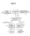
- FIG. 5 A system for transforming image signals which achieves the above-described series of transformation processing is shown schematically in Fig. 5.
- the input image data IND is sequentially read in the input image memory 2 via a low pass filter/interpolation circuit 1.
- the read image data is, in turn, read out by means of a read-out address signal RAD produced in a read-out address generator 3 and transmitted as an output image data OUD via an interpolation/low pass filter circuit 4.
- the read-out address generator 3 receives an output image address signal OADD generated by an output image address generator 5.
- the read-out address generator 3 receives a reference point signal (h o , v o ) obtained through an arithmetic operation, rotation transformation matrix data AR, B11, B21, B12, and B22 calculated on the basis of angle ⁇ in the rotation transform, and a value of radius r of the above-described cylindrical image CYL, these signals and data being derived from a control parameter calculation circuit 8 on the basis of data PPD representing a preset parameter inputted from a pointing device 6 and position assignment data PDD inputted from a joystick (control stick) 7.
- the read-out address generator 3 executes respective transform calculations for the four transformable parts of image OIG1, OIG2, OIG3, and OIG4 as described above with reference to Figs. 1(A) through 1(D) on the basis of the output image address signals OADD, reference point signal (h o , v o ), rotation transformation matrix data AR, B11, B21, B12, and B22, and radius r of the above-described cylindrical image CYL (in addition, a signal S-D to be described later) and read out the input image data which is to be the contents of image specified by the output image address fetched from the input image memory 2.
- the read-out address generator 3 has an internal circuit configuration shown in Fig. 6 and executes a sequential transform processing of each signal corresponding to the inverse transform steps shown in Fig. 4.
- both output image address signal OADD produced from the output image address generator 5 and reference point signal (h o , v o ) produced from the control parameter calculation circuit 8 are signals represented by addresses of respective picture elements on a raster screen (this is called real addresses).
- the read-out address signals RAD to be supplied from the read-out address generator 3 to the input image memory 2 need to be converted to data having the contents of the real addresses.
- the reference point (x o , y o ) on the basis of the above-described definition can correspond to the real address (h o , v o ).
- Such a conversion from the x, y coordinates and X, Y coordinates to corresponding real addresses (h, v) and (H, V) is executed simultaneously when the read-out address generator 3 executes the rotation transform.
- the read-out address generator 3 as shown in Fig. 6, the signal (H, V) indicative of the real address supplied from the output image address generator 5 as the output image address signal OADD is supplied to adders 16, 17 of a parallel translation (shift) circuit 15.
- the adders 16, 17 receive respective reference point signals (h o , v o ) supplied from the control parameter calculation circuit 8 as subtraction inputs so as to produce the addition outputs (H-h o ) and (V-v o ) representing the parallel translation processing such that the reference point (h o , v o ) is shifted to an origin.
- the addition outputs (H-h o ) and (V-v o ) are sent to a multiplier 19 in the rotation transform circuit 18.
- the reference point signal (h o , v o ) is derived from the control parameter calculation circuit 8 on the basis of the change in the output PDD of the joystick 7 and the position of the reference point (h o , v o ) is changed by an operation of joystick 7 so that the visual effect of the page being folded gradually can be achieved.
- the multiplier 19 multiplies the transformed data AR by the address signals H-h o and V-v o .
- the transformed data AR is derived from the control parameter calculation circuit 8 and the value of R*( ⁇ ) in the above-described equation (20) is obtained in the control parameter calculation circuit 8 as data having the contents expressed in the following equation multiplied by conversion coefficients in the equations (34) through (37).
- the data of angle ⁇ for rotation transform is previously inputted to the control parameter calculation circuit 8 using the pointing device 6.
- the control parameter calculation circuit 8 outputs the rotation transform data AR calculated from the equation (40).
- the output data RV01 appearing on an output terminal of the multiplier 19 is thus expressed by the following equation.
- the rotation transform data AR includes a conversion coefficient for converting the address (h, v) and (H, V) to square lattice coordinates (x, y) and (X, Y) (as shown in the above equation (40))
- the contents of output data RV01 are converted into the x, y coordinates and X, Y coordinates described with reference to the equations (18) through (33), on the basis of which the inverse transform arithmetic operation is executed at the subsequent stage of non-linear compression inverse transform circuit 20.
- the non-linear compression inverse transform circuit 20 calculates the non-linear compression inverse transform using the data of radius r sent from the control parameter calculation circuit 8. Specifically, an inverse transform calculation circuit 21 constituting the non-linear compression inverse transform circuit 20 calculates data x2 of the outputs RV01 produced from the previous stage of rotation transform circuit 18 in the axial direction of x2 and the calculation result is sent to a selection switching circuit 22.
- the selection switching circuit 22 receives directly the data x2 and enables the output of data on the part of image not requiring this inverse transform without passage through the non-linear compression inverse transform calculation circuit 21 when the data on the part of image not requiring such a transform is received.
- the selection switching circuit 22 receives as selective switching control signals CH x2 axis direction data x2 and a transform region specification signal SD (corresponds to the region D in Fig. 2) indicating that data on the regions of the parts of transformed image OIG3 and OIG4 requiring the inverse transform of non-linear compressions have reached from the circuit 8.
- the selection switching circuit 22 selects the output of the non-linear compression inverse transform calculation circuit 21 and outputs it as the output data x1 of the non-linear compression inverse transform circuit 20 upon arrival of the data corresponding to the parts of transformed image OIG3 and OIG4 and outputs the data x2 directly as the data x1 constituting the output NCOMP of the non-linear compression inverse transform circuit 20 upon arrival of the picture element data of the other parts of transformed image OIG1 and OIG2.
- a y-axis component y2 of the output RV01 from the multiplier 19 is directly outputted as the y-axis data y1 of the output NCOMP.
- the non-linear compression inverse transform circuit 21 calculates the above equations (25) and (26) by means of the following equation. After the calculation is executed, a minus sign attached to the term of operator F ⁇ 1 as a minus exponent is operated arithmetically at the subsequent stage of rotation transform circuit 23 in order to simplify the construction.
- the rotation transform circuit 23 executes the arithmetic operation of the equations (30) through (33) and the conversion of data represented by the square lattice coordinates (x1, y1) to the real address data (h, v).
- the terms cos ⁇ and -sin ⁇ are provided for the axial direction of x, as appreciated from the equation (4).
- the inverse transform operator F ⁇ 1 and minus sign in the coefficient 1 are used as shown in the equations (26) and (29).
- the x-axis component x1 among the outputs NCOMP of the non-linear compression inverse transform circuit 20 is sent to multipliers 25, 26 in which the rotation transform data B11 and B21 expressed in the following equations are multiplied by the component x1.
- the multiplied output of the multiplier 25 is directly sent to an adder 27 and is sent to an adder 29 via a sign inverter 28.
- the multiplied output of the multiplier 26 is directly sent to an adder 30 and sent to an adder 30 via a sign inverter 31.
- the y-axis component y1 among the non-linear compression inverse transformed outputs NCOMP is sent to the multipliers 35, 36 in which the rotation transform data B12, B22 expressed in the following equations are multiplied by the y-axis component y1.
- the adders 27, 30 directly receive the results of multiplication from the multipliers 25, 26 respectively in which the x-axis component x1 among the non-linear compression inverse transform outputs NCOMP is multiplied by the rotation transform data B11, B12.
- the adders 29, 32 receive the results of multiplication from the multipliers 25, 26 via the sign inverters 28, 31. Consequently, the result of calculations from the equations (44) and (46) are sent to the adders 27, 30 and the result of calculations from the equations (43) and (45) is sent to the adders 29, 32, respectively.
- This arithmetic operation means that the reference point (h o , v o ) is returned to the original position.
- output terminals of adders 43, 44 in the parallel translation (shift) circuit 40 appear addresses v a , v b in the y-axis direction for the parts of image at the front and rear sides of the transformed image PIG among the original image OIG (refer to Fig. 1(A)).
- These address signals h a , h b , v a , and v b are sent as the address data (h, v) of the read-out address signal RAD, with the higher priority taken to the address data corresponding to the rear side parts of image, i.e., OIG1, OIG3 than the front side parts of image, i.e., OIG2, OIG4 as appreciated from Fig. 1(D).
- the read-out address generator 3 in a case when the generator 3 carries out an image transformation such that the input image can be transformed to the output image having the page turn-over effect, the read-out address generator 3 is so constructed as to generate sequentially the transformed output image address and to execute an arithmetic operation of the inverse transform of the sequentially generated output image address into the read-out address signal RAD so that the part of image data required for the appearance of page turn-over effect among the image data stored in the input image data can assuredly be read out.
- Parameters representing a locus for a page to be turned over is preset in the control parameter calculation circuit 8 (refer to Fig. 5) using the pointing device 6.
- the data on the reference point (h o , v o ), rotation transform data AR, B11, B21, B12, and B22 calculated on the basis of angle ⁇ for the rotation transform, and data on the radius of the cylindrical image CYL, these data being generated on the basis of the preset parameters are modified by means of the joystick 7. Consequently, the reference point (h o , v o ), angle ⁇ of the rotation transform, and radius r of the above-described cylindrical image CYL can be changed in accordance with the positions specified by the joystick 7. Therefore, the output image data generating the page turn-over effect as if a series of changes from the beginning of page turn-over to the end of page turn-over were viewed perspectively from an upper position of the screen can be read out from the input image memory 2.
- the transformation of image signals with the page turn-over effect to be arithmetically operated as a three-dimensional surface can easily be achieved by the two-dimensional (plane) data transform and by one-dimensional compression transform of the part of output image constituting the surface part of the output image. Consequently, the effect of page turning over can easily be achieved with a simple construction.
Abstract
Description
- The present invention relates generally to a method and system for effecting a transformation of a video image from an original image on a TV screen applicable to for ex. a system for producing a special visual effect on a television screen in a television broadcasting station (e.g. GB-A-2119594).
- Such a kind of special visual effect system has been proposed in which image signals in a standard television method constructed so as to form a piece of two-dimensional image having a rectangular shape are converted into digital signals. Thereafter the digital image signals are read in predetermined address locations generated within an input image memory having a memory capacity corresponding to one field. When the output image data are read out by accessing the input image memory to read out the read-in data in an order changed from the read in order according to the necessity to display the output image data on the screen of a display unit, a piece of image having a special effect such that an image derived from input image data is geometrically changed can be displayed.
- In this case, a read-out address signal for the input image memory is generated by means of a read-out address transform circuit for transforming the input image address of the input image data according to the necessity.
- As the read-out address transform circuit, a circuit is used in which with a three-dimensional surface data previously stored on the basis of a concept such that on the basis of input image data generating a plane image, the input image data are converted into a three-dimensional surface and a calculation to map the input image on the three-dimensional surface using the three-dimensional surface data is achieved by software calculating means.
- However, there are problems in the conventional read-out address transform circuit. That is to say, a large scale of memory is not only required as a storage means for storing the three dimensional surface data but also the transform calculation for many picture elements constituting the displayed image need to be executed so that a large-sized and complicated construction of the whole special effect system cannot be avoided.
- Especially, in a case when the whole screen on which the input video image is displayed is transformed into a video screen which can be viewed as if the screen were three-dimensionally inflexed, the inflexed surface being varied with time, an oversized construction of the special visual effect system exceeding a practical capacity range connot be avoided. Therefore, it is desirable to provide a method and system for effecting a transformation of the video image which achieves a practically sufficient special visual effect described with a simple hardware construction in place of various conventional software methods.
- With these problems in mind, it is an object of the present invention to provide a system and method for effecting a transformation of a video image on a video screen which can remarkably reduce a scale of the special effect system as compared with the above-described system and in which a plane image formed with the input image data is converted into an image signal having an effect such that an image on the screen can be viewed as if a page of a book were turned over. This is referred to as a page turn-over effect.
- This effect can be achieved by a method for effecting a transformation of a video image on a video screen, which comprises the steps of: (a) storing an input video image in a memory device; (b) defining a two-dimensional address plane in a memory area of the memory device; (c) providing a first line on the address plane to divide the address plane into first and second regions; (d) providing second and third lines on the first and second regions of the address plane in parallel to the first line; (e) calculating address data of the address plane for providing transferred address data so that the address data of the first region are symmetrically transformed with respect to the first line, and the address data between the first and second lines and between the first and third lines are non-linear compression transformed along an axis perpendicular to the first line; (f) calculating transformed address data between the first and second lines and between the first and third lines when address data between the first and second lines and between the first and third lines are non-linear compression transformed along an axis perpendicular to the first line; and (g) reading out the input video image from the memory device data and generating an output video image according to the transformed address data, whereby the output image can be viewed such as to be turned over along the first line.
- This can be achieved by a system for effecting a transformation of a video image on a video screen, which comprises (a) first means for storing input image data, (b) second means for sequentially generating a positional output image address signal, (c) third means for presetting parameters representing a locus on which an output of the video image is turned over as if a sheet of paper were folded up, (d) fourth means for sequentially generating position designation signals indicative of a displacement of the input image on a two-dimensional plane, (e) fifth means for calculating values including a positional reference point signal of the input image on the two-dimensional plane on the basis of which the input image is displaced, rotation transform matrix data based on a given angle through which the two-dimensional plane is rotated, and a radius data on a virtual cylindrical image on which part of the input image is wound, the positional reference point signal, the rotation transform matrix data, radius data being based on preset parameters drived from the third means and position designation signals derived from the fourth means, (f) sixth means for executing transform arithmetic operations for transformable parts of an output video image, the transformable parts being defined by a first part representing a rear part of the output video image which is wound on an upper surface of the cylindrical image as viewed through the video screen, a second part representing a front part of the output video image which is outside of a projection portion of the cylindrical image, a third part representing the front part of the output video image which is wound on a lower surface of the cylindrical image as viewed through the video screen, and a fourth part representing the rear part of the output image which is outside of the wound first part so as to overlap on the second part, on the basis of the reference point signal, rotation transform matrix data, and radius data of the cylindrical image calculated by the fifth means and reading out the input image data the contents of which are to be the output image and specified by the positional output image address signal generated by the second means, and (g) seventh means for displaying the input video image whose data are stored in the first means and read out from the first means by the sixth means according to the positional output image address signal on the video screen so that the whole video screen can be viewed as if a sheet of paper were being folded up.
- This can also be achieved by a method for effecting a transformation of a video image on a video screen, comprises the steps of:
- (a) defining a two-dimensional address plane within a memory area;
- (b) storing an input video image within the memory area so that data on each picture element thereof is placed at the corresponding address;
- (c) virtually placing a cylinder-shaped image whose radius of a section thereof is varied on the address plane defined in the step (a) and winding a part of the address plane on the cylinder shaped image;
- (d) displacing the cylinder shaped image along a predetermined direction on the address plane with its radius varied with time so that the address plane is turned over along the predetermined direction;
- (e) performing parallel translation and rotation for the whole address plane, a non-linear compression with respect to the predetermined direction for front and rear parts of the address plane which are wound on a surface of the cylinder shaped image as viewed vertically through the video screen, and a fold back of the rear part of the address plane;
- (f) inverse transforming the transformed address data obtained in the step (e) so as to unfold the output video image and reading out inverse transformed image address data with a priority taken for the turned over part of output image as input image address data and
- (g) displaying the input image on the video screen on the basis of the input image address, whereby the video image on the video screen can be viewed as if a page were turned over.
-
- A more complete understanding of the present invention may be obtained from the following description taken in conjunction with the attached drawings and in which like reference numerals designate corresponding elements and in which:
- Figs. 1(A) through 1(D) are schematic diagrams of image transformation procedure in the method for transforming image signals according to the present invention;
- Fig. 2 is a schematic diagram of an unfolded transformed image;
- Fig. 3 is a schematic diagram for explaining the compression transform processing;
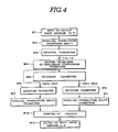
- Fig. 4 is a flowchart of image signal transform processing method according to the present invention;
- Fig. 5 is a circuit block diagram of the system for transforming image signals according to the present invention;
- Fig. 6 is a schematic circuit block diagram of a read-
out address generator 3 shown in Fig. 5; and - Figs. 7 and 8 are schematic diagrams for explaining a model of the image signal transform method according to the present invention.
- Reference will hereinafter be made to the drawings in order to facilitate an understanding of the present invention.
- In a method for effecting a transformation of a video image according to the present invention, a positional relationship of each picture element on a video screen between input picture image data and output image data is modeled on the basis of a technique shown in Fig. 7 and Fig. 8.
- Suppose that a virtual cylindrical image CYL is mounted on an input image IM represented by input image data so as to cross the input image IM obliquely. In addition, one end IM1 of the input image IM is folded and wound around the cylindrical image CYL. A screen in a state in which the end IM1 described above is wound around the cylindrical image CYL is viewed from an upward position in a vertical direction with respect to an unwound part of the screen IMO. A construction of the screen in this case can provide a visual effect such that an image represented by a piece of paper can be visualized as if it were gradually turned over.
- In more detail simultaneously when a center axis of the cylindrical image CYL is translated in parallel to a direction in which one page of a book is turned, a diameter of the cylindrical image CYL is increased according to an increase in distance of the parallel translation of the cylindrical image CYL.
- One sheet of image is thus turned over obliquely from one of the corners. As the turned sheet part of image becomes large as compared with the remaining sheet part, a diameter of a part of image IM2 currently wound on the cylindrical image CYL continued from the folded part of image IM1 becomes gradually varied and the position of the cylindrical image CYL is accordingly moved in a page turned over direction denoted by an arrow MK1.
- As shown in Fig. 7, suppose that with the part of the image IM wound on the cylindrical image CYL, the contents of the whole image on the screen when viewing the screen on which the part of image is wound on the cylindrical image from a position vertical to a plane of the part of image IM. In this case, the unfolded part of image IG0 remains unchanged without image alteration by a compression, shift, and rotation. On the other hand, a part of the image IG1 folded back over the part of image IG0 indicates inversely projected contents of, e.g., part of image IG0. In addition, a part of image IG21 located below the part of image IM2 (refer to Fig. 7) wound on the cylindrical image CYL has projected contents of the image before the part of image IMO is wound on the cylindrical image CYL without folding back of image and which is subjected to a non-linear compression. In addition, the upper part of image IG22 has projected contents with the folding back of the previous image IG0 before winding on the image CYL and with a non-linear compression in image.
- When the effect of page turning over is modeled as shown in Fig. 8, the contents of the part of image IG2 wound on the cylindrical image CYL can be achieved if the contents of the image before the folding back of the original image is processed by way of a one dimensional non-linear compression only for a direction (represented by an arrow mark MK2) orthogonal to a fold line L1 on a plane including the part of image IG0 with respect to the fold line L1, i.e., a straight line parallel to a center axis of the cylindrical image CYL. For the transform processing when each picture element constituting the image on the screen is mapped on the part of the wound part of image IG2, the non-linear compression transform may be executed only for one axial direction, i.e., the direction MK2 orthogonal to the fold line L1.
- The one-axis direction non-linear compression transform processing may be executed over the confines from the fold line L1 through first and second non-linear compression parts of images IG21 and IG22 to a fold boundary line L2 representing a boundary between the original part of image IG0 and folded part of the image IG1. The folded boundary line L2 corresponds to a position of the wound part of image IM2 in Fig. 7 which has been separated from the cylindrical image CYL and comprising upper and lower fold boundary lines L21, L22.
- In order to effect a transformation of the folded part of image into an image projected on a plane including the original part of image IG0 in Fig. 8, the position of each picture element on the original screen may sequentially be transformed in accordance with a procedure of transformation processing in Figs. 1(A) through 1(D).
- In a first transformation step, the fold line L1 is set on an original part of image OIG on a x-y plane in an orthogonal coordinate system.
- In a second transformation step, the original part of image OIG is translated in parallel to an x₁ axis direction by a distance +α so that the set fold line L1 is aligned with a y₁ axis and is rotated through +ϑ in a counterclockwise direction, as shown in Figs. 1(A) and 1(B).
- Thereafter, a part of image OIGN which belongs to a negative area in the x₁ axis direction (-x₁, y₁)(-x₁, -y₁) is folded up along the y₁ axis (hence, the fold line L1) to overlap the part of image OIGN over the remaining part of image OIGP present in a positive area of the x₁ axis direction (x₁, y₁)(x₁, -y₁).
- Consequently, although the unfolded part of image OIGP is maintained as the original image OIG without being subjected to the transformation processing, the part of image OIGN is transformed to take a reversed form of the original image OIG (denoted by oblique lines). The whole image executed under such a folding transformation processing is represented on the x₁ y₁ plane.
- Next, in a third transformation step, a fold boundary line L2 is set which is parallel to the fold line L1 on the part of image OIGN and the part of image OIGP mutually overlapping and then a part of area ER (refer to Fig. 1(c)) between the parts of images OIGN and OIGP is non-linearly compressed. The non-linear compression is carried out in such a way that the part of the image wound on the cylindrical image CYL obtained through a perspective view from an upward direction as described above with reference to Fig. 8 is produced on the x₂, y₂ plane. This can be achieved by obtaining the position of each picture element on the cylindrical image calculated as a result of mapping the parts of plane images OIGN and OIGP present in the area ER on a surface of the cylindrical image extending toward a direction along the y₂ axis.
- Consequently, the upper section of the part of image OIGN which belongs to the area ER is transformed into a part of image OIG3 representing the cylindrical surface through the non-linear compression processing with respect to the one axis of the x₂ axis direction.
- A plane lower part of image OIGP which belongs to the area ER is transformed into the part of image OIG4 (refer to Fig. 1(c)) representing the cylindrical surface through the non-linear compression processing with respect to the x₂ axis. It should be noted that the parts OIG1, OIG2 other than the area ER which belong to the parts of images OIGN, OIGP shown in Fig. 1(C) are not subjected to the non-linear compression transformation.
- Next, in a fourth transformation step, the whole transformed image obtained as shown in Fig. 1(C) is rotated by +ϑ in the clockwise direction and translated in parallel (shifted) to the x₂ direction by -α as appreciated from Fig. 1(D).
- The above-described parallel translation and rotation transformations means such steps as to return the position of the whole image moved by the parallel translation and rotation transformation executed as shown in Fig. 1(A) to the original image position.
- In this way, all transformation operations are ended and the entire image on the screen PIG after the transformation operation represented on the X Y plane provides the same visual effect as the perspective view from the upward direction orthogonal to a plane including the original screen OIG when a part of the left upward corner QL in the original screen OIG (Fig. 1(A)) is folded up in a direction orthogonal to the fold line L1.
- If the transformed image PIG shown in Fig. 1(D) is unfolded on a plane as shown in Fig. 2, the part of transformed image OIG4 appears on the screen from the folded line L1 to the lower fold boundary line L22 which has been subjected to the non-linear compression and the part of transformed image OIG3 is also present between the fold line L1, an upper fold boundary line L21 drawn along a position which is axially symmetric to the lower fold boundary line L22 with respect to the fold line L1, and the upper part of image OIG1 which has not been subjected to the non-linear compression transformation is present outside of the upper fold boundary line L21.
- On the other hand, if the partially transformed image PIG shown in Fig. 2 is compared with the original image OIG shown in Fig. 1(A), the part of transformed image OIG2 which has not been subjected to the non-linear compression transformation is subjected to such a transformation that a corresponding part of the original image OIG on the x-y plane is translated in parallel by the distance +α along the x axis (Fig. 1(A)), is then rotated by the angle +ϑ in the counterclockwise direction (Fig. 1(B)), and is, in turn, rotated in the clockwise direction and translated in parallel to the x axis direction by -α (Fig. 1(D)). However, during such a transformation procedure, the position of each picture element in the part of image OIG2 is finally returned to the original position of the corresponding picture element (pixcel) in the original image OIG. Consequently, the part of transformed image OIG2 is directly derived from the corresponding part of the original image OIG without any alternation. Thus, a position (X, Y) of each picture element on the X, Y plane in an area of the transformed part of image OIG2 can be expressed in the following equation by transforming a position (x, y) in the corresponding part of image present on the x, y plane.

- Next, the part of transformed image OIG4 is obtained by parallel translating the corresponding part of transformed image OIG by +α (Fig. 1(A)), rotating that part through the angle +ϑ in the counterclockwise direction (Fig. 1(B)), transforming that part in the non-linear compression (Fig. 1(C)). and rotating that part through the angle +ϑ in the clockwise direction and translating that part in parallel by the distance -α. In this case, if a position of each picture element (x, y) present on the part of original image OIG corresponding to the part of transformed image OIG4 is expressed relatively to a reference position (xo, yo), a position (X, Y) on the transformed image PIG of each picture element can be expressed in the following equation.

- In the above equation (2), a first term of the right side represents an amount of the parallel translation of the part of image with respect to the screen after processing of the non-linear compression transformation and R*(ϑ) denotes a rotation matrix in which the image on the screen is rotated through +ϑ in the counterclockwise direction. The rotation matrix R*(ϑ) may be expressed as

- In addition, R*(-ϑ) denotes the coordinate position after the processing of the non-linear compression transformation is rotated through -ϑ in the counterclockwise direction and may be expressed as follows:

- Furthermore, the second matrix in the equation (2) may be expressed as follows.

- In the equation (5), the right side denotes the execution of the non-linear compression transformation. In the equation (5), F denotes an operator for obtaining a value in the X ordinate after transformation as expressed below:

In the equation (6), r denotes a radius of the cylindrical image CYL (refer to Figs. 1(A) through 1(D)) used for the non-linear compression transformation and is expressed by the following equation:
- Furthermore, the fourth matrix of the right-side second term of the above equation (2), i.e.,

indicates that the position of each picture element (x, y) before the transformation processing is translated in parallel by the distance corresponding to the coordinates (xo, yo) of the reference position. Consequently, the reference position (xo, yo) is placed on a position which coincides with an origin of x₁ y₁ plane (Fig. 1(B)) after transformation. - Next, the part of transformed image OIG3 is derived from the following procedure: the corresponding part of the original part of image OIG is translated in parallel by +α (refer to Fig. 1(A)), rotated through the angle +ϑ in the counterclockwise direction and folded back (refer to Fig. 1(B)), transformed through the non-linear compression (refer to Fig. 1(C)), and finally rotated through the angle +ϑ in the clockwise direction together with the parallel translation by -α (refer to Fig. 1(D)).
- In this case, the part of transformed image OIG3 is derived in the similar transformation procedure as the other part of transformed image OIG4 except the above-described fold back transformation procedure. The part of transformed image OIG3 can be expressed in the following equation.

- It should be noted that a difference between the equations (2) and (9) lies in a term -F which is included in the second matrix of the second term of the equation (9). The minus sign of the term F represents the original image being turned over.
- Next, the part of transformed image OIG1 is derived from the following procedure: after parallel translation by +α, the original image thereof is subjected to the rotation transformation through the angle +ϑ in the counterclockwise direction and is folded (refer to Fig. 1(B)), and thereafter undergoes the rotation transformation through +ϑ in the clockwise direction and parallel translation by -α. Consequently, each picture element in the part of transformed image OIG1 is transformed into a position with respect to the original image OIG which can be expressed in the following equation.

- A difference of the above equation (11) from the equation (9) lies in the use of a coefficient -1 in place of the operator -F in the second matrix of the right-side second term. This represents that in the case of equation (11) the image before subjection of transformation is turned over through the fold back transformation processing without the non-linear compression transformation.
- In this way, the parts of transformed image OIG2, OIG4, OIG3, and OIG1 constituting the transformed picture PIG can be obtained by transforming the image on the original part OIG into such positions as to satisfy the transformation equations represented by equations (1), (2), (9), and (11).
- The equation (1) represents that the part of transformed image OIG2 is returned to the same position as the original part of image OIG as the result of a series of transformation steps. In this case, the following equation can be substituted for the equation (1) if the intermediate series of transformation processings are included.

The transformation equations applied to all of the parts of image OIG2, OIG4, OIG3, and OIG1 can be represented in the following general formula.
In the above equation (13), T* denotes a matrix in which the operator F or a numerical valve substituted for the operator F is included for each arithmetic operation. - The non-linear compression transformation equation represented by the equation (6) can be obtained by the utilization of the relationship shown in Fig. 3.
- In details, in the case when the double folded transformed image on the x₁, y₁ plane shown in Fig. 1(B) is subjected to the non-linear compression as shown in Fig. 1(C), the continuous parts OIG4, OIG3 of the image following the part of the transformed image OIG2 are folded back so as to be wound about the cylindrical image having a radius r.
- In this case, supposing that when the part of transformed image OIG4 present between the fold line L1 on the x₁ axis and the folded boundary line L22 (having a width of D) is wound about an angular range of


- In the above equation (14), the width D can be expressed as follows since the part of transformed image OIG4 having the width D is wound on the angular range of π/2 at a quarter lower part of an outer surface of the cylindrical image CYL.

- In addition, the following equation is established from the relationship between the angle ∅ for the transformed point of the ordinate x₁ and wound angle π/2 with respect to a center of the cylindrical image CYL.

If the equations (15) and (16) are substituted for the above equation (14), the following relationship is established.
- Although the transformation from the x₁, y₁ plane to the x₂, y₂ plane is described with reference to Fig. 3, the general formula can be expressed as the above-mentioned equation (6).
- In order to display the transformed image obtained in the fourth transformation step (Fig. 1(D)) in accordance with the transformation procedure of Figs. 1(A) through 1(D) as the output image on the screen, the data on the original image OIG (refer to Fig. 1(A)) is sequentially written into an input image memory together with a predetermined address data (, i.e., input image address data). If an output image address is inversely transformed into the input image address in order to sequentially access the input image address corresponding to the output image address required for the display of the output image after transformation of the input image, the transformed output image (refer to Fig. 1(D)) can be read out from the input image memory. To obtain the corresponding input image address from the output image address, in this way, image position data on which the transformation processing has been executed in the order beginning from Fig. 1(A) and ending to Fig. 1(D) is inversely transformed in the procedure starting from Fig. 1(D) and ending to Fig. 1(A) on the basis of the output image address.
- The above-described inverse transformation can be derived by solving the general formula expressed in the equation (13) with respect to the term expressed below

Then the following equation is established.
Each value of picture element expressed in the above equation (19) may be obtained sequentially from the coordinates (X, Y) of the transformed image PIG as the coordinate (x, y) of the original image OIG. - The above-described inverse transformation is executed in accordance with a processing sequence shown in Fig. 4.
- In a step SP1 of Fig. 4, a position (X, Y) of transformed image PIG (hence, output image address) is inputted.
- In the next steps SP2 and SP3, the parallel translation (shift) transformation and rotation transformation are executed on the basis of the following equation (20).

- The coordinate position (x₂, y₂) on the x₂, y₂ plane shown in Fig. 1(C) is thus obtained.
- In an image on the x₂, y₂ plane, the above-described fold line L1 is represented by the following equation.

- On the other hand, the above-described fold boundary line L2 (hence, corresponding to a center axial line of the cylindrical image about which the part of transformed image is wound) is expressed by the following equation.

- In addition, in the transformed image of the x₂, y₂ plane, any input image is not present in a negative area outside the fold line L1 and an inverse transform of the non-linear compression is necessary for an area between the fold line L1 and fold boundary line L2.
- Next, in a step SP4 of Fig. 4 the inverse transform of the non-linear compression transformed image on the x₂, y₂ plane is executed so as to form the transformed image on the x₁, y₂ plane as described above with reference to Fig. 1(B).
- Thereafter, in a step SP5, a fold back transform processing is executed so as to unfold the folded image.
- Since in the transformation processing in the steps SP4 and SP5, there is no part of an image to be transformed in the following range on the x₂, y₂ plane, no transformation is executed.

- On the other hand, since in the area expressed below on the x₂, y₂ plane the two parts of image OIG3 and OIG4 are mutually overlapped, the inverse transform needs to be executed for each part of image.

- For a point (x₂, y₂) of the part of image OIG4 in which the image is not turned over, a point (x₁₄, y₁₄) obtained on the x₁, y₁ plane through the transformation is expressed as follows.

- For a point (x₂, y₂) within the part OIG3 in which the image is turned over, a point (x₁₃, y₁₃) obtained on the x₁, y₁ plane through the transformation is expressed as follows.

- In the equations (25) and (26), F⁻¹ denotes an operator for executing the inverse transform of the non-linear compression represented by F.
- In addition, for a point (x₂, y₂) within the part OIG2 in which the contents of image is not turned over, a point (x₁₂, y₁₂) obtained on the x₁, y₁ plane through the transformation is expressed as follows.

- The above-described equation (28) indicates that neither inverse non-linear compression transform nor fold back transform is executed as appreciated from the use of
coefficient 1 in place of the operator F⁻¹. - On the other hand, for a point (x₂, y₂) of the part OIG1 in which the contents of image is turned over, a point (x₁₁, y₁₁) obtained on the x₁, y₁ plane through the transformation is expressed as follows.

- The above-described equation (29) indicates that the contents is folded back as appreciated from the use of coefficient -1 in place of the operator F⁻¹.
- Whereas the fold-back transform outputs for the parts of image OIG1 and OIG3 are obtained in the step SP5 and are subjected to the rotation and parallel translation transforms in the next steps SP6 and SP7, for the other parts of image OIG2 and OIG4, they are directly subjected to the rotation and parallel translation transformations without the fold-back transform in the next steps SP8 and SP9, respectively. Such series of transforms are executed respectively for the points (x₁₁, y₁₁), (x₁₂, y₁₂), (x₁₃, y₁₃), (x₁₄, y₁₄) on the x₁, y₁ plane related to the parts of transformed image OIG1, OIG2, OIG3, and OIG4. Consequently, the points (xo1, yo1), (xo2, yo2), (xo3, yo3), (xo4, yo4) on the x, y plane (refer to Fig. 1(A)) are derived from the following four equations, respectively.

- In this way, whenever the output image address allocated to each picture element included in the parts of transformed images OIG1, OIG2, OIG3, and OIG4 is specified by a sequential specification of an output address allocated to each picture element of the transformed image PIG described above with reference to Fig. 1(D), the input image address allocated to a picture element located at a position expressed by the corresponding one of the above-described equations (30) through (33) can be fetched from the input image memory as the read-out address.
- Consequently, the image data constituting each part of the transformed image can be read out of the input image memory. It should be noted that it becomes practically necessary to select with a higher priority the image data on a part of transformed image which is located at an upper side of the mutually opposing parts of the transformed image, in a case when a plane image having a page turned-over effect as shown in Fig. 1(D) is produced.
- Therefore, a control of the priority for each part of image is carried out as shown in step SP10 of Fig. 4.
- The order of priority for the transformed image exhibiting the page turn-over effect in Fig. 1(D) is set in such a way that the part of image OIG1 has a higher priority than the part of image OIG2 and the part of image OIG3 has a higher priority than the part of image OIG4.
- Thus, in the same way as a page of a book is turned over, a lower part of the front page hidden by the folded up part of the rear page is not displayed so that the input image address (x, y) which is capable of forming such an image as having more practical page turn-over effect can be produced in the final step SP11.
- A system for transforming image signals which achieves the above-described series of transformation processing is shown schematically in Fig. 5.
- As shown in Fig. 5, the input image data IND is sequentially read in the
input image memory 2 via a low pass filter/interpolation circuit 1. The read image data is, in turn, read out by means of a read-out address signal RAD produced in a read-outaddress generator 3 and transmitted as an output image data OUD via an interpolation/lowpass filter circuit 4. - The read-out
address generator 3 receives an output image address signal OADD generated by an outputimage address generator 5. - Furthermore, the read-out
address generator 3 receives a reference point signal (ho, vo) obtained through an arithmetic operation, rotation transformation matrix data AR, B11, B21, B12, and B22 calculated on the basis of angle ϑ in the rotation transform, and a value of radius r of the above-described cylindrical image CYL, these signals and data being derived from a controlparameter calculation circuit 8 on the basis of data PPD representing a preset parameter inputted from apointing device 6 and position assignment data PDD inputted from a joystick (control stick) 7. - In addition, the read-out
address generator 3 executes respective transform calculations for the four transformable parts of image OIG1, OIG2, OIG3, and OIG4 as described above with reference to Figs. 1(A) through 1(D) on the basis of the output image address signals OADD, reference point signal (ho, vo), rotation transformation matrix data AR, B11, B21, B12, and B22, and radius r of the above-described cylindrical image CYL (in addition, a signal S-D to be described later) and read out the input image data which is to be the contents of image specified by the output image address fetched from theinput image memory 2. - In addition, the read-out
address generator 3 has an internal circuit configuration shown in Fig. 6 and executes a sequential transform processing of each signal corresponding to the inverse transform steps shown in Fig. 4. - Although in the image transform processing described above with reference to Figs. 1(A) through 1(D) the arithmetic operation is carried out on the basis of square lattice coordinates between x, y plane and X, Y plane, both output image address signal OADD produced from the output
image address generator 5 and reference point signal (ho, vo) produced from the controlparameter calculation circuit 8 are signals represented by addresses of respective picture elements on a raster screen (this is called real addresses). The read-out address signals RAD to be supplied from the read-outaddress generator 3 to theinput image memory 2 need to be converted to data having the contents of the real addresses. - Therefore, a relationship between each point (x, y) and (X, Y) on the x, y coordinates and X, Y coordinates and each real address (h, v) and (H, V) corresponding to the former coordinate point is defined in the following four equations.

- The reference point (xo, yo) on the basis of the above-described definition can correspond to the real address (ho, vo).

- Such a conversion from the x, y coordinates and X, Y coordinates to corresponding real addresses (h, v) and (H, V) is executed simultaneously when the read-out
address generator 3 executes the rotation transform. - The read-out
address generator 3, as shown in Fig. 6, the signal (H, V) indicative of the real address supplied from the outputimage address generator 5 as the output image address signal OADD is supplied toadders 16, 17 of a parallel translation (shift)circuit 15. - The
adders 16, 17 receive respective reference point signals (ho, vo) supplied from the controlparameter calculation circuit 8 as subtraction inputs so as to produce the addition outputs (H-ho) and (V-vo) representing the parallel translation processing such that the reference point (ho, vo) is shifted to an origin. The addition outputs (H-ho) and (V-vo) are sent to amultiplier 19 in therotation transform circuit 18. - It should be noted that the reference point signal (ho, vo) is derived from the control
parameter calculation circuit 8 on the basis of the change in the output PDD of thejoystick 7 and the position of the reference point (ho, vo) is changed by an operation ofjoystick 7 so that the visual effect of the page being folded gradually can be achieved. - The
multiplier 19 multiplies the transformed data AR by the address signals H-ho and V-vo. The transformed data AR is derived from the controlparameter calculation circuit 8 and the value of R*(ϑ) in the above-described equation (20) is obtained in the controlparameter calculation circuit 8 as data having the contents expressed in the following equation multiplied by conversion coefficients in the equations (34) through (37).
- The data of angle ϑ for rotation transform is previously inputted to the control
parameter calculation circuit 8 using thepointing device 6. The controlparameter calculation circuit 8 outputs the rotation transform data AR calculated from the equation (40). - The output data RV01 appearing on an output terminal of the
multiplier 19 is thus expressed by the following equation.
- Since the rotation transform data AR includes a conversion coefficient for converting the address (h, v) and (H, V) to square lattice coordinates (x, y) and (X, Y) (as shown in the above equation (40)), the contents of output data RV01 are converted into the x, y coordinates and X, Y coordinates described with reference to the equations (18) through (33), on the basis of which the inverse transform arithmetic operation is executed at the subsequent stage of non-linear compression
inverse transform circuit 20. - The non-linear compression
inverse transform circuit 20 calculates the non-linear compression inverse transform using the data of radius r sent from the controlparameter calculation circuit 8. Specifically, an inversetransform calculation circuit 21 constituting the non-linear compressioninverse transform circuit 20 calculates data x₂ of the outputs RV01 produced from the previous stage ofrotation transform circuit 18 in the axial direction of x₂ and the calculation result is sent to aselection switching circuit 22. Theselection switching circuit 22 receives directly the data x₂ and enables the output of data on the part of image not requiring this inverse transform without passage through the non-linear compression inversetransform calculation circuit 21 when the data on the part of image not requiring such a transform is received. - In addition, the
selection switching circuit 22 receives as selective switching control signals CH x₂ axis direction data x₂ and a transform region specification signal SD (corresponds to the region D in Fig. 2) indicating that data on the regions of the parts of transformed image OIG3 and OIG4 requiring the inverse transform of non-linear compressions have reached from thecircuit 8. - In this way, the
selection switching circuit 22 selects the output of the non-linear compression inversetransform calculation circuit 21 and outputs it as the output data x₁ of the non-linear compressioninverse transform circuit 20 upon arrival of the data corresponding to the parts of transformed image OIG3 and OIG4 and outputs the data x₂ directly as the data x₁ constituting the output NCOMP of the non-linear compressioninverse transform circuit 20 upon arrival of the picture element data of the other parts of transformed image OIG1 and OIG2. On the other hand, a y-axis component y₂ of the output RV01 from themultiplier 19 is directly outputted as the y-axis data y₁ of the output NCOMP. - The non-linear compression
inverse transform circuit 21 calculates the above equations (25) and (26) by means of the following equation.
After the calculation is executed, a minus sign attached to the term of operator F⁻¹ as a minus exponent is operated arithmetically at the subsequent stage ofrotation transform circuit 23 in order to simplify the construction. - The
rotation transform circuit 23 executes the arithmetic operation of the equations (30) through (33) and the conversion of data represented by the square lattice coordinates (x₁, y₁) to the real address data (h, v). In details, in the arithmetic operation of the term R*(-ϑ) in the above equations (30) through (33), the terms cos ϑ and -sin ϑ are provided for the axial direction of x, as appreciated from the equation (4). For the matrix of the right-side first term, the inverse transform operator F⁻¹ and minus sign in thecoefficient 1 are used as shown in the equations (26) and (29). - Therefore, the inverse transform operator in the non-linear compression inverse transform matrix and sign in the term of the coefficient are moved to the term of x in the rotation matrix. Thereafter, when the arithmetic operation of the rotation transform matrix is executed as shown in the following four equations (43) through (46), the sign in the term x is exchanged so that the arithmetic operation for all parts of transformed image can be executed using the same construction shown in Fig. 6.


- Therefore, the x-axis component x₁ among the outputs NCOMP of the non-linear compression
inverse transform circuit 20 is sent tomultipliers 
- The multiplied output of the
multiplier 25 is directly sent to anadder 27 and is sent to anadder 29 via asign inverter 28. The multiplied output of themultiplier 26 is directly sent to anadder 30 and sent to anadder 30 via asign inverter 31. - On the other hand, the y-axis component y₁ among the non-linear compression inverse transformed outputs NCOMP is sent to the
multipliers 
- Thereafter, the multiplied output of the
multiplier 35 is sent to theadders multiplier 36 is sent to theadders - The
adders multipliers adders multipliers sign inverters adders adders - In this way, the results of arithmetic operations RV02 using the above-described equations (43) through (46) are sent to the
rotation transform circuit 23, the reference point data ho, ho, vo, vo are respectively added to theadders 41, 42, 43, 44 constituting the parallel translation (shift)circuit 40. - This arithmetic operation means that the reference point (ho, vo) is returned to the original position.
- Consequently, among the parts of original image OIG (refer to Fig. 1(A)), the addresses ha, hv in the direction of x axis of the parts of image OIG1, OIG3, OIG2, and OIG4 corresponding to the rear and front portions of the transformed image PIG can be obtained.
- On the other hand, output terminals of adders 43, 44 in the parallel translation (shift)
circuit 40 appear addresses va, vb in the y-axis direction for the parts of image at the front and rear sides of the transformed image PIG among the original image OIG (refer to Fig. 1(A)). - These address signals ha, hb, va, and vb are sent as the address data (h, v) of the read-out address signal RAD, with the higher priority taken to the address data corresponding to the rear side parts of image, i.e., OIG1, OIG3 than the front side parts of image, i.e., OIG2, OIG4 as appreciated from Fig. 1(D).
- According to the internal configuration of the read-out
address generator 3 shown in Fig. 6, in a case when thegenerator 3 carries out an image transformation such that the input image can be transformed to the output image having the page turn-over effect, the read-outaddress generator 3 is so constructed as to generate sequentially the transformed output image address and to execute an arithmetic operation of the inverse transform of the sequentially generated output image address into the read-out address signal RAD so that the part of image data required for the appearance of page turn-over effect among the image data stored in the input image data can assuredly be read out. - Parameters representing a locus for a page to be turned over is preset in the control parameter calculation circuit 8 (refer to Fig. 5) using the
pointing device 6. In addition, the data on the reference point (ho, vo), rotation transform data AR, B11, B21, B12, and B22 calculated on the basis of angle ϑ for the rotation transform, and data on the radius of the cylindrical image CYL, these data being generated on the basis of the preset parameters, are modified by means of thejoystick 7. Consequently, the reference point (ho, vo), angle ϑ of the rotation transform, and radius r of the above-described cylindrical image CYL can be changed in accordance with the positions specified by thejoystick 7. Therefore, the output image data generating the page turn-over effect as if a series of changes from the beginning of page turn-over to the end of page turn-over were viewed perspectively from an upper position of the screen can be read out from theinput image memory 2. - As appreciated from Figs. 5 and 6,a major part of all arithmetic operations is achievable by the hardware construction so that the image signal transform system which can remarkably simplify part of a software arithmetic operation program as compared with the software execution for all arithmetic operations.
- According to the present invention, the transformation of image signals with the page turn-over effect to be arithmetically operated as a three-dimensional surface can easily be achieved by the two-dimensional (plane) data transform and by one-dimensional compression transform of the part of output image constituting the surface part of the output image. Consequently, the effect of page turning over can easily be achieved with a simple construction.
- It will be clearly understood by those skilled in the art that the foregoing description is made in terms of preferred embodiment and various changes and modifications may be made without departing from the scope of the invention which is to be defined by the appended claims.
Claims (21)
- A method for effecting a transformation of a video image on a video screen, comprising the steps of:a) storing an input video image (OIG, IM) in a memory device;b) defining a two-dimensional address plane in a memory area of said memory device;c) providing a first line (L1) on said address plane to divide said address plane into first and second regions;d) providing second and third lines (L21, L22) on said first and second regions of said address plane;e) calculating address data of said address plane for providing transferred address data so that said address data of said first region are symmetrically transformed with respect to said first line;f) calculating said address data between said first and second lines and between said first and third lines so that said address data between said first and second lines and between said first and third lines are non-linear compression transformed along an axis perpendicular to said first line; andg) reading out said input video image from said memory device and generating an output video image according to said calculated address data, whereby said output image can be viewed such as to be turned over along said first line.
- The method according to claim 1, wherein said method further comprises the steps ofh) transforming parallel translation and rotation for said address plane so that said first line coincides with one axis of said address plane before said transforming of the parallel translation and rotation is carried out; andi) transforming inverse parallel translation and rotation for said address plane so that axes of said address plane are returned to original condition.
- A system for effecting a transformation of a video image on a video screen, comprising;a) first means (2) for storing input image data (IM);b) second means (5) for sequentially generating a positional output image address signal;c) third means (6) for presetting parameters representing a locus on which an output of the video image is turned over as if a sheet of paper were folded up;d) fourth means (7) for sequentially generating position designation signals indicative of a displacement of the input image on a two-dimensional plane;e) fifth means (8) for calculating values including a positional reference point signal of the input image (IM) on the two-dimensional plane on the basis of which the input image is displaced, rotation transform matrix data based on a given angle (ϑ) through which the two-dimensional plane is rotated, and a radius data (r) on a virtual geometrical image (CYL) on which part of the input image is wound, said positional reference point signal, rotation transform matrix data, and radius data being based on preset parameters derived from said third means (6) and position designation signals derived from said fourth means (7);f) sixth means (3) for executing transform arithmetic operations for transformable parts of an output video image, said transformable parts being defined by a first part representing a rear part of the output video image which is wound on an upper surface of said geometrical image (CYL) as viewed through the video screen, a second part representing a front part of the output video image which is outside of a projection portion of the geometrical image (CYL), a third part representing the front part of the output video image which is wound on a lower surface of said geometrical image (CYL) as viewed through the video screen, and a fourth part representing the rear part of the output image which is outside of said wound first part so as to overlap on said second part, on the basis of the reference point signal, rotation transform matrix data, and radius data of said geometrical image (CYL) calculated by said fifth means (8) and reading out the input image data the contents of which are to be the output image and specified by the positional output image address signal generated by said second means; andg) seventh means for displaying the input video image whose data are stored in said first means (2) and read out from said first means (2) by said sixth means (5) according to the positional output image address signal on the video screen so that the whole video screen can be viewed as if a sheet of paper were being folded up about said geometrical image.
- The system according to claim 3, characterized in that said sixth means (3) comprises:a) a first parallel translation circuit (15) which receives the output address signal from said second means and reference point signal from said fifth means and adds both signals for each axis of the two-dimensional plane for processing a parallel translation such that the reference point of the output image is moved to an origin of the two-dimensional plane;b) a first rotation transform circuit (18) for processing a rotation transform of the positional output signal of said parallel translation circuit (15) through a first predetermined angle so that a center axis of said geometrical image (CYL) coincides with one axis of the two-dimensional plane using one of the rotation transform matrix data derived from said fifth means (8);c) a non-linear compression inverse transform circuit (20) for processing an inverse transform of non-linear compression transformation for said first and third parts with respect to only the other axis of the two-dimensional plane orthogonal to the one axis thereof using the radius data (r) from said fifth means (8) and for passing the data on said second and fourth parts and on the one axis of the two-dimensional plane without being subjected to the inverse transform of non-linear compression;d) a second rotation transform circuit (23) for processing a rotation transform of the positional output signal of said non-linear compression inverse transform circuit (20) through a second predetermined angle so that the center axis of said geometrical image (CYL) is returned to the original position using the other rotation matrix data derived from said fifth means (8);e) a second parallel translation circuit (40) which receives the positional output signal from said second rotation transform circuit (23) and positional reference point signal from said fifth means (8) and add both signals for each axis of the two-dimensional plane for processing the parallel translation such that the reference point of the output image is returned to the original position; andf) a priority selection circuit (45) for selecting with a higher priority the positional output signal on said first and fourth parts of the output image from said second parallel translation circuit (40) than that on said second and third parts of the output image and outputting the positional output signal of said second parallel translation circuit as the read-out address signal to said first means (2).
- The system according to claim 3 or 4, characterized in that said fourth means (7) generates sequentially the position designation signals in such a way that the respective values of the reference point, the first predetermined angle, and radius are varied so that the output video image is gradually turned on.
- The system according to claim 5, wherein said fourth means is a joystick (7).
- The system according to anyone of claims 3 to 6, characterized in that said positional output image address signal generated by said fourth means (7) and positional reference point signal calculated by said fifth means (6) are signals representing addresses of respective picture elements on a raster screen.
- The system according to claim 7, characterized in that said first and second rotation transform circuits (18, 23) carry out the rotation transform processings using a conversion coefficient for converting each positional address data on the two-dimensional plane to each positional address data on the raster screen.
- The system according to anyone of claims 4 to 8, characterized in that said second rotation transform circuit (23) processes the rotation transform together with a fold back transform processing for the positional address data outputted from said non-linear compression inverse transform circuit (20) corresponding to said first and fourth parts of the output video image.
- The system according to anyone of claims 4 to 9, characterized in that said second predetermined angle is a minus value of said first predetermined angle.
- The system according to anyone of claims 4 to 10, characterized in that a coordinate system of the two-dimensional plane is changed whenever the transform processing is carried out.
- A method for effecting a transformation of a video image on a video screen, comprising the steps of:a) defining a two-dimensional address plane within a memory area;b) storing an input video image within said memory area so that each video data of a picture element thereof is placed at a corresponding address;c) virtually placing a cylinder shaped image (CYL) whose radius (r) of a section thereof is varied on the address plane defined in said step a) and winding a part of said address plane on said cylinder shaped image (CYL);d) displacing said cylinder shaped image (CYL) along a predetermined direction on said address plane with its radius (r) varied with time so that the address plane is turned over along the predetermined direction;e) performing parallel translation and rotation for the whole address plane, a non-linear compression with respect to the predetermined direction for front and rear parts of the address plane which are wound on a surface of said cylinder shaped image (CYL) as viewed vertically through the video screen, and a fold back of the rear part of the address plane;f) inverse transforming the transformed address data obtained in said step e) so as to unfold the output video image and reading out an inverse transformed image address data with a priority taken for the turned over part of output image as input image address data; andg) displaying the input image on the video screen on the basis of the input image address, whereby the video image on the video screen can be viewed as if a page were turned over.
- The method according to claim 1 or 2, characterized in that the step (d) further includes the step of providing said second and third lines (L21, L22) in parallel.
- The method according to anyone of claims 1, 2, 13 characterized in that, when the parallel second and third lines (L21, L22) are parallel to said first line (L1), an imaginary cylinder (CYL) is defined over which the video image is turned.
- The method according to anyone of claims 1, 2, 13, 14, characterized in that the distance between said first line (L1) and said second line (L21) is about the same as the distance between said first line (L1) and said third line (L22).
- The method according to anyone of claims 1, 2, 13-15, characterized in that said second line and said third line (L21, L22) define an imaginary geometrical shape over which the video image is transformed.
- The method according to anyone of claims 1, 2, 13-16 characterized by the step of moving said first line (L1) to achieve a turnover effect.
- The method according to anyone of claims 1, 2, 13-17 characterized in that the step (d) further includes the step of varying the distance (2D) between said second and third lines (L21, L22).
- The method according to anyone of claims 1, 2, 13-18 characterized by displacing said first line (L1) on said address plane in a predetermined direction so that said output image is turned over a geometrical shape having said first line (L1) as its axis.
- The method according to anyone of claims 1, 2, 13-19 characterized in that a radius (r) of said geometrical shape (CYL) varies with time.
- The method according to anyone of claims 1, 2, 13-20 characterized in that said predetermined direction is normal to said first line (L1).
Priority Applications (1)
| Application Number | Priority Date | Filing Date | Title |
|---|---|---|---|
| AT85116591T ATE63797T1 (en) | 1984-12-27 | 1985-12-27 | METHOD AND APPARATUS FOR EFFECTING VIDEO IMAGE TRANSFORMATION. |
Applications Claiming Priority (2)
| Application Number | Priority Date | Filing Date | Title |
|---|---|---|---|
| JP59281225A JP2526857B2 (en) | 1984-12-27 | 1984-12-27 | Image signal conversion method |
| JP281225/84 | 1984-12-27 |
Publications (3)
| Publication Number | Publication Date |
|---|---|
| EP0186206A2 EP0186206A2 (en) | 1986-07-02 |
| EP0186206A3 EP0186206A3 (en) | 1988-03-30 |
| EP0186206B1 true EP0186206B1 (en) | 1991-05-22 |
Family
ID=17636106
Family Applications (1)
| Application Number | Title | Priority Date | Filing Date |
|---|---|---|---|
| EP85116591A Expired - Lifetime EP0186206B1 (en) | 1984-12-27 | 1985-12-27 | Method and system for effecting a transformation of a video image |
Country Status (8)
| Country | Link |
|---|---|
| US (1) | US4860217A (en) |
| EP (1) | EP0186206B1 (en) |
| JP (1) | JP2526857B2 (en) |
| KR (1) | KR930011840B1 (en) |
| AT (1) | ATE63797T1 (en) |
| AU (1) | AU586846B2 (en) |
| CA (1) | CA1286393C (en) |
| DE (1) | DE3582921D1 (en) |
Families Citing this family (60)
| Publication number | Priority date | Publication date | Assignee | Title |
|---|---|---|---|---|
| GB2181929B (en) * | 1985-10-21 | 1989-09-20 | Sony Corp | Methods of and apparatus for video signal processing |
| GB8613447D0 (en) * | 1986-06-03 | 1986-07-09 | Quantel Ltd | Video image processing systems |
| GB8622610D0 (en) * | 1986-09-19 | 1986-10-22 | Questech Ltd | Processing of video image signals |
| US4689682A (en) * | 1986-10-24 | 1987-08-25 | The Grass Valley Group, Inc. | Method and apparatus for carrying out television special effects |
| US4689681A (en) * | 1986-10-24 | 1987-08-25 | The Grass Valley Group, Inc. | Television special effects system |
| US5070465A (en) * | 1987-02-25 | 1991-12-03 | Sony Corporation | Video image transforming method and apparatus |
| FR2638308A1 (en) * | 1988-10-24 | 1990-04-27 | Mosaic Sa | METHOD AND MATERIAL FOR TOUCH-BASED CONTROLLING FROM ONE IMAGE TO ANOTHER IN A SELECTED SEQUENCE ON A VIDEODISK |
| DE3843232A1 (en) * | 1988-12-22 | 1990-06-28 | Philips Patentverwaltung | CIRCUIT ARRANGEMENT FOR GEOMETRIC IMAGE TRANSFORMATION |
| US5444831A (en) * | 1988-12-24 | 1995-08-22 | Fanuc Ltd. | Developed product shape deciding method for a computer-aided design system |
| US5053762A (en) * | 1989-04-28 | 1991-10-01 | Microtime, Inc. | Page turn simulator |
| KR0148017B1 (en) * | 1989-05-19 | 1998-09-15 | Sony Corp | Apparatus for image transformation |
| US5063608A (en) * | 1989-11-03 | 1991-11-05 | Datacube Inc. | Adaptive zonal coder |
| JP2773354B2 (en) * | 1990-02-16 | 1998-07-09 | ソニー株式会社 | Special effect device and special effect generation method |
| EP0449478A3 (en) * | 1990-03-29 | 1992-11-25 | Microtime Inc. | 3d video special effects system |
| US5369735A (en) * | 1990-03-30 | 1994-11-29 | New Microtime Inc. | Method for controlling a 3D patch-driven special effects system |
| US5367623A (en) * | 1990-09-25 | 1994-11-22 | Sharp Kabushiki Kaisha | Information processing apparatus capable of opening two or more windows on screen, one window containing a page and other windows containing supplemental information |
| US5283864A (en) * | 1990-10-30 | 1994-02-01 | Wang Laboratories, Inc. | Computer apparatus and method for graphical flip book |
| US5214511A (en) * | 1990-11-30 | 1993-05-25 | Sony Corporation | Image transforming apparatus |
| EP0526918A2 (en) * | 1991-06-12 | 1993-02-10 | Ampex Systems Corporation | Image transformation on a folded curved surface |
| JP3092259B2 (en) * | 1991-10-14 | 2000-09-25 | ソニー株式会社 | Image processing device |
| US5592599A (en) * | 1991-12-18 | 1997-01-07 | Ampex Corporation | Video special effects system with graphical operator interface |
| JP3117097B2 (en) * | 1992-01-28 | 2000-12-11 | ソニー株式会社 | Image conversion device |
| US5351995A (en) * | 1992-01-29 | 1994-10-04 | Apple Computer, Inc. | Double-sided, reversible electronic paper |
| US5544295A (en) * | 1992-05-27 | 1996-08-06 | Apple Computer, Inc. | Method and apparatus for indicating a change in status of an object and its disposition using animation |
| US5422988A (en) * | 1992-06-25 | 1995-06-06 | International Business Machines Corporation | Method and apparatus for rendering a three-dimensional object with a plurality of dots |
| US5463725A (en) * | 1992-12-31 | 1995-10-31 | International Business Machines Corp. | Data processing system graphical user interface which emulates printed material |
| US5467446A (en) * | 1993-01-29 | 1995-11-14 | Colorage, Inc. | System and method for rasterizing images subject to orthogonal rotation |
| US6262732B1 (en) * | 1993-10-25 | 2001-07-17 | Scansoft, Inc. | Method and apparatus for managing and navigating within stacks of document pages |
| JP3731212B2 (en) * | 1994-04-28 | 2006-01-05 | ソニー株式会社 | Image special effect device |
| US5835692A (en) * | 1994-11-21 | 1998-11-10 | International Business Machines Corporation | System and method for providing mapping notation in interactive video displays |
| US6356275B1 (en) | 1995-02-13 | 2002-03-12 | International Business Machines Corporation | Pixel color matching across X servers in network conferencing systems by master-participant pair mapping |
| US5887170A (en) * | 1995-02-13 | 1999-03-23 | International Business Machines Corporation | System for classifying and sending selective requests to different participants of a collaborative application thereby allowing concurrent execution of collaborative and non-collaborative applications |
| US5557725A (en) * | 1995-02-13 | 1996-09-17 | International Business Machines Corporation | Method and system for switching between users in a conference enabled application |
| US5640540A (en) * | 1995-02-13 | 1997-06-17 | International Business Machines Corporation | Method and apparatus for translating key codes between servers over a conference networking system |
| GB9607647D0 (en) * | 1996-04-12 | 1996-06-12 | Discreet Logic Inc | Proportional modelling |
| DE69739685D1 (en) * | 1996-09-11 | 2010-01-21 | Sony Corp | TRICKTFFEKTVORRICHTUNG FOR TRICKEFFEKTE, IMAGE AVERAGE METHOD AND OBJECT IMAGE GENERATION METHOD |
| JP3677924B2 (en) * | 1997-02-17 | 2005-08-03 | 株式会社セガ | Display method and control method of video game apparatus |
| US6069668A (en) * | 1997-04-07 | 2000-05-30 | Pinnacle Systems, Inc. | System and method for producing video effects on live-action video |
| US6674484B1 (en) * | 2000-01-10 | 2004-01-06 | Koninklijke Philips Electronics N.V. | Video sample rate conversion to achieve 3-D effects |
| GB0007974D0 (en) * | 2000-04-01 | 2000-05-17 | Discreet Logic Inc | Processing image data |
| JP3846446B2 (en) * | 2003-04-04 | 2006-11-15 | ソニー株式会社 | Special effect device, address signal generation device, address signal generation method, and address signal generation program |
| JP3846445B2 (en) * | 2003-04-04 | 2006-11-15 | ソニー株式会社 | Special effect device, address signal generating device, address signal generating method, and address signal generating program |
| US20050231643A1 (en) * | 2004-03-26 | 2005-10-20 | Ross Video Limited | Method, system and device for real-time non-linear video transformations |
| ES2325264T3 (en) * | 2004-06-21 | 2009-08-31 | Weike (S) Pte Ltd. | VIRTUAL CARD GAME SYSTEM. |
| US7794324B2 (en) | 2004-09-13 | 2010-09-14 | Pokertek, Inc. | Electronic player interaction area with player customer interaction features |
| US7898541B2 (en) * | 2004-12-17 | 2011-03-01 | Palo Alto Research Center Incorporated | Systems and methods for turning pages in a three-dimensional electronic document |
| USD683730S1 (en) * | 2010-07-08 | 2013-06-04 | Apple Inc. | Portable display device with graphical user interface |
| US20120096374A1 (en) * | 2010-10-18 | 2012-04-19 | Nokia Corporation | Computer modeling |
| US9674407B2 (en) | 2012-02-14 | 2017-06-06 | Honeywell International Inc. | System and method for interactive image capture for a device having a camera |
| USD708638S1 (en) | 2012-03-07 | 2014-07-08 | Apple Inc. | Display screen or portion thereof with graphical user interface |
| USD746336S1 (en) * | 2012-10-17 | 2015-12-29 | Samsung Electronics Co., Ltd. | Portable electronic device with graphical user interface |
| USD749637S1 (en) * | 2012-10-17 | 2016-02-16 | Samsung Electronics Co., Ltd. | Portable electronic device with a graphical user interface |
| USD736784S1 (en) * | 2012-10-17 | 2015-08-18 | Samsung Electronics Co., Ltd. | Portable electronic device with a graphical user interface |
| USD736783S1 (en) * | 2012-10-17 | 2015-08-18 | Samsung Electronics Co., Ltd. | Portable electronic device with a graphical user interface |
| USD747346S1 (en) * | 2012-10-17 | 2016-01-12 | Samsung Electronics Co., Ltd. | Portable electronic device with a graphical user interface |
| USD736221S1 (en) * | 2012-10-17 | 2015-08-11 | Samsung Electronics Co., Ltd. | Portable electronic device with a graphical user interface |
| USD734765S1 (en) * | 2012-10-17 | 2015-07-21 | Samsung Electronics Co., Ltd. | Portable electronic device with a graphical user interface |
| US10486068B2 (en) | 2015-05-14 | 2019-11-26 | Activision Publishing, Inc. | System and method for providing dynamically variable maps in a video game |
| US10463964B2 (en) | 2016-11-17 | 2019-11-05 | Activision Publishing, Inc. | Systems and methods for the real-time generation of in-game, locally accessible heatmaps |
| US10709981B2 (en) | 2016-11-17 | 2020-07-14 | Activision Publishing, Inc. | Systems and methods for the real-time generation of in-game, locally accessible barrier-aware heatmaps |
Family Cites Families (16)
| Publication number | Priority date | Publication date | Assignee | Title |
|---|---|---|---|---|
| JPS50122119A (en) * | 1974-03-12 | 1975-09-25 | ||
| US3976982A (en) * | 1975-05-12 | 1976-08-24 | International Business Machines Corporation | Apparatus for image manipulation |
| GB1547119A (en) * | 1977-12-09 | 1979-06-06 | Ibm | Image rotation apparatus |
| US4283765A (en) * | 1978-04-14 | 1981-08-11 | Tektronix, Inc. | Graphics matrix multiplier |
| JPS57138685A (en) * | 1981-02-23 | 1982-08-27 | Hitachi Ltd | Graphic conversion for graphic indicator |
| JPS58108868A (en) * | 1981-12-23 | 1983-06-29 | Sony Corp | Picture converter |
| JPS58156273A (en) * | 1982-03-11 | 1983-09-17 | Hajime Sangyo Kk | Masking device of picture information |
| GB2119594B (en) * | 1982-03-19 | 1986-07-30 | Quantel Ltd | Video processing systems |
| US4475104A (en) * | 1983-01-17 | 1984-10-02 | Lexidata Corporation | Three-dimensional display system |
| US4594673A (en) * | 1983-06-28 | 1986-06-10 | Gti Corporation | Hidden surface processor |
| US4625290A (en) * | 1983-11-02 | 1986-11-25 | University Of Florida | Apparatus and method for producing a three-dimensional display on a video display device |
| EP0148564B1 (en) * | 1983-11-29 | 1992-05-06 | Tandy Corporation | High resolution video graphics system |
| JPH0644814B2 (en) * | 1984-04-13 | 1994-06-08 | 日本電信電話株式会社 | Image display device |
| GB2158321B (en) * | 1984-04-26 | 1987-08-05 | Philips Electronic Associated | Arrangement for rotating television pictures |
| US4685070A (en) * | 1984-08-03 | 1987-08-04 | Texas Instruments Incorporated | System and method for displaying, and interactively excavating and examining a three dimensional volume |
| US4653013A (en) * | 1984-11-19 | 1987-03-24 | General Electric Company | Altering spatial characteristics of a digital image |
-
1984
- 1984-12-27 JP JP59281225A patent/JP2526857B2/en not_active Expired - Lifetime
-
1985
- 1985-12-06 KR KR1019850009170A patent/KR930011840B1/en not_active IP Right Cessation
- 1985-12-23 AU AU51590/85A patent/AU586846B2/en not_active Ceased
- 1985-12-23 US US06/812,341 patent/US4860217A/en not_active Expired - Lifetime
- 1985-12-24 CA CA000498556A patent/CA1286393C/en not_active Expired - Lifetime
- 1985-12-27 AT AT85116591T patent/ATE63797T1/en not_active IP Right Cessation
- 1985-12-27 DE DE8585116591T patent/DE3582921D1/en not_active Expired - Lifetime
- 1985-12-27 EP EP85116591A patent/EP0186206B1/en not_active Expired - Lifetime
Also Published As
| Publication number | Publication date |
|---|---|
| AU586846B2 (en) | 1989-07-27 |
| KR860005538A (en) | 1986-07-23 |
| JP2526857B2 (en) | 1996-08-21 |
| DE3582921D1 (en) | 1991-06-27 |
| ATE63797T1 (en) | 1991-06-15 |
| AU5159085A (en) | 1986-07-03 |
| JPS61156980A (en) | 1986-07-16 |
| KR930011840B1 (en) | 1993-12-21 |
| EP0186206A3 (en) | 1988-03-30 |
| US4860217A (en) | 1989-08-22 |
| CA1286393C (en) | 1991-07-16 |
| EP0186206A2 (en) | 1986-07-02 |
Similar Documents
| Publication | Publication Date | Title |
|---|---|---|
| EP0186206B1 (en) | Method and system for effecting a transformation of a video image | |
| JP2550530B2 (en) | Video signal processing method | |
| EP0437074B1 (en) | Special effects using polar image coordinates | |
| US4953107A (en) | Video signal processing | |
| EP0106265B2 (en) | Image data processing apparatus | |
| JPH10232940A (en) | Device and method for corner detection | |
| US6441864B1 (en) | Video signal processing device and method employing transformation matrix to generate composite image | |
| KR960013365B1 (en) | Specifying 3d points in 2d graphic displays | |
| EP0205252A1 (en) | Video signal processing | |
| KR910009102B1 (en) | Image synthesizing apparatus | |
| KR987001181A (en) | Device and Method for Processing Image | |
| JPS6126115B2 (en) | ||
| US6020932A (en) | Video signal processing device and its method | |
| US5150213A (en) | Video signal processing systems | |
| US5220428A (en) | Digital video effects apparatus for image transposition | |
| JPH02306782A (en) | Picture synthesizer | |
| EP0526918A2 (en) | Image transformation on a folded curved surface | |
| EP0707420A1 (en) | 3D special effects system | |
| JPS59100972A (en) | Color picture processor | |
| JPH0251789A (en) | Shadow adding device for solid representation image | |
| JPH05126937A (en) | Video display device | |
| JPH0654955B2 (en) | Image signal converter | |
| JPH0371275A (en) | Method and device for image transformation | |
| JP3311905B2 (en) | Image processing device | |
| JP3358891B2 (en) | Z-value perspective transformation processing method and image processing apparatus |
Legal Events
| Date | Code | Title | Description |
|---|---|---|---|
| PUAI | Public reference made under article 153(3) epc to a published international application that has entered the european phase |
Free format text: ORIGINAL CODE: 0009012 |
|
| AK | Designated contracting states |
Kind code of ref document: A2 Designated state(s): AT DE FR GB NL SE |
|
| PUAL | Search report despatched |
Free format text: ORIGINAL CODE: 0009013 |
|
| AK | Designated contracting states |
Kind code of ref document: A3 Designated state(s): AT DE FR GB NL SE |
|
| 17P | Request for examination filed |
Effective date: 19880930 |
|
| 17Q | First examination report despatched |
Effective date: 19900704 |
|
| GRAA | (expected) grant |
Free format text: ORIGINAL CODE: 0009210 |
|
| AK | Designated contracting states |
Kind code of ref document: B1 Designated state(s): AT DE FR GB NL SE |
|
| REF | Corresponds to: |
Ref document number: 63797 Country of ref document: AT Date of ref document: 19910615 Kind code of ref document: T |
|
| REF | Corresponds to: |
Ref document number: 3582921 Country of ref document: DE Date of ref document: 19910627 |
|
| ET | Fr: translation filed | ||
| PLBE | No opposition filed within time limit |
Free format text: ORIGINAL CODE: 0009261 |
|
| STAA | Information on the status of an ep patent application or granted ep patent |
Free format text: STATUS: NO OPPOSITION FILED WITHIN TIME LIMIT |
|
| 26N | No opposition filed | ||
| EAL | Se: european patent in force in sweden |
Ref document number: 85116591.0 |
|
| PGFP | Annual fee paid to national office [announced via postgrant information from national office to epo] |
Ref country code: FR Payment date: 20011212 Year of fee payment: 17 Ref country code: AT Payment date: 20011212 Year of fee payment: 17 |
|
| PGFP | Annual fee paid to national office [announced via postgrant information from national office to epo] |
Ref country code: SE Payment date: 20011227 Year of fee payment: 17 Ref country code: GB Payment date: 20011227 Year of fee payment: 17 |
|
| PGFP | Annual fee paid to national office [announced via postgrant information from national office to epo] |
Ref country code: NL Payment date: 20011228 Year of fee payment: 17 |
|
| REG | Reference to a national code |
Ref country code: GB Ref legal event code: IF02 |
|
| PGFP | Annual fee paid to national office [announced via postgrant information from national office to epo] |
Ref country code: DE Payment date: 20020109 Year of fee payment: 17 |
|
| PG25 | Lapsed in a contracting state [announced via postgrant information from national office to epo] |
Ref country code: GB Free format text: LAPSE BECAUSE OF NON-PAYMENT OF DUE FEES Effective date: 20021227 Ref country code: AT Free format text: LAPSE BECAUSE OF NON-PAYMENT OF DUE FEES Effective date: 20021227 |
|
| PG25 | Lapsed in a contracting state [announced via postgrant information from national office to epo] |
Ref country code: SE Free format text: LAPSE BECAUSE OF NON-PAYMENT OF DUE FEES Effective date: 20021228 |
|
| PG25 | Lapsed in a contracting state [announced via postgrant information from national office to epo] |
Ref country code: NL Free format text: LAPSE BECAUSE OF NON-PAYMENT OF DUE FEES Effective date: 20030701 Ref country code: DE Free format text: LAPSE BECAUSE OF NON-PAYMENT OF DUE FEES Effective date: 20030701 |
|
| EUG | Se: european patent has lapsed | ||
| GBPC | Gb: european patent ceased through non-payment of renewal fee |
Effective date: 20021227 |
|
| NLV4 | Nl: lapsed or anulled due to non-payment of the annual fee |
Effective date: 20030701 |
|
| PG25 | Lapsed in a contracting state [announced via postgrant information from national office to epo] |
Ref country code: FR Free format text: LAPSE BECAUSE OF NON-PAYMENT OF DUE FEES Effective date: 20030901 |
|
| REG | Reference to a national code |
Ref country code: FR Ref legal event code: ST |