EP0180214A2 - Apparatus and method for removing tissue mass from an organism - Google Patents
Apparatus and method for removing tissue mass from an organism Download PDFInfo
- Publication number
- EP0180214A2 EP0180214A2 EP85113829A EP85113829A EP0180214A2 EP 0180214 A2 EP0180214 A2 EP 0180214A2 EP 85113829 A EP85113829 A EP 85113829A EP 85113829 A EP85113829 A EP 85113829A EP 0180214 A2 EP0180214 A2 EP 0180214A2
- Authority
- EP
- European Patent Office
- Prior art keywords
- needle
- inches
- fluid
- sleeve
- instrument
- Prior art date
- Legal status (The legal status is an assumption and is not a legal conclusion. Google has not performed a legal analysis and makes no representation as to the accuracy of the status listed.)
- Withdrawn
Links
Images


Classifications
-
- A—HUMAN NECESSITIES
- A61—MEDICAL OR VETERINARY SCIENCE; HYGIENE
- A61F—FILTERS IMPLANTABLE INTO BLOOD VESSELS; PROSTHESES; DEVICES PROVIDING PATENCY TO, OR PREVENTING COLLAPSING OF, TUBULAR STRUCTURES OF THE BODY, e.g. STENTS; ORTHOPAEDIC, NURSING OR CONTRACEPTIVE DEVICES; FOMENTATION; TREATMENT OR PROTECTION OF EYES OR EARS; BANDAGES, DRESSINGS OR ABSORBENT PADS; FIRST-AID KITS
- A61F9/00—Methods or devices for treatment of the eyes; Devices for putting-in contact lenses; Devices to correct squinting; Apparatus to guide the blind; Protective devices for the eyes, carried on the body or in the hand
- A61F9/007—Methods or devices for eye surgery
- A61F9/00736—Instruments for removal of intra-ocular material or intra-ocular injection, e.g. cataract instruments
- A61F9/00745—Instruments for removal of intra-ocular material or intra-ocular injection, e.g. cataract instruments using mechanical vibrations, e.g. ultrasonic
-
- A—HUMAN NECESSITIES
- A61—MEDICAL OR VETERINARY SCIENCE; HYGIENE
- A61B—DIAGNOSIS; SURGERY; IDENTIFICATION
- A61B17/00—Surgical instruments, devices or methods, e.g. tourniquets
- A61B17/32—Surgical cutting instruments
- A61B17/320068—Surgical cutting instruments using mechanical vibrations, e.g. ultrasonic
- A61B2017/320084—Irrigation sleeves
Definitions
- the present invention relates to treatment of biological organisms which includes selective removal of tissue mass therefrom by use of vibrational forces, such as ultrasonic vibrational forces, and in particular, to an apparatus and method for reducing and removing tissue mass from the organism using a treatment fluid.
- the principles of the present invention are broadly applicable to the removal of layers of tissue mass, and are particularly adapted for use in conjunction with removal of organic tissue such as that found in the eye.
- the procedure known today includes a process for removal of cataracts by emulsifying the the lens with an ultrasonic probe requiring aspiration of the emulsified material. Since aspiration is a required aspect of the procedure, it is necessary to have complex electronic and hydraulic equipment for delicate control of inflow and outflow in the eye. This complex equipment requires a trained technician to control and monitor such equipment, especially since the aspiration requires very careful manipulation of the tip by the surgeon in order to prevent aspirating other than cataract material.
- an object of the present invention to provide an improved apparatus and method for removing a mass of tissue from an animal, such as a human.
- Another object of the invention is to provide an improve apparatus and method for removing cataracts.
- a further object of the present invention is to provide an apparatus and method for selectively microchopping and removing layers of living organic tissue from a biological organism.
- Another object of the invention is to provide an apparatus and method for the removal of living organic tissue from a cataract in a rapid manner and with little or no mess created by use of treatment fluids.
- a further object of the invention is to provide a hydrodynamically balanced fluid flow to the treatment area.
- the present invention is an apparatus and method for removal of organic tissue from animal, for example, humans, which includes an elongated vibratory instrument, such as a needle, and a sheath device for use with such instrument.
- the sheath device has a sleeve which has a length sufficient to extend substantially the length of the elongated instrument and which has a wall having a transverse cross-section with the inside perimeter greater than the outside perimeter of a transverse cross-section of the instrument so that fluid introduced to the sleeve means passes between the instrument and the sleeve means.
- the sheath device also includes a fluid delivery/withdrawal means connected for fluid communication with the sleeve means, and the fluid delivery/withdrawal means has an external port for introducing or withdrawing fluid.
- the sheath also includes a sealing means which fits cooperatively with the elongated instrument to prevent passage of fluid from the non-operative end of the instrument so that the sheath is capable of being sealingly fitted to the instrument, and so that treatment fluid continuously supplied to the sheath device is maintained at the operative end of the instrument substantially in the absence of interruption in the flow.
- the elongated instrument can be a needle which is vibrated in operation, such as between from about 5,000 cycles per second to about 50,000 cycles per second, and preferably at about 27,000 cycles per second. It is important to the present invention that the needle can be vibrated laterally so that the operative end makes essentially an elliptical pattern.
- the needle which can be used as the vibratory instrument includes an elongated barrel means having an operative end and a non-operative end, and is provided with a conduit extending the length thereof with an inlet port at the operative end.
- the needle also includes a base means provided at the non-operative end of the barrel means in which a connecting conduit is present therethrough so that fluid communication can be made between the barrel conduit and an outlet port at the non-operative end of the base means.
- the base means also has a connecting means for connecting the needle to a source of vibratory motion.
- the needle includes a sealing means for sealingly mounting a fluid sheath means on the needle.
- the needle can be made of a titanium alloy.
- the operative end of the barrel is beveled to form an operative edge and the inlet port which, in this case, is the opening formed in the beveled end by the conduit.
- Another embodiment of the invention includes an end wall on the operative end of the barrel by which the conduit is closed, and an inlet port provided by an opening in the side of the barrel proximal to the end wall.
- the inlet port can have an orifice of between about .020 and about .070 millimeters in diameter, preferably from about .025 to about .055 mm, and most preferably is about .03 millimeters in diameter.
- the surgeon or operator can use this needle for removing stringy vitreous material, it is important, therefore, that the end of the barrel does not extend too far past the operating inlet port in order to prevent inadvertent damage to the interior surface of the eye. Accordingly, it has been found that the distance between the outer surface of the end wall and the center line of the orifice should be not more than about .035 inches.
- a further alternative of this latter embodiment of the needle of the present invention has an end wall on the operative end and an inlet port provided by an opening in the end wall.
- the inlet port is an orifice between about 0.20 and about 0.70 millimeters in diameter, and preferably from about .025 to about .055 mm, while the preferable size includes an orifice having a diameter of about .03 millimeters.
- an alternative of this embodiment includes a sealing means which is a continuous annular groove formed on the outside wall of the needle base, such as by raised flanges, for sealing fit of an annular ring provided on the interior surface of the sheath means.
- the annular groove can have a cross-sectional width and a cross-sectional depth as set forth before.
- the annular ring also can have a dome-shaped cross-section with a width and a height as previously indicated.
- a reinforcement means can be provided which prevents the wall from longitudinal collapse in the presence of compressive force, such as insertion through a small incision in an eye surface.
- the present invention contemplates the use of at least one rib means extending longitudinally along the wall of the sleeve means, and preferably includes four rib means advantageously spaced around the perimeter of the wall.
- the rib means be placed on the interior of the wall of the sleeve means and that such ribs have a dome cross-section with a width of from about .006 to about .012 inches and a height from the interior surface of the sleeve means of from about .002 to about .006 inches.
- the sheath means further includes a fluid reservoir means having a dimension sufficient to hold a volume of fluid at least equal to the volume of the fluid held between the instrument and the sleeve means so that a supply of fluid provided by gravity flow is continuously maintained through the sleeve means.
- a fluid reservoir means having a dimension sufficient to hold a volume of fluid at least equal to the volume of the fluid held between the instrument and the sleeve means so that a supply of fluid provided by gravity flow is continuously maintained through the sleeve means.
- Such reservoir means can be an extension of the sleeve means having at least one, and in a preferred embodiment two, enlarged transverse cross-sectional areas and a length sufficient to hold the volume of fluid described above.
- the transverse cross-section of the reservoir is substantially circular in shape and, when there are two cross-sectional dimensions, the first one adjacent the barrel conduit can have diameter of from about .130 to about .145 inches and a length of from about .055 to about .075 inches while the second cross-section can be from about .055 to about .120 inches in diameter for a length of from about .008 to about .145 inches.
- the sheath means of the present invention also includes fluid delivery/withdrawal means which can have a body means at the non-operative end of the sleeve means which in turn has a fluid delivery/withdrawal bore extending from an external port and is in fluid communication with either the reservoir or the sleeve means. Furthermore, an attachment means can be provided at the external port of the fluid delivery withdrawal bore for connecting a fluid passage tube.
- the bore referred to above can meet reservoir or the sleeve means at an angle of from about 45 to about 90 degrees and preferably meets the sleeve means at an angle of about 60 degrees.
- the bore can be cylindrical and have a transverse cross-section with a diameter of from about .054 to about .062 inches, while the attachment means can be an enlargement in the cross-section dimension of the bore so that a fluid passage tube can be inserted therein.
- the cross-section of this enlargement can have a diameter of from about .125 to about .142 inches.
- the present invention can include a fluid passage tube which can be a cylindrical infusion tube made of, for example, polyethylene or silicone rubber, and having a cross-section with an outer diameter of from about .125 to about .142 inches.
- the fluid passage tube can be permanently secured to the attachment means or can be removably attached thereto, such as by friction fit.
- the angle at which the bore meets the sleeve is preferably from about 58 to about 62 degrees, and most preferably about 60 degrees, so that the tube can be gently curved at a point proximal to its attachment to the bore.
- the fluid passage tube should have a substantially serrated outer wall surface profile at a point proximal its attachment to the bore so that the tube can be bent at that point with reduced outer surface tension on the tube and reduced deformity of the interior passage of the tube.
- the wall of the fluid delivery tube can be of from about .024 to about .030 inches thick and the depth of the depressions of the serrations can be from about .010 to about .017 inches.
- the apexes of said serrations can be either peaks or truncated peaks.
- the pitch of the serration can be from about .025 to about .035 inches.
- a highly effective vibratory needle and treatment fluid sheath means can be provided in which treatment fluid can be supplied to the area of operation with the gentle pressure provided by gravity flow without an interruption in said flow or area of negative pressure which could cause collapse of the eye structure, whether it be the anterior or posterior section of the eye.
- the present invention provides the treatment fluid at the area of operation in the absence of a directed stream which could obfuscate or unduly disperse fragments which must be aspirated from the eye.
- Another advantage realized by the present invention is an inexpensive device for use in cataract removal wherein treatment fluid delivery is used which does not result in a sloppy work area or "wet lap" to the operating surgeon, and which can be thrown away after a single use.
- the laterally vibrating needle of the present invention can be readily applied to the unwanted tissue mass without "plugging" which can result from reciprocating action needles used previously for this purpose. Additional embodiments of the needles of the present invention provide unique "clean up” instruments for use in conjunction with cataract removal, which have heretofore not been known in the art.
- the new annular seal feature of the present invention provides a fluid reservoir for maintaining the amount of fluid in the sleeve, while at the same time preventing escape of treatment fluid into the surgical area and onto the operator. Furthermore, the annular seal also restricts pulling of the sheath means from the vibratory instrument so that the operating surgeon can rely on a compact unitary combination device throughout the operation.
- the present invention is particularly useful in the removal of unwanted tissue mass from the eye and for use in cleaning such reduced mass from the eye structure.
- a local anesthetic which consists of, for example, a lid block and a retro- bulbar injection.
- This local anesthetic is all that is generally required for conventional cataract removal procedures; but in the past it has been known to use a general anesthetic for such procedures in order to prevent movement of the eye during operating procedure.
- a small limbal or fornix based conjunctival flap is performed. Then, a small limbal incision, e.g., less than about six millimeters, and preferably about three to four millimeters, can be made into the anterior chamber of the eye if that is the area on which the operation is to be performed.
- a small limbal incision e.g., less than about six millimeters, and preferably about three to four millimeters, can be made into the anterior chamber of the eye if that is the area on which the operation is to be performed.
- the aqueous was removed from the anterior chamber while a small amount of air was inserted therein, and a small cystotome would be inserted through the incision to remove the anterior capsule of the lens.
- a small pair of capsule forceps can be inserted to complete the removal.
- a thin-walled, approximately 19 or 20 gage metallic needle preferably titanium, which can be vibrated with ultrasonic energy, is inserted into the anterior chamber through the incision.
- the incision need not be enlarged as has been known in the past when such needle covering devices have been used.
- a slow drip of physiological saline is allowed to flow continuously through the tube into the sleeve means. This flow of fluid through the needle is accomplished merely by providing a gravity feed flow from, for example, an intravenous pole arrangement.
- One of the greatest advantages of the present invention is the simplicity of using merely the pressure of gravity, as well as the low pressure flow of the gravity feed system which is more than adequate to permit the inflow of treatment fluid, and consequently, the maintenance of the anterior chamber and removal of fragmented material, without the need for complex irrigation and aspiration controls.
- an aspiration system can be continuously connected for operation, and it is unnecessary to rely on continuous drainage of lavage fluid to remove of the reduced cataract mass, which results in a sloppy work area, as is disclosed in U.S. Patent Nos. 3,952,732; 3,942,519; and 3,857,387.
- the tip is ultrasonically energized for a short period of time.
- the vibration is in a lateral direction thereby producing an essentially elliptical tip path.
- This ultrasonic energization fragments the material immediately adjacent to the tip.
- the period during which the tip is energized may vary anywhere from approximately a millisecond to a second, depending on the speed of foot movement in the case of a foot switch which can be provided for the operating surgeon. The surgeon selects the interval of energization to allow complete and perfect control of the operative procedure.
- the mass of material forming the cataract to be removed is initially broken into a plurality of fragmented submasses or major sections which can thereafter be removed in their entirety or further fragmented into a plurality of particle size masses such that it can exit the work area through the aspiration conduit provided in the needle.
- the surgeon can initially cross drill or bore a plurality of apertures in the cataract to create a tunneling effect and these cross bores or apertures are formed by vibrating the ultrasonic member such that a plurality of submasses are formed during this aspect of the surgical procedure.
- These submasses are thereafter individually either reduced in size or of an initial size to permit their exiting through the aspiration conduit provided in the needle.
- softer cataracts only a small volume of the cataract need be ultrasonically fragmented. This allows a remainder to deform its shape due to the slight hydrostatic pressure differential, and the entire cataract will in a sense flow itself out through the orifice.
- the tip or output edge of the needle- like tool member can be positioned in engagement with the immediate portion of the cataract to be removed, prior to ultrasonically energizing the tip of the needle tool member.
- a portion of the cataract in surrounding relation thereto is fragmented and the size of the fragmented section is a function of hardness and nature of a cataract material; for example, the fragments may range from practically invisibility to section of millimeter dimensions.
- This product engagement energization tip is repeated until such time as the entire cataract is fragmented and removed from the incision by aspiration.
- the use of the additional embodiments of the needle tool are ideally suited for removal of reduced cataract mass, without fear of incurring injury to any other parts of the eye.
- the combined apparatus 10 for ultrasonically removing a tissue mass, such as a cataract from an animal may include an elongated instrument, such as a needle 12, for effecting the necessary high frequency vibrations of a probe or barrel 14 which can have a relatively sharp output edge or tip 15 in one embodiment of the invention.
- a generating means 18 for powering same is opertively associated with the needle 12 and a fluid supply means 20 for providing 22 fluid at the operative site.
- a source of vibratory motion which can be in the form of a handpiece adapted for being hand-held can include a tubular housing 6 with an ultrasonic motor or transducer 4 being contained therein and having an output end or stem 9 of the motor 4 extending axially beyond the front end of the housing 6 and to which the needle 12 can be coupled.
- the ultrasonic motor 4 is energized by the generator which can be contained in a cabinet 1 with a power cable 2 connecting the two together.
- the generator is an oscillator adapted to produce electrical energy having an ultrasonic frequency and containing a convenient shut off and on switch as well as an actuating foot pedal 3 for use by the operating surgeon.
- the ultrasonic motor 4 may be one of a variety of electromechanical types such as piezoelectric or magneto- strictive.
- the ultrasonic motor is designed to operate at a desired frequency generally in the range of 5,000 cycles per second to 50,000 cycles per second but preferably in the case of the present invention, in the range of about 27,000 cycles per second and the front output end is adapted to receive the working needle and vibrate such needle in the lateral direction rather than the reciprocal direction as is commonly known in the art.
- This lateral vibratory motion generally produces an elliptical path at the tip of the operating needle, and prevents unwanted plugging of the needle means aspiration conduit as well as giving the operator a higher degree of control over the area receiving ultra-sonic vibrations.
- transducers for such ultrasonic motors have been longitudinally dimensioned so as to have lengths which are whole multiples of half wavelengths of the waves generated therein such that the exterior working end of the ultrasonic motor would be a longitudinal loop of motion. While in the past it has been known to convert this longitudinal motion into lateral motion by use of an angularly fitted needle means, the present invention includes a transducer which provides lateral vibratory motion without the use of an angularly fitted needle.
- the amplitude of the vibration is generally in the range of 0.0001 to 0.010 and the hyper accelerations exceed 1,000 g at the tool tip 15.
- the design of the output end of the motor 4 and the tool tip 15 may be designed to either magnify or reduce the amplitude of the vibrations received from the ultrasonic motor 4.
- the tool 14 may be a needle- like member having a base 56 with a threaded portion 58 which is adapted to connect with complementary threads in the output end 9 of the handpiece 8 and in the present invention has an axially extending conduit 60 extending from the opening at the front end to the rear thereof to meet with a connecting conduit 59 formed in the base 56 which is in fluid communication with conduit 60.
- the base 56 can also be provided with a sealing means such as a continuous groove 66 or a continuous angular rib 68 which can be sealingly cooperatively fit with the sheath means 40.
- the needle 12 can also be formed with a flattened outer surface 11 adjacent annular flanges 67, which form grove 66, to facilitate application of rotational force to the needle.
- the needle 12 has integrally formed therewith a barrel portion 14 and a bore 60 extending axially therethrough to provide fluid passage.
- the operative tip 15 is preferably formed of an extremely hard, sterilizable material, such as titanium, and for most surgical applications is made of extremely small dimension. Since this is the only portion of the instrument that is brought into contact with the tissue to be broken apart and removed, it will be evident that only a very short incision need to be made in the outer surface to permit access of the tip.
- the outer diameter of the transverse section of the barrel portion 14 can be in the range of 0.31 inches to about 0.44 inches but is preferably in a range of from about . 03 5 inches to about .042 inches.
- the conduit 60 should be of a size to permit continuous flow of fluid along with reduced tissue mass therethrough, e.g., from about .024 to about .042 inches, and preferably from about .028 to about .035 inches.
- an acute tapered angle 72 is provided in one embodiment to leave a relatively sharp, rounded edge 15.
- the shape, length, and dimensions of the tool member may vary depending on the type of mass or cataract to be removed.
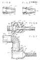
- Alternative embodiments shown in Figures 4 and 5 show a tissue mass removal needle 14 whereby the end of the needle is a flat end wall having a small orifice either adjacent the end wall on the side, as seen as opening 61 in Figure 4, or through the end wall, seen as opening 62 in Figure 5.
- the conduit 59 through the base can be connected to a fluid passage tube system 54 which, in turn, is connected to a source of negative pressure such as an aspiration reservoir, whereby fluid can be aspirated from the area of treatment through the bore 6 0 and out of the eye.
- a source of negative pressure such as an aspiration reservoir
- the negative pressure can be applied to, for example, vitreous strands of unwanted tissue mass and the operator can momentarily energize the vibratory tip to disconnect such stringy mass from the eye structure.
- the flat end wall is advantageous in that it does not extend beyond the sight of the operator and is therefore less likely to do damage to any part of the eye structure. To this end it has been found that when the orifice is on the side of the barrel wall as shown in Figure 4, the distance between the end wall and the center line of the orifice should be as close as possible, and preferably not more than about .035 inches.
- a sheath 40 having a sleeve 42 which is of a length substantially the same length of the operating barrel 14.
- the needle should extend from about 1/16 to about 1/4 inches beyond the sleeve of the attached sheath.
- the sleeve of the present invention is preferably a very thin-walled sleeve having a wall thickness of from about .001 to about .009 inches, and preferably about .004 inches thick and in this case, is preferably reinforced by rib means 43 which extend longitudinally the length of the sleeve.
- a further feature of the sleeve in accordance with the present invention includes openings 44 at the end of the sleeve, which can be tapered, so that treatment fluid provided at such end can be diffused outwardly rather than being directed straight onto the work site from between the sleeve and the barrel of the needle.
- These ribs can be have a dome cross-section and having a dimension of from about .006 to about .012 inches wide and a height of from about .002 to about .006 inches.
- a reservoir 46 which can be an extension of the sleeve at the non operative end and have an enlarged cross-section of from about 0.130 to about 0.145 inches in diameter and a length of from about .005 to about .075 inches so that a reservoir of treatment fluid can be continually provided to the sleeve as treatment fluid is aspirated from the operative site through the needle.
- FIG. 2a an alternate embodiment is shown in which the sheath means has a reservoir with two enlarged cross-sectional dimensions.
- the diameter of the largest enlargement can be the same as indicated above while the smaller dimensioned enlargement can have a diameter of from about .055 to about .120 inches and a length of from about .080 to about .145 inches.
- Sealing means can be provided on the non-operative end of the reservoir so that it fits cooperatively with the sealing means on the base of the needle, and can be in the form of an continuous annular ring 47 or a continuous annular groove 48 (see Figure 6).
- the cross-section can be a dome having a width of from about .007 to about .025 inches, and preferably from about .012 to about .018 inches, and a height from about .010 to about .030 inches, and preferably from about .014 to about .020
- the groove shown in Figure 6 can have a cross-section with a width of from about .006 to about .030 inches and preferably from about .014 to about .022 inches, while the depth of the groove can be from about .006 to about .030 inches, and is preferably from about .012 to about .024 inches.
- the sleeve and needle are of a dimension such that the sleeve can be elastically fit or "snapped" into place and will remain fixed thereon in a sealing fit so that fluid will not pass therefrom nor will the sheath move from the needle.
- the interior surface of the sheath sealing means i.e., the inner surface of the annular ring on the bottom of the groove when they are formed on the sheath, should have a diameter of from about .070 to about .130 inches, and preferably from about .090 to about .100 inches while the sealing means on the needle can have a diameter of from about .040 to about .120, and preferably from about .075 to about .080 inches, that is to say the diameter of the circle defined by the outer surface of the annular ring or the bottom of the groove when they are formed on the needle.
- the fluid passage conduit can be a normal polyethylene or silicone rubber tube normally used in delivery of biological fluids
- the diameter of the connecting aperture can be from about .125 to about .142 inches in diameter.
- the fluid passage means 20 can be either permanently attached by gluing or fusion, or can be removably attached as the need may arise.
- the bore can meet the sleeve conduit at different angles.
- the angle is preferably from about 58 to about 62 degrees, and most preferably about 60 degrees.
- a delivery tube 20" can be provided with a serrated outer surface 24 to relieve outside surface tension on the tube and to reduce deformity of the interior passage 21 of the tube as a result therefrom.
- a fluid supply means may include a container or reservoir 75 of the intravenous type that is being suspended from a support 76.
- treatment fluid such as a saline solution can be continuously fed to the sleeve by the gentle pressure of gravity flow so that the sleeve means is always provided with a continuous supply of fluid.
- the fluid at the operative site is reduced in volume, but as a result of the fluid "well head" built up in the reservoir, treatment fluid is immediately provided to the sleeve so that there is no resulting void in the treatment fluid which can lead to eye structure collapse, etc.
- suitable drugs are administered to dilate the iris to its maximum extent so that a small incision can be made in the transparent cornea as far as possible from the center of the pupil area.
- This incision can be made initially only about 1 to 3 millimeters in length to provide access for a knife to enter the anterior chamber for removal of the anterior capsule.
- the incision be enlarged to 2 to 12 millimeters, usually 4 to 6 millimeters to provide proper access for the operative tip of the vibratory needle and removal of the fragmented mass.
- the present invention permits both mass size reduction and piece removal without increasing the size of the incision.
- the operative tip is inserted into the body of the cataract, whereby the lens tissue mass is broken apart into minute particles.
- a supply of treatment fluid is flowing continuously through the sleeve, while the transducer is energized periodically for very short intervals of time.
- the treatment fluid As the procedure of cataract removal takes place the treatment fluid from the treatment fluid supply enters the work site to keep the eye inflated, by gravity feed.
- the fluid has been described as delivered through the sheath, it may be so delivered by the operating needle and the tissue mass aspiration may be provided through the sheath.
- the first embodiment is believed to be the preferred embodiment. Accordingly, the treatment fluid is supplied from the reservoir of chemical solutions such as saline solution of appropriate type and acts to keep the anterior chamber hydraulically inflated as well as to provide a washing fluid and dispersion fluid at the reduction site.
- the treatment fluid along with particles of mass can be aspirated through the tip of the vibratory needle, and in the event that the entire mass has been reduced sufficiently, one of the flat end needles can be used in this operation in order to prevent any possible injury to the eye structure.
Abstract
Description
- The present invention relates to treatment of biological organisms which includes selective removal of tissue mass therefrom by use of vibrational forces, such as ultrasonic vibrational forces, and in particular, to an apparatus and method for reducing and removing tissue mass from the organism using a treatment fluid.
- The principles of the present invention are broadly applicable to the removal of layers of tissue mass, and are particularly adapted for use in conjunction with removal of organic tissue such as that found in the eye.
- It has been known in the art of removing unwanted tissue mass from animals, such as humans, to effect such removal by use of ultrasonic energy. Specifically, in the art relating to removal of cataracts, it is known to use a tip in the form of a hollow needle which is subjected to ultrasonic vibration, and is surrounded by a plastic tube which is not subjected to vibration. This combined tube and needle can be inserted into the anterior chamber of the eye through a small incision, while provision is made for maintaining hydrodynamic flow both in the area between the needle and the tube and within the interior of the vibrating tube. It is of the greatest importance in prior art procedures that a proper balance be established between the two flows in order to prevent an excessive build up of pressure in the anterior chamber or a reduction in pressure which could cause a collapse of the anterior chamber.
- In order to insure maintenance of this sensitive and delicate balance, practitioners have found it necessary to use a very complex electro-hydraulic means having a series of failsafe characteristics incorporated therein. Moreover, problems can be encountered in insuring that every particle of dispersed cataract material is aspirated before making some unwanted orbit in the anterior chamber. In other words, for example, if a population of 100,000 small particles were created by ultrasonic microchopping, these particles are created in the presence of an inflowing stream of liquid combined with an adjacent rapidly outflowing stream of liquid. The hydrodynamic circulation in the anterior chamber, or in the posterior chamber if that is the area of operation, under these circumstances would allow for the movement in the anterior chamber of those few particles which might accidentally escape from time to time during the operation.
- In the case of hard cataracts such particles could very well have an abrasive character if they were to slide past in contact with the walls of the chamber. In the case of the endothelium of the cornea which forms a part of this chamber, there is extreme sensitivity to any such abrasion and must be avoided at all costs.
- Briefly, the procedure known today, such as disclosed in U.S. Patent No. 3,589,363, includes a process for removal of cataracts by emulsifying the the lens with an ultrasonic probe requiring aspiration of the emulsified material. Since aspiration is a required aspect of the procedure, it is necessary to have complex electronic and hydraulic equipment for delicate control of inflow and outflow in the eye. This complex equipment requires a trained technician to control and monitor such equipment, especially since the aspiration requires very careful manipulation of the tip by the surgeon in order to prevent aspirating other than cataract material.
- It is, therefore, an object of the present invention to provide an improved apparatus and method for removing a mass of tissue from an animal, such as a human.
- Another object of the invention is to provide an improve apparatus and method for removing cataracts.
- A further object of the present invention is to provide an apparatus and method for selectively microchopping and removing layers of living organic tissue from a biological organism.
- Another object of the invention is to provide an apparatus and method for the removal of living organic tissue from a cataract in a rapid manner and with little or no mess created by use of treatment fluids. A further object of the invention is to provide a hydrodynamically balanced fluid flow to the treatment area. other objects and advantages of the present invention will become apparent as the disclosure proceeds.
- The present invention is an apparatus and method for removal of organic tissue from animal, for example, humans, which includes an elongated vibratory instrument, such as a needle, and a sheath device for use with such instrument. The sheath device has a sleeve which has a length sufficient to extend substantially the length of the elongated instrument and which has a wall having a transverse cross-section with the inside perimeter greater than the outside perimeter of a transverse cross-section of the instrument so that fluid introduced to the sleeve means passes between the instrument and the sleeve means. The sheath device also includes a fluid delivery/withdrawal means connected for fluid communication with the sleeve means, and the fluid delivery/withdrawal means has an external port for introducing or withdrawing fluid. The sheath also includes a sealing means which fits cooperatively with the elongated instrument to prevent passage of fluid from the non-operative end of the instrument so that the sheath is capable of being sealingly fitted to the instrument, and so that treatment fluid continuously supplied to the sheath device is maintained at the operative end of the instrument substantially in the absence of interruption in the flow. It is contemplated that the elongated instrument can be a needle which is vibrated in operation, such as between from about 5,000 cycles per second to about 50,000 cycles per second, and preferably at about 27,000 cycles per second. It is important to the present invention that the needle can be vibrated laterally so that the operative end makes essentially an elliptical pattern.
- The needle which can be used as the vibratory instrument includes an elongated barrel means having an operative end and a non-operative end, and is provided with a conduit extending the length thereof with an inlet port at the operative end. The needle also includes a base means provided at the non-operative end of the barrel means in which a connecting conduit is present therethrough so that fluid communication can be made between the barrel conduit and an outlet port at the non-operative end of the base means. The base means also has a connecting means for connecting the needle to a source of vibratory motion. The needle includes a sealing means for sealingly mounting a fluid sheath means on the needle. In the preferred embodiment the needle can be made of a titanium alloy.
- In one embodiment of the present invention the operative end of the barrel is beveled to form an operative edge and the inlet port which, in this case, is the opening formed in the beveled end by the conduit. Another embodiment of the invention includes an end wall on the operative end of the barrel by which the conduit is closed, and an inlet port provided by an opening in the side of the barrel proximal to the end wall. In this latter case the inlet port can have an orifice of between about .020 and about .070 millimeters in diameter, preferably from about .025 to about .055 mm, and most preferably is about .03 millimeters in diameter. Furthermore with regard to this embodiment, since the surgeon or operator can use this needle for removing stringy vitreous material, it is important, therefore, that the end of the barrel does not extend too far past the operating inlet port in order to prevent inadvertent damage to the interior surface of the eye. Accordingly, it has been found that the distance between the outer surface of the end wall and the center line of the orifice should be not more than about .035 inches.
- A further alternative of this latter embodiment of the needle of the present invention has an end wall on the operative end and an inlet port provided by an opening in the end wall. In this embodiment the inlet port is an orifice between about 0.20 and about 0.70 millimeters in diameter, and preferably from about .025 to about .055 mm, while the preferable size includes an orifice having a diameter of about .03 millimeters.
- As indicated before, an alternative of this embodiment includes a sealing means which is a continuous annular groove formed on the outside wall of the needle base, such as by raised flanges, for sealing fit of an annular ring provided on the interior surface of the sheath means. In this case the annular groove can have a cross-sectional width and a cross-sectional depth as set forth before. The annular ring also can have a dome-shaped cross-section with a width and a height as previously indicated.
- In order to achieve a thin-walled sleeve means, it has been found that a reinforcement means can be provided which prevents the wall from longitudinal collapse in the presence of compressive force, such as insertion through a small incision in an eye surface. Specifically, the present invention contemplates the use of at least one rib means extending longitudinally along the wall of the sleeve means, and preferably includes four rib means advantageously spaced around the perimeter of the wall. It is preferred that the rib means be placed on the interior of the wall of the sleeve means and that such ribs have a dome cross-section with a width of from about .006 to about .012 inches and a height from the interior surface of the sleeve means of from about .002 to about .006 inches.
- In the most preferred embodiment of the present invention the sheath means further includes a fluid reservoir means having a dimension sufficient to hold a volume of fluid at least equal to the volume of the fluid held between the instrument and the sleeve means so that a supply of fluid provided by gravity flow is continuously maintained through the sleeve means. Such reservoir means can be an extension of the sleeve means having at least one, and in a preferred embodiment two, enlarged transverse cross-sectional areas and a length sufficient to hold the volume of fluid described above. Preferably the transverse cross-section of the reservoir is substantially circular in shape and, when there are two cross-sectional dimensions, the first one adjacent the barrel conduit can have diameter of from about .130 to about .145 inches and a length of from about .055 to about .075 inches while the second cross-section can be from about .055 to about .120 inches in diameter for a length of from about .008 to about .145 inches.
- The sheath means of the present invention also includes fluid delivery/withdrawal means which can have a body means at the non-operative end of the sleeve means which in turn has a fluid delivery/withdrawal bore extending from an external port and is in fluid communication with either the reservoir or the sleeve means. Furthermore, an attachment means can be provided at the external port of the fluid delivery withdrawal bore for connecting a fluid passage tube. The bore referred to above can meet reservoir or the sleeve means at an angle of from about 45 to about 90 degrees and preferably meets the sleeve means at an angle of about 60 degrees. The bore can be cylindrical and have a transverse cross-section with a diameter of from about .054 to about .062 inches, while the attachment means can be an enlargement in the cross-section dimension of the bore so that a fluid passage tube can be inserted therein. The cross-section of this enlargement can have a diameter of from about .125 to about .142 inches. The present invention can include a fluid passage tube which can be a cylindrical infusion tube made of, for example, polyethylene or silicone rubber, and having a cross-section with an outer diameter of from about .125 to about .142 inches. Depending on the nature of the application, the fluid passage tube can be permanently secured to the attachment means or can be removably attached thereto, such as by friction fit. When the fluid passage tube is a solid-walled tube, the angle at which the bore meets the sleeve is preferably from about 58 to about 62 degrees, and most preferably about 60 degrees, so that the tube can be gently curved at a point proximal to its attachment to the bore.
- In another embodiment when the angle at which the bore meets the barrel conduit is 90 degrees, it is believed that the fluid passage tube should have a substantially serrated outer wall surface profile at a point proximal its attachment to the bore so that the tube can be bent at that point with reduced outer surface tension on the tube and reduced deformity of the interior passage of the tube. In this latter embodiment the wall of the fluid delivery tube can be of from about .024 to about .030 inches thick and the depth of the depressions of the serrations can be from about .010 to about .017 inches. The apexes of said serrations can be either peaks or truncated peaks. Furthermore, in this embodiment, the pitch of the serration can be from about .025 to about .035 inches.
- As a result of the present invention, a highly effective vibratory needle and treatment fluid sheath means can be provided in which treatment fluid can be supplied to the area of operation with the gentle pressure provided by gravity flow without an interruption in said flow or area of negative pressure which could cause collapse of the eye structure, whether it be the anterior or posterior section of the eye. Furthermore, the present invention provides the treatment fluid at the area of operation in the absence of a directed stream which could obfuscate or unduly disperse fragments which must be aspirated from the eye.
- Another advantage realized by the present invention is an inexpensive device for use in cataract removal wherein treatment fluid delivery is used which does not result in a sloppy work area or "wet lap" to the operating surgeon, and which can be thrown away after a single use.
- The laterally vibrating needle of the present invention can be readily applied to the unwanted tissue mass without "plugging" which can result from reciprocating action needles used previously for this purpose. Additional embodiments of the needles of the present invention provide unique "clean up" instruments for use in conjunction with cataract removal, which have heretofore not been known in the art.
- As a further result of the present invention a very small incision can be made in order to insert the highly effective device, since the sleeve wall can be made to be very thin with the help of reinforcing longitudinal ribs. This feature prevents "skinning back" or an "accordion effect." Such reinforcement features also prevent "pinching off" of irrigation flow when the incision may be very small. Another advantage which the ribbed sleeve provides is that it is prevented from contacting the vibrating needle, thereby dampening the vibratory motion.
- The new annular seal feature of the present invention, as mentioned before, provides a fluid reservoir for maintaining the amount of fluid in the sleeve, while at the same time preventing escape of treatment fluid into the surgical area and onto the operator. Furthermore, the annular seal also restricts pulling of the sheath means from the vibratory instrument so that the operating surgeon can rely on a compact unitary combination device throughout the operation.
- For a better understanding of the present invention, together with other and further objects, reference is made to the following description, taken in conjunction with the accompanying drawings, and its scope will be pointed out in the appended claims.
- Preferred embodiments of the invention have been chosen for purposes of illustration and description and are shown in the accompanying drawings, wherein:
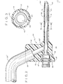
- Figure 1 is an exploded isometric view of a combination apparatus of the present invention;
- Figure la shows one embodiment of a needle cross-section wherein there is provided a means for applying a rotating force to facilitate screwing the needle into a source of vibrating motion;
- Figure 2 depicts an assembly of the needle and sleeve of the present invention in an elevated side view with the sheath means in section;
- Figure 2a shows in partial section an alternative embodiment of the sheath means wherein the reservoir has two enlarged cross-sectional dimensions;
- Figure 3 is a transverse section of the combination sleeve and needle as shown in Figure 2;
- Figures 4 and 5 show additional embodiments of a vibrating needle in accordance with the present invention;
- Figure 6 is a fragmented section of an alternative embodiment of the sealing combination of the needle and sheath means;
- Figure 7 is a fragmented section of an alternate embodiment of the fluid delivery/withdrawal tube as it is connected to the sheath means; and
- Figure 8 depicts an overall operating system in accordance with the present invention.
- The present invention is particularly useful in the removal of unwanted tissue mass from the eye and for use in cleaning such reduced mass from the eye structure. In the surgical procedure for which the present invention has been designed the patient can be given a local anesthetic which consists of, for example, a lid block and a retro- bulbar injection. This local anesthetic is all that is generally required for conventional cataract removal procedures; but in the past it has been known to use a general anesthetic for such procedures in order to prevent movement of the eye during operating procedure.
- After the anesthetic has been administered, a small limbal or fornix based conjunctival flap is performed. Then, a small limbal incision, e.g., less than about six millimeters, and preferably about three to four millimeters, can be made into the anterior chamber of the eye if that is the area on which the operation is to be performed. In the past, in at least one procedure, the aqueous was removed from the anterior chamber while a small amount of air was inserted therein, and a small cystotome would be inserted through the incision to remove the anterior capsule of the lens. However, with the present invention it is not contemplated that the aqueous must be removed. In the event the anterior capsule cannot be completely withdrawn by the cystotome, a small pair of capsule forceps can be inserted to complete the removal.
- At this point in the procedure, a thin-walled, approximately 19 or 20 gage metallic needle, preferably titanium, which can be vibrated with ultrasonic energy, is inserted into the anterior chamber through the incision. As a result of the very thin-walled sheath which can be provided in the present invention, the incision need not be enlarged as has been known in the past when such needle covering devices have been used. Prior to the insertion of the needle, a slow drip of physiological saline is allowed to flow continuously through the tube into the sleeve means. This flow of fluid through the needle is accomplished merely by providing a gravity feed flow from, for example, an intravenous pole arrangement.
- One of the greatest advantages of the present invention is the simplicity of using merely the pressure of gravity, as well as the low pressure flow of the gravity feed system which is more than adequate to permit the inflow of treatment fluid, and consequently, the maintenance of the anterior chamber and removal of fragmented material, without the need for complex irrigation and aspiration controls. In view of this fact an aspiration system can be continuously connected for operation, and it is unnecessary to rely on continuous drainage of lavage fluid to remove of the reduced cataract mass, which results in a sloppy work area, as is disclosed in U.S. Patent Nos. 3,952,732; 3,942,519; and 3,857,387.
- Having positioned the needle to the cataract while viewing the needle and anterial chamber area through an operating microscope and with the flow being in proper adjustment, the tip is ultrasonically energized for a short period of time. In the case of the present invention, the vibration is in a lateral direction thereby producing an essentially elliptical tip path. This ultrasonic energization fragments the material immediately adjacent to the tip. The period during which the tip is energized may vary anywhere from approximately a millisecond to a second, depending on the speed of foot movement in the case of a foot switch which can be provided for the operating surgeon. The surgeon selects the interval of energization to allow complete and perfect control of the operative procedure.
- The mass of material forming the cataract to be removed is initially broken into a plurality of fragmented submasses or major sections which can thereafter be removed in their entirety or further fragmented into a plurality of particle size masses such that it can exit the work area through the aspiration conduit provided in the needle. During the surgical procedure, the surgeon can initially cross drill or bore a plurality of apertures in the cataract to create a tunneling effect and these cross bores or apertures are formed by vibrating the ultrasonic member such that a plurality of submasses are formed during this aspect of the surgical procedure. These submasses are thereafter individually either reduced in size or of an initial size to permit their exiting through the aspiration conduit provided in the needle. In softer cataracts only a small volume of the cataract need be ultrasonically fragmented. This allows a remainder to deform its shape due to the slight hydrostatic pressure differential, and the entire cataract will in a sense flow itself out through the orifice.
- Accordingly, the tip or output edge of the needle- like tool member can be positioned in engagement with the immediate portion of the cataract to be removed, prior to ultrasonically energizing the tip of the needle tool member. Upon energization of the tip of the tool member, a portion of the cataract in surrounding relation thereto is fragmented and the size of the fragmented section is a function of hardness and nature of a cataract material; for example, the fragments may range from practically invisibility to section of millimeter dimensions. These fragments, depending on their size, are lavaged by the continuous stream of irrigation fluid previously described which is provided to the sheath means around the vibrating needle. This product engagement energization tip is repeated until such time as the entire cataract is fragmented and removed from the incision by aspiration. The use of the additional embodiments of the needle tool are ideally suited for removal of reduced cataract mass, without fear of incurring injury to any other parts of the eye.
- Referring to the drawings in detail, it will be seen that the combined
apparatus 10 for ultrasonically removing a tissue mass, such as a cataract from an animal may include an elongated instrument, such as aneedle 12, for effecting the necessary high frequency vibrations of a probe orbarrel 14 which can have a relatively sharp output edge ortip 15 in one embodiment of the invention. Operatively associated with theneedle 12 is a generating means 18 for powering same and a fluid supply means 20 for providing 22 fluid at the operative site. A source of vibratory motion which can be in the form of a handpiece adapted for being hand-held can include a tubular housing 6 with an ultrasonic motor ortransducer 4 being contained therein and having an output end orstem 9 of themotor 4 extending axially beyond the front end of the housing 6 and to which theneedle 12 can be coupled. - In the present invention the
ultrasonic motor 4 is energized by the generator which can be contained in acabinet 1 with a power cable 2 connecting the two together. The generator is an oscillator adapted to produce electrical energy having an ultrasonic frequency and containing a convenient shut off and on switch as well as anactuating foot pedal 3 for use by the operating surgeon. - The
ultrasonic motor 4 may be one of a variety of electromechanical types such as piezoelectric or magneto- strictive. The ultrasonic motor is designed to operate at a desired frequency generally in the range of 5,000 cycles per second to 50,000 cycles per second but preferably in the case of the present invention, in the range of about 27,000 cycles per second and the front output end is adapted to receive the working needle and vibrate such needle in the lateral direction rather than the reciprocal direction as is commonly known in the art. This lateral vibratory motion generally produces an elliptical path at the tip of the operating needle, and prevents unwanted plugging of the needle means aspiration conduit as well as giving the operator a higher degree of control over the area receiving ultra-sonic vibrations. - In the past transducers for such ultrasonic motors have been longitudinally dimensioned so as to have lengths which are whole multiples of half wavelengths of the waves generated therein such that the exterior working end of the ultrasonic motor would be a longitudinal loop of motion. While in the past it has been known to convert this longitudinal motion into lateral motion by use of an angularly fitted needle means, the present invention includes a transducer which provides lateral vibratory motion without the use of an angularly fitted needle. The amplitude of the vibration is generally in the range of 0.0001 to 0.010 and the hyper accelerations exceed 1,000 g at the
tool tip 15. The design of the output end of themotor 4 and thetool tip 15 may be designed to either magnify or reduce the amplitude of the vibrations received from theultrasonic motor 4. - As indicated.before, the
tool 14 may be a needle- like member having a base 56 with a threadedportion 58 which is adapted to connect with complementary threads in theoutput end 9 of the handpiece 8 and in the present invention has anaxially extending conduit 60 extending from the opening at the front end to the rear thereof to meet with a connectingconduit 59 formed in the base 56 which is in fluid communication withconduit 60. In this way a fluid is permitted to enter the front of theneedle 14 and pass therethrough as hereinafter explained in detail. The base 56 can also be provided with a sealing means such as acontinuous groove 66 or a continuousangular rib 68 which can be sealingly cooperatively fit with the sheath means 40. Referring to Figure la, theneedle 12 can also be formed with a flattenedouter surface 11 adjacentannular flanges 67, which formgrove 66, to facilitate application of rotational force to the needle. - The
needle 12 has integrally formed therewith abarrel portion 14 and abore 60 extending axially therethrough to provide fluid passage. Theoperative tip 15 is preferably formed of an extremely hard, sterilizable material, such as titanium, and for most surgical applications is made of extremely small dimension. Since this is the only portion of the instrument that is brought into contact with the tissue to be broken apart and removed, it will be evident that only a very short incision need to be made in the outer surface to permit access of the tip. Preferably the outer diameter of the transverse section of thebarrel portion 14 can be in the range of 0.31 inches to about 0.44 inches but is preferably in a range of from about .035 inches to about .042 inches. Theconduit 60 should be of a size to permit continuous flow of fluid along with reduced tissue mass therethrough, e.g., from about .024 to about .042 inches, and preferably from about .028 to about .035 inches. - As seen in Figure 2, an acute tapered angle 72 is provided in one embodiment to leave a relatively sharp, rounded
edge 15. The shape, length, and dimensions of the tool member may vary depending on the type of mass or cataract to be removed. Alternative embodiments shown in Figures 4 and 5 show a tissuemass removal needle 14 whereby the end of the needle is a flat end wall having a small orifice either adjacent the end wall on the side, as seen as opening 61 in Figure 4, or through the end wall, seen as opening 62 in Figure 5. - While in operation, the
conduit 59 through the base can be connected to a fluid passage tube system 54 which, in turn, is connected to a source of negative pressure such as an aspiration reservoir, whereby fluid can be aspirated from the area of treatment through the bore 60 and out of the eye. When using the tissue removal needles shown in Figures 4 and 5, the negative pressure can be applied to, for example, vitreous strands of unwanted tissue mass and the operator can momentarily energize the vibratory tip to disconnect such stringy mass from the eye structure. The flat end wall is advantageous in that it does not extend beyond the sight of the operator and is therefore less likely to do damage to any part of the eye structure. To this end it has been found that when the orifice is on the side of the barrel wall as shown in Figure 4, the distance between the end wall and the center line of the orifice should be as close as possible, and preferably not more than about .035 inches. - Referring now to the sheath means in the combination of the present invention, there can be seen in Figures 1 and 2 a
sheath 40 having asleeve 42, which is of a length substantially the same length of the operatingbarrel 14. In one embodiment it is known that the needle should extend from about 1/16 to about 1/4 inches beyond the sleeve of the attached sheath. Furthermore, the sleeve of the present invention is preferably a very thin-walled sleeve having a wall thickness of from about .001 to about .009 inches, and preferably about .004 inches thick and in this case, is preferably reinforced by rib means 43 which extend longitudinally the length of the sleeve. A further feature of the sleeve in accordance with the present invention includesopenings 44 at the end of the sleeve, which can be tapered, so that treatment fluid provided at such end can be diffused outwardly rather than being directed straight onto the work site from between the sleeve and the barrel of the needle. Preferably there are fourribs 43 provided around the interior circumference of the sleeve in order to prevent collapse or skinning back in response to compressive force applied thereto when thecombination apparatus 10 is inserted into the eye. These ribs can be have a dome cross-section and having a dimension of from about .006 to about .012 inches wide and a height of from about .002 to about .006 inches. - In further reference to the sheath, there can be provided a
reservoir 46 which can be an extension of the sleeve at the non operative end and have an enlarged cross-section of from about 0.130 to about 0.145 inches in diameter and a length of from about .005 to about .075 inches so that a reservoir of treatment fluid can be continually provided to the sleeve as treatment fluid is aspirated from the operative site through the needle. - In Figure 2a an alternate embodiment is shown in which the sheath means has a reservoir with two enlarged cross-sectional dimensions. The diameter of the largest enlargement can be the same as indicated above while the smaller dimensioned enlargement can have a diameter of from about .055 to about .120 inches and a length of from about .080 to about .145 inches.
- Sealing means can be provided on the non-operative end of the reservoir so that it fits cooperatively with the sealing means on the base of the needle, and can be in the form of an continuous
annular ring 47 or a continuous annular groove 48 (see Figure 6). In the case of a continuous annular ring the cross-section can be a dome having a width of from about .007 to about .025 inches, and preferably from about .012 to about .018 inches, and a height from about .010 to about .030 inches, and preferably from about .014 to about .020, whereas the groove shown in Figure 6 can have a cross-section with a width of from about .006 to about .030 inches and preferably from about .014 to about .022 inches, while the depth of the groove can be from about .006 to about .030 inches, and is preferably from about .012 to about .024 inches. In any event, the sleeve and needle are of a dimension such that the sleeve can be elastically fit or "snapped" into place and will remain fixed thereon in a sealing fit so that fluid will not pass therefrom nor will the sheath move from the needle. In order to achieve this it is believed that the interior surface of the sheath sealing means, i.e., the inner surface of the annular ring on the bottom of the groove when they are formed on the sheath, should have a diameter of from about .070 to about .130 inches, and preferably from about .090 to about .100 inches while the sealing means on the needle can have a diameter of from about .040 to about .120, and preferably from about .075 to about .080 inches, that is to say the diameter of the circle defined by the outer surface of the annular ring or the bottom of the groove when they are formed on the needle. - Finally, with reference to the sleeve there can be seen a
housing 41 and abore 43 that meets the rear part of the sleeve conduit or the reservoir at an angle of from about 450 to about 90° degrees, and has anenlarged section 98 for receipt of fluid passage tube therein. Since the fluid passage conduit can be a normal polyethylene or silicone rubber tube normally used in delivery of biological fluids, the diameter of the connecting aperture can be from about .125 to about .142 inches in diameter. Furthermore, the fluid passage means 20 can be either permanently attached by gluing or fusion, or can be removably attached as the need may arise. - In order to facilitate fabrication of the sleeve and to accommodate various types of systems, the bore can meet the sleeve conduit at different angles. For example, when the fluid passage tube is a solid-walled tube 20', the angle is preferably from about 58 to about 62 degrees, and most preferably about 60 degrees. In order to provide a 90 degree angle junction between the bore and the sleeve conduit a
delivery tube 20" can be provided with a serratedouter surface 24 to relieve outside surface tension on the tube and to reduce deformity of theinterior passage 21 of the tube as a result therefrom. - A fluid supply means may include a container or
reservoir 75 of the intravenous type that is being suspended from asupport 76. In operation treatment fluid such a saline solution can be continuously fed to the sleeve by the gentle pressure of gravity flow so that the sleeve means is always provided with a continuous supply of fluid. During periods of aspiration, the fluid at the operative site is reduced in volume, but as a result of the fluid "well head" built up in the reservoir, treatment fluid is immediately provided to the sleeve so that there is no resulting void in the treatment fluid which can lead to eye structure collapse, etc. - In use of the instrument of the present invention, suitable drugs are administered to dilate the iris to its maximum extent so that a small incision can be made in the transparent cornea as far as possible from the center of the pupil area. This incision can be made initially only about 1 to 3 millimeters in length to provide access for a knife to enter the anterior chamber for removal of the anterior capsule. In the past after the capsule had been removed, it was necessary that the incision be enlarged to 2 to 12 millimeters, usually 4 to 6 millimeters to provide proper access for the operative tip of the vibratory needle and removal of the fragmented mass. However, the present invention permits both mass size reduction and piece removal without increasing the size of the incision.
- After the capsule is removed with a surgical instrument, the operative tip is inserted into the body of the cataract, whereby the lens tissue mass is broken apart into minute particles. During this portion of the operation, as well as others, a supply of treatment fluid is flowing continuously through the sleeve, while the transducer is energized periodically for very short intervals of time.
- As the procedure of cataract removal takes place the treatment fluid from the treatment fluid supply enters the work site to keep the eye inflated, by gravity feed. Although the fluid has been described as delivered through the sheath, it may be so delivered by the operating needle and the tissue mass aspiration may be provided through the sheath. However, the first embodiment is believed to be the preferred embodiment. Accordingly, the treatment fluid is supplied from the reservoir of chemical solutions such as saline solution of appropriate type and acts to keep the anterior chamber hydraulically inflated as well as to provide a washing fluid and dispersion fluid at the reduction site.
- In order to remove the reduced tissue mass the treatment fluid along with particles of mass can be aspirated through the tip of the vibratory needle, and in the event that the entire mass has been reduced sufficiently, one of the flat end needles can be used in this operation in order to prevent any possible injury to the eye structure.
- The practitioner will realize many different advantages and alternative procedures which can be employed using the apparatus and method contemplated by the present invention.
- Thus, while there have been described what are presently believed to be the preferred embodiments of the invention, those skilled in the art will realize that changes and modifications may be made thereto without departing from the spirit of the invention, and it is intended to claim all such changes and modifications as fall within the true scope of the invention.
Claims (35)
whereby said sheath is capable of being sealingly fitted to said instrument and whereby treatment fluid continuously supplied to said sheath device is maintained at said operative end of said elongated instrument substantially in the absence of interruption in flow.
Applications Claiming Priority (2)
| Application Number | Priority Date | Filing Date | Title |
|---|---|---|---|
| US06/662,843 US4634420A (en) | 1984-10-31 | 1984-10-31 | Apparatus and method for removing tissue mass from an organism |
| US662843 | 1984-10-31 |
Publications (2)
| Publication Number | Publication Date |
|---|---|
| EP0180214A2 true EP0180214A2 (en) | 1986-05-07 |
| EP0180214A3 EP0180214A3 (en) | 1988-08-10 |
Family
ID=24659455
Family Applications (1)
| Application Number | Title | Priority Date | Filing Date |
|---|---|---|---|
| EP85113829A Withdrawn EP0180214A3 (en) | 1984-10-31 | 1985-10-30 | Apparatus and method for removing tissue mass from an organism |
Country Status (3)
| Country | Link |
|---|---|
| US (1) | US4634420A (en) |
| EP (1) | EP0180214A3 (en) |
| JP (1) | JPS61179150A (en) |
Cited By (8)
| Publication number | Priority date | Publication date | Assignee | Title |
|---|---|---|---|---|
| GB2222952A (en) * | 1988-09-23 | 1990-03-28 | Vnii Glaznykh Boleznei | Ophthalmologlcal device |
| US4970656A (en) * | 1986-11-07 | 1990-11-13 | Alcon Laboratories, Inc. | Analog drive for ultrasonic probe with tunable phase angle |
| US5001649A (en) * | 1987-04-06 | 1991-03-19 | Alcon Laboratories, Inc. | Linear power control for ultrasonic probe with tuned reactance |
| EP0711128A1 (en) * | 1993-04-15 | 1996-05-15 | Ethicon Endo-Surgery, Inc. | Ultrasonic surgical instrument and methods for manufacturing |
| WO1997007755A1 (en) * | 1995-08-28 | 1997-03-06 | Alcon Laboratories, Inc. | Phacoemulsification sleeve |
| WO1997028769A1 (en) * | 1996-02-12 | 1997-08-14 | Alcon Laboratories, Inc. | Infusion sleeve |
| WO2008079706A1 (en) * | 2006-12-21 | 2008-07-03 | Bausch & Lomb Incorporated | A rigid sleeve phacoemulsification needle |
| CN108472154A (en) * | 2015-12-16 | 2018-08-31 | 诺华股份有限公司 | The device and method for treating material application device for being intubated delivery type |
Families Citing this family (272)
| Publication number | Priority date | Publication date | Assignee | Title |
|---|---|---|---|---|
| US4681561A (en) * | 1986-01-24 | 1987-07-21 | Coopervision, Inc. | Ultrasonic decoupling sleeve |
| US4988334A (en) * | 1986-04-09 | 1991-01-29 | Valleylab, Inc. | Ultrasonic surgical system with aspiration tubulation connector |
| JPH0324171Y2 (en) * | 1986-10-16 | 1991-05-27 | ||
| US4808153A (en) * | 1986-11-17 | 1989-02-28 | Ultramed Corporation | Device for removing plaque from arteries |
| SE459711B (en) * | 1987-03-20 | 1989-07-31 | Swedemed Ab | EQUIPMENT FOR USE IN SURGICAL INTERVENTIONS TO DISPOSE TISSUE |
| US5178135A (en) * | 1987-04-16 | 1993-01-12 | Olympus Optical Co., Ltd. | Therapeutical apparatus of extracorporeal type |
| US5065741A (en) * | 1987-04-16 | 1991-11-19 | Olympus Optical Co. Ltd. | Extracoporeal ultrasonic lithotripter with a variable focus |
| US5019038A (en) * | 1989-10-25 | 1991-05-28 | Hall Surgical Division Of Zimmer Inc. | Irrigation system for surgical procedures |
| EP0424685B1 (en) * | 1989-10-27 | 1995-05-10 | Storz Instrument Company | Method for driving an ultrasonic transducer |
| US5344395A (en) * | 1989-11-13 | 1994-09-06 | Scimed Life Systems, Inc. | Apparatus for intravascular cavitation or delivery of low frequency mechanical energy |
| US5492528A (en) * | 1990-07-17 | 1996-02-20 | Anis; Azis Y. | Removal of tissue |
| US6007513A (en) * | 1990-07-17 | 1999-12-28 | Aziz Yehia Anis | Removal of tissue |
| US5722945A (en) * | 1990-07-17 | 1998-03-03 | Aziz Yehia Anis | Removal of tissue |
| US5911699A (en) | 1990-07-17 | 1999-06-15 | Aziz Yehia Anis | Removal of tissue |
| CA2071760A1 (en) * | 1991-09-23 | 1993-03-24 | Alexander Ureche | Infusion sleeve for surgical ultrasonic apparatus |
| US5188589A (en) * | 1991-10-10 | 1993-02-23 | Alcon Surgical, Inc. | Textured irrigating sleeve |
| DE4134428A1 (en) * | 1991-10-18 | 1993-04-22 | Irmer Joachim | DEVICE FOR GENERATING VIBRATIONS |
| US5197947A (en) * | 1991-10-24 | 1993-03-30 | University Of New Mexico | Powered clysis and clyser |
| US5199943A (en) * | 1991-12-12 | 1993-04-06 | Alcon Surgical, Inc. | Ultrasonic surgical handpiece |
| US5261922A (en) * | 1992-02-20 | 1993-11-16 | Hood Larry L | Improved ultrasonic knife |
| US5695510A (en) * | 1992-02-20 | 1997-12-09 | Hood; Larry L. | Ultrasonic knife |
| US5547376A (en) * | 1992-06-18 | 1996-08-20 | Harrel; Stephen K. | Methods and apparatus for containing and recovering abrasive powders from an abrasive polisher |
| US5378150A (en) * | 1992-06-18 | 1995-01-03 | Harrel; Stephen K. | Methods and apparatus for controlling the aerosol envelope generated by ultrasonic devices |
| AU4773393A (en) * | 1992-07-15 | 1994-02-14 | University Of Miami | Surgical cutting heads |
| US5613972A (en) * | 1992-07-15 | 1997-03-25 | The University Of Miami | Surgical cutting heads with curled cutting wings |
| US5470305A (en) | 1993-04-19 | 1995-11-28 | Stryker Corporation | Irrigation handpiece with built in pulsing pump |
| US6746419B1 (en) | 1993-04-19 | 2004-06-08 | Stryker Corporation | Irrigation handpiece with built in pulsing pump |
| US5728089A (en) * | 1993-06-04 | 1998-03-17 | The Regents Of The University Of California | Microfabricated structure to be used in surgery |
| FR2708193B1 (en) * | 1993-06-29 | 1996-07-05 | Satelec Sa | Surgical instrument, intended in particular for dental surgery. |
| US6213970B1 (en) * | 1993-12-30 | 2001-04-10 | Stryker Corporation | Surgical suction irrigation |
| AUPM784494A0 (en) * | 1994-09-02 | 1994-09-22 | Oversby Pty Ltd | A phacoemulsification needle |
| WO1996007377A1 (en) * | 1994-09-02 | 1996-03-14 | Oversby Pty. Ltd. | Grooved phaco-emulsification needle |
| US5520635A (en) * | 1994-12-16 | 1996-05-28 | Gelbfish; Gary A. | Method and associated device for removing clot |
| US5928218A (en) * | 1994-12-16 | 1999-07-27 | Gelbfish; Gary A. | Medical material removal method and associated instrumentation |
| US5628743A (en) * | 1994-12-21 | 1997-05-13 | Valleylab Inc. | Dual mode ultrasonic surgical apparatus |
| US5505693A (en) * | 1994-12-30 | 1996-04-09 | Mackool; Richard J. | Method and apparatus for reducing friction and heat generation by an ultrasonic device during surgery |
| US5899693A (en) * | 1996-04-12 | 1999-05-04 | Hakusui Trading Co., Ltd | Dental tip jig and dental tip fitted with it |
| US5984904A (en) * | 1996-08-22 | 1999-11-16 | Bausch & Lomb Surgical, Inc. | Sleeve for a surgical instrument |
| US5941887A (en) * | 1996-09-03 | 1999-08-24 | Bausch & Lomb Surgical, Inc. | Sleeve for a surgical instrument |
| US5676649A (en) * | 1996-10-04 | 1997-10-14 | Alcon Laboratories, Inc. | Phacoemulsification cutting tip |
| US6013046A (en) * | 1996-10-16 | 2000-01-11 | Surgin Surgical Instrumentation, Inc. | Sleeve shielded needles for phaco-emulsification devices |
| US6206844B1 (en) | 1997-02-28 | 2001-03-27 | Ethicon Endo-Surgery, Inc. | Reusable ultrasonic surgical instrument with removable outer sheath |
| US6033395A (en) * | 1997-11-03 | 2000-03-07 | Peyman; Gholam A. | System and method for modifying a live cornea via laser ablation and mechanical erosion |
| US5935144A (en) * | 1998-04-09 | 1999-08-10 | Ethicon Endo-Surgery, Inc. | Double sealed acoustic isolation members for ultrasonic |
| US6196989B1 (en) | 1998-06-04 | 2001-03-06 | Alcon Laboratories, Inc. | Tip for liquefracture handpiece |
| US6398759B1 (en) | 1998-06-04 | 2002-06-04 | Alcon Manufacturing, Ltd. | Liquefracture handpiece tip |
| US6179805B1 (en) | 1998-06-04 | 2001-01-30 | Alcon Laboratories, Inc. | Liquefracture handpiece |
| US6579270B2 (en) | 1998-06-04 | 2003-06-17 | Alcon Manufacturing, Ltd. | Liquefracture handpiece tip |
| US6589201B1 (en) | 1998-06-04 | 2003-07-08 | Alcon Manufacturing, Ltd. | Liquefracture handpiece tip |
| US6331171B1 (en) | 1998-06-04 | 2001-12-18 | Alcon Laboratories, Inc. | Tip for a liquefracture handpiece |
| US6231578B1 (en) | 1998-08-05 | 2001-05-15 | United States Surgical Corporation | Ultrasonic snare for excising tissue |
| US6156036A (en) * | 1999-06-11 | 2000-12-05 | Alcon Laboratories, Inc. | Surgical handpiece tip |
| DE19932032C2 (en) * | 1999-07-09 | 2003-07-24 | Eppendorf Ag | Tissue micro-dissection device |
| US20050119679A1 (en) * | 1999-10-05 | 2005-06-02 | Omnisonics Medical Technologies, Inc. | Apparatus and method for an ultrasonic medical device to treat chronic total occlusions |
| US6551337B1 (en) * | 1999-10-05 | 2003-04-22 | Omnisonics Medical Technologies, Inc. | Ultrasonic medical device operating in a transverse mode |
| US6660013B2 (en) | 1999-10-05 | 2003-12-09 | Omnisonics Medical Technologies, Inc. | Apparatus for removing plaque from blood vessels using ultrasonic energy |
| US20050043753A1 (en) * | 1999-10-05 | 2005-02-24 | Omnisonics Medical Technologies, Inc. | Apparatus and method for an ultrasonic medical device to treat peripheral artery disease |
| US20040158150A1 (en) * | 1999-10-05 | 2004-08-12 | Omnisonics Medical Technologies, Inc. | Apparatus and method for an ultrasonic medical device for tissue remodeling |
| US20050043629A1 (en) * | 1999-10-05 | 2005-02-24 | Omnisonics Medical Technologies, Inc. | Apparatus and method for an ultrasonic medical device having a probe with a small proximal end |
| US20030065263A1 (en) * | 1999-10-05 | 2003-04-03 | Omnisonics Medical Technologies, Inc. | Ultrasonic probe device with rapid attachment and detachment means having a line contact collet |
| US20030236539A1 (en) * | 1999-10-05 | 2003-12-25 | Omnisonics Medical Technologies, Inc. | Apparatus and method for using an ultrasonic probe to clear a vascular access device |
| US20040249401A1 (en) * | 1999-10-05 | 2004-12-09 | Omnisonics Medical Technologies, Inc. | Apparatus and method for an ultrasonic medical device with a non-compliant balloon |
| US20050096669A1 (en) * | 1999-10-05 | 2005-05-05 | Omnisonics Medical Technologies, Inc. | Apparatus and method for an ultrasonic medical device to treat coronary thrombus bearing lesions |
| US6733451B2 (en) | 1999-10-05 | 2004-05-11 | Omnisonics Medical Technologies, Inc. | Apparatus and method for an ultrasonic probe used with a pharmacological agent |
| US6695782B2 (en) | 1999-10-05 | 2004-02-24 | Omnisonics Medical Technologies, Inc. | Ultrasonic probe device with rapid attachment and detachment means |
| US20040097996A1 (en) | 1999-10-05 | 2004-05-20 | Omnisonics Medical Technologies, Inc. | Apparatus and method of removing occlusions using an ultrasonic medical device operating in a transverse mode |
| US6537205B1 (en) * | 1999-10-14 | 2003-03-25 | Scimed Life Systems, Inc. | Endoscopic instrument system having reduced backlash control wire action |
| AU2001234738A1 (en) | 2000-02-03 | 2001-08-14 | Sound Surgical Technologies Llc | Ultrasonic cutting and coagulation knife using transverse vibrations |
| US6702761B1 (en) | 2000-03-06 | 2004-03-09 | Fonar Corporation | Vibration assisted needle device |
| TW504425B (en) | 2000-03-30 | 2002-10-01 | Electro Scient Ind Inc | Laser system and method for single pass micromachining of multilayer workpieces |
| US6638249B1 (en) | 2000-07-17 | 2003-10-28 | Wisconsin Alumni Research Foundation | Ultrasonically actuated needle pump system |
| US6652488B1 (en) | 2000-09-11 | 2003-11-25 | Stryker Corporation | Surgical suction irrigator |
| US6740058B2 (en) | 2001-06-08 | 2004-05-25 | Wisconsin Alumni Research Foundation | Surgical tool with integrated pressure and flow sensors |
| US10835307B2 (en) | 2001-06-12 | 2020-11-17 | Ethicon Llc | Modular battery powered handheld surgical instrument containing elongated multi-layered shaft |
| US6893261B1 (en) * | 2001-08-29 | 2005-05-17 | James Feine | Miniature ultrasonic footswitch generator for dental scaling and method |
| US20040030349A1 (en) * | 2002-08-08 | 2004-02-12 | Mikhail Boukhny | Liquefaction handpiece tip |
| US7014629B2 (en) * | 2002-12-13 | 2006-03-21 | Alcon, Inc | Tapered infusion sleeve portal |
| WO2004089229A1 (en) * | 2003-04-01 | 2004-10-21 | William A. Cook Australia Pty. Ltd. | Aspiration and flushing needle |
| US20040267298A1 (en) * | 2003-06-30 | 2004-12-30 | Sound Surgical Technologies Llc | Ultrasonic cutting and coagulation knife using transverse vibrations |
| US20050187514A1 (en) * | 2004-02-09 | 2005-08-25 | Omnisonics Medical Technologies, Inc. | Apparatus and method for an ultrasonic medical device operating in a torsional mode |
| US7794414B2 (en) * | 2004-02-09 | 2010-09-14 | Emigrant Bank, N.A. | Apparatus and method for an ultrasonic medical device operating in torsional and transverse modes |
| US7276060B2 (en) * | 2004-02-26 | 2007-10-02 | Alcon, Inc. | Surgical handpiece tip |
| US8182501B2 (en) | 2004-02-27 | 2012-05-22 | Ethicon Endo-Surgery, Inc. | Ultrasonic surgical shears and method for sealing a blood vessel using same |
| US20050267488A1 (en) * | 2004-05-13 | 2005-12-01 | Omnisonics Medical Technologies, Inc. | Apparatus and method for using an ultrasonic medical device to treat urolithiasis |
| US20050256410A1 (en) * | 2004-05-14 | 2005-11-17 | Omnisonics Medical Technologies, Inc. | Apparatus and method for an ultrasonic probe capable of bending with aid of a balloon |
| US7857794B2 (en) | 2004-06-14 | 2010-12-28 | Alcon, Inc. | Handpiece tip |
| US8328810B2 (en) | 2004-06-17 | 2012-12-11 | Boston Scientific Scimed, Inc. | Slidable sheaths for tissue removal devices |
| AU2005295010B2 (en) | 2004-10-08 | 2012-05-31 | Ethicon Endo-Surgery, Inc. | Ultrasonic surgical instrument |
| US20060116610A1 (en) * | 2004-11-30 | 2006-06-01 | Omnisonics Medical Technologies, Inc. | Apparatus and method for an ultrasonic medical device with variable frequency drive |
| US7967799B2 (en) * | 2005-03-16 | 2011-06-28 | Alcon, Inc. | Liquefaction handpiece tip |
| US20070149919A1 (en) * | 2005-07-21 | 2007-06-28 | Bausch & Lomb Incorporated | Concentric thin wall surgical irrigation tubing |
| US20070032777A1 (en) * | 2005-07-21 | 2007-02-08 | Perkins James T | Concentric thin wall surgical irrigation tubing |
| US20070191713A1 (en) | 2005-10-14 | 2007-08-16 | Eichmann Stephen E | Ultrasonic device for cutting and coagulating |
| US7621930B2 (en) | 2006-01-20 | 2009-11-24 | Ethicon Endo-Surgery, Inc. | Ultrasound medical instrument having a medical ultrasonic blade |
| US7967775B2 (en) * | 2007-01-09 | 2011-06-28 | Alcon, Inc. | Irrigation/aspiration tip |
| US8226675B2 (en) | 2007-03-22 | 2012-07-24 | Ethicon Endo-Surgery, Inc. | Surgical instruments |
| US8911460B2 (en) | 2007-03-22 | 2014-12-16 | Ethicon Endo-Surgery, Inc. | Ultrasonic surgical instruments |
| US8142461B2 (en) | 2007-03-22 | 2012-03-27 | Ethicon Endo-Surgery, Inc. | Surgical instruments |
| US20080234709A1 (en) | 2007-03-22 | 2008-09-25 | Houser Kevin L | Ultrasonic surgical instrument and cartilage and bone shaping blades therefor |
| US8057498B2 (en) | 2007-11-30 | 2011-11-15 | Ethicon Endo-Surgery, Inc. | Ultrasonic surgical instrument blades |
| US8882791B2 (en) | 2007-07-27 | 2014-11-11 | Ethicon Endo-Surgery, Inc. | Ultrasonic surgical instruments |
| US8808319B2 (en) | 2007-07-27 | 2014-08-19 | Ethicon Endo-Surgery, Inc. | Surgical instruments |
| US8523889B2 (en) | 2007-07-27 | 2013-09-03 | Ethicon Endo-Surgery, Inc. | Ultrasonic end effectors with increased active length |
| US8348967B2 (en) | 2007-07-27 | 2013-01-08 | Ethicon Endo-Surgery, Inc. | Ultrasonic surgical instruments |
| US8257377B2 (en) * | 2007-07-27 | 2012-09-04 | Ethicon Endo-Surgery, Inc. | Multiple end effectors ultrasonic surgical instruments |
| US8512365B2 (en) | 2007-07-31 | 2013-08-20 | Ethicon Endo-Surgery, Inc. | Surgical instruments |
| US8252012B2 (en) | 2007-07-31 | 2012-08-28 | Ethicon Endo-Surgery, Inc. | Ultrasonic surgical instrument with modulator |
| US8430898B2 (en) | 2007-07-31 | 2013-04-30 | Ethicon Endo-Surgery, Inc. | Ultrasonic surgical instruments |
| US9044261B2 (en) | 2007-07-31 | 2015-06-02 | Ethicon Endo-Surgery, Inc. | Temperature controlled ultrasonic surgical instruments |
| US8235042B2 (en) * | 2007-08-31 | 2012-08-07 | Wet Nose Technologies, Llc | Exhalatory pressure device and system thereof |
| US8225787B2 (en) * | 2007-08-31 | 2012-07-24 | Wet Nose Technologies, Llc | Adjustable pressure device and system thereof |
| US9427504B2 (en) * | 2007-09-01 | 2016-08-30 | Wet Nose Technologies, Llc | Medical apparatus for suction and combination irrigation and suction |
| USD594983S1 (en) | 2007-10-05 | 2009-06-23 | Ethicon Endo-Surgery, Inc. | Handle assembly for surgical instrument |
| US8623027B2 (en) * | 2007-10-05 | 2014-01-07 | Ethicon Endo-Surgery, Inc. | Ergonomic surgical instruments |
| US10010339B2 (en) | 2007-11-30 | 2018-07-03 | Ethicon Llc | Ultrasonic surgical blades |
| US7901423B2 (en) | 2007-11-30 | 2011-03-08 | Ethicon Endo-Surgery, Inc. | Folded ultrasonic end effectors with increased active length |
| US20100152646A1 (en) * | 2008-02-29 | 2010-06-17 | Reshma Girijavallabhan | Intravitreal injection device and method |
| US8058771B2 (en) | 2008-08-06 | 2011-11-15 | Ethicon Endo-Surgery, Inc. | Ultrasonic device for cutting and coagulating with stepped output |
| US9089360B2 (en) | 2008-08-06 | 2015-07-28 | Ethicon Endo-Surgery, Inc. | Devices and techniques for cutting and coagulating tissue |
| US20100057118A1 (en) * | 2008-09-03 | 2010-03-04 | Dietz Timothy G | Ultrasonic surgical blade |
| US8783247B2 (en) * | 2009-02-04 | 2014-07-22 | Wet Nose Technologies, Llc. | Pressure release systems, apparatus and methods |
| US9700339B2 (en) | 2009-05-20 | 2017-07-11 | Ethicon Endo-Surgery, Inc. | Coupling arrangements and methods for attaching tools to ultrasonic surgical instruments |
| US8344596B2 (en) | 2009-06-24 | 2013-01-01 | Ethicon Endo-Surgery, Inc. | Transducer arrangements for ultrasonic surgical instruments |
| US9017326B2 (en) | 2009-07-15 | 2015-04-28 | Ethicon Endo-Surgery, Inc. | Impedance monitoring apparatus, system, and method for ultrasonic surgical instruments |
| US8663220B2 (en) | 2009-07-15 | 2014-03-04 | Ethicon Endo-Surgery, Inc. | Ultrasonic surgical instruments |
| US8461744B2 (en) | 2009-07-15 | 2013-06-11 | Ethicon Endo-Surgery, Inc. | Rotating transducer mount for ultrasonic surgical instruments |
| US10172669B2 (en) | 2009-10-09 | 2019-01-08 | Ethicon Llc | Surgical instrument comprising an energy trigger lockout |
| US9168054B2 (en) | 2009-10-09 | 2015-10-27 | Ethicon Endo-Surgery, Inc. | Surgical generator for ultrasonic and electrosurgical devices |
| US10441345B2 (en) | 2009-10-09 | 2019-10-15 | Ethicon Llc | Surgical generator for ultrasonic and electrosurgical devices |
| US11090104B2 (en) | 2009-10-09 | 2021-08-17 | Cilag Gmbh International | Surgical generator for ultrasonic and electrosurgical devices |
| US8951248B2 (en) * | 2009-10-09 | 2015-02-10 | Ethicon Endo-Surgery, Inc. | Surgical generator for ultrasonic and electrosurgical devices |
| USRE47996E1 (en) | 2009-10-09 | 2020-05-19 | Ethicon Llc | Surgical generator for ultrasonic and electrosurgical devices |
| JP2011120685A (en) * | 2009-12-09 | 2011-06-23 | Univ Of Tsukuba | Treatment apparatus |
| US8382782B2 (en) | 2010-02-11 | 2013-02-26 | Ethicon Endo-Surgery, Inc. | Ultrasonic surgical instruments with partially rotating blade and fixed pad arrangement |
| US8961547B2 (en) | 2010-02-11 | 2015-02-24 | Ethicon Endo-Surgery, Inc. | Ultrasonic surgical instruments with moving cutting implement |
| US9259234B2 (en) | 2010-02-11 | 2016-02-16 | Ethicon Endo-Surgery, Llc | Ultrasonic surgical instruments with rotatable blade and hollow sheath arrangements |
| US8951272B2 (en) | 2010-02-11 | 2015-02-10 | Ethicon Endo-Surgery, Inc. | Seal arrangements for ultrasonically powered surgical instruments |
| US8419759B2 (en) * | 2010-02-11 | 2013-04-16 | Ethicon Endo-Surgery, Inc. | Ultrasonic surgical instrument with comb-like tissue trimming device |
| US8531064B2 (en) * | 2010-02-11 | 2013-09-10 | Ethicon Endo-Surgery, Inc. | Ultrasonically powered surgical instruments with rotating cutting implement |
| US8486096B2 (en) | 2010-02-11 | 2013-07-16 | Ethicon Endo-Surgery, Inc. | Dual purpose surgical instrument for cutting and coagulating tissue |
| US8469981B2 (en) | 2010-02-11 | 2013-06-25 | Ethicon Endo-Surgery, Inc. | Rotatable cutting implement arrangements for ultrasonic surgical instruments |
| US8579928B2 (en) | 2010-02-11 | 2013-11-12 | Ethicon Endo-Surgery, Inc. | Outer sheath and blade arrangements for ultrasonic surgical instruments |
| US8323302B2 (en) | 2010-02-11 | 2012-12-04 | Ethicon Endo-Surgery, Inc. | Methods of using ultrasonically powered surgical instruments with rotatable cutting implements |
| GB2480498A (en) | 2010-05-21 | 2011-11-23 | Ethicon Endo Surgery Inc | Medical device comprising RF circuitry |
| US8795327B2 (en) | 2010-07-22 | 2014-08-05 | Ethicon Endo-Surgery, Inc. | Electrosurgical instrument with separate closure and cutting members |
| US9192431B2 (en) | 2010-07-23 | 2015-11-24 | Ethicon Endo-Surgery, Inc. | Electrosurgical cutting and sealing instrument |
| US8888809B2 (en) | 2010-10-01 | 2014-11-18 | Ethicon Endo-Surgery, Inc. | Surgical instrument with jaw member |
| US8979890B2 (en) | 2010-10-01 | 2015-03-17 | Ethicon Endo-Surgery, Inc. | Surgical instrument with jaw member |
| US10716706B2 (en) | 2011-04-07 | 2020-07-21 | Bausch & Lomb Incorporated | System and method for performing lens fragmentation |
| US8968293B2 (en) | 2011-04-12 | 2015-03-03 | Covidien Lp | Systems and methods for calibrating power measurements in an electrosurgical generator |
| EP2617363B1 (en) * | 2011-07-06 | 2015-09-16 | Olympus Medical Systems Corp. | Specimen collection treatment instrument |
| US9259265B2 (en) | 2011-07-22 | 2016-02-16 | Ethicon Endo-Surgery, Llc | Surgical instruments for tensioning tissue |
| USD691265S1 (en) | 2011-08-23 | 2013-10-08 | Covidien Ag | Control assembly for portable surgical device |
| US9211373B2 (en) | 2011-09-23 | 2015-12-15 | Medtronic Ps Medical, Inc. | Irrigation system and clip for a surgical instrument |
| USD687549S1 (en) | 2011-10-24 | 2013-08-06 | Ethicon Endo-Surgery, Inc. | Surgical instrument |
| US9333025B2 (en) | 2011-10-24 | 2016-05-10 | Ethicon Endo-Surgery, Llc | Battery initialization clip |
| WO2013109269A1 (en) * | 2012-01-18 | 2013-07-25 | Bard Peripheral Vascular, Inc. | Vascular re-entry device |
| EP2811932B1 (en) | 2012-02-10 | 2019-06-26 | Ethicon LLC | Robotically controlled surgical instrument |
| US10213533B2 (en) * | 2012-03-05 | 2019-02-26 | Keith A. Walter | Medical tools with aspiration tips suitable for cataract surgeries and related methods |
| US8852091B2 (en) | 2012-04-04 | 2014-10-07 | Alcon Research, Ltd. | Devices, systems, and methods for pupil expansion |
| US9226766B2 (en) | 2012-04-09 | 2016-01-05 | Ethicon Endo-Surgery, Inc. | Serial communication protocol for medical device |
| US9724118B2 (en) | 2012-04-09 | 2017-08-08 | Ethicon Endo-Surgery, Llc | Techniques for cutting and coagulating tissue for ultrasonic surgical instruments |
| US9439668B2 (en) | 2012-04-09 | 2016-09-13 | Ethicon Endo-Surgery, Llc | Switch arrangements for ultrasonic surgical instruments |
| US9241731B2 (en) | 2012-04-09 | 2016-01-26 | Ethicon Endo-Surgery, Inc. | Rotatable electrical connection for ultrasonic surgical instruments |
| US9237921B2 (en) | 2012-04-09 | 2016-01-19 | Ethicon Endo-Surgery, Inc. | Devices and techniques for cutting and coagulating tissue |
| US20140005705A1 (en) | 2012-06-29 | 2014-01-02 | Ethicon Endo-Surgery, Inc. | Surgical instruments with articulating shafts |
| US9283045B2 (en) | 2012-06-29 | 2016-03-15 | Ethicon Endo-Surgery, Llc | Surgical instruments with fluid management system |
| US9198714B2 (en) | 2012-06-29 | 2015-12-01 | Ethicon Endo-Surgery, Inc. | Haptic feedback devices for surgical robot |
| US20140005702A1 (en) | 2012-06-29 | 2014-01-02 | Ethicon Endo-Surgery, Inc. | Ultrasonic surgical instruments with distally positioned transducers |
| US9326788B2 (en) | 2012-06-29 | 2016-05-03 | Ethicon Endo-Surgery, Llc | Lockout mechanism for use with robotic electrosurgical device |
| US9226767B2 (en) | 2012-06-29 | 2016-01-05 | Ethicon Endo-Surgery, Inc. | Closed feedback control for electrosurgical device |
| US9393037B2 (en) | 2012-06-29 | 2016-07-19 | Ethicon Endo-Surgery, Llc | Surgical instruments with articulating shafts |
| US9351754B2 (en) | 2012-06-29 | 2016-05-31 | Ethicon Endo-Surgery, Llc | Ultrasonic surgical instruments with distally positioned jaw assemblies |
| US9820768B2 (en) | 2012-06-29 | 2017-11-21 | Ethicon Llc | Ultrasonic surgical instruments with control mechanisms |
| US9408622B2 (en) | 2012-06-29 | 2016-08-09 | Ethicon Endo-Surgery, Llc | Surgical instruments with articulating shafts |
| WO2014011231A1 (en) | 2012-07-13 | 2014-01-16 | Bausch & Lomb Incorporated | Posterior capsulotomy using laser techniques |
| US9498377B2 (en) | 2012-09-07 | 2016-11-22 | Bausch & Lomb Incorporated | Vibrating surgical device for removal of vitreous and other tissue |
| US9492224B2 (en) | 2012-09-28 | 2016-11-15 | EthiconEndo-Surgery, LLC | Multi-function bi-polar forceps |
| US9095367B2 (en) | 2012-10-22 | 2015-08-04 | Ethicon Endo-Surgery, Inc. | Flexible harmonic waveguides/blades for surgical instruments |
| US10201365B2 (en) | 2012-10-22 | 2019-02-12 | Ethicon Llc | Surgeon feedback sensing and display methods |
| US9592157B2 (en) | 2012-11-09 | 2017-03-14 | Bausch & Lomb Incorporated | System and method for femto-fragmentation of a crystalline lens |
| US20140135804A1 (en) | 2012-11-15 | 2014-05-15 | Ethicon Endo-Surgery, Inc. | Ultrasonic and electrosurgical devices |
| US10226273B2 (en) | 2013-03-14 | 2019-03-12 | Ethicon Llc | Mechanical fasteners for use with surgical energy devices |
| US9241728B2 (en) | 2013-03-15 | 2016-01-26 | Ethicon Endo-Surgery, Inc. | Surgical instrument with multiple clamping mechanisms |
| US20150038894A1 (en) * | 2013-08-02 | 2015-02-05 | Alex Urich | Occlusion-activated heat supression infusion sleeve |
| US9814514B2 (en) | 2013-09-13 | 2017-11-14 | Ethicon Llc | Electrosurgical (RF) medical instruments for cutting and coagulating tissue |
| US9265926B2 (en) | 2013-11-08 | 2016-02-23 | Ethicon Endo-Surgery, Llc | Electrosurgical devices |
| GB2521229A (en) | 2013-12-16 | 2015-06-17 | Ethicon Endo Surgery Inc | Medical device |
| GB2521228A (en) | 2013-12-16 | 2015-06-17 | Ethicon Endo Surgery Inc | Medical device |
| US9795436B2 (en) | 2014-01-07 | 2017-10-24 | Ethicon Llc | Harvesting energy from a surgical generator |
| US9554854B2 (en) | 2014-03-18 | 2017-01-31 | Ethicon Endo-Surgery, Llc | Detecting short circuits in electrosurgical medical devices |
| US10092310B2 (en) | 2014-03-27 | 2018-10-09 | Ethicon Llc | Electrosurgical devices |
| US10463421B2 (en) | 2014-03-27 | 2019-11-05 | Ethicon Llc | Two stage trigger, clamp and cut bipolar vessel sealer |
| US9737355B2 (en) | 2014-03-31 | 2017-08-22 | Ethicon Llc | Controlling impedance rise in electrosurgical medical devices |
| US9913680B2 (en) | 2014-04-15 | 2018-03-13 | Ethicon Llc | Software algorithms for electrosurgical instruments |
| US9700333B2 (en) | 2014-06-30 | 2017-07-11 | Ethicon Llc | Surgical instrument with variable tissue compression |
| US10285724B2 (en) | 2014-07-31 | 2019-05-14 | Ethicon Llc | Actuation mechanisms and load adjustment assemblies for surgical instruments |
| US20160100982A1 (en) * | 2014-10-14 | 2016-04-14 | Bausch & Lomb Incorporated | Ultrasonic vitrectomy needle |
| US10639092B2 (en) | 2014-12-08 | 2020-05-05 | Ethicon Llc | Electrode configurations for surgical instruments |
| US10159524B2 (en) | 2014-12-22 | 2018-12-25 | Ethicon Llc | High power battery powered RF amplifier topology |
| US10245095B2 (en) | 2015-02-06 | 2019-04-02 | Ethicon Llc | Electrosurgical instrument with rotation and articulation mechanisms |
| US10342602B2 (en) | 2015-03-17 | 2019-07-09 | Ethicon Llc | Managing tissue treatment |
| US10321950B2 (en) | 2015-03-17 | 2019-06-18 | Ethicon Llc | Managing tissue treatment |
| US10595929B2 (en) | 2015-03-24 | 2020-03-24 | Ethicon Llc | Surgical instruments with firing system overload protection mechanisms |
| US10314638B2 (en) | 2015-04-07 | 2019-06-11 | Ethicon Llc | Articulating radio frequency (RF) tissue seal with articulating state sensing |
| CN105310821A (en) * | 2015-05-15 | 2016-02-10 | 以诺康医疗科技(苏州)有限公司 | Ultrasonic vitrectomy needle and device thereof |
| CA2986031C (en) | 2015-05-15 | 2024-03-19 | ClearIt, LLC | Systems and methods for tattoo removal using cold plasma |
| US11490947B2 (en) | 2015-05-15 | 2022-11-08 | Clear Intradermal Technologies, Inc. | Tattoo removal using a liquid-gas mixture with plasma gas bubbles |
| US10034684B2 (en) | 2015-06-15 | 2018-07-31 | Ethicon Llc | Apparatus and method for dissecting and coagulating tissue |
| US11020140B2 (en) | 2015-06-17 | 2021-06-01 | Cilag Gmbh International | Ultrasonic surgical blade for use with ultrasonic surgical instruments |
| US10898256B2 (en) | 2015-06-30 | 2021-01-26 | Ethicon Llc | Surgical system with user adaptable techniques based on tissue impedance |
| US11051873B2 (en) | 2015-06-30 | 2021-07-06 | Cilag Gmbh International | Surgical system with user adaptable techniques employing multiple energy modalities based on tissue parameters |
| US11141213B2 (en) | 2015-06-30 | 2021-10-12 | Cilag Gmbh International | Surgical instrument with user adaptable techniques |
| US10357303B2 (en) | 2015-06-30 | 2019-07-23 | Ethicon Llc | Translatable outer tube for sealing using shielded lap chole dissector |
| US11129669B2 (en) | 2015-06-30 | 2021-09-28 | Cilag Gmbh International | Surgical system with user adaptable techniques based on tissue type |
| US10034704B2 (en) | 2015-06-30 | 2018-07-31 | Ethicon Llc | Surgical instrument with user adaptable algorithms |
| US10154852B2 (en) | 2015-07-01 | 2018-12-18 | Ethicon Llc | Ultrasonic surgical blade with improved cutting and coagulation features |
| US10687884B2 (en) | 2015-09-30 | 2020-06-23 | Ethicon Llc | Circuits for supplying isolated direct current (DC) voltage to surgical instruments |
| US10959771B2 (en) | 2015-10-16 | 2021-03-30 | Ethicon Llc | Suction and irrigation sealing grasper |
| US10595930B2 (en) | 2015-10-16 | 2020-03-24 | Ethicon Llc | Electrode wiping surgical device |
| US10179022B2 (en) | 2015-12-30 | 2019-01-15 | Ethicon Llc | Jaw position impedance limiter for electrosurgical instrument |
| US10959806B2 (en) | 2015-12-30 | 2021-03-30 | Ethicon Llc | Energized medical device with reusable handle |
| US10575892B2 (en) | 2015-12-31 | 2020-03-03 | Ethicon Llc | Adapter for electrical surgical instruments |
| US11129670B2 (en) | 2016-01-15 | 2021-09-28 | Cilag Gmbh International | Modular battery powered handheld surgical instrument with selective application of energy based on button displacement, intensity, or local tissue characterization |
| US11229471B2 (en) | 2016-01-15 | 2022-01-25 | Cilag Gmbh International | Modular battery powered handheld surgical instrument with selective application of energy based on tissue characterization |
| US10716615B2 (en) | 2016-01-15 | 2020-07-21 | Ethicon Llc | Modular battery powered handheld surgical instrument with curved end effectors having asymmetric engagement between jaw and blade |
| US10709469B2 (en) | 2016-01-15 | 2020-07-14 | Ethicon Llc | Modular battery powered handheld surgical instrument with energy conservation techniques |
| US10555769B2 (en) | 2016-02-22 | 2020-02-11 | Ethicon Llc | Flexible circuits for electrosurgical instrument |
| US11484441B2 (en) * | 2016-04-29 | 2022-11-01 | Bausch & Lomb Incorporated | Ultrasonic surgical aspiration needle assembly with molded hub |
| US10485607B2 (en) | 2016-04-29 | 2019-11-26 | Ethicon Llc | Jaw structure with distal closure for electrosurgical instruments |
| US10856934B2 (en) | 2016-04-29 | 2020-12-08 | Ethicon Llc | Electrosurgical instrument with electrically conductive gap setting and tissue engaging members |
| US10702329B2 (en) | 2016-04-29 | 2020-07-07 | Ethicon Llc | Jaw structure with distal post for electrosurgical instruments |
| US10987156B2 (en) | 2016-04-29 | 2021-04-27 | Ethicon Llc | Electrosurgical instrument with electrically conductive gap setting member and electrically insulative tissue engaging members |
| US10646269B2 (en) | 2016-04-29 | 2020-05-12 | Ethicon Llc | Non-linear jaw gap for electrosurgical instruments |
| US10456193B2 (en) | 2016-05-03 | 2019-10-29 | Ethicon Llc | Medical device with a bilateral jaw configuration for nerve stimulation |
| US10245064B2 (en) | 2016-07-12 | 2019-04-02 | Ethicon Llc | Ultrasonic surgical instrument with piezoelectric central lumen transducer |
| US10893883B2 (en) | 2016-07-13 | 2021-01-19 | Ethicon Llc | Ultrasonic assembly for use with ultrasonic surgical instruments |
| US10842522B2 (en) | 2016-07-15 | 2020-11-24 | Ethicon Llc | Ultrasonic surgical instruments having offset blades |
| US10376305B2 (en) | 2016-08-05 | 2019-08-13 | Ethicon Llc | Methods and systems for advanced harmonic energy |
| US10285723B2 (en) | 2016-08-09 | 2019-05-14 | Ethicon Llc | Ultrasonic surgical blade with improved heel portion |
| USD847990S1 (en) | 2016-08-16 | 2019-05-07 | Ethicon Llc | Surgical instrument |
| US10779847B2 (en) | 2016-08-25 | 2020-09-22 | Ethicon Llc | Ultrasonic transducer to waveguide joining |
| US10952759B2 (en) | 2016-08-25 | 2021-03-23 | Ethicon Llc | Tissue loading of a surgical instrument |
| US10751117B2 (en) | 2016-09-23 | 2020-08-25 | Ethicon Llc | Electrosurgical instrument with fluid diverter |
| US10603064B2 (en) | 2016-11-28 | 2020-03-31 | Ethicon Llc | Ultrasonic transducer |
| US11266430B2 (en) | 2016-11-29 | 2022-03-08 | Cilag Gmbh International | End effector control and calibration |
| US11033325B2 (en) | 2017-02-16 | 2021-06-15 | Cilag Gmbh International | Electrosurgical instrument with telescoping suction port and debris cleaner |
| US10799284B2 (en) | 2017-03-15 | 2020-10-13 | Ethicon Llc | Electrosurgical instrument with textured jaws |
| US11497546B2 (en) | 2017-03-31 | 2022-11-15 | Cilag Gmbh International | Area ratios of patterned coatings on RF electrodes to reduce sticking |
| US10603117B2 (en) | 2017-06-28 | 2020-03-31 | Ethicon Llc | Articulation state detection mechanisms |
| US10820920B2 (en) | 2017-07-05 | 2020-11-03 | Ethicon Llc | Reusable ultrasonic medical devices and methods of their use |
| WO2019022791A1 (en) | 2017-07-25 | 2019-01-31 | Stryker European Holdings I, Llc | Irrigation sleeves for use with surgical systems |
| US11484358B2 (en) | 2017-09-29 | 2022-11-01 | Cilag Gmbh International | Flexible electrosurgical instrument |
| US11033323B2 (en) | 2017-09-29 | 2021-06-15 | Cilag Gmbh International | Systems and methods for managing fluid and suction in electrosurgical systems |
| US11490951B2 (en) | 2017-09-29 | 2022-11-08 | Cilag Gmbh International | Saline contact with electrodes |
| US11369513B2 (en) * | 2017-11-22 | 2022-06-28 | Surgical Design Corporation | Low-cost disposable ultrasonic surgical handpiece |
| US11911090B2 (en) | 2018-12-19 | 2024-02-27 | Clear Intradermal Technologies, Inc. | Systems and methods for tattoo removal using an applied electric field |
| US11937863B2 (en) | 2019-12-30 | 2024-03-26 | Cilag Gmbh International | Deflectable electrode with variable compression bias along the length of the deflectable electrode |
| US11944366B2 (en) | 2019-12-30 | 2024-04-02 | Cilag Gmbh International | Asymmetric segmented ultrasonic support pad for cooperative engagement with a movable RF electrode |
| US11744636B2 (en) | 2019-12-30 | 2023-09-05 | Cilag Gmbh International | Electrosurgical systems with integrated and external power sources |
| US11696776B2 (en) | 2019-12-30 | 2023-07-11 | Cilag Gmbh International | Articulatable surgical instrument |
| US11684412B2 (en) | 2019-12-30 | 2023-06-27 | Cilag Gmbh International | Surgical instrument with rotatable and articulatable surgical end effector |
| US11589916B2 (en) | 2019-12-30 | 2023-02-28 | Cilag Gmbh International | Electrosurgical instruments with electrodes having variable energy densities |
| US11786291B2 (en) | 2019-12-30 | 2023-10-17 | Cilag Gmbh International | Deflectable support of RF energy electrode with respect to opposing ultrasonic blade |
| US11937866B2 (en) | 2019-12-30 | 2024-03-26 | Cilag Gmbh International | Method for an electrosurgical procedure |
| US11660089B2 (en) | 2019-12-30 | 2023-05-30 | Cilag Gmbh International | Surgical instrument comprising a sensing system |
| US11812957B2 (en) | 2019-12-30 | 2023-11-14 | Cilag Gmbh International | Surgical instrument comprising a signal interference resolution system |
| US11911063B2 (en) | 2019-12-30 | 2024-02-27 | Cilag Gmbh International | Techniques for detecting ultrasonic blade to electrode contact and reducing power to ultrasonic blade |
| US20210196344A1 (en) | 2019-12-30 | 2021-07-01 | Ethicon Llc | Surgical system communication pathways |
| US11452525B2 (en) | 2019-12-30 | 2022-09-27 | Cilag Gmbh International | Surgical instrument comprising an adjustment system |
| US11779387B2 (en) | 2019-12-30 | 2023-10-10 | Cilag Gmbh International | Clamp arm jaw to minimize tissue sticking and improve tissue control |
| US11779329B2 (en) | 2019-12-30 | 2023-10-10 | Cilag Gmbh International | Surgical instrument comprising a flex circuit including a sensor system |
Citations (10)
| Publication number | Priority date | Publication date | Assignee | Title |
|---|---|---|---|---|
| US3498286A (en) * | 1966-09-21 | 1970-03-03 | American Optical Corp | Catheters |
| FR2211207A1 (en) * | 1972-12-21 | 1974-07-19 | Krasnov Mikhail | |
| US3952732A (en) * | 1972-12-26 | 1976-04-27 | Shock John P | Ultrasonic cataract removal method and apparatus |
| US3990453A (en) * | 1973-04-25 | 1976-11-09 | Douvas Nicholas G | Apparatus for cataract surgery |
| US4014333A (en) * | 1975-09-22 | 1977-03-29 | Mcintyre David J | Instrument for aspirating and irrigating during ophthalmic surgery |
| DE2645520A1 (en) * | 1975-10-08 | 1977-04-14 | William F Mclaughlin | DEVICE FOR POINTING BODY BARRELS |
| US4063557A (en) * | 1976-04-01 | 1977-12-20 | Cavitron Corporation | Ultrasonic aspirator |
| US4428748A (en) * | 1980-04-09 | 1984-01-31 | Peyman Gholam A | Combined ultrasonic emulsifier and mechanical cutter for surgery |
| US4504264A (en) * | 1982-09-24 | 1985-03-12 | Kelman Charles D | Apparatus for and method of removal of material using ultrasonic vibraton |
| US4516398A (en) * | 1980-10-08 | 1985-05-14 | Cooper Lasersonics, Inc. | Method of use of an ultrasonic surgical pre-aspirator having a orifice by-pass |
Family Cites Families (13)
| Publication number | Priority date | Publication date | Assignee | Title |
|---|---|---|---|---|
| NL145136C (en) * | 1967-07-25 | 1900-01-01 | ||
| US3693613A (en) * | 1970-12-09 | 1972-09-26 | Cavitron Corp | Surgical handpiece and flow control system for use therewith |
| US3776238A (en) * | 1971-08-24 | 1973-12-04 | Univ California | Ophthalmic instrument |
| US3942519A (en) * | 1972-12-26 | 1976-03-09 | Ultrasonic Systems, Inc. | Method of ultrasonic cryogenic cataract removal |
| US3857387A (en) * | 1972-12-26 | 1974-12-31 | Ultrasonic Systems | Ultrasonic cataract removal method and apparatus |
| US3875938A (en) * | 1973-08-22 | 1975-04-08 | Eli K Mellor | Multi-mode cannulating apparatus |
| US3990452A (en) * | 1975-06-13 | 1976-11-09 | Fibra-Sonics, Inc. | Medical machine for performing surgery and treating using ultrasonic energy |
| US4000739A (en) * | 1975-07-09 | 1977-01-04 | Cordis Corporation | Hemostasis cannula |
| US4099529A (en) * | 1976-09-20 | 1978-07-11 | Peyman Gholam A | Wide-angle cutter vitrophage |
| US4425115A (en) * | 1977-12-19 | 1984-01-10 | Wuchinich David G | Ultrasonic resonant vibrator |
| US4493694A (en) * | 1980-10-17 | 1985-01-15 | Cooper Lasersonics, Inc. | Surgical pre-aspirator |
| JPS5775644A (en) * | 1980-10-31 | 1982-05-12 | Tokyo Shibaura Electric Co | Incision probe for surgery |
| US4493698A (en) * | 1980-11-03 | 1985-01-15 | Cooper Medical Devices | Method of performing opthalmic surgery utilizing a linear intra-ocular suction device |
-
1984
- 1984-10-31 US US06/662,843 patent/US4634420A/en not_active Expired - Fee Related
-
1985
- 1985-10-30 EP EP85113829A patent/EP0180214A3/en not_active Withdrawn
- 1985-10-31 JP JP60245263A patent/JPS61179150A/en active Pending
Patent Citations (10)
| Publication number | Priority date | Publication date | Assignee | Title |
|---|---|---|---|---|
| US3498286A (en) * | 1966-09-21 | 1970-03-03 | American Optical Corp | Catheters |
| FR2211207A1 (en) * | 1972-12-21 | 1974-07-19 | Krasnov Mikhail | |
| US3952732A (en) * | 1972-12-26 | 1976-04-27 | Shock John P | Ultrasonic cataract removal method and apparatus |
| US3990453A (en) * | 1973-04-25 | 1976-11-09 | Douvas Nicholas G | Apparatus for cataract surgery |
| US4014333A (en) * | 1975-09-22 | 1977-03-29 | Mcintyre David J | Instrument for aspirating and irrigating during ophthalmic surgery |
| DE2645520A1 (en) * | 1975-10-08 | 1977-04-14 | William F Mclaughlin | DEVICE FOR POINTING BODY BARRELS |
| US4063557A (en) * | 1976-04-01 | 1977-12-20 | Cavitron Corporation | Ultrasonic aspirator |
| US4428748A (en) * | 1980-04-09 | 1984-01-31 | Peyman Gholam A | Combined ultrasonic emulsifier and mechanical cutter for surgery |
| US4516398A (en) * | 1980-10-08 | 1985-05-14 | Cooper Lasersonics, Inc. | Method of use of an ultrasonic surgical pre-aspirator having a orifice by-pass |
| US4504264A (en) * | 1982-09-24 | 1985-03-12 | Kelman Charles D | Apparatus for and method of removal of material using ultrasonic vibraton |
Cited By (11)
| Publication number | Priority date | Publication date | Assignee | Title |
|---|---|---|---|---|
| US4970656A (en) * | 1986-11-07 | 1990-11-13 | Alcon Laboratories, Inc. | Analog drive for ultrasonic probe with tunable phase angle |
| US5001649A (en) * | 1987-04-06 | 1991-03-19 | Alcon Laboratories, Inc. | Linear power control for ultrasonic probe with tuned reactance |
| GB2222952A (en) * | 1988-09-23 | 1990-03-28 | Vnii Glaznykh Boleznei | Ophthalmologlcal device |
| EP0711128A1 (en) * | 1993-04-15 | 1996-05-15 | Ethicon Endo-Surgery, Inc. | Ultrasonic surgical instrument and methods for manufacturing |
| EP0711128A4 (en) * | 1993-04-15 | 1997-05-21 | Ultracision Inc | Ultrasonic surgical instrument and methods for manufacturing |
| EP1219249A1 (en) * | 1993-04-15 | 2002-07-03 | Ethicon Endo-Surgery, Inc. | Ultrasonic surgical instrument |
| WO1997007755A1 (en) * | 1995-08-28 | 1997-03-06 | Alcon Laboratories, Inc. | Phacoemulsification sleeve |
| US5645530A (en) * | 1995-08-28 | 1997-07-08 | Alcon Laboratories, Inc. | Phacoemulsification sleeve |
| WO1997028769A1 (en) * | 1996-02-12 | 1997-08-14 | Alcon Laboratories, Inc. | Infusion sleeve |
| WO2008079706A1 (en) * | 2006-12-21 | 2008-07-03 | Bausch & Lomb Incorporated | A rigid sleeve phacoemulsification needle |
| CN108472154A (en) * | 2015-12-16 | 2018-08-31 | 诺华股份有限公司 | The device and method for treating material application device for being intubated delivery type |
Also Published As
| Publication number | Publication date |
|---|---|
| US4634420A (en) | 1987-01-06 |
| JPS61179150A (en) | 1986-08-11 |
| EP0180214A3 (en) | 1988-08-10 |
Similar Documents
| Publication | Publication Date | Title |
|---|---|---|
| US4634420A (en) | Apparatus and method for removing tissue mass from an organism | |
| US3857387A (en) | Ultrasonic cataract removal method and apparatus | |
| US3952732A (en) | Ultrasonic cataract removal method and apparatus | |
| US3942519A (en) | Method of ultrasonic cryogenic cataract removal | |
| US5154694A (en) | Tissue scraper device for medical use | |
| EP1700584B1 (en) | Phacoemulsification tip | |
| CA2586203C (en) | Irrigation/aspiration tip | |
| US5413556A (en) | Phacoemulsification handpiece | |
| EP0536965A1 (en) | Textured irrigating sleeve | |
| US8308735B2 (en) | Phacoemulsification tip with internal oriented structures | |
| CA2534416C (en) | Phacoemulsification tip, apparatus and method for using same | |
| CA2967979C (en) | Surgical hand piece with integrated pressure sensor | |
| US6428508B1 (en) | Pulsed vacuum cataract removal system | |
| US7704244B2 (en) | Surgical method | |
| EP1716828A1 (en) | Low resistance irrigation system and apparatus | |
| EP1759675B1 (en) | Nozzle for a surgical irrigating handpiece | |
| US20060217739A1 (en) | Phacoemulsification tip | |
| US20060264970A1 (en) | Phacoemulsification tip | |
| US20060189948A1 (en) | Phacoemulsification tip | |
| US5702270A (en) | Surgical handpiece holder | |
| EP1852096A1 (en) | Phacoemulsification tip | |
| US20060206050A1 (en) | Phacoemulsification tip | |
| EP0458653A1 (en) | Handtool for cataract surgery | |
| WO2007008437A1 (en) | Surgical system | |
| JPH01135341A (en) | Ultrasonic treatment apparatus |
Legal Events
| Date | Code | Title | Description |
|---|---|---|---|
| PUAI | Public reference made under article 153(3) epc to a published international application that has entered the european phase |
Free format text: ORIGINAL CODE: 0009012 |
|
| AK | Designated contracting states |
Kind code of ref document: A2 Designated state(s): DE FR GB IT |
|
| PUAL | Search report despatched |
Free format text: ORIGINAL CODE: 0009013 |
|
| AK | Designated contracting states |
Kind code of ref document: A3 Designated state(s): DE FR GB IT |
|
| STAA | Information on the status of an ep patent application or granted ep patent |
Free format text: STATUS: THE APPLICATION IS DEEMED TO BE WITHDRAWN |
|
| 18D | Application deemed to be withdrawn |
Effective date: 19890414 |
|
| RIN1 | Information on inventor provided before grant (corrected) |
Inventor name: SPINOSA, DOMINIC J. Inventor name: SPINOSA, JOSEPH D. |