EP0177160A2 - Apparatus and method for implementing dilation and erosion transformation in grayscale image processing - Google Patents
Apparatus and method for implementing dilation and erosion transformation in grayscale image processing Download PDFInfo
- Publication number
- EP0177160A2 EP0177160A2 EP85306027A EP85306027A EP0177160A2 EP 0177160 A2 EP0177160 A2 EP 0177160A2 EP 85306027 A EP85306027 A EP 85306027A EP 85306027 A EP85306027 A EP 85306027A EP 0177160 A2 EP0177160 A2 EP 0177160A2
- Authority
- EP
- European Patent Office
- Prior art keywords
- signal
- image
- grayscale
- serial signal
- delayed
- Prior art date
- Legal status (The legal status is an assumption and is not a legal conclusion. Google has not performed a legal analysis and makes no representation as to the accuracy of the status listed.)
- Withdrawn
Links
Images


Classifications
-
- G—PHYSICS
- G06—COMPUTING; CALCULATING OR COUNTING
- G06T—IMAGE DATA PROCESSING OR GENERATION, IN GENERAL
- G06T5/00—Image enhancement or restoration
- G06T5/20—Image enhancement or restoration by the use of local operators
- G06T5/30—Erosion or dilatation, e.g. thinning
Definitions
- the present invention relates to image processing apparatus, systems and methods, and more particularly, to digital apparatus, systems and methods for processing grayscale images.
- image processing systems have been developed enabling digital computers to "see” or “read” an image.
- these image processors include a video camera, an analogue-to-digital converter for digitizing the video signal produced by the camera, and a digital device for processing the digitized information.
- the image can be digitized into a matrix, or lattice, of pixels with each of 512 video scan lines divided into 512 pixels.
- each pixel can be encoded in a single bit which is set to zero if the pixel is dark and set to one if the pixel is illuminated.
- each pixel is encoded in a multi-bit word which is set to a value corresponding to the illumination intensity of the pixel.
- Grayscale images are of course more realistic and detailed than non-grayscale images.
- the image processors scan the digital images and process the digital information to interpret the image.
- the Sternberg binary processor includes digital circuitry for effecting dilations and other transformations of serialized bit-wide streams representative of non-grayscale images. More specifically, the processor includes a plurality of sequentially coupled function units, each including a delay unit for delaying the serialized stream and a logic unit for performing any one of a plurality of logical operations on the delayed and undelayed streams.
- the Sternberg processor is capable of processing only bit-wide, or binary, data streams.
- Another image processor routes a grayscale serial signal sequentially through several neighbourhood transformations to detect limited image features. Disclosures of this processor are provided in US-A-4,395,699, entitled METHOD AND APPARATUS FOR PATTERN RECOGNITION AND DETECTION and US-A-4,322,716, entitled METHOD AND APPARATUS FOR PATTERN RECOGNITION AND DETECTION.
- the "neighbourhood" of pixels surrounding a given pixel in one image is examined and the corresponding pixel in the new image is given a value which is a function of the neighbourhood pixels in the old image. All neighbourhood pixels in an image are made available for processing by serially routing the digital image through one or more shift registers. As the image is shifted through the registers, the appropriate register locations are simultaneously accessed to process a particular neighbourhood.
- This neighbourhood processori also has drawbacks.
- a grayscale image processor and method are provided for effecting dilations and erosions of grayscale images at improved speeds and efficiences using simplified circuitry. More particularly, the image processor includes digital circuitry for performing a dilation of a grayscale digital image through a series of function units, each including a signal delay device, a signal supplementation device, and s signal recombination device.
- the function units are serially connected such that the output line of one unit is coupled to the input line of the subsequent unit.
- Each unit includes a delay device for delaying the input serial signal, an adder device for adding a fixed value to each word of the delayed signal, and a logic device for combining the undelayed input signal and the delayed supplemented signal to produce an output signal.
- a system for processing a grayscale image is characterised by serializing means for producing a first serial signal representative of the start image including a plurality of multi-bit words each corresponding to one of the points of the start image, means for producing an altered delayed serial signal comprising, positioned serially in either order, delay means for producing a delayed signal and adder means for adding a desired value to selected words, and operating means for selectively performing operations on the altered delayed serial signal and first signal to produce an output serial signal.
- the combining means comprises means for logically combining the selected ones of the delayed signals and the input signals; this may be on a word-by-word basis.
- the delaying means may comprise a programmable delay circuit for selectively delaying an input signal applied to said circuit; and the adder means may comprise a programmable adder for adding a selected value to the words in the delay signal.
- a geometric logic unit is characterised by a plurality of serially coupled stages each comprising input port means for receiving an input serial signal means for producing an altered delayed serial signal dependent upon the input signal comprising, positioned serially in either order, delay means for selectively delaying the signal and adder means for adding a preselected value to each word of the signal, and means for selectively combining the altered delayed serial signal and the input signal to produce an output serial signal, and output port means for outputting the output serial signal.
- a method of manipulating a start serial signal representative of a grayscale image is characterised by routing a signal representative of the start serial signal sequentially through one or more processing sequences each having an input signal and an output signal and producing an altered delayed signal from the input signal by delaying the input signal and then adding a constant value to each word in the delayed signal (or vice versa) and logically combining the input signal and the altered delayed signal to produce the output signal.
- a method of manipulating at least one start serial signal each representative of a grayscale image including a matrix of pixels to produce at least one resultant serial signal each representative of a processed image, each signal including a plurality of multi-bit serial words, each word corresponding to a pixel and having a value indicative of the light intensity of the pixel said method comprising routing said start signals sequentially through a plurality of processing sequences each comprising: supplying at least one input signal each to an input port; delaying at least one of the input signals to produce at least one delayed signal each corresponding to one of the input signals, said delaying step including adding a fixed value to each word of each signal delayed by said delaying step; and combining selected ones of the modified delayed signals and the input signals to produce at least one output serial signal.
- the adding step may precede the delaying step.
- the performing step comprises performing logical operations on one of the modified delayed signals and one of the input signals.
- a method of processing at least one grayscale image each made up of a matrix of points comprising: serializing each matrix of points into an input serial signal including one multi-bit word corresponding to each point; shifting at least one of said input serial signals to produce a shifted serial signal, said shifting step including adding a selected value to each word shifted; and operating on selected ones of the input serial signals and the delayed serial signals to produce at least one output signal representative of an output grayscale image.
- a method of dilating a grayscale image made of a matrix of points comprising: serializing said matrix of points into a first serial signal including a multi-bit word corresponding to each point, each of the words having a value indicative of the light intensity of the point; shifting the first serial signal to produce a shifted serial signal; adding a fixed value to each word of the signal shifted to produce a modified shifted signal; and combining the first serial signal and the modified shifted serial signal to produce a serial signal representative of a grayscale dilation of said image.
- the method comprises a plurality of step groups each comprising one of said shifting steps, one of said adding steps, and one of said combining steps; and wherein said method further comprises routing said first serialized signal sequentially through said plurality of step groups.
- the shifting step may comprise delaying the serial signal inputted to the associated step group.
- the combining steps may comprise logically combining the signals inputted to and delayed by the associated step group.
- the logical combining step may comprise selecting the maximum of the signals inputted to and delayed by the associated step group.
- the present system and method are based on mathmatical morphology, the science of processing and analyzing digital images through set transformations.
- the dilation operation propagates pixel states representative of relatively high intensities throughout some region of a grayscale image.
- the inverse (dual) operation, erosion, contracts regions of relatively high grayscale intensity in an image.
- the transformations of mathematical morphology have previously been implemented for grayscale images as neighbourhood transformations.
- the present invention eliminates the need for neighbourhood transformations of grayscale images as a source of dilation and erosion transformations and thus eliminates the relatively complex circuitry required to make a neighbourhood of grayscale pixels accessible simultaneously.
- the processor is capable of dilating and eroding grayscale images at relatively rapid speeds using comparatively simple circuitry as compared with known processors.
- the present invention is both a simplification and an extension of the current methodology.
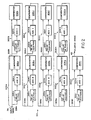
- a grayscale image processor 10 constructed in accordance with a preferred embodiment of the invention is illustrated in Figure 1, wherein data lines are illustrated as solid lines and control lines are indicated as broken lines.
- the processor 10 includes a processing unit 12, camera 14, monitor 16, and control computer 18.
- the camera 14 provides real images to both the processing unit 12 and the monitor 16.
- the unit 12 is capable of manipulating the real images inputted by the camera 14 to produce a variety of virtual images, or image transformations, useful in analyzing the real image.
- the monitor 16 selectively displays either the real image observed by the camera 14 or a virtual image produced by the processing unit 12.
- the computer 18 provides appropriate control signals to the various elements of the unit 12 to manipulate or transform the grayscale images according to an algorithm to produce a desired virtual image usable for feature extraction or other images information.
- the camera 14 provides a standard RS170 signal on an output line 20.
- This analogue composite video signal is transmitted over the line 20 at a rate of 30 frames per second with 480 horizontal scan lines per frame.
- An analogue digital converter 22 converts the analogue serial signal received on the line 20 to a serial digital signal outputted on a bus 23 to the processing unit 12.
- the converter 22 can convert a digital signal received on the bus 23 from the unit 12 to an analogue signal on the line 24 - to be displayed on the monitor 16.
- the analogue signal on the line 20 from the camera 14 can be passed directly to the monitor 16 via the line 24.
- the digital signal on the eight-line bus 23 includes one eight-bit word for each pixel in the video image.
- the analogue signal is digitized into 512 pixels per line on each of the 480 scan lines. Therefore, the processed image is made up of a matrix of lattice points or pixels.
- the eight-bit word corresponding to a pixel is given a value between 1 and 255 inclusive depending upon the intensity of the analogue signal (light intensity) of the pixel.
- the value 0 corresponds to total lack of intensity (i.e., darkness), while the value 255 corresponds to maximum intensity.
- the serialized digital representation passing over the bus 23 is eight bits wide and includes on eight-bit word for each pixel in the grayscale image.
- the processing unit 12 includes a frame buffer memory 26, an arithmetic logic unit (ALU) 28, a geometric logic unit (GLU) 30, and a count /locate unit (CLU) 32. All data buses interconnecting the elements of the processing unit 12 are eight bits wide enabling the serial signal to be transmitted over any one of the data lines.
- a pair of buses 34 and 36 interconnect the frame buffer memory 26 and the ALU 28; a bus 38 interconnects the ALU and the GLU 30, a bus 40 interconnects the GLU 30 and the CLU 32; and a bus 42 interconnects the CLU 32 and the frame buffer memory 26.
- the serial signal streams are outputted on the buses 34 and 36 to the ALU 28 which produces a single serial signal which then passes sequentially through the GLU 30 and the CLU 32 to return to the frame buffer 26.
- the frame buffer memory 26 comprises three 512 by 512 by 8-bit storage devices enabling three separate digital images to be stored simultaneously therein.
- the frame buffer 26 comprises three Model FB512 storage devices, manufactured by Imaging Technologies of Wolburn, Massachusetts.
- the arithmetic logic unit (ALU) 28 is a point or pixel processor, meaning that operations are carried out on the input image or images on a pixel-by-pixel basis to create an output image.
- the buses 34 and 36 convey one or two digital images from the memory 26 to the ALU 28 for processing.
- the digital image created by the ALU 28 is outputted on the bus 38 to the GLU 30.
- the arithmetic functions which the ALU 28 is capable of performing include, for example, passing an image, adding two images, subtracting two images, multiplying two images, dividing two images, ANDing two images, ORing two images, or complementing an image.
- the ALU 28 is a Model ALU512 logic unit manufactured by Imaging Technologies of Wolburn, Massachusetts.
- the geometric logic unit (GLU) 30 is coupled to the ALU 28 by the bus 38 and to count/locate unit 32 by the bus 40.
- the GLU 30 is more clearly illustrated in Figure 2, to be discussed below. Suffice it to say at this point that the bus 38 serially applies a digital image from the ALU 28 to the GLU 30 for processing.
- the digital image created by the GLU 30 is outputted on the bus 40 to the CLU 32.
- the count/locate unit (CLU) 32 is connected by buses 40 and 42 to the GLU 30 and the frame buffer 26, respectively.
- One or two functions can be performed by the CLU 32 as the serial signal stream passes therethrough.
- the CLU 32 does not affect the values of the serial signal stream in either function.
- the CLU 32 can output on the control bus 44 the coordinates of pixels within a given grayscale range.
- the CLU 32 can provide on the bus 44 a frequency count or histogram of pixels within a given grayscale range. the output coordinates and the histogram information are utilized by the computer 18 in further control of the processing unit 12.
- the digital image exiting the CLU 32 on the bus 42 is identical to the image entering the CLU on the bus 40.
- Control compute 18 which is coupled to the A/D converter 22, the frame buffer 26, the ALU 28, the GLU 30, and the CL U 32 through a multibus 44.
- Control signals are issued by the computer 18 over the multibus 44 during each vertical retrace of the camera 14 to the condition processor 10 for a possible imaging operation during the next frame period of the camera.
- the serial signal is routed sequentially through the ALU 28, the GLU 30, and the CLU 32 to return to the frame buffer 26.
- Each loop through the elements of the processing unit 12 can be performed once and only once during each frame period to produce one digital image to be stored in the memory 26.
- Each frame or image contains approximately a quarter of a million (250,000) pixels.
- the ALU 28, the GLU 30, and the CLU 32 all operate at a speed of approximately ten megahertz to process one entire digital image during approximately one frame cycle and leave sufficient time for the control computer 18 to reprogram the units for operation during the next frame cycle.
- the computer 18 comprises a MOTOROLA 68000 microcomputer having 512K of memory.
- a disc 46 is conventionally coupled through a bus 48 to the computer 18 to provide the requisite storage for the computer.
- a terminal 50 including a keyboard is conventionally coupled through a bus 52 to the computer 18 to provide a means of communicating command signals to the control computer.
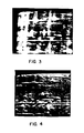
- Figure 3 is a real image of a laboratory sample of human blood proteins distributed within a two-dimensional electrophoretic g el .
- the light intensity of each pixel throughout the image is proportional to the density of proteins at the pixel. Proteins disperse vertically according to their molecular weight and disperse horizontally according to their molecular charge.
- the means for producing such a laboratory sample is generally well known.
- Specimens such as disclosed in Figure 3 are analyzed to determine the position and amount of each protein within the sample. By locating the position of the proteins, one can determine the types of proteins present. By determining the intensity of the image at each location, one can determine the amount of proteins present. Image processing is desired which will reveal the intensity and location of the local protein spots.
- the Figure 4 virtual image appears to be a three-dimensional surface wherein the apparent height of the surface at each pixel corresponds to the light intensity of the Figure 3 real image at each pixel.
- the Figure 4 surface appears to be illuminated by a light source located an infinite distance from the upper right corner.
- the production of the Figure 4 virtual image is generally well known to those having skill in the art of computer graphics and does not comprise the subject matter of the present application.
- Figure 4 is provided herein simply as an alternative conceptualization of the grayscale image of Figure 3.
- FIG. 37 illustrates the opening of a grayscale image 90 by a spherical structuring element 92.
- the height of the image surface 90 corresponds to the light intensity.
- the opening of the image by the element 92 is the locus of points covered by the spherical element wherever the element is tangential to and below the image surface.
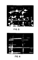
- Figure 5 is a virtual image which is the result of subtracting the opening of the Figure 3 real image from the Figure 3 real image.
- the opening of the Figure 3 real image is by a spherical structuring element having a diameter larger than the largest protein spot.
- the opening of the Figure 3 image by the spherical structuring element removes the spots and the streaks in the Figure 3 image because the spherical structuring element is "too large” to fit in the spots or streaks.
- Subtracting the opening from the original image removes the non-homongeeous background of the image (i.e., variation in background intensity) due to uneven lighting of the real image and/or smearing of the protein in the electrophoresis process.
- Figure 6 is a grayscale virtual image which comprises the union of two openings--the first using a vertical bar structuring element longer than the widest spot and the second using a horizontal bar structuring element longer than the widest spot.
- the Figure 6 image illustrates the streaks in the electropheretic specimen which should be removed prior to locating the protein deposits.
- Figure 7 is a virtual image produced by subtracting the Figure 6 virtual image from the Figure 5 virtual image. Consequentially, both the non-homongeeous background and the streaking of the real image of Figure 3 are removed.
- the virtual image of Figure 7 is therefore relatively "clean" and includes only blood protein deposits and can be more critically analyzed than the real image of Figure 3.
- Sample analysis is completed by locating the local maxima of the Figure 7 image and determining the height or intensity of the local maxima using the CLU 32.
- grayscale manipulation provides a relatively wide range of image analysis.
- Grayscale image transformations can be conceptually broken down into binary transformations by considering the umbra representation of a grayscale image.
- Figure 8 illustrates an intensity function 100 of a grayscale image along a single scan line. Distance along the horizontal axes corresponds to distance along the horizontal scan line; while distance along the vertical axes corresponds to the intensity or brightness of the grayscale image at the corresponding position on the scan line.
- the intensity function 100 includes two relatively dark portions 102 and 104, a relatively narrow bright spot 106, and a relatively wide brighter area 108.
- An umbra 110 of the intensity function 100 is illustrated in Figure 9.
- the umbra of an intensity function is the locus of points between the intensity function and minus infinity, inclusive of the intensity function. Consequently, the umbra 110 of the intensity function 100 is the crosshatched area under and including intensity function 100 in Figure 9.
- the umbra 110 of the intensity function 100 can be eroded by a circular structuring element 112 to produce an eroded intensity function 114 having an umbra l16 ( Figure 10).
- the eroded intensity function l14 can be dilated by the same circular structuring element 112 ( Figure 11) to produce an intensity function 118 and its associated umbra 120.
- the intensity function 118 is the opening of the intensity function 100, meaning that the intensity function 100 has been eroded and dilated by the identical structuring element, namely the disc 112.
- Figures 12-15 illustrate the concept of shifting a grayscale image.
- An intensity function 160 is illustrated in Figure 12 and includes a relatively bright area 162 and a relatively wide uniformly dark area 164.
- the intensity function 160 can be shifted along the scan line in a horizontal direction ( Figure 13) to produce a shifted intensity function 160' by delaying the serial signal stream by an appropriate number of pixel counts.
- the functions 160 and 160' have identical shapes.
- the intensity function 160 can be shifted in intensity to produce a new function 160" ( Figure 14) at the same scan line position by adding a constant value to function 160 at all points on the horizontal axis.
- the shape of function 160" is identical to the shape of function 160 although having a high value at each corresponding point along the scan line.
- the intensity function 160 can be shifted both along a scan line and in intensity by both delaying the signal stream and adding a constant value to each word in the signal stream to produce shifted intensity function 160 "' ( Figure 15).
- the intensity function 160 can be shifted vertically in the image one or more scan lines by delaying the signal stream a number of pixel counts corresponding to the length of the scan line.
- Figures 16-19 illustrate the concept of the union of two grayscale images.
- the intensity function 160 and its associated umbra 166 are illustrated in Figure 16; while the intensity function 170 and its associated umbra 176 are illustrated in Figure 17.
- the union (U) of two intensity function A(x) and B(x) is expressed as follows:
- the union of the intensity functions 160 and 170 is obtained through the steps disclosed in Figures 18 and 19.
- the intensity functions 160 and 170 and their associated umbrae 166 and 176, respectively, are superimposed to produce a union umbra 186 consisting of all points in Figure 18 which are crosshatched in either direction.
- the union intensity function 180 of the umbra 186 is illustrated in Figure 19 and corresponds to the defined union of the intensity functions 160 and 170.
- a euclidean circular, or disc-shaped, structuring element 130 (Figure 20) is a two-dimensional structuring element which can be digitally constructed through a series of image transformations of a single point 132 by repetitively shifting the point along vectors 134 and ORing the shifted and unshifted images (see the Sternberg binary processor).
- the structuring element 130 is an idealized digital version wherein each of vectors 134 is identical in length.
- Figure 21 illustrates the reorientation of vectors 134 such that each of their tails is located at the origin 136.
- the direction of the vectors 134 has been maintained in rearranging the vectors from Figure 20 to Figure 21.
- the terminal points of the vectors 134 lie along the semicircle 135 extending below the horizontal axis such that the vectors form a hemidisc.
- a three-dimensional euclidean spherical structuring element as might be used in grayscale image extension of Figure 21 and illustrates a set of idealized digital vectors 142 all having their tails oriented on the origin 148. The terminal ends of all the vectors 142 lie on a hemisphere 144 uniformly filled with the vectors.
- the spherical structuring element 140 is created by repetitively shifting a point along vectors 142 and ORing the shifted and unshifted images.
- Figures 8-11 illustrate that grayscale image transformations can be broken down into a series of binary, or non-grayscale, transformations.
- Figures 12-15 illustrate that grayscale images can be shifted horizontally and vertically in the image and can be shifted in intensity by appropriate time delays and adders.
- Figures 16-19 illustrate the union of two grayscale images.
- Figure 20-23 illustrate that a polar symmetric structuring element in two or three dimensions can be broken down into a plurality of suitable vector shifts and unions.
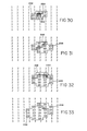
- Figures 25-36 are charts showing the grayscale values of the pixels in a grayscale image which is 9 pixels high by 9 pixels wide. Each location in each column and row corresponds to one pixel in the grayscale image. the number correspond to the grayscale intensities for the pixels. Although illustrated on a nine-by-nine image window, the image size is approximately one-quarter of a million pixels (i.e., 480 lines by 512 pixels).
- a grayscale structuring element 200 (Figure 25) includes nine central pixels 202 each having a grayscale value of five; sixteen surrounding pixels 204 configured to form the outline of a square and each having a grayscale value of four; and twelve edge pixels 206 each having a grayscale value three and arranged in four groups of three pixels centered on the sides of square 204.
- Figure 24 illustrated a three-dimensional structuring element 200' which corresponds to the digital grayscale structuring element 200 of Figure 25.
- the structuring element 200' ( Figure 24) includes a top portion 202' at a height of five units above the base of the structuring element, points along line 204' at a height of four units above the base, and points along the line 206' at a height of three units above the base.
- Other three-dimensional structuring elements which might be used include spheres, cones, bars, cylinders, paraboloids, and polyhedrons.
- Figure 26 illustrates the vector shifts required to construct structuring element 200.
- the solid three-dimensional structuring element 200' (Figure 24) is the dilation of a point along all of the Figure 26 vectors when each vector is considered to be the set of points lying on the line segment forming the body of the vector.
- the digital grayscale structuring element 200 (Figure 25) is the dilation of a point along all of the Figure 26 vectors when each vector is considered to be only the two extreme points of the line segments. All vectors in Figure 26 have their tails oriented at the origin 210.
- the nine shift vectors have the following three-dimensional coordinates from the origin: (0,-1,0), (1,-1,1), (1,0,0), (1,1,1), (0,1,0), (-1,1,1), (-1,0,0), (-1,-1,1), and (0,0,1).
- the first two coordinates of each vector specify shifts in the X and Y planes, while the third coordinate specifies a shift in a grayscale value.
- Figure 27 illustrates a single pixel 220 having a grayscale value of 101 to be dilated by the structuring element 200 of Figure 25.
- the virtual images depicted in Figures 28-36 correspond to the image transformations corresponding to each of the vector shifts depicted in Figure 26.
- the vector shifts are performed in the following order:
- the first vector shift is (0,-1,0).
- the first two coordinates specify a shift of one scan line upwardly, while the third coordinate specifies no shift in intensity. Consequently, original pixel 220 is delayed exactly one scan line to produce a pixel 222 ( Figure 28) having a grayscale value of 101 which is identical to the grayscale value of original pixel 220.
- the Figure 27 image is unioned with the shifted image such that pixel 224 corresponding to old pixel 220 acquires a grayscale value to 101 to complete the Figure 28 image.
- the second vector shift is (1,-1,1).
- the first two coordinates of the vector shift indicate that the image is to be shifted one pixel to the right and one scan line upwardly, while the third coordinate specifies that the grayscale values of all shifted pixels are to be increased by 1.
- the grayscale values of pixels 222 and 224 (Figure 28) are shifted to new pixels 226 in Figure 29 which have a grayscale value of 102.
- the background pixels which previously had a value of zero are increased to value one.
- the union of the image of Figure 28 with the new image changes to the value of the pixels 228 to 101 corresponding to pixels 222 and 224 in Figure 28.
- the third shift vector is (1,0,0).
- the first two coordinates designate a one-pixel shift to the right, while the third coordinate specifies no change in intensity.
- the pixels 226 and 228 of Figure 29 are therefore shifted to pixels 230 of Figure 30.
- the virtual image of Figure 29 is then unioned with the delayed image such that pixels 232 are introduced into the virtual image and the pixel 234 acquires the grayscale value 102.
- the pixels 232 Prior to the union of the delayed image with the virtual image of Figure 29, the pixels 232 have a grayscale value of 1 and the pixel 234 has a value of 101 (not shown).
- Stage 4 processing is illustrated in Figure 31 and corresponds to the shift vector (1,1,1).
- the first two coordinates specify a shift of one pixel to the right and one pixel down, while the third coordinate specifies that each pixel value in the shifted stream is to be increased by one. Consequently, the pixels 230 and 232 of Figure 30 are shifted to pixels 236 and each is increased in grayscale value by one. The intensity of the background pixels also increases by one to have a resultant value 2.
- the virtual image of Figure 30 is then unioned with the shifted pixels to modify the grayscale values of pixels 238.
- Processing for Stage 5 is illustrated in Figure 32 and corresponds to the vector (0,1,0).
- the first two coordinates call for a shift of one scan line down, while the third coordinate calls for no alteration of gray value intensity in the shifted pixels. Consequently, the pixels 236 and 238 of Figure 31 are shifted to pixels 240 in Figure 32.
- the background pixels maintain their grayscale value of two.
- the virtual image of Figure 31 is unioned with the shifted image to alter the grayscale value of pixel locations 242. Additionally, through the union, the grayscale value of the pixel 244.changes to 103.
- Stage 6 processing is depicted in Figure 33 and corresponds to shift vector (-1,1,1).
- the first two coordinates call for a shift left of one pixel and a shift down of one scan line, while the third coordinate indicates that the grayscale value of the shifted pixels is to be increased by one. Consequently, the pixels 240 and 242 of Figure 32 are shifted to pixels 246 of Figure 33. Additionally, the grayscale values of pixels 246 and the background pixels are each increased by one.
- the virtual image of Figure 32 is unioned with the shifted image so that the pixels 248 acquire modified grayscale values.
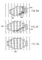
- Figure 34 illustrates the processing performed in the Stage 7 vector shift of (-1,0,0).
- the first two coordinates specify a shift of one pixel to the left, while the third coordinate indicates that the grayscale value of the shifted image is not to be changed. Therefore, pixels 246 and 248 of Figure 33 are shifted to pixels 250 in Figure 34.
- the background pixels maintain their grayscale value of three.
- the virtual image of Figure 33 is unioned with the shifted image such that the pixels 252 acquire modified grayscale values. Additionally, the grayscale values of pixels 254 within the pixel group 250 are increased to 104 corresponding to the pixel values in Figure 33.
- the Stage 8 processing is illustrated in Figure 35 and corresponds to shift vector (-1,1,1).
- the first two coordinates of the vector indicate that a shift of one pixel left and one scan line up is required, while the third coordinate indicates that all shifted grayscale pixel values are to be increased by one. Consequently, the pixels 250 and 252 are shifted to pixels 256, each of which is increased in grayscale value by one.
- the background pixels also increase in grayscale by one to have value four.
- the virtual image of Figure 34 is unioned with the shifted image to alter the grayscale value of pixels 258 to the corresponding values in Figure 34.
- Figure 36 illustrates the last or Stage 9 processing corresponding to the vector (0,0,1).
- the first two coordinates indicate that no shifting is to be performed, while the third coordinate indicates that all grayscale values are to be increased by one. Consequently, the pixels 256 and 258 of Figure 35 remain in the same position i.e., the pixels 260 in Figure 36; however, the grayscale value of the pixels 260 as well as the background pixels is increased by one.
- the background pixels therefore have a grayscale value of five, while each of the pixels 260 has a value one higher than the corresponding pixel in Figure 35.
- the virtual image of Figure 36 is the dilation of the image of Figure 27 containing a single nonzero pixel 220 by the structuring element illustrated in Figure 25.
- GLU Geometric Logic Unit
- the GLU 30 comprises a plurality of sequentially coupled function units 300 each of which includes a delay device 302, an adder 304, and a comparator 306.
- Each function unit 300 includes an input line 308 which delivers a serial signal both to the delay 302 and the comparator 306.
- the input signal stream delivered to the delay 302 is delayed by the indicated number of pixels and then inputted to the adder 304 which adds the indicated fixed or constant value to each word within the digital signal stream.
- This supplemented signal is then delivered to the comparator which logically combines the delayed and undelayed signals to produce an output signal delivered to the input line 308 of the next sequential function unit.
- the delays 302 and adders 304 are dynamically programmable under the control of the computer 18 (see Figure 1) to provide a desired delay and to add a desired fixed value to the pixel stream on each pass through the GLU.
- the values indicated within the blocks 302 and 304 are those required to perform the dilation depicted in Figures 27-36. All lines depicted in Figure 2 are eight-bit buses enabling the eight-bit serial words in the digitized stream to be passed in serial form.
- the input image to be dilated is delivered to the GLU 30 on the bus 38 ( Figure 2) and is conveyed over the lien 308a to both the delay 302a and the comparator 306a.
- this image corresponds to the real image depicted in Figure 27.
- This image is delayed one pixel by the delay 302a and the value 0 is added to each word in the delayed pixel stream at the adder 304a.
- the undelayed and delayed signals are then delivered to the comparator 306a which performs a logical function, or combination, of the serialized streams on a word-by-word basis.
- the comparator 306a selects the maximum of the undelayed and delayed stream in accordance with the above definition of union, which maximum is outputted on the line 308b to the second function unit 300b.
- the serial signal travelling over the line 308b corresponds to the image of Figure 28.
- the Figure 28 image is delayed to pixels by the delay 302b and each grayscale value of each word in the delayed stream is increased by 1 as it passed through the adder 304b.
- the undelayed and delayed signals are then applied to the comparator 306b which selects the maximum value for each pixel and outputs said value on the line 308c.
- the image passing over line 308c corresponds to the virtual image of Figure 29.
- the function units 300c, d, e, f, g, h, and i perform in a manner analogues to that described for the function units 300a and b.
- Each delay 302 provides the appropriate delay as et forth in the above chart under the column "Modified Delay”; and each adder 304 supplements each word of the delayed digitized stream by the value indicated under the column "Adder Value” in the above chart. Consequently, the images passing over the lines 308d, e, f, g, h, and i and bus 40 are the virtual images depicted in Figures 30-36, respectively.
- the dilated image of Figure 36 is outputted on the bus 40 and delivered to the CLU 32 (see Figure 1).
- the number of function units 300 in the GLU 30 depends in part upon the dilations performed. Although nine function units are illustrated in Figure 2, virtually any number can be used. Typically, a relatively large number (e.g., 27) will be provided, and the delays 302 and adders 304 of unused units on any particular pass will be set at 0.
- the present grayscale image processor 10 does not require separate specialized circuitry for eroding an image.
- the theorem utilized is that the erosion of the grayscale image by a structuring element is the dilation of the background , or complement, of the image by the structuring element reflected about the origin. Stated another way, the dilation of the background or complement of an image is equivalent to the erosion of an image when the structuring element is symmetric about the origin (polar symmetric).
- polar symmetric structuring elements such as a sphere
- the theorem may be stated as: the erosion of the image is the dilation of the background or complement of the image.
- the present processor is capable of eroding the image as well as dilating the image.
Abstract
A method and device for dilating a grayscale image by repetitively (a) delaying the serialized digital image (b) adding a constant value to each word (c) logically combining the delayed and undelayed serialized images on a word-by-word basis.
Description
- The present invention relates to image processing apparatus, systems and methods, and more particularly, to digital apparatus, systems and methods for processing grayscale images.
- A wide variety of image processing systems have been developed enabling digital computers to "see" or "read" an image. Typically, these image processors include a video camera, an analogue-to-digital converter for digitizing the video signal produced by the camera, and a digital device for processing the digitized information. For example, the image can be digitized into a matrix, or lattice, of pixels with each of 512 video scan lines divided into 512 pixels. In a non-grayscale image, each pixel can be encoded in a single bit which is set to zero if the pixel is dark and set to one if the pixel is illuminated. In a grayscale image, each pixel is encoded in a multi-bit word which is set to a value corresponding to the illumination intensity of the pixel. Grayscale images are of course more realistic and detailed than non-grayscale images. The image processors scan the digital images and process the digital information to interpret the image.
- One extremely efficient non-grayscale image processor is disclosed in European Patent Application No. 84308581.2 entitled DIGITAL IMAGE PROCESSING (hereinafter "the Sternberg binary processor"). This processor includes digital circuitry for effecting dilations and other transformations of serialized bit-wide streams representative of non-grayscale images. More specifically, the processor includes a plurality of sequentially coupled function units, each including a delay unit for delaying the serialized stream and a logic unit for performing any one of a plurality of logical operations on the delayed and undelayed streams. However, the Sternberg processor is capable of processing only bit-wide, or binary, data streams.
- Another image processor, less efficient than the Sternberg binary processor, routes a grayscale serial signal sequentially through several neighbourhood transformations to detect limited image features. Disclosures of this processor are provided in US-A-4,395,699, entitled METHOD AND APPARATUS FOR PATTERN RECOGNITION AND DETECTION and US-A-4,322,716, entitled METHOD AND APPARATUS FOR PATTERN RECOGNITION AND DETECTION. At each neighbourhood transformation stage, the "neighbourhood" of pixels surrounding a given pixel in one image is examined and the corresponding pixel in the new image is given a value which is a function of the neighbourhood pixels in the old image. All neighbourhood pixels in an image are made available for processing by serially routing the digital image through one or more shift registers. As the image is shifted through the registers, the appropriate register locations are simultaneously accessed to process a particular neighbourhood.
- This neighbourhood processorialso has drawbacks. First, the entire neighbourhood of a pixel must be made available and examined before the corresponding pixel in the new image can be given a value. This requires excessive delay and excessively complicated circuitry to make the neighbourhood pixels simultaneously available to drive the neighbourhood function generator. Second, the neighbourhood processing theory is an inefficient and cumbersome method of effecting many image transformations. Third, the neighbourhood theory greatly restricts the operations which can be performed, due to the limited size of the neighbourhood. Although in theory the neighbourhood could be enlarged, the hardware required to implement such a neighbourhood enlargement Would be even more expensive and/or complicated.
- It is an aim of the presentcinvention to attempt to alleviate the above problems. Essentially, a grayscale image processor and method are provided for effecting dilations and erosions of grayscale images at improved speeds and efficiences using simplified circuitry. More particularly, the image processor includes digital circuitry for performing a dilation of a grayscale digital image through a series of function units, each including a signal delay device, a signal supplementation device, and s signal recombination device. The function units are serially connected such that the output line of one unit is coupled to the input line of the subsequent unit. Each unit includes a delay device for delaying the input serial signal, an adder device for adding a fixed value to each word of the delayed signal, and a logic device for combining the undelayed input signal and the delayed supplemented signal to produce an output signal. By appropriately selecting the number of processing stages, the length of the delay at each stage, and the fixed value added to each word of the serial signal at each stage, the processor rapidly and efficiently performs grayscale image dilations and other image transformations using circuitry quite simplified over that known in the art.
- According to a first aspect of the invention a system for processing a grayscale image is characterised by serializing means for producing a first serial signal representative of the start image including a plurality of multi-bit words each corresponding to one of the points of the start image, means for producing an altered delayed serial signal comprising, positioned serially in either order, delay means for producing a delayed signal and adder means for adding a desired value to selected words, and operating means for selectively performing operations on the altered delayed serial signal and first signal to produce an output serial signal. Preferably the combining means comprises means for logically combining the selected ones of the delayed signals and the input signals; this may be on a word-by-word basis. The delaying means may comprise a programmable delay circuit for selectively delaying an input signal applied to said circuit; and the adder means may comprise a programmable adder for adding a selected value to the words in the delay signal.
- According to a second aspect a geometric logic unit is characterised by a plurality of serially coupled stages each comprising input port means for receiving an input serial signal means for producing an altered delayed serial signal dependent upon the input signal comprising, positioned serially in either order, delay means for selectively delaying the signal and adder means for adding a preselected value to each word of the signal, and means for selectively combining the altered delayed serial signal and the input signal to produce an output serial signal, and output port means for outputting the output serial signal.
- According to a third aspect, a method of manipulating a start serial signal representative of a grayscale image is characterised by routing a signal representative of the start serial signal sequentially through one or more processing sequences each having an input signal and an output signal and producing an altered delayed signal from the input signal by delaying the input signal and then adding a constant value to each word in the delayed signal (or vice versa) and logically combining the input signal and the altered delayed signal to produce the output signal.
- According to another aspect, there is provided a method of manipulating at least one start serial signal each representative of a grayscale image including a matrix of pixels to produce at least one resultant serial signal each representative of a processed image, each signal including a plurality of multi-bit serial words, each word corresponding to a pixel and having a value indicative of the light intensity of the pixel, said method comprising routing said start signals sequentially through a plurality of processing sequences each comprising: supplying at least one input signal each to an input port; delaying at least one of the input signals to produce at least one delayed signal each corresponding to one of the input signals, said delaying step including adding a fixed value to each word of each signal delayed by said delaying step; and combining selected ones of the modified delayed signals and the input signals to produce at least one output serial signal. Alternatively, the adding step may precede the delaying step. Preferably the performing step comprises performing logical operations on one of the modified delayed signals and one of the input signals.
- According to another aspect there is provided a method of processing at least one grayscale image each made up of a matrix of points, said method comprising: serializing each matrix of points into an input serial signal including one multi-bit word corresponding to each point; shifting at least one of said input serial signals to produce a shifted serial signal, said shifting step including adding a selected value to each word shifted; and operating on selected ones of the input serial signals and the delayed serial signals to produce at least one output signal representative of an output grayscale image.
- According to yet another aspect there is provided a method of dilating a grayscale image made of a matrix of points, said method comprising: serializing said matrix of points into a first serial signal including a multi-bit word corresponding to each point, each of the words having a value indicative of the light intensity of the point; shifting the first serial signal to produce a shifted serial signal; adding a fixed value to each word of the signal shifted to produce a modified shifted signal; and combining the first serial signal and the modified shifted serial signal to produce a serial signal representative of a grayscale dilation of said image. Preferably the method comprises a plurality of step groups each comprising one of said shifting steps, one of said adding steps, and one of said combining steps; and wherein said method further comprises routing said first serialized signal sequentially through said plurality of step groups. Also, the shifting step may comprise delaying the serial signal inputted to the associated step group. The combining steps may comprise logically combining the signals inputted to and delayed by the associated step group. Finally, the logical combining step may comprise selecting the maximum of the signals inputted to and delayed by the associated step group.
- The present system and method are based on mathmatical morphology, the science of processing and analyzing digital images through set transformations. The dilation operation propagates pixel states representative of relatively high intensities throughout some region of a grayscale image. The inverse (dual) operation, erosion, contracts regions of relatively high grayscale intensity in an image. The transformations of mathematical morphology have previously been implemented for grayscale images as neighbourhood transformations. The present invention eliminates the need for neighbourhood transformations of grayscale images as a source of dilation and erosion transformations and thus eliminates the relatively complex circuitry required to make a neighbourhood of grayscale pixels accessible simultaneously. The processor is capable of dilating and eroding grayscale images at relatively rapid speeds using comparatively simple circuitry as compared with known processors. Thus, the present invention is both a simplification and an extension of the current methodology.
- The invention may be carried into practice in various ways and one system and method of grayscale image dilation and the hardware suitable to implement these will now be described, by way of example, with reference to the diagrams, in which:
- Figure 1 is a schematic diagram showing the grayscale image processor;
- Figure 2 is a detailed schematic diagram of the geometric logic unit (GLU) of the processor;
- Figure 3 is a grayscale real image of a laboratory specimen wherein human blood proteins are dispersed within an electrophoretic gel;
- - Figure 4 is a grayscale virtual image conceptually illustrating the umbra of the real image of Figure 3;
- Figure 5 is a virtual image showing the opening of the real image of Figure 3 by a spherical structuring element substracted from the real image of Figure 3;
- Figure 6 is a virtual image showing the union of the openings of the real image of Figure 3 by structuring elements comprising vertical and horizontal bars;
- Figure 7 is a virtual image showing the difference of the virtual images of Figure 5 and 6;
- Figure 8 is a diagram of the light intensity along one horizontal scan line of a grayscale image;
- Figure 9 is a diagram showing the umbra of the intensity function of Figure 8;
- Figure 10 is a diagram showing the erosion of the umbra of Figure 9 by a circular structuring element;
- Figure 11 is a diagram showing the dilation of the eroded umbra of Figure 10 by the same circular structuring element;
- Figure 12 is a diagram of the intensity function of another horizontal scan line of a grayscale image;
- Figure 13 is a diagram showing the intensity function of Figure 12 shifted only along the scan line;
- Figure 14 is a diagram showing the intensity function of Figure 12 shifted only in intensity;
- Figure 15 is a diagram showing the intensity function of Figure 12 shifted both along the scan line and in intensity;
- Figure 16 is a diagram showing the umbra of the intensity function of Figure 12;
- Figure 17 is a diagram showing the intensity function and corresponding umbra of yet another scan line of a grayscale image;
- Figure 18 is a diagram showing the umbrae of Figure 16 and 17 superimposed on one another;
- Figure 19 is a diagram showing the intensity function of the union of the umbrae of Figure 16 and 17;
- Figure 20 is a diagram of a euclidean circular structuring element;
- Figure 21 is a diagram showing exemplary shift vectors oriented at the origin for producing the structuring element of Figure 20;
- Figure 22 is an isometric view of a euclidean spherical structuring element;
- Figure 23 is a diagram showing exemplary shift vectors oriented at the origin for producing the structuring element of Figure 22;
- Figure 24 is an isometric view of a grayscale structuring element;
- Figure 25 is a chart showing the grayscale intensities of the pixels of the structuring element of Figure 24;
- Figure 26 is an oblique view showing the shift vectors (reoriented at the origin) required to produce the structuring element of Figure 24;
- Figure 27 is a chart showing a single illuminated pixel to be dilated by the Figure 24 structuring element;
- Figures 28-36 are charts showing virtual images corresponding to the Figure 25 image at the various stages in the geometric logic unit; and
- Figure 37 conceptually shows the opening of a grayscale image by a spherical structuring element.
- A
grayscale image processor 10 constructed in accordance with a preferred embodiment of the invention is illustrated in Figure 1, wherein data lines are illustrated as solid lines and control lines are indicated as broken lines. Theprocessor 10 includes a processing unit 12,camera 14, monitor 16, and controlcomputer 18. Thecamera 14 provides real images to both the processing unit 12 and themonitor 16. The unit 12 is capable of manipulating the real images inputted by thecamera 14 to produce a variety of virtual images, or image transformations, useful in analyzing the real image. Themonitor 16 selectively displays either the real image observed by thecamera 14 or a virtual image produced by the processing unit 12. Thecomputer 18 provides appropriate control signals to the various elements of the unit 12 to manipulate or transform the grayscale images according to an algorithm to produce a desired virtual image usable for feature extraction or other images information. - The
camera 14 provides a standard RS170 signal on anoutput line 20. This analogue composite video signal is transmitted over theline 20 at a rate of 30 frames per second with 480 horizontal scan lines per frame. An analoguedigital converter 22 converts the analogue serial signal received on theline 20 to a serial digital signal outputted on abus 23 to the processing unit 12. Similarly, theconverter 22 can convert a digital signal received on thebus 23 from the unit 12 to an analogue signal on theline 24-to be displayed on themonitor 16. Alternatively, the analogue signal on theline 20 from thecamera 14 can be passed directly to themonitor 16 via theline 24. - The digital signal on the eight-
line bus 23 includes one eight-bit word for each pixel in the video image. The analogue signal is digitized into 512 pixels per line on each of the 480 scan lines. Therefore, the processed image is made up of a matrix of lattice points or pixels. The eight-bit word corresponding to a pixel is given a value between 1 and 255 inclusive depending upon the intensity of the analogue signal (light intensity) of the pixel. Thevalue 0 corresponds to total lack of intensity (i.e., darkness), while the value 255 corresponds to maximum intensity. The serialized digital representation passing over thebus 23 is eight bits wide and includes on eight-bit word for each pixel in the grayscale image. - The processing unit 12 includes a
frame buffer memory 26, an arithmetic logic unit (ALU) 28, a geometric logic unit (GLU) 30, and a count /locate unit (CLU) 32. All data buses interconnecting the elements of the processing unit 12 are eight bits wide enabling the serial signal to be transmitted over any one of the data lines. A pair ofbuses frame buffer memory 26 and theALU 28; abus 38 interconnects the ALU and theGLU 30, abus 40 interconnects theGLU 30 and theCLU 32; and abus 42 interconnects theCLU 32 and theframe buffer memory 26. When one or two digital representations in theframe buffer 26 are to be processed, the serial signal streams are outputted on thebuses ALU 28 which produces a single serial signal which then passes sequentially through theGLU 30 and theCLU 32 to return to theframe buffer 26. - The
frame buffer memory 26 comprises three 512 by 512 by 8-bit storage devices enabling three separate digital images to be stored simultaneously therein. In the preferred embodiment, theframe buffer 26 comprises three Model FB512 storage devices, manufactured by Imaging Technologies of Wolburn, Massachusetts. - The arithmetic logic unit (ALU) 28 is a point or pixel processor, meaning that operations are carried out on the input image or images on a pixel-by-pixel basis to create an output image. The
buses memory 26 to theALU 28 for processing. The digital image created by theALU 28 is outputted on thebus 38 to theGLU 30. The arithmetic functions which theALU 28 is capable of performing include, for example, passing an image, adding two images, subtracting two images, multiplying two images, dividing two images, ANDing two images, ORing two images, or complementing an image. In the preferred embodiment theALU 28 is a Model ALU512 logic unit manufactured by Imaging Technologies of Wolburn, Massachusetts. - The geometric logic unit (GLU) 30 is coupled to the
ALU 28 by thebus 38 and to count/locateunit 32 by thebus 40. theGLU 30 is more clearly illustrated in Figure 2, to be discussed below. Suffice it to say at this point that thebus 38 serially applies a digital image from theALU 28 to theGLU 30 for processing. The digital image created by theGLU 30 is outputted on thebus 40 to theCLU 32. - The count/locate unit (CLU) 32 is connected by
buses GLU 30 and theframe buffer 26, respectively. One or two functions can be performed by theCLU 32 as the serial signal stream passes therethrough. TheCLU 32 does not affect the values of the serial signal stream in either function. First, theCLU 32 can output on thecontrol bus 44 the coordinates of pixels within a given grayscale range. Second, theCLU 32 can provide on the bus 44 a frequency count or histogram of pixels within a given grayscale range. the output coordinates and the histogram information are utilized by thecomputer 18 in further control of the processing unit 12. The digital image exiting theCLU 32 on thebus 42 is identical to the image entering the CLU on thebus 40. - Overall system control is provided by the
control compute 18, which is coupled to the A/D converter 22, theframe buffer 26, theALU 28, theGLU 30, and the CLU 32 through amultibus 44. Control signals are issued by thecomputer 18 over the multibus 44 during each vertical retrace of thecamera 14 to thecondition processor 10 for a possible imaging operation during the next frame period of the camera. Whenever a digital image is processed, the serial signal is routed sequentially through theALU 28, theGLU 30, and theCLU 32 to return to theframe buffer 26. Each loop through the elements of the processing unit 12 can be performed once and only once during each frame period to produce one digital image to be stored in thememory 26. Each frame or image contains approximately a quarter of a million (250,000) pixels. TheALU 28, theGLU 30, and theCLU 32 all operate at a speed of approximately ten megahertz to process one entire digital image during approximately one frame cycle and leave sufficient time for thecontrol computer 18 to reprogram the units for operation during the next frame cycle. In the preferred embodiment, thecomputer 18 comprises a MOTOROLA 68000 microcomputer having 512K of memory. - A
disc 46 is conventionally coupled through abus 48 to thecomputer 18 to provide the requisite storage for the computer. A terminal 50 including a keyboard is conventionally coupled through abus 52 to thecomputer 18 to provide a means of communicating command signals to the control computer. - The utility of grayscale image processing is illustrated in Figures 3-7. Figure 3 is a real image of a laboratory sample of human blood proteins distributed within a two-dimensional electrophoretic gel. The light intensity of each pixel throughout the image is proportional to the density of proteins at the pixel. Proteins disperse vertically according to their molecular weight and disperse horizontally according to their molecular charge. The means for producing such a laboratory sample is generally well known.
- Specimens such as disclosed in Figure 3 are analyzed to determine the position and amount of each protein within the sample. By locating the position of the proteins, one can determine the types of proteins present. By determining the intensity of the image at each location, one can determine the amount of proteins present. Image processing is desired which will reveal the intensity and location of the local protein spots.
- The Figure 4 virtual image appears to be a three-dimensional surface wherein the apparent height of the surface at each pixel corresponds to the light intensity of the Figure 3 real image at each pixel. The Figure 4 surface appears to be illuminated by a light source located an infinite distance from the upper right corner. The production of the Figure 4 virtual image is generally well known to those having skill in the art of computer graphics and does not comprise the subject matter of the present application. Figure 4 is provided herein simply as an alternative conceptualization of the grayscale image of Figure 3.
- As is well known, the opening of an image by a structuring element is the result of two sequential operations--namely, erosion and dilation of the image by the same structuring element. These grayscale image transformations are generally well known to those having skill in the art. For example, Figure 37 illustrates the opening of a
grayscale image 90 by aspherical structuring element 92. The height of theimage surface 90 corresponds to the light intensity. The opening of the image by theelement 92 is the locus of points covered by the spherical element wherever the element is tangential to and below the image surface. - Figure 5 is a virtual image which is the result of subtracting the opening of the Figure 3 real image from the Figure 3 real image. the opening of the Figure 3 real image is by a spherical structuring element having a diameter larger than the largest protein spot. the opening of the Figure 3 image by the spherical structuring element removes the spots and the streaks in the Figure 3 image because the spherical structuring element is "too large" to fit in the spots or streaks. Subtracting the opening from the original image removes the non-homongeeous background of the image (i.e., variation in background intensity) due to uneven lighting of the real image and/or smearing of the protein in the electrophoresis process.
- Figure 6 is a grayscale virtual image which comprises the union of two openings--the first using a vertical bar structuring element longer than the widest spot and the second using a horizontal bar structuring element longer than the widest spot. The Figure 6 image illustrates the streaks in the electropheretic specimen which should be removed prior to locating the protein deposits.
- Finally, Figure 7 is a virtual image produced by subtracting the Figure 6 virtual image from the Figure 5 virtual image. Consequentially, both the non-homongeeous background and the streaking of the real image of Figure 3 are removed. The virtual image of Figure 7 is therefore relatively "clean" and includes only blood protein deposits and can be more critically analyzed than the real image of Figure 3. Sample analysis is completed by locating the local maxima of the Figure 7 image and determining the height or intensity of the local maxima using the
CLU 32. As will be readily appreciate by this rather brief review of grayscale mathmatical morphology, grayscale manipulation provides a relatively wide range of image analysis. - Grayscale image transformations can be conceptually broken down into binary transformations by considering the umbra representation of a grayscale image. Figure 8 illustrates an
intensity function 100 of a grayscale image along a single scan line. Distance along the horizontal axes corresponds to distance along the horizontal scan line; while distance along the vertical axes corresponds to the intensity or brightness of the grayscale image at the corresponding position on the scan line. For example, theintensity function 100 includes two relativelydark portions bright spot 106, and a relatively widebrighter area 108. Anumbra 110 of theintensity function 100 is illustrated in Figure 9. the umbra of an intensity function is the locus of points between the intensity function and minus infinity, inclusive of the intensity function. Consequently, theumbra 110 of theintensity function 100 is the crosshatched area under and includingintensity function 100 in Figure 9. - The
umbra 110 of theintensity function 100 can be eroded by acircular structuring element 112 to produce an erodedintensity function 114 having an umbra l16 (Figure 10). Similarly, the eroded intensity function l14 can be dilated by the same circular structuring element 112 (Figure 11) to produce anintensity function 118 and its associatedumbra 120. Theintensity function 118 is the opening of theintensity function 100, meaning that theintensity function 100 has been eroded and dilated by the identical structuring element, namely thedisc 112. - Figures 12-15 illustrate the concept of shifting a grayscale image. An
intensity function 160 is illustrated in Figure 12 and includes a relativelybright area 162 and a relatively wide uniformlydark area 164. Theintensity function 160 can be shifted along the scan line in a horizontal direction (Figure 13) to produce a shifted intensity function 160' by delaying the serial signal stream by an appropriate number of pixel counts. - The
functions 160 and 160' have identical shapes. Theintensity function 160 can be shifted in intensity to produce anew function 160" (Figure 14) at the same scan line position by adding a constant value to function 160 at all points on the horizontal axis. The shape offunction 160" is identical to the shape offunction 160 although having a high value at each corresponding point along the scan line. Finally, theintensity function 160 can be shifted both along a scan line and in intensity by both delaying the signal stream and adding a constant value to each word in the signal stream to produce shiftedintensity function 160 "' (Figure 15). Although not illustrated, theintensity function 160 can be shifted vertically in the image one or more scan lines by delaying the signal stream a number of pixel counts corresponding to the length of the scan line. - Figures 16-19 illustrate the concept of the union of two grayscale images. the
intensity function 160 and its associatedumbra 166 are illustrated in Figure 16; while theintensity function 170 and its associatedumbra 176 are illustrated in Figure 17. As has been previously defined in mathmatical morphology, the union (U) of two intensity function A(x) and B(x) is expressed as follows: -

umbrae union umbra 186 consisting of all points in Figure 18 which are crosshatched in either direction. Theunion intensity function 180 of theumbra 186 is illustrated in Figure 19 and corresponds to the defined union of the intensity functions 160 and 170. - A euclidean circular, or disc-shaped, structuring element 130 (Figure 20) is a two-dimensional structuring element which can be digitally constructed through a series of image transformations of a
single point 132 by repetitively shifting the point alongvectors 134 and ORing the shifted and unshifted images (see the Sternberg binary processor). Thestructuring element 130 is an idealized digital version wherein each ofvectors 134 is identical in length. - Figure 21 illustrates the reorientation of
vectors 134 such that each of their tails is located at theorigin 136. The direction of thevectors 134 has been maintained in rearranging the vectors from Figure 20 to Figure 21. The terminal points of thevectors 134 lie along the semicircle 135 extending below the horizontal axis such that the vectors form a hemidisc. - A three-dimensional euclidean spherical structuring element as might be used in grayscale image extension of Figure 21 and illustrates a set of idealized
digital vectors 142 all having their tails oriented on theorigin 148. The terminal ends of all thevectors 142 lie on ahemisphere 144 uniformly filled with the vectors. Thespherical structuring element 140 is created by repetitively shifting a point alongvectors 142 and ORing the shifted and unshifted images. - Summarizing, Figures 8-11 illustrate that grayscale image transformations can be broken down into a series of binary, or non-grayscale, transformations. Figures 12-15 illustrate that grayscale images can be shifted horizontally and vertically in the image and can be shifted in intensity by appropriate time delays and adders. Figures 16-19 illustrate the union of two grayscale images. Figure 20-23 illustrate that a polar symmetric structuring element in two or three dimensions can be broken down into a plurality of suitable vector shifts and unions.
- Figures 25-36 are charts showing the grayscale values of the pixels in a grayscale image which is 9 pixels high by 9 pixels wide. Each location in each column and row corresponds to one pixel in the grayscale image. the number correspond to the grayscale intensities for the pixels. Although illustrated on a nine-by-nine image window, the image size is approximately one-quarter of a million pixels (i.e., 480 lines by 512 pixels).
- A grayscale structuring element 200 (Figure 25) includes nine
central pixels 202 each having a grayscale value of five; sixteen surroundingpixels 204 configured to form the outline of a square and each having a grayscale value of four; and twelveedge pixels 206 each having a grayscale value three and arranged in four groups of three pixels centered on the sides ofsquare 204. - Figure 24 illustrated a three-dimensional structuring element 200' which corresponds to the digital
grayscale structuring element 200 of Figure 25. The structuring element 200' (Figure 24) includes a top portion 202' at a height of five units above the base of the structuring element, points along line 204' at a height of four units above the base, and points along the line 206' at a height of three units above the base. Other three-dimensional structuring elements which might be used include spheres, cones, bars, cylinders, paraboloids, and polyhedrons. - Figure 26 illustrates the vector shifts required to construct structuring
element 200. The solid three-dimensional structuring element 200' (Figure 24) is the dilation of a point along all of the Figure 26 vectors when each vector is considered to be the set of points lying on the line segment forming the body of the vector. The digital grayscale structuring element 200 (Figure 25) is the dilation of a point along all of the Figure 26 vectors when each vector is considered to be only the two extreme points of the line segments. All vectors in Figure 26 have their tails oriented at theorigin 210. The nine shift vectors have the following three-dimensional coordinates from the origin: (0,-1,0), (1,-1,1), (1,0,0), (1,1,1), (0,1,0), (-1,1,1), (-1,0,0), (-1,-1,1), and (0,0,1). The first two coordinates of each vector specify shifts in the X and Y planes, while the third coordinate specifies a shift in a grayscale value. - Figure 27 illustrates a
single pixel 220 having a grayscale value of 101 to be dilated by thestructuring element 200 of Figure 25. The virtual images depicted in Figures 28-36 correspond to the image transformations corresponding to each of the vector shifts depicted in Figure 26. The vector shifts are performed in the following order:
- The first vector shift is (0,-1,0). The first two coordinates specify a shift of one scan line upwardly, while the third coordinate specifies no shift in intensity. Consequently,
original pixel 220 is delayed exactly one scan line to produce a pixel 222 (Figure 28) having a grayscale value of 101 which is identical to the grayscale value oforiginal pixel 220. The Figure 27 image is unioned with the shifted image such that pixel 224 corresponding toold pixel 220 acquires a grayscale value to 101 to complete the Figure 28 image. - The second vector shift is (1,-1,1). The first two coordinates of the vector shift indicate that the image is to be shifted one pixel to the right and one scan line upwardly, while the third coordinate specifies that the grayscale values of all shifted pixels are to be increased by 1. The grayscale values of
pixels 222 and 224 (Figure 28) are shifted tonew pixels 226 in Figure 29 which have a grayscale value of 102. The background pixels which previously had a value of zero are increased to value one. The union of the image of Figure 28 with the new image changes to the value of thepixels 228 to 101 corresponding topixels 222 and 224 in Figure 28. - The third shift vector is (1,0,0). The first two coordinates designate a one-pixel shift to the right, while the third coordinate specifies no change in intensity. The
pixels pixels 230 of Figure 30. The virtual image of Figure 29 is then unioned with the delayed image such thatpixels 232 are introduced into the virtual image and the pixel 234 acquires thegrayscale value 102. Prior to the union of the delayed image with the virtual image of Figure 29, thepixels 232 have a grayscale value of 1 and the pixel 234 has a value of 101 (not shown). -
Stage 4 processing is illustrated in Figure 31 and corresponds to the shift vector (1,1,1). The first two coordinates specify a shift of one pixel to the right and one pixel down, while the third coordinate specifies that each pixel value in the shifted stream is to be increased by one. Consequently, thepixels resultant value 2. The virtual image of Figure 30 is then unioned with the shifted pixels to modify the grayscale values ofpixels 238. - Processing for
Stage 5 is illustrated in Figure 32 and corresponds to the vector (0,1,0). The first two coordinates call for a shift of one scan line down, while the third coordinate calls for no alteration of gray value intensity in the shifted pixels. Consequently, thepixels 236 and 238 of Figure 31 are shifted topixels 240 in Figure 32. The background pixels maintain their grayscale value of two. The virtual image of Figure 31 is unioned with the shifted image to alter the grayscale value ofpixel locations 242. Additionally, through the union, the grayscale value of the pixel 244.changes to 103. - Stage 6 processing is depicted in Figure 33 and corresponds to shift vector (-1,1,1). The first two coordinates call for a shift left of one pixel and a shift down of one scan line, while the third coordinate indicates that the grayscale value of the shifted pixels is to be increased by one. Consequently, the
pixels pixels 246 of Figure 33. Additionally, the grayscale values ofpixels 246 and the background pixels are each increased by one. The virtual image of Figure 32 is unioned with the shifted image so that the pixels 248 acquire modified grayscale values. - Figure 34 illustrates the processing performed in the Stage 7 vector shift of (-1,0,0). The first two coordinates specify a shift of one pixel to the left, while the third coordinate indicates that the grayscale value of the shifted image is not to be changed. Therefore,
pixels 246 and 248 of Figure 33 are shifted topixels 250 in Figure 34. The background pixels maintain their grayscale value of three. the virtual image of Figure 33 is unioned with the shifted image such that the pixels 252 acquire modified grayscale values. Additionally, the grayscale values ofpixels 254 within thepixel group 250 are increased to 104 corresponding to the pixel values in Figure 33. - The Stage 8 processing is illustrated in Figure 35 and corresponds to shift vector (-1,1,1). The first two coordinates of the vector indicate that a shift of one pixel left and one scan line up is required, while the third coordinate indicates that all shifted grayscale pixel values are to be increased by one. Consequently, the
pixels 250 and 252 are shifted topixels 256, each of which is increased in grayscale value by one. The background pixels also increase in grayscale by one to have value four. The virtual image of Figure 34 is unioned with the shifted image to alter the grayscale value ofpixels 258 to the corresponding values in Figure 34. - Figure 36 illustrates the last or Stage 9 processing corresponding to the vector (0,0,1). The first two coordinates indicate that no shifting is to be performed, while the third coordinate indicates that all grayscale values are to be increased by one. Consequently, the
pixels pixels 260 in Figure 36; however, the grayscale value of thepixels 260 as well as the background pixels is increased by one. The background pixels therefore have a grayscale value of five, while each of thepixels 260 has a value one higher than the corresponding pixel in Figure 35. The virtual image of Figure 36 is the dilation of the image of Figure 27 containing a singlenonzero pixel 220 by the structuring element illustrated in Figure 25. - The structure for implementing the dilation depicted in Figures 27-36 is illustrated in Figure 2. The
GLU 30 comprises a plurality of sequentially coupledfunction units 300 each of which includes adelay device 302, anadder 304, and acomparator 306. Eachfunction unit 300 includes aninput line 308 which delivers a serial signal both to thedelay 302 and thecomparator 306. The input signal stream delivered to thedelay 302 is delayed by the indicated number of pixels and then inputted to theadder 304 which adds the indicated fixed or constant value to each word within the digital signal stream. This supplemented signal is then delivered to the comparator which logically combines the delayed and undelayed signals to produce an output signal delivered to theinput line 308 of the next sequential function unit. As illustrated, eachdelay 302 precedes the associatedadder 304; however, the system works equally well if eachadder 304 precedes the associateddelay 302. Thedelays 302 andadders 304 are dynamically programmable under the control of the computer 18 (see Figure 1) to provide a desired delay and to add a desired fixed value to the pixel stream on each pass through the GLU. The values indicated within theblocks - The delays and the fixed values to be added to the words of the delayed pixel streams are illustrated the following table:

- Many of the "desired delays" are negative. Consequently, a positive number corresponding to the negative number with largest magnitude in the "Desired Delay" column is added to all of the "-desired delay" values to produce the "modified delay" values. In the example, this value is 513 because the negative number of largest magnitude is -513 (Stage h)., Consequently, -512 becomes 1; -511 becomes 2; 1 becomes 514; and so forth. The "adder values" correspond to the third coordinate of the "shift vectors" and indicate the amount by which the grayscale value for each pixel in the delayed stream is to be increased. Each of the values under the column "Modified Delay" for each stage is applied to the
appropriate delay 302 such that the delay for that function unit provides the desired shift. Similarly, theadders 304 are programmed under the control of thecomputer 18 to add the value under the column "Adder Value" for the appropriate stage. - The input image to be dilated is delivered to the
GLU 30 on the bus 38 (Figure 2) and is conveyed over thelien 308a to both the delay 302a and the comparator 306a. In the present example, this image corresponds to the real image depicted in Figure 27. This image is delayed one pixel by the delay 302a and thevalue 0 is added to each word in the delayed pixel stream at the adder 304a. The undelayed and delayed signals are then delivered to the comparator 306a which performs a logical function, or combination, of the serialized streams on a word-by-word basis. In the preferred embodiment, the comparator 306a selects the maximum of the undelayed and delayed stream in accordance with the above definition of union, which maximum is outputted on theline 308b to thesecond function unit 300b. The serial signal travelling over theline 308b corresponds to the image of Figure 28. The Figure 28 image is delayed to pixels by the delay 302b and each grayscale value of each word in the delayed stream is increased by 1 as it passed through the adder 304b. The undelayed and delayed signals are then applied to thecomparator 306b which selects the maximum value for each pixel and outputs said value on theline 308c. The image passing overline 308c corresponds to the virtual image of Figure 29. - The function units 300c, d, e, f, g, h, and i perform in a manner analogues to that described for the function units 300a and b. Each
delay 302 provides the appropriate delay as et forth in the above chart under the column "Modified Delay"; and eachadder 304 supplements each word of the delayed digitized stream by the value indicated under the column "Adder Value" in the above chart. Consequently, the images passing over the lines 308d, e, f, g, h, and i andbus 40 are the virtual images depicted in Figures 30-36, respectively. The dilated image of Figure 36 is outputted on thebus 40 and delivered to the CLU 32 (see Figure 1). Because of the offset of 513 pixels used to alter all of the "desired delay" values to "modified delay" values, appropriate panning and scrolling must be performed in software as the image is stored in theframe buffer 26 to return the image to the proper screen position. In the case of thevalue 513, this means shifting the image up one scan line and left one pixel prior to storage. - The number of
function units 300 in theGLU 30 depends in part upon the dilations performed. Although nine function units are illustrated in Figure 2, virtually any number can be used. Typically, a relatively large number (e.g., 27) will be provided, and thedelays 302 andadders 304 of unused units on any particular pass will be set at 0. - By taking advantage of one of the long-known theorms of mathmatical morphology, the present
grayscale image processor 10 does not require separate specialized circuitry for eroding an image. the theorem utilized is that the erosion of the grayscale image by a structuring element is the dilation of the background , or complement, of the image by the structuring element reflected about the origin. Stated another way, the dilation of the background or complement of an image is equivalent to the erosion of an image when the structuring element is symmetric about the origin (polar symmetric). When polar symmetric structuring elements (such as a sphere) are used, the theorem may be stated as: the erosion of the image is the dilation of the background or complement of the image. Therefore, when an image is to be eroded, the image is first complemented in theALU 28, dilated in theGLU 30, and then again complemented in theALU 28 on a second pass through the processor 12. Complement means taking the two's complement of each eight-bit word in the serial signal stream. Accordingly, the present processor is capable of eroding the image as well as dilating the image.
Claims (11)
1. A system (10) for processing a grayscale start image made up of a matrix of points, characterised by serializing means for producing a first serial signal representative of the start image, including a plurality of multi-bit words each correspondng to one of the points of the start image means (300) for producing an altered delayed serial signal comprising, positioned serially in either order, delay means (302) for producing a delayed signal and adder means (304) for adding a desired value to selected words, and operating means (306) for selectively performing operations on the altered delayed serial signal and the first signal to produce an output serial signal.
2. A system as claimed in Claim 1 in which the system is adapted to produce an output (being the output serial signal) which is representative of a grayscale dilation of the start image.
3. A system as claimed in Claim 1 in which the operating means (306) comprises means for performing logical operations on the altered delayed signal and the first signal.
4. A system as claimed in Claim 2 in which the operating means (306) comprises means for selecting the maximum of the altered delayed signal and the first signal.
5. A system comprising a plurality of systems (a, b, c, d, e, f, g, h, i) each as claimed in any of the preceding claims and further comprising means (18; 308) for routing the serial signal sequentially through the said plurality of systems.
6. A geometric logic unit (30) for processing a start serial signal representative of a grayscale image made up a matrix of points to produce a processed serial signal representative of a processed grayscale image, the geometric logic unit characterised by a plurality of serially coupled stages each comprising input port means (38) for receiving an input serial signal, means (300) for producing an altered delayed serial signal dependent upon the input signal comprising, positioned serially in either order, delay means (302) for selectively delaying the signal and adder means (304) for adding a preselected value to each word of the signal, and means (306) for selectively combining the altered delayed serial signal and the input signal to produce an output serial signal; and output port means for outputting the output serial signal.
7. A geometric unit as claimed in Claim 6 arranged to process a signal (being the start serial signal) including a plurality of multi-bit words each corresponding to one of the points of the grayscale image and having a value representative of the intensity of the said point, and arranged to produce a final output serial signal from the last of the coupled stages representative of the dilution of the grayscale image.
8. A geometric logic unit as claimed in any one of the preceeding claims in which the combining means (306) comprises means for selecting the maximum of the input signal and the altered delayed serial signal.
9. A method of manipulating a start serial signal representative of a grayscale image to produce an end serial signal representative of a dilation of the grayscale image, characterised by routing a signal representative of the start serial signal sequentially through one or more processing sequences each having an input signal and an output signal and including the steps of: producing an altered delayed signal from the input signal by delaying the input signal and then adding a constant value to each word in the delayed signal (or vice versa) and logically combining the input signal and the altered delayed signal to produce the output signal.
10. A method as claimed in Claim 9 in which each of the said combining actions comprises selecting the maximum of the input and the altered delayed signals on a word-by-word basis.
11. A method as claimed in Claim 9 or Claim 10 in which the start serial signal includes a multi-bit word corresponding to each point of the grayscale image, each of the words having a value indicative of the light intensity of the corresponding point.
Applications Claiming Priority (2)
| Application Number | Priority Date | Filing Date | Title |
|---|---|---|---|
| US06/644,101 US4641356A (en) | 1984-08-24 | 1984-08-24 | Apparatus and method for implementing dilation and erosion transformations in grayscale image processing |
| US644101 | 1984-08-24 |
Publications (1)
| Publication Number | Publication Date |
|---|---|
| EP0177160A2 true EP0177160A2 (en) | 1986-04-09 |
Family
ID=24583457
Family Applications (1)
| Application Number | Title | Priority Date | Filing Date |
|---|---|---|---|
| EP85306027A Withdrawn EP0177160A2 (en) | 1984-08-24 | 1985-08-23 | Apparatus and method for implementing dilation and erosion transformation in grayscale image processing |
Country Status (3)
| Country | Link |
|---|---|
| US (1) | US4641356A (en) |
| EP (1) | EP0177160A2 (en) |
| JP (1) | JPS61112284A (en) |
Cited By (1)
| Publication number | Priority date | Publication date | Assignee | Title |
|---|---|---|---|---|
| US4760607A (en) * | 1986-07-31 | 1988-07-26 | Machine Vision International Corporation | Apparatus and method for implementing transformations in grayscale image processing |
Families Citing this family (17)
| Publication number | Priority date | Publication date | Assignee | Title |
|---|---|---|---|---|
| FR2586120B1 (en) * | 1985-08-07 | 1987-12-04 | Armines | METHOD AND DEVICE FOR SEQUENTIAL IMAGE TRANSFORMATION |
| US4724543A (en) * | 1985-09-10 | 1988-02-09 | Beckman Research Institute, City Of Hope | Method and apparatus for automatic digital image analysis |
| JPS63104185A (en) * | 1986-10-22 | 1988-05-09 | Seiko Instr & Electronics Ltd | Circuit for enlarging and reducing conversion of picture |
| US5077677A (en) * | 1989-06-12 | 1991-12-31 | Westinghouse Electric Corp. | Probabilistic inference gate |
| FI90150C (en) * | 1991-05-14 | 1993-12-27 | Valtion Teknillinen | FILTER |
| US5710839A (en) * | 1994-04-20 | 1998-01-20 | Eastman Kodak Company | Method and apparatus for obscuring features of an image |
| US5848189A (en) * | 1996-03-25 | 1998-12-08 | Focus Automation Systems Inc. | Method, apparatus and system for verification of patterns |
| US5835638A (en) * | 1996-05-30 | 1998-11-10 | Xerox Corporation | Method and apparatus for comparing symbols extracted from binary images of text using topology preserved dilated representations of the symbols |
| US6192160B1 (en) * | 1996-09-19 | 2001-02-20 | Hyundai Microelectronics Co., Ltd. | Hardware architectures for image dilation and erosion operations |
| TW419634B (en) | 1999-02-02 | 2001-01-21 | Ind Tech Res Inst | Automatic detection system and method using bar code positioning |
| US6674914B1 (en) * | 1999-09-21 | 2004-01-06 | Lucent Technologies Inc. | Expandable grayscale morphological erosion operator |
| WO2002019698A2 (en) * | 2000-08-31 | 2002-03-07 | Rytec Corporation | Sensor and imaging system |
| US7961201B1 (en) | 2000-12-21 | 2011-06-14 | Cognex Corporation | Method and apparatus for producing graphical machine vision content for distribution via a network |
| US7962898B1 (en) | 2000-12-29 | 2011-06-14 | Cognex Corporation | Optimized distribution of machine vision processing |
| US7305114B2 (en) * | 2001-12-26 | 2007-12-04 | Cognex Technology And Investment Corporation | Human/machine interface for a machine vision sensor and method for installing and operating the same |
| AU2003270386A1 (en) * | 2002-09-06 | 2004-03-29 | Rytec Corporation | Signal intensity range transformation apparatus and method |
| US8150193B2 (en) * | 2009-01-13 | 2012-04-03 | Canon Kabushiki Kaisha | Generating an erosion image utilizing parallel pixel processing |
Family Cites Families (17)
| Publication number | Priority date | Publication date | Assignee | Title |
|---|---|---|---|---|
| US3214574A (en) * | 1952-07-16 | 1965-10-26 | Perkin Elmer Corp | Apparatus for counting bi-nucleate lymphocytes in blood |
| NL244109A (en) * | 1958-10-07 | |||
| DE1250166B (en) * | 1962-05-21 | 1967-09-14 | International Business Machines Corporation Armonk, NY (V St A) | Device for machine character recognition |
| US3573789A (en) * | 1968-12-13 | 1971-04-06 | Ibm | Method and apparatus for increasing image resolution |
| FR2092711A1 (en) * | 1970-06-10 | 1972-01-28 | Armines | |
| GB1401008A (en) * | 1971-08-17 | 1975-07-16 | Mullared Ltd | Character recognition apparatus |
| JPS48102926A (en) * | 1972-04-07 | 1973-12-24 | ||
| US4174514A (en) * | 1976-11-15 | 1979-11-13 | Environmental Research Institute Of Michigan | Parallel partitioned serial neighborhood processors |
| US4167728A (en) * | 1976-11-15 | 1979-09-11 | Environmental Research Institute Of Michigan | Automatic image processor |
| US4322716A (en) * | 1976-11-15 | 1982-03-30 | Environmental Research Institute Of Michigan | Method and apparatus for pattern recognition and detection |
| US4290049A (en) * | 1979-09-10 | 1981-09-15 | Environmental Research Institute Of Michigan | Dynamic data correction generator for an image analyzer system |
| US4301443A (en) * | 1979-09-10 | 1981-11-17 | Environmental Research Institute Of Michigan | Bit enable circuitry for an image analyzer system |
| US4395699A (en) * | 1979-09-10 | 1983-07-26 | Environmental Research Institute Of Michigan | Method and apparatus for pattern recognition and detection |
| US4369430A (en) * | 1980-05-19 | 1983-01-18 | Environmental Research Institute Of Michigan | Image analyzer with cyclical neighborhood processing pipeline |
| US4395697A (en) * | 1980-08-15 | 1983-07-26 | Environmental Research Institute Of Michigan | Off-image detection circuit for an image analyzer |
| US4395700A (en) * | 1980-08-15 | 1983-07-26 | Environmental Research Institute Of Michigan | Image analyzer with variable line storage |
| US4395698A (en) * | 1980-08-15 | 1983-07-26 | Environmental Research Institute Of Michigan | Neighborhood transformation logic circuitry for an image analyzer system |
-
1984
- 1984-08-24 US US06/644,101 patent/US4641356A/en not_active Expired - Fee Related
-
1985
- 1985-08-22 JP JP60183163A patent/JPS61112284A/en active Pending
- 1985-08-23 EP EP85306027A patent/EP0177160A2/en not_active Withdrawn
Cited By (1)
| Publication number | Priority date | Publication date | Assignee | Title |
|---|---|---|---|---|
| US4760607A (en) * | 1986-07-31 | 1988-07-26 | Machine Vision International Corporation | Apparatus and method for implementing transformations in grayscale image processing |
Also Published As
| Publication number | Publication date |
|---|---|
| US4641356A (en) | 1987-02-03 |
| JPS61112284A (en) | 1986-05-30 |
Similar Documents
| Publication | Publication Date | Title |
|---|---|---|
| US4641356A (en) | Apparatus and method for implementing dilation and erosion transformations in grayscale image processing | |
| US5432865A (en) | Method and apparatus for generating a plurality of parameters of an object in a field of view | |
| US4665554A (en) | Apparatus and method for implementing dilation and erosion transformations in digital image processing | |
| EP0628188B1 (en) | Method of identifying and characterizing a valid object by color | |
| EP0279297B1 (en) | Pattern contours in image processing | |
| US5448652A (en) | Adaptive display system | |
| US6762756B2 (en) | Graphics processor, system and method for generating screen pixels in raster order utilizing a single interpolator | |
| Kent et al. | PIPE (pipelined image-processing engine) | |
| US4395699A (en) | Method and apparatus for pattern recognition and detection | |
| US4665551A (en) | Apparatus and method for implementing transformations in digital image processing | |
| US4322716A (en) | Method and apparatus for pattern recognition and detection | |
| WO1984003784A1 (en) | Method of and apparatus for real-time high-speed inspection of objects for identifying or recognizing known and unknown portions thereof, including defects and the like | |
| EP0635151B1 (en) | Method of determining the interior points of an object in a background | |
| EP0069542B1 (en) | Data processing arrangement | |
| US4760607A (en) | Apparatus and method for implementing transformations in grayscale image processing | |
| US20060228007A1 (en) | Image processing | |
| JPH0222421B2 (en) | ||
| Elphinstone et al. | RAPAC: a high-speed image-processing system | |
| JP2628301B2 (en) | Video processing system | |
| JP2718728B2 (en) | 3D graphics processor | |
| Fritzsch et al. | Effective image processing using the special purpose processor GIPP | |
| White et al. | Algorithms and Architectures for Machine Vision | |
| GB2208708A (en) | Method and apparatus for generating a plurality of parameters of an object in a field of view | |
| JPH0571990B2 (en) | ||
| JPH06274617A (en) | Median filter processing method |
Legal Events
| Date | Code | Title | Description |
|---|---|---|---|
| PUAI | Public reference made under article 153(3) epc to a published international application that has entered the european phase |
Free format text: ORIGINAL CODE: 0009012 |
|
| AK | Designated contracting states |
Kind code of ref document: A2 Designated state(s): BE CH DE FR GB IT LI NL |
|
| STAA | Information on the status of an ep patent application or granted ep patent |
Free format text: STATUS: THE APPLICATION HAS BEEN WITHDRAWN |
|
| 18W | Application withdrawn |
Withdrawal date: 19881013 |
|
| RIN1 | Information on inventor provided before grant (corrected) |
Inventor name: STERNBERG, STANLEY RONALD |