EP0176935A2 - Rear view mirror for vehicles, in particular motor vehicles, with a back layer - Google Patents
Rear view mirror for vehicles, in particular motor vehicles, with a back layer Download PDFInfo
- Publication number
- EP0176935A2 EP0176935A2 EP85112110A EP85112110A EP0176935A2 EP 0176935 A2 EP0176935 A2 EP 0176935A2 EP 85112110 A EP85112110 A EP 85112110A EP 85112110 A EP85112110 A EP 85112110A EP 0176935 A2 EP0176935 A2 EP 0176935A2
- Authority
- EP
- European Patent Office
- Prior art keywords
- layer
- rearview mirror
- transparent
- metal
- additional
- Prior art date
- Legal status (The legal status is an assumption and is not a legal conclusion. Google has not performed a legal analysis and makes no representation as to the accuracy of the status listed.)
- Granted
Links
Images
Classifications
-
- G—PHYSICS
- G02—OPTICS
- G02B—OPTICAL ELEMENTS, SYSTEMS OR APPARATUS
- G02B5/00—Optical elements other than lenses
- G02B5/08—Mirrors
- G02B5/0816—Multilayer mirrors, i.e. having two or more reflecting layers
- G02B5/085—Multilayer mirrors, i.e. having two or more reflecting layers at least one of the reflecting layers comprising metal
- G02B5/0858—Multilayer mirrors, i.e. having two or more reflecting layers at least one of the reflecting layers comprising metal the reflecting layers comprising a single metallic layer with one or more dielectric layers
-
- B—PERFORMING OPERATIONS; TRANSPORTING
- B60—VEHICLES IN GENERAL
- B60R—VEHICLES, VEHICLE FITTINGS, OR VEHICLE PARTS, NOT OTHERWISE PROVIDED FOR
- B60R1/00—Optical viewing arrangements; Real-time viewing arrangements for drivers or passengers using optical image capturing systems, e.g. cameras or video systems specially adapted for use in or on vehicles
- B60R1/02—Rear-view mirror arrangements
- B60R1/08—Rear-view mirror arrangements involving special optical features, e.g. avoiding blind spots, e.g. convex mirrors; Side-by-side associations of rear-view and other mirrors
- B60R1/083—Anti-glare mirrors, e.g. "day-night" mirrors
-
- C—CHEMISTRY; METALLURGY
- C03—GLASS; MINERAL OR SLAG WOOL
- C03C—CHEMICAL COMPOSITION OF GLASSES, GLAZES OR VITREOUS ENAMELS; SURFACE TREATMENT OF GLASS; SURFACE TREATMENT OF FIBRES OR FILAMENTS MADE FROM GLASS, MINERALS OR SLAGS; JOINING GLASS TO GLASS OR OTHER MATERIALS
- C03C17/00—Surface treatment of glass, not in the form of fibres or filaments, by coating
- C03C17/34—Surface treatment of glass, not in the form of fibres or filaments, by coating with at least two coatings having different compositions
- C03C17/36—Surface treatment of glass, not in the form of fibres or filaments, by coating with at least two coatings having different compositions at least one coating being a metal
- C03C17/3602—Surface treatment of glass, not in the form of fibres or filaments, by coating with at least two coatings having different compositions at least one coating being a metal the metal being present as a layer
- C03C17/361—Coatings of the type glass/metal/inorganic compound/metal/inorganic compound/other
-
- C—CHEMISTRY; METALLURGY
- C03—GLASS; MINERAL OR SLAG WOOL
- C03C—CHEMICAL COMPOSITION OF GLASSES, GLAZES OR VITREOUS ENAMELS; SURFACE TREATMENT OF GLASS; SURFACE TREATMENT OF FIBRES OR FILAMENTS MADE FROM GLASS, MINERALS OR SLAGS; JOINING GLASS TO GLASS OR OTHER MATERIALS
- C03C17/00—Surface treatment of glass, not in the form of fibres or filaments, by coating
- C03C17/34—Surface treatment of glass, not in the form of fibres or filaments, by coating with at least two coatings having different compositions
- C03C17/36—Surface treatment of glass, not in the form of fibres or filaments, by coating with at least two coatings having different compositions at least one coating being a metal
- C03C17/3602—Surface treatment of glass, not in the form of fibres or filaments, by coating with at least two coatings having different compositions at least one coating being a metal the metal being present as a layer
- C03C17/3642—Surface treatment of glass, not in the form of fibres or filaments, by coating with at least two coatings having different compositions at least one coating being a metal the metal being present as a layer the multilayer coating containing a metal layer
-
- C—CHEMISTRY; METALLURGY
- C03—GLASS; MINERAL OR SLAG WOOL
- C03C—CHEMICAL COMPOSITION OF GLASSES, GLAZES OR VITREOUS ENAMELS; SURFACE TREATMENT OF GLASS; SURFACE TREATMENT OF FIBRES OR FILAMENTS MADE FROM GLASS, MINERALS OR SLAGS; JOINING GLASS TO GLASS OR OTHER MATERIALS
- C03C17/00—Surface treatment of glass, not in the form of fibres or filaments, by coating
- C03C17/34—Surface treatment of glass, not in the form of fibres or filaments, by coating with at least two coatings having different compositions
- C03C17/36—Surface treatment of glass, not in the form of fibres or filaments, by coating with at least two coatings having different compositions at least one coating being a metal
- C03C17/3602—Surface treatment of glass, not in the form of fibres or filaments, by coating with at least two coatings having different compositions at least one coating being a metal the metal being present as a layer
- C03C17/3657—Surface treatment of glass, not in the form of fibres or filaments, by coating with at least two coatings having different compositions at least one coating being a metal the metal being present as a layer the multilayer coating having optical properties
- C03C17/3663—Surface treatment of glass, not in the form of fibres or filaments, by coating with at least two coatings having different compositions at least one coating being a metal the metal being present as a layer the multilayer coating having optical properties specially adapted for use as mirrors
-
- G—PHYSICS
- G02—OPTICS
- G02B—OPTICAL ELEMENTS, SYSTEMS OR APPARATUS
- G02B5/00—Optical elements other than lenses
- G02B5/08—Mirrors
- G02B5/0816—Multilayer mirrors, i.e. having two or more reflecting layers
- G02B5/085—Multilayer mirrors, i.e. having two or more reflecting layers at least one of the reflecting layers comprising metal
- G02B5/0875—Multilayer mirrors, i.e. having two or more reflecting layers at least one of the reflecting layers comprising metal the reflecting layers comprising two or more metallic layers
-
- G—PHYSICS
- G02—OPTICS
- G02B—OPTICAL ELEMENTS, SYSTEMS OR APPARATUS
- G02B5/00—Optical elements other than lenses
- G02B5/20—Filters
- G02B5/26—Reflecting filters
Definitions
- the invention relates to a rear-view mirror for vehicles, in particular motor vehicles, or the like, with a transparent layer support, preferably consisting of sodium silicate glass, and a rear coating, which has a highly reflective mirror layer made of a metal or aluminum, and one arranged between the layer support and the mirror layer Has interference layer made of dielectric material.
- layers of the highly reflective metals silver and aluminum can be used as the rear coating for car mirrors, such a rear coating generally compared to a front one -coated rear-view mirror has the advantage that the Be - is coating by the mirror enclosure from direct atmospheric exposure, particularly pollution, protected.
- anti-glare rearview mirror is known (DE-A S 10 36 672; DE-AS 24 49 763), in which on the front of preferably made of glass transparent S chichtharis a lining in the form of a non-metallic, preferably metal oxide interference coating applied and the back side optionally is covered with a dark, absorbent coating.
- the interference coating may, for example, of three sub-layers in the order of high refractive index layer - low refractive index layer - made h ochêtde layer.
- Such a selectively reflecting blue coating creates a sufficiently bright image in daylight, while the glare effect from the headlights of the following vehicles with their high radiation component in the long-wave visible area is reduced when driving at night.
- a disadvantage of such a glare-free rearview mirror with front interference coating is, however, that the coating is directly exposed to the outside atmosphere.
- the coating can easily become scratched, which particularly disrupts the functioning of such a rearview mirror, because scratches on a highly reflective layer cause significantly stronger optical disturbances than, for example, on the interface of a normal glass pane to air with a reflectivity of only 4%.
- the invention is therefore based on the object of providing a glare-free rearview mirror for vehicles, in particular motor vehicles, which, while avoiding the disadvantages of the known rearview mirrors with front interference coating, has a light reflectance in the range between the minimum light reflectance of 0 required by the guidelines of the European Community , 4 and about 0.6.
- the dielectric interference layer ntaciousungstik in thickness than E is formed to the long-wave visible spectral range; and that an additional layer of a metal or metal alloy is arranged such thickness between the transparent substrate and the dielectric interference layer since the light transmittance ß the group consisting of the transparent substrate and the additive layer assembly by 10 to 55% lower than that of the transparent film carrier alone .
- a special embodiment of the invention provides that the light transmission of the composite consisting of the transparent layer support and the additional layer is 15 to 45% lower than that of the transparent layer support alone.
- the additional layer consists of chromium, nickel, iron, titanium, alloys of these metals or an alloy of the metals chromium, aluminum and iron.
- the invention also proposes that the additional layer consist of silver.
- the additional layer consists of aluminum.
- the coating of the transparent layer support for the production of the coating according to the invention is generally carried out as a whole by vacuum coating.
- the metal or metal alloy layers can erdampfervoriquesen by evaporation from resistively heated V or be applied by electron beam evaporation.
- Cathode sputtering is also suitable as direct current, low-frequency and high-frequency sputtering as well as the particularly economical method of MAGNETRON cathode sputtering.
- the dielectric interference layers can be made either by direct evaporation or sputtering of the corresponding dielectric materials.
- the known methods of reactive evaporation or reactive cathode sputtering of the corresponding metals can also be used.
- deposition processes such as e.g. B. wet chemical processes can be used by deposition from suitable starting solutions.
- silicate glass In addition to silicate glass, other transparent materials, preferably made of plastic, such as e.g. B. polymethyl methacrylates, polyesters, polycarbonates and the like can be used.
- plastic e.g. B. polymethyl methacrylates, polyesters, polycarbonates and the like.
- a protective layer to the coating to improve the corrosion resistance of the rearview mirror according to the invention.
- That can e.g. B. be a further metal, metal alloy layer or a metal oxide layer, which is applied in a vacuum process immediately after applying the actual selective coating, or a varnish coating. A combination of both measures is also planned.
- the light attenuation to be set by the additional layer in the range specified according to the invention depends on the light reflectance that is to be obtained for the glare-free rearview mirror.
- the required light attenuation by the additional layer is greater within the specified range, the lower the light reflectance is chosen.
- dielectric interference layer A large number of dielectric materials have proven to be suitable for the dielectric interference layer, provided that they are essentially absorption-free only in the visible region and thus do not cause additional undesired light attenuation.
- dielectric layers with a high refractive index> 1.7 suitable are used for the effective anti-reflective treatment of highly reflective metal single layers on their air side, such as Ti0 2 , ZnS, Ce0 2 , Bi 2 0 3 or Ta 2 O 5 , but also layers with a lower refractive index, e.g. B. silicon dioxide and magnesium fluoride.
- the dielectric interference layer fulfills a function as a spacing layer between the two metal layers, namely the reflection layer and the additional layer, its thickness corresponding to that of a quarter-wavelength layer for the long-wave visible region.
- the materials preferably used according to the invention for the additional layer namely chrome, nickel, iron, titanium, alloys of these metals or from an alloy of the metals chrome, aluminum and iron, are distinguished by good adhesion to the glass substrate and the subsequent dielectric when applied in vacuo Interference layer and thus convey a good overall layer
- layers of other metals and metal alloys are also suitable, for example also layers of the metals silver or aluminum used for the mirroring on the back.
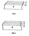
- Fig. 1 shows an embodiment of a rearview mirror according to the invention, in which an additional layer 12 made of chrome, then a dielectric anti-reflective layer 14 made of ZnS and then a reflective layer 15 made of silver are arranged on a transparent layer support 10 made of soda-silicate glass are.
- a protective layer 16 in this case a lacquer coating, is arranged after the reflection layer 15.
- the rearview mirror according to the invention can be produced in the manner described in the following examples:
- a chromium-nickel layer 12 with the composition 80% by weight of nickel and 20% by weight of chromium was first vapor-deposited on a clear glass pane 10 of 3 mm thickness in a high-vacuum evaporation system. The coating process was terminated when the light transmission of the pane, which was 91% before the start of vapor deposition, had dropped to 60%.
- a zinc sulfide layer 14 was then evaporated to a thickness of 65 nm.
- the coating with silver (reflective layer 15) was then carried out to such a thickness that the light transmission of the coated pane was below 1%.
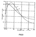
- the measurement of the spectral reflectance in the event of radiation incident from the glass side of the coated pane gave the course shown as curve 1 in FIG. 3.
- the result is the selective spectral required for glare-free vision course with decrease in the reflectance in the long-wave visible compared to the short-wave visible spectral range. Accordingly, the pane has a clear bluish cast when viewed from the glass side.
- the brightness level of the pane which has a light reflectance of 0.6, is at the upper limit of the desired range. With degrees of light reflection between 0.5 and 0.6, the double image effects in particular, which are caused by the slightly laterally offset additional reflection on the outside of the mirror, are no longer important.
- a chrome layer 12, a titanium dioxide layer 14 and an aluminum layer 15 were successively evaporated onto a clear glass pane 10 of 3 mm.
- the chrome layer 12 was of such a thickness that it reduced the light transmission of the uncoated pane from 91% to 76%.
- the thickness of the titanium dioxide layer 14 was 64 nm.
- the aluminum layer 15 was 64 nm.
- the coated pane like the pane in Example 1, also had a clear blue tint.
- the spectral reflection curve of the pane, measured from the glass side is shown as curve 2 in FIG. 3 and shows the desired selective reflection curve with decrease in the degree of reflection at longer wavelengths in the visible spectral range.
- the brightness level of this pane with a light reflectance of 0.54 is also in the desired middle range.
Abstract
Description
Die Erfindung betrifft einen Rückblickspiegel für Fahrzeuge, insbesondere Kraftfahrzeuge, oder dergleichen, mit einem transparenten Schichtträger, vorzugsweise aus Natron-Silikatglas bestehend, und einer rückseitigen Beschichtung, welche eine hochreflektierende Spiegelschicht aus einen Metall oder Aluminium, und eine zwischen dem Schichtträger und der Spiegelschicht angeordnete Interferenzschicht aus dielektrischem Material aufweist.The invention relates to a rear-view mirror for vehicles, in particular motor vehicles, or the like, with a transparent layer support, preferably consisting of sodium silicate glass, and a rear coating, which has a highly reflective mirror layer made of a metal or aluminum, and one arranged between the layer support and the mirror layer Has interference layer made of dielectric material.
Als rückseitige Beschichtung für Auto-Spiegel lassen sich bekanntlich Schichten der hochreflektierenden Metalle Silber und Aluminium einsetzen, wobei eine derartige rückseitige Beschichtung generell gegenüber einem vorderseitig beschichteten Rückblickspiegel den Vorteil hat, daß die Be- schichtung durch die Spiegeleinfassung gegen direkte atmosphärische Einwirkung, insbesondere Verschmutzung, geschützt ist. Mittels der vorgenannten hochreflektierenden Metalle erhält man Rückspiegel mit Reflexionswerten im sichtbaren Spektralbereich von mehr als 85%.As is known, layers of the highly reflective metals silver and aluminum can be used as the rear coating for car mirrors, such a rear coating generally compared to a front one -coated rear-view mirror has the advantage that the Be - is coating by the mirror enclosure from direct atmospheric exposure, particularly pollution, protected. By means of the above-mentioned highly reflective metals are obtained rearview mirror with R eflexionswerten in the visible spectral range of more than 85%.
Aus "Selective Optical Surfaces for Solar Energy Converters", von M.M. Koltun, New York, 1961, Seite 39, ist ein Spiegel des vorstehend beschriebenen Schichtaufbaus bekannt, bei dem zur weiteren Erhöhung des Reflexionsvermögens auf Ober 90 zwischen dem transparenten Schichtträger, im folgenden u.a. auch kurz als Glasträger bezeichnet, und der dort aus Aluminium bestehenden Metall-Reflexionsschicht eine reflexerhöhende, ein-oder zweilagige, dielektrische Interferenzschicht angeordnet ist.From "Selective Optical Surfaces for Solar Energy Converters", by M.M. Koltun, New York, 1961, page 39, a mirror of the layer structure described above is known, in which to further increase the reflectivity to upper 90 between the transparent substrate, in the following u.a. also referred to for short as a glass substrate, and a reflective enhancing, one or two-layer dielectric interference layer is arranged on the metal reflection layer made of aluminum there.
Derartige Spiegel führen jedoch aufgrund des bei Tageslicht durchaus erwünschten hohen (und im wesentlichen wellenlängenunabhängigen) Reflexionsgrades bei Nachtfahrten zur Blendung des Fahrers durch die Scheinwerfer nachfolgender Fahrzeuge.Such mirrors, however, lead to the driver being dazzled by the headlights of the following vehicles due to the high (and essentially wavelength-independent) degree of reflection that is desired in daylight when driving at night.
Andererseits sind blendfreie Rückblickspiegel bekannt (DE-AS 10 36 672; DE-AS 24 49 763), bei denen auf der Vorderseite des vorzugsweise aus Glas bestehenden transparenten Schichtträgers ein Belag in Form einer nichtmetallischen, vorzugsweise metalloxidischen Interferenzbeschichtung aufgebracht und die Rückseite gegebenenfalls mit einem dunklen, absorbierenden Überzug versehen ist. Die Interferenzbeschichtung kann dabei beispielsweise aus drei Teilschichten in der Reihenfolge hochbrechende Schicht - niedrigbrechende Schicht - hochbrechende Schicht bestehen. Werden die Dicken dieser Teilschichten als λ/4-Schichten auf das kurzwellige sichtbare Spektralgebiet eingestellt, so weisen derartige Spiegel im blauen Spektralbereich im Vergleich zum langwelligen Gelb-Rot-Bereich ein höheres Reflexionsvermögen auf. Durch einen solchermaßen selektiv reflektierenden Blaubelag wird bei Tageslicht noch ein ausreichend helles Bild erzeugt, während bei Nachtfahrten der Blendeffekt durch die Scheinwerfer nachfolgender Fahrzeuge mit ihrem hohen Strahlungsanteil im langwelligen sichtbaren Gebiet reduziert wird.On the other hand, anti-glare rearview mirror is known (DE-A S 10 36 672; DE-AS 24 49 763), in which on the front of preferably made of glass transparent S chichtträgers a lining in the form of a non-metallic, preferably metal oxide interference coating applied and the back side optionally is covered with a dark, absorbent coating. The interference coating may, for example, of three sub-layers in the order of high refractive index layer - low refractive index layer - made h ochbrechende layer. If the thicknesses of these sub-layers are set as λ / 4 layers to the short-wave visible spectral region, then such Mirrors in the blue spectral range have a higher reflectivity compared to the long-wave yellow-red range. Such a selectively reflecting blue coating creates a sufficiently bright image in daylight, while the glare effect from the headlights of the following vehicles with their high radiation component in the long-wave visible area is reduced when driving at night.
Ein Nachteil derartiger blendfreier Rückblickspiegel mit Vorderseiten-Interferenzbeschichtung besteht aber darin, daß die Beschichtung unmittelbar der Außenatmosphäre ausgesetzt ist. Insbesondere kann es bei Entfernung von Verschmutzungen von der beschichteten Vorderseite des Rückblickspiegels leicht zu Verkratzungen der Beschichtung kommen, welche die Funktionsweise eines derartigen Rückblickspiegels in besonderem Maße stören, weil Verkratzungen an einer hochreflektierenden Schicht wesentlich stärkere optische Störungen hervorrufen als beispielsweise an der Grenzfläche einer normalen Glasscheibe zu Luft mit einem Reflexionsvermögen von nur 4 %.A disadvantage of such a glare-free rearview mirror with front interference coating is, however, that the coating is directly exposed to the outside atmosphere. In particular, when dirt is removed from the coated front side of the rearview mirror, the coating can easily become scratched, which particularly disrupts the functioning of such a rearview mirror, because scratches on a highly reflective layer cause significantly stronger optical disturbances than, for example, on the interface of a normal glass pane to air with a reflectivity of only 4%.
Der Weg, durch rückseitige Anordnung der Beschichtung auf dem Schichtträger den notwendigen Schutz der Beschichtung zu erreichen, kann bei den vorgenannten nicht-metallischen Interferenzbeschichtungen nicht beschritten werden; sie sind transparent und müßten auf ihrer Rückseite durch einen dunklen Oberzug abgedeckt werden. Hierdurch würde jedoch die für die Wirkung des Interferenzfilters wichtige äußere Grenzfläche Interferenzbeschichtung/Luft ausgeschaltet, wodurch die Funktion des Filters störend beeinträchtigt würde.The way to achieve the necessary protection of the coating by arranging the coating on the back of the layer cannot be followed in the case of the aforementioned non-metallic interference coatings; they are transparent and should be covered on the back by a dark cover. However, this would switch off the external interference coating / air interface, which is important for the effect of the interference filter, which would impair the function of the filter.
Versucht man andererseits bei einem gattungsgemäßen Spiegel mit rückseitiger Reflexionsschicht aus Aluminium oder aber auch Silber sowie zwischen Schichtträger und Reflexionsschicht angeordneter dielektrischer Interferenzschicht die vorstehend beschriebene Selektivität in der Reflexion dadurch zu erzielen, daß die Interferenzschicht als auf das langwellige, sichtbare Gebiet angepaßte hochbrechende Ent- spiegelungsschicht, beispielsweise aus TiO2, CeO2, Ta2O5, Bi2O3 und/oder ZnS, ausgebildet wird, so führt dies zu einem allenfalls schwach blaustichigen Spiegel ohne nennenswerte Blendschutzwirkung.If one tries the other hand, in a generic mirror with a rear reflective layer of aluminum, or also silver and between substrate and reflective layer arranged dielectric interference layer, the selectivity described above in reflection to achieve the fact that the interference layer as nt to the l angwellige visible area adapted high refractive E - s is 3 an d / or ZnS, formed gelungsschicht pi e, for example, TiO 2, CeO 2, Ta 2 O 5, Bi 2 O, then this leads to a possibly weak bluish mirror without significant anti-glare effect.
Der Erfindung liegt daher die Aufgabe zugrunde, einen blendfreien Rückblickspiegel für Fahrzeuge, insbesondere Kraftfahrzeuge, zu schaffen, der unter Vermeidung der Nachteile der bekannten Rückblickspiegel mit Vorderseiten-Interferenzbeschichtung einen Lichtreflexionsgrad im Bereich zwischen dem nach den Richtlinien der Europäischen Gemeinschaft erforderlichen Mindest-Lichtreflexionsgrad von 0,4 und etwa 0,6 aufweist.The invention is therefore based on the object of providing a glare-free rearview mirror for vehicles, in particular motor vehicles, which, while avoiding the disadvantages of the known rearview mirrors with front interference coating, has a light reflectance in the range between the minimum light reflectance of 0 required by the guidelines of the European Community , 4 and about 0.6.
Diese Aufgabe wird erfindungsgemäß dadurch gelöst, daß die dielektrische Interferenzschicht in ihrer Dicke als Entspiegelungsschicht für den langwelligen sichtbaren Spektralbereich ausgebildet ist; und daß zwischen dem transparenten Schichtträger und der dielektrischen Interferenzschicht eine Zusatzschicht aus einem Metall oder einer Metallegierung solcher Dicke angeordnet ist, daß die Lichtdurchlässigkeit des aus dem transparenten Schichtträger und der Zusatzschicht bestehenden Verbundes um 10 bis 55 % niedriger ist als die des transparenten Schichtträgers allein.This object is inventively achieved in that the dielectric interference layer ntspiegelungsschicht in thickness than E is formed to the long-wave visible spectral range; and that an additional layer of a metal or metal alloy is arranged such thickness between the transparent substrate and the dielectric interference layer since the light transmittance ß the group consisting of the transparent substrate and the additive layer assembly by 10 to 55% lower than that of the transparent film carrier alone .
Eine besondere Ausführungsform der Erfindung sieht vor, daß die Lichtdurchlässigkeit des aus dem transparenten Schichtträger und der Zusatzschicht bestehenden Verbundes um 15 bis 45 % niedriger ist als die des transparenten Schichtträgers allein.A special embodiment of the invention provides that the light transmission of the composite consisting of the transparent layer support and the additional layer is 15 to 45% lower than that of the transparent layer support alone.
Erfindungsgemäß kann vorgesehen sein, daß die Zusatzschicht aus Chrom, Nickel, Eisen, Titan, Legierungen dieser Metalle oder aus einer Legierung der Metalle Chrom, Aluminium und Eisen besteht.According to the invention it can be provided that the additional layer consists of chromium, nickel, iron, titanium, alloys of these metals or an alloy of the metals chromium, aluminum and iron.
Alternativ hierzu schlägt die Erfindung auch vor, daß die Zusatzschicht aus Silber besteht.As an alternative to this, the invention also proposes that the additional layer consist of silver.
Ferner kann erfindungsgemäß vorgesehen sein, daß die Zusatzschicht aus Aluminium besteht.It can further be provided according to the invention that the additional layer consists of aluminum.
Mit der erfindungsgemäß verwendeten Zusatzschicht gelingt es überraschenderweise, den für blendfreies Sehen erwünschten selektiven Spektralverlauf mit niedrigerem Reflexionsgrad im langwelligen sichtbaren Spektralbereich im Vergleich zum kurzwelligen sichtbaren Bereich in Verbindung mit einem mittleren Lichtreflexionsgrad eines solchen Spiegels zu erhalten.With the additional layer used according to the invention, it is surprisingly possible to obtain the selective spectral profile desired for glare-free vision with a lower degree of reflection in the long-wave visible spectral range in comparison to the short-wave visible range in conjunction with an average light reflectance of such a mirror.
Erfindungswesentlich ist dabei, anders als bei bekannten Interferenzfiltern des Aufbaus Metall/ Dielektrikum/ Metall, wie sie beispielsweise in der DE-PS 716 153 beschrieben werden, das Zusammenwirken der hohen Reflexionsamplitude an der Grenzfläche zwischen der dielektrischen Interferenzschicht und der rückseitigen, hochreflektierenden Spiegelschicht mit der vorderseitigen schwächeren Reflexionsamplitude der Zusatzschicht über Interferenz. Durch diesen Schichtaufbau gelingt es überraschenderweise, den erwünschten selektiven Spektralverlauf des erfindungsgemäB-en Rückblickspiegels mit kontinuierlich vom blauen zum langwelligen sichtbaren Bereich abnehmendem Reflexionsgrad zu erreichen.It is essential to the invention, in contrast to known interference filters of the metal / dielectric / metal construction, as are described, for example, in DE-PS 716 153, the interaction of the high reflection amplitude at the interface between the dielectric interference layer and the rear, highly reflective mirror layer with the front weaker reflection amplitude of the additional layer via interference. This layer structure surprisingly enables the desired selective spectral profile of the rearview mirror according to the invention to be achieved with a reflectance which decreases continuously from the blue to the long-wave visible region.
Die Beschichtung des transparenten Schichtträgers zur Herstellung der erfindungsgemäßen Beschichtung erfolgt in aller Regel insgesamt durch Vakuum-Beschichtung. Vorzugsweise können die Metall- bzw. Metallegierungsschichten dabei durch Verdampfen aus widerstandsgeheizten Verdampfervorrichtungen oder auch durch Elektronenstrahlverdampfung aufgebracht werden. Ferner eignen sich Kathodenzerstäubung als Gleichstrom-, Niederfrequenz-und Hochfrequenzzerstäubung sowie das besonders wirtschaftliche Verfahren der MAGNETRON-Kathodenzerstäubung. Die dielektrischen Interferenzschichten können entweder durch direktes Verdampfen oder Kathodenzerstäubung der entsprechenden, dielektrischen Materialien erfolgen. Auch die bekannten Verfahren der reaktiven Verdampfung bzw. der reaktiven Kathodenzerstäubung der entsprechenden Metalle lassen sich einsetzen.The coating of the transparent layer support for the production of the coating according to the invention is generally carried out as a whole by vacuum coating. Preferably, the metal or metal alloy layers can erdampfervorrichtungen by evaporation from resistively heated V or be applied by electron beam evaporation. Cathode sputtering is also suitable as direct current, low-frequency and high-frequency sputtering as well as the particularly economical method of MAGNETRON cathode sputtering. The dielectric interference layers can be made either by direct evaporation or sputtering of the corresponding dielectric materials. The known methods of reactive evaporation or reactive cathode sputtering of the corresponding metals can also be used.
Neben der Vakuum-Abscheidung können ferner auch andere Abscheide-Verfahren, wie z. B. naßchemische Verfahren durch Abscheidung aus geeigneten Ausgangslösungen verwendet werden.In addition to vacuum deposition, other deposition processes such as e.g. B. wet chemical processes can be used by deposition from suitable starting solutions.
Als Schichtträger können neben Silikatglas auch andere transparente Materialien, vorzugsweise aus Kunststoff, wie z. B. Polymethylmethacrylate,Polyester, Polycarbonate und,dergleichen, eingesetzt werden.In addition to silicate glass, other transparent materials, preferably made of plastic, such as e.g. B. polymethyl methacrylates, polyesters, polycarbonates and the like can be used.
Innerhalb des Erfindungsgedankens kann ferner auch vorgesehen sein, zur Verbesserung der Korrosionsbeständigkeit des erfindungsgemäßen Rückblickspiegels, auf die Beschichtung zusätzlich eine Schutzschicht aufzubringen. Das kann z. B. eine weitere Metall-, Metallegierungsschicht oder eine Metalloxidschicht sein, welche im Vakuum-Verfahren gleich anschließend nach Aufbringen der eigentlichen selektiven Beschichtung aufgebracht wird, oder auch ein Lacküberzug. Auch eine Kombination beider Maßnahmen ist vorgesehen.Within the concept of the invention it can also be provided to additionally apply a protective layer to the coating to improve the corrosion resistance of the rearview mirror according to the invention. That can e.g. B. be a further metal, metal alloy layer or a metal oxide layer, which is applied in a vacuum process immediately after applying the actual selective coating, or a varnish coating. A combination of both measures is also planned.
Die einzustellende Lichtschwächung durch die Zusatzschicht im erfindungsgemäß angegebenen Bereich hängt einmal vom Lichtreflexionsgrad ab, der für den blendfreien Rückblickspiegel erhalten werden soll. Die erforderliche Lichtschwächung durch die Zusatzschicht ist dabei innerhalb des angegebenen Bereiches umso größer, je niedriger der Lichtreflexionsgrad gewählt wird. Außerdem ergibt sich auch eine gewisse Abhängigkeit, je nach dem, ob Silber oder Aluminium für die rückseitige Spiegelschicht verwendet wird. Für Silber werden etwas höhere Lichtabschwächungswerte für dasselbe Lichtreflexionsniveau benötigt als bei Aluminium.The light attenuation to be set by the additional layer in the range specified according to the invention depends on the light reflectance that is to be obtained for the glare-free rearview mirror. The required light attenuation by the additional layer is greater within the specified range, the lower the light reflectance is chosen. There is also a certain dependency, depending on whether silver or aluminum is used for the rear mirror layer. Slightly higher light attenuation values are required for the same light reflection level for silver than for aluminum.
Für die dielektrische Interferenzschicht haben sich eine Vielzahl von dielektrischen Materialien als geeignet erwiesen, sofern sie nur im sichtbaren Gebiet im wesentlichen absorptionsfrei sind und damit durch sie nicht eine zusätzliche unerwünschte Lichtschwächung hervorgerufen wird. Geeignet sind nicht nur dielektrische Schichten mit einem hohen Brechungsindex > 1,7, wie sie zur wirksamen Entspiegelung von hochreflektierenden Metall-Einfachschichten auf deren Luftseite verwendet werden, wie beispielsweise Ti02, ZnS, Ce02, Bi203 oder Ta2O5, sondern auch Schichten mit niedrigerem Brechungsindex, wie z. B. Siliziumdioxid und Magnesiumfluorid.A large number of dielectric materials have proven to be suitable for the dielectric interference layer, provided that they are essentially absorption-free only in the visible region and thus do not cause additional undesired light attenuation. Not only are dielectric layers with a high refractive index> 1.7 suitable, as are used for the effective anti-reflective treatment of highly reflective metal single layers on their air side, such as Ti0 2 , ZnS, Ce0 2 ,
Bei dem erfindungsgemäß vorgesehenen 3-Schicht-Aufbau ist es offensichtlich ausreichend, daß die dielektrische Interferenzschicht eine Aufgabe als Abstandsschicht zwischen den beiden Metallschichten, nämlich der Reflexionsschicht und der Zusatzschicht, erfüllt, wobei ihre Dicke der einer Viertelwellenlängenschicht für das langwellige sichtbare Gebiet entspricht.In the 3-layer structure provided according to the invention, it is obviously sufficient that the dielectric interference layer fulfills a function as a spacing layer between the two metal layers, namely the reflection layer and the additional layer, its thickness corresponding to that of a quarter-wavelength layer for the long-wave visible region.
Die erfindungsgemäß bevorzugt verwendeten Materialien für die Zusatzschicht, nämlich Chrom, Nickel, Eisen, Titan, Legierungen dieser Metalle oder aus einer Legierung der Metalle Chrom, Aluminium und Eisen, zeichnen sich bei Aufbringung im Vakuum durch eine gute Haftung zum Glassubstrat und der sich anschließenden dielektrischen Interferenzschicht aus und vermitteln damit der Gesamtschicht eine guteThe materials preferably used according to the invention for the additional layer, namely chrome, nickel, iron, titanium, alloys of these metals or from an alloy of the metals chrome, aluminum and iron, are distinguished by good adhesion to the glass substrate and the subsequent dielectric when applied in vacuo Interference layer and thus convey a good overall layer
Abriebfestigkeit. Geeignet sind jedoch auch Schichten anderer Metalle und Metallegierungen, beispielsweise auch Schichten aus den für die rückseitige Verspiegelung verwendeten Metallen Silber oder Aluminium.Abrasion resistance. However, layers of other metals and metal alloys are also suitable, for example also layers of the metals silver or aluminum used for the mirroring on the back.
Die Verwendung gleichen Materials für die Spiegel- sowie für die Zusatzschicht ermöglicht dadurch, daß jeweils die gleichen Verdampfungseinrichtungen bzw. Targets für die Beschichtung eingesetzt werden können, eine besonders wirtschaftliche Aufbringung des Schichtsystems.The use of the same material for the mirror layer and for the additional layer enables a particularly economical application of the layer system because the same evaporation devices or targets can be used for the coating.
Weitere Merkmale und Vorteile der Erfindung ergeben sich aus den Ansprüchen und aus der nachfolgenden Beschreibung, in der Ausführungsbeispiele anhand der schematischen Zeichnung im einzelnen erläutert sind. Dabei zeigt:
- Fig. 1 ein erstes Ausführungsbeispiel eines Rückblickspiegels nach der Erfindung im schematischen Schnitt senkrecht zur Ebene des transparenten Schichtträgers;
- Fig. 2 ein zweites Ausführungsbeispiel eines Rückblickspiegels nach der Erfindung in der Fig. 1 entsprechendem Schnitt; und
- Fig. 3 eine graphische Darstellung des Reflexionsgrades erfindungsgemäßer Rückblickspiegel.
- Figure 1 shows a first embodiment of a rearview mirror according to the invention in a schematic section perpendicular to the plane of the transparent layer support.
- Figure 2 shows a second embodiment of a rearview mirror according to the invention in Figure 1 corresponding section. and
- Fig. 3 is a graphical representation of the reflectance of the rearview mirror according to the invention.
Fig. 1 zeigt ein Ausführungsbeispiel eines Rückblickspiegels nach der Erfindung, bei dem auf einem transparenten Schichtträger 10, aus Natron-Silikatglas bestehend, eine Zusatzschicht 12 aus Chrom, daran anschließend eine dielektrische Entspiegelungsschicht 14 aus ZnS und im Anschluß hieran eine Reflexionsschicht 15 aus Silber angeordnet sind.Fig. 1 shows an embodiment of a rearview mirror according to the invention, in which an additional layer 12 made of chrome, then a dielectric
Bei dem Ausführungsbeispiel von Fig. 2 ist im Anschluß an die Reflexionsschicht 15 noch eine Schutzschicht 16, in diesem Fall ein Lacküberzug, angeordnet.In the embodiment of FIG. 2, a
Die Herstellung des erfindungsgemäßen Rückblickspiegels kann in der in den nachfolgenden Beispielen beschriebenen Weise erfolgen:The rearview mirror according to the invention can be produced in the manner described in the following examples:
Auf eine Klarglasscheibe 10 von 3 mm Dicke wurde in einer Hochvakuum-Bedampfungsanlage zunächst eine Chromnickelschicht 12 der Zusammensetzung 80 Gew.-% Nickel und 20 Gew.-% Chrom aufgedampft. Der Beschichtungsprozeß wurde beendet, als die Lichtdurchlässigkeit der Scheibe, die vor Beginn der Bedampfung 91 % betrug, auf 60 % abgesunken war. Dann wurde eine Zinksulfid-Schicht 14 in einer Dicke von 65 nm aufgedampft. Anschließend erfolgte die Beschichtung mit Silber (Reflexionsschicht 15) in einer solchen Dicke, daß die Lichttransmission der beschichteten Scheibe unterhalb von 1 % lag.A chromium-nickel layer 12 with the composition 80% by weight of nickel and 20% by weight of chromium was first vapor-deposited on a
Die Messung des spektralen Reflexionsgrades bei Strahlungseinfall von der Glasseite der beschichteten Scheibe ergab den in Fig. 3 als Kurve 1 wiedergegeben Verlauf. Es ergibt sich der für blendfreies Sehen erwünschte selektive Spektralverlauf mit Abnahme des Reflexionsgrades im langwelligen Sichtbaren im Vergleich zum kurzwelligen sichtbaren Spektralbereich. Dementsprechend weist die Scheibe bei Betrachtung von der Glasseite einen deutlichen Blaustich auf. Das Helligkeitsniveau der Scheibe, welche einen Lichtreflexionsgrad von 0,6 hat, liegt an der oberen Grenze des erwünschten Bereichs. Bei Lichtreflexionsgraden zwischen 0,5 und 0,6 sind insbesondere auch die Doppelbildeffekte, die durch die etwas seitlich versetzte zusätzliche Reflexion an der Außenseite des Spiegels hervorgerufen werden, nicht mehr von Bedeutung.The measurement of the spectral reflectance in the event of radiation incident from the glass side of the coated pane gave the course shown as curve 1 in FIG. 3. The result is the selective spectral required for glare-free vision course with decrease in the reflectance in the long-wave visible compared to the short-wave visible spectral range. Accordingly, the pane has a clear bluish cast when viewed from the glass side. The brightness level of the pane, which has a light reflectance of 0.6, is at the upper limit of the desired range. With degrees of light reflection between 0.5 and 0.6, the double image effects in particular, which are caused by the slightly laterally offset additional reflection on the outside of the mirror, are no longer important.
Auf eine Klarglasscheibe 10 von 3 mm wurden nacheinander eine Chromschicht 12, eine Titandioxidschicht 14 und eine Aluminiumschicht 15 aufgedampft. Die Chromschicht 12 hatte dabei eine solche Dicke, daß durch sie die Lichtdurchlässigkeit der unbeschichteten Scheibe von 91 % auf 76 % erniedrigt wurde. Die Dicke der Titandioxid-Schicht 14 betrug 64 nm. Durch die Aluminiumschicht 15 wurde die Lichtdurchlässigkeit auf einen Wert < 1 % erniedrigt. Die beschichtete Scheibe wies bei Betrachtung von der Glasseite wie die Scheibe in Beispiel 1 ebenfalls einen deutlichen Blaustich auf. Der spektrale Reflexionsverlauf der Scheibe, gemessen von der Glasseite, ist als Kurve 2 in Fig. 3 wiedergegeben und zeigt den erwünschten selektiven Reflexionsverlauf mit Abnahme des Reflexionsgrades bei größeren Wellenlängen des sichtbaren Spektralbereiches. Auch das Helligkeitsniveau dieser Scheibe mit einem Lichtreflexionsgrad von 0,54 liegt im erwünschten mittleren Bereich.A chrome layer 12, a
Die in der vorstehenden Beschreibung, in der Zeichnung sowie in den Ansprüchen offenbarten Merkmale der Erfindung können sowohl einzeln als auch,in beliebigen Kombinationen für die Verwirklichung der Erfindung in ihren verschiedenen Ausführungsformen wesentlich sein.The features of the invention disclosed in the above description, in the drawing and in the claims can be essential both individually and in any combination for the implementation of the invention in its various embodiments.
Claims (7)
Priority Applications (1)
| Application Number | Priority Date | Filing Date | Title |
|---|---|---|---|
| AT85112110T ATE66751T1 (en) | 1984-10-01 | 1985-09-24 | REARVIEW MIRROR FOR VEHICLES, PARTICULARLY MOTOR VEHICLES, WITH BACK COATING. |
Applications Claiming Priority (2)
| Application Number | Priority Date | Filing Date | Title |
|---|---|---|---|
| DE3436011 | 1984-10-01 | ||
| DE3436011A DE3436011C1 (en) | 1984-10-01 | 1984-10-01 | Rearview mirror for vehicles, especially motor vehicles, with a rear coating |
Publications (3)
| Publication Number | Publication Date |
|---|---|
| EP0176935A2 true EP0176935A2 (en) | 1986-04-09 |
| EP0176935A3 EP0176935A3 (en) | 1988-07-27 |
| EP0176935B1 EP0176935B1 (en) | 1991-08-28 |
Family
ID=6246837
Family Applications (1)
| Application Number | Title | Priority Date | Filing Date |
|---|---|---|---|
| EP85112110A Expired - Lifetime EP0176935B1 (en) | 1984-10-01 | 1985-09-24 | Rear view mirror for vehicles, in particular motor vehicles, with a back layer |
Country Status (4)
| Country | Link |
|---|---|
| EP (1) | EP0176935B1 (en) |
| AT (1) | ATE66751T1 (en) |
| DE (2) | DE3436011C1 (en) |
| IE (1) | IE57107B1 (en) |
Cited By (5)
| Publication number | Priority date | Publication date | Assignee | Title |
|---|---|---|---|---|
| US5267081A (en) * | 1989-12-19 | 1993-11-30 | Deutsche Spezialglas Ag | Rearview mirror |
| WO1997032823A2 (en) * | 1996-03-07 | 1997-09-12 | Saint-Gobain Vitrage | Method for depositing a reflective layer on glass, and resulting products |
| EP0823407A2 (en) * | 1996-08-07 | 1998-02-11 | Saint-Gobain Vitrage | Glass substrate having a reflective layer |
| WO1999023043A1 (en) * | 1997-10-31 | 1999-05-14 | Cardinal Ig Company | Heat-bendable mirrors |
| WO2005111672A1 (en) * | 2004-05-12 | 2005-11-24 | Flabeg Gmbh & Co. Kg | Low glare rear-view mirror for vehicles |
Families Citing this family (9)
| Publication number | Priority date | Publication date | Assignee | Title |
|---|---|---|---|---|
| DE3825671A1 (en) * | 1987-08-08 | 1989-03-02 | Leybold Ag | Process for producing panes having a high transmission behaviour in the visible spectral region and a high reflection behaviour for heat radiation, and panes produced by the process |
| DE3728478A1 (en) * | 1987-08-26 | 1989-03-09 | Leybold Ag | METHOD FOR PRODUCING WINDOWS WITH HIGH TRANSMISSION BEHAVIOR IN THE VISIBLE SPECTRAL AREA AND WITH HIGH REFLECTION BEHAVIOR FOR HEAT RADIATION, AND WINDOWS PRODUCED BY THE PROCESS |
| DE3742204C2 (en) * | 1987-12-12 | 1995-10-26 | Leybold Ag | Process for producing a corrosion-resistant, largely absorption-free layer on the surface of a workpiece |
| DE4004732A1 (en) * | 1990-02-15 | 1991-08-22 | Bayerische Motoren Werke Ag | Non-dazzle rear view mirror - has mirror plate of transparent plastics coated with reflective surface |
| DE4122555A1 (en) * | 1991-07-08 | 1993-01-14 | Bayerische Motoren Werke Ag | REAR VIEW MIRROR FOR MOTOR VEHICLES |
| US5395662A (en) † | 1992-07-24 | 1995-03-07 | Dielectric Coating Industries | Improvements in high reflective aluminum sheeting and methods for making same |
| DE4425866A1 (en) * | 1994-07-21 | 1996-01-25 | Deutsche Spezialglas Ag | Wide-angle automobile rear view mirror |
| EP1688302B1 (en) | 2005-02-02 | 2010-07-14 | Flabeg GmbH & Co. KG | Rear view mirror for vehicles |
| DE102008003363B4 (en) * | 2007-01-15 | 2011-06-01 | Von Ardenne Anlagentechnik Gmbh | Rear mirror |
Citations (8)
| Publication number | Priority date | Publication date | Assignee | Title |
|---|---|---|---|---|
| DE716153C (en) * | 1939-12-08 | 1942-01-14 | Jenaer Glaswerk Schott & Gen | Interference light filter |
| US2590906A (en) * | 1946-11-22 | 1952-04-01 | Farrand Optical Co Inc | Reflection interference filter |
| DE1013089B (en) * | 1953-12-09 | 1957-08-01 | Zeiss Jena Veb Carl | Translucent mirror |
| DE1036672B (en) * | 1955-11-09 | 1958-08-14 | Jenaer Glaswerk Schott & Gen | Anti-glare rearview mirror for vehicles, especially motor vehicles, and method for its manufacture |
| DE2449763B1 (en) * | 1974-10-19 | 1976-02-12 | Uhrglasfabrik Gmbh Deutsche | Anti-glare rearview mirror for vehicles, in particular motor vehicles, and process for its manufacture |
| DE3005621A1 (en) * | 1980-02-15 | 1981-08-20 | Agfa Gevaert Ag | Back reflection mirror - esp. for glass lens in catadioptric system, using alternate layers of high and low refractive index |
| JPS57144504A (en) * | 1981-03-02 | 1982-09-07 | Murakami Kaimeidou:Kk | Reflector for car |
| DE3205055A1 (en) * | 1982-02-12 | 1983-08-18 | Ver Glaswerke Gmbh | Mirror, in particular for vehicles |
Family Cites Families (1)
| Publication number | Priority date | Publication date | Assignee | Title |
|---|---|---|---|---|
| DE936076C (en) * | 1952-08-02 | 1955-12-01 | Alois Vogt Dr | Mirrors that can be used for different types of lighting, especially rear-view mirrors for means of transport that can be used day and night |
-
1984
- 1984-10-01 DE DE3436011A patent/DE3436011C1/en not_active Expired
-
1985
- 1985-09-24 DE DE8585112110T patent/DE3583908D1/en not_active Expired - Lifetime
- 1985-09-24 AT AT85112110T patent/ATE66751T1/en not_active IP Right Cessation
- 1985-09-24 EP EP85112110A patent/EP0176935B1/en not_active Expired - Lifetime
- 1985-09-30 IE IE2400/85A patent/IE57107B1/en not_active IP Right Cessation
Patent Citations (8)
| Publication number | Priority date | Publication date | Assignee | Title |
|---|---|---|---|---|
| DE716153C (en) * | 1939-12-08 | 1942-01-14 | Jenaer Glaswerk Schott & Gen | Interference light filter |
| US2590906A (en) * | 1946-11-22 | 1952-04-01 | Farrand Optical Co Inc | Reflection interference filter |
| DE1013089B (en) * | 1953-12-09 | 1957-08-01 | Zeiss Jena Veb Carl | Translucent mirror |
| DE1036672B (en) * | 1955-11-09 | 1958-08-14 | Jenaer Glaswerk Schott & Gen | Anti-glare rearview mirror for vehicles, especially motor vehicles, and method for its manufacture |
| DE2449763B1 (en) * | 1974-10-19 | 1976-02-12 | Uhrglasfabrik Gmbh Deutsche | Anti-glare rearview mirror for vehicles, in particular motor vehicles, and process for its manufacture |
| DE3005621A1 (en) * | 1980-02-15 | 1981-08-20 | Agfa Gevaert Ag | Back reflection mirror - esp. for glass lens in catadioptric system, using alternate layers of high and low refractive index |
| JPS57144504A (en) * | 1981-03-02 | 1982-09-07 | Murakami Kaimeidou:Kk | Reflector for car |
| DE3205055A1 (en) * | 1982-02-12 | 1983-08-18 | Ver Glaswerke Gmbh | Mirror, in particular for vehicles |
Non-Patent Citations (1)
| Title |
|---|
| PATENT ABSTRACTS OF JAPAN, Band 6, Nr. 248 (P-160)[1126], 7. Dezember 1982; & JP-A-57 144 504 (MURAKAMI KAIMEIDOU K.K.) 07-09-1982 * |
Cited By (14)
| Publication number | Priority date | Publication date | Assignee | Title |
|---|---|---|---|---|
| EP0438646B1 (en) * | 1989-12-19 | 1995-03-01 | Deutsche Spezialglas Ag | Rearview mirror for vehicles, specially for automotive vehicles |
| US5267081A (en) * | 1989-12-19 | 1993-11-30 | Deutsche Spezialglas Ag | Rearview mirror |
| WO1997032823A2 (en) * | 1996-03-07 | 1997-09-12 | Saint-Gobain Vitrage | Method for depositing a reflective layer on glass, and resulting products |
| WO1997032823A3 (en) * | 1996-03-07 | 1997-10-30 | Saint Gobain Vitrage | Method for depositing a reflective layer on glass, and resulting products |
| US5939201A (en) * | 1996-08-07 | 1999-08-17 | Saint-Gobain Vitrage | Method for depositing a reflective layer on glass, and products obtained |
| EP0823407A2 (en) * | 1996-08-07 | 1998-02-11 | Saint-Gobain Vitrage | Glass substrate having a reflective layer |
| EP0823407A3 (en) * | 1996-08-07 | 1998-08-19 | Saint-Gobain Vitrage | Glass substrate having a reflective layer |
| WO1999023043A1 (en) * | 1997-10-31 | 1999-05-14 | Cardinal Ig Company | Heat-bendable mirrors |
| US6530668B2 (en) | 1997-10-31 | 2003-03-11 | Cardinal Cg Company | Heat-bendable mirrors |
| WO2005111672A1 (en) * | 2004-05-12 | 2005-11-24 | Flabeg Gmbh & Co. Kg | Low glare rear-view mirror for vehicles |
| WO2005111671A1 (en) * | 2004-05-12 | 2005-11-24 | Flabeg Gmbh & Co. Kg | Low-glare rear-view mirror for vehicles |
| JP2007537087A (en) * | 2004-05-12 | 2007-12-20 | フラベーク ゲゼルシャフト ミット ベシュレンクテル ハフツング ウント コンパニ コマンディート ゲゼルシャフト | Anti-glare rearview mirror for vehicles |
| US7762678B2 (en) | 2004-05-12 | 2010-07-27 | Flabeg Gmbh & Co. Kg | Low-glare rear-view mirror for vehicles |
| US7887201B2 (en) | 2004-05-12 | 2011-02-15 | Flabeg Gmbh & Co. Kg | Low glare rear-view mirror for vehicles |
Also Published As
| Publication number | Publication date |
|---|---|
| DE3583908D1 (en) | 1991-10-02 |
| ATE66751T1 (en) | 1991-09-15 |
| EP0176935A3 (en) | 1988-07-27 |
| DE3436011C1 (en) | 1986-05-22 |
| EP0176935B1 (en) | 1991-08-28 |
| IE852400L (en) | 1986-04-01 |
| IE57107B1 (en) | 1992-04-22 |
Similar Documents
| Publication | Publication Date | Title |
|---|---|---|
| EP0438646B1 (en) | Rearview mirror for vehicles, specially for automotive vehicles | |
| EP0120408B1 (en) | Process for coating a transparent substrate | |
| DE2256441C3 (en) | Color-neutral, heat-reflecting pane and its use in laminated safety panes and double panes when viewed through and from above | |
| EP0281894B1 (en) | Process for making a tempered and/or curved glass pane with a silver layer, glass pane made by this process and its use | |
| DE19541937C1 (en) | Multilayer heat-insulating coating for glass - comprises silver@ layer, sacrificial metal layer, lower and upper de-reflection layers each comprising two different oxide layers | |
| DE60031629T2 (en) | TRANSPARENT SUBSTRATE WITH LOW EMISSIVITY ANTIREFLECTION COATING OR SUN SHIELDING | |
| DE2924833C3 (en) | Heat reflecting panel with a color-neutral exterior view and its use as an exterior panel in a multi-panel arrangement | |
| DE2334152A1 (en) | HEAT REFLECTIVE WINDOW PANEL THAT LETS THROUGH 20 TO 60% OF VISIBLE LIGHT | |
| EP0176935B1 (en) | Rear view mirror for vehicles, in particular motor vehicles, with a back layer | |
| DE3902596C2 (en) | ||
| DE3329504A1 (en) | HEAT WAVE SHIELDING LAMINATION | |
| DE3940748A1 (en) | ELECTRICALLY HEATED CAR GLASS PANEL MADE OF COMPOSITE GLASS | |
| DE19712527A1 (en) | Coated substrate for a transparent arrangement with high selectivity | |
| DE3215665C2 (en) | ||
| DE3009533A1 (en) | METHOD FOR PRODUCING A REFLECT-REDUCING MULTI-LAYER COVERING AND OPTICAL BODY WITH REFLECT-REDUCING MULTI-LAYER COVERING | |
| EP0177834B1 (en) | Rear view mirror for vehicles, in particular motor vehicles | |
| EP0593883B1 (en) | Process for the preparation of window panels with high radiation transmission in the visible wavelength range and high radiation reflectance for heat rays | |
| DE3734982C2 (en) | Translucent glazing panel | |
| DD295144A5 (en) | FACADE PLATE, METHOD FOR THE PRODUCTION THEREOF AND THE USE THEREOF | |
| DE69903463T4 (en) | Heat-treatable dichroic mirrors | |
| DE3942990A1 (en) | Anti-reflection coating for transparent substrates - comprises 1st layer of dielectric metal oxide, nitride 2nd layer, and 3rd layer of dielectric metal oxide | |
| EP0464701A2 (en) | Multilayered system with high reflective capability in the infrared spectrum and high transmissivity in the visible light range | |
| EP0441011B1 (en) | Façade panel and its use | |
| EP0522409B1 (en) | Rear-view mirror for motor vehicles | |
| DE19739046C1 (en) | Color-neutral rearview mirror, especially for vehicle mirrors |
Legal Events
| Date | Code | Title | Description |
|---|---|---|---|
| PUAI | Public reference made under article 153(3) epc to a published international application that has entered the european phase |
Free format text: ORIGINAL CODE: 0009012 |
|
| AK | Designated contracting states |
Kind code of ref document: A2 Designated state(s): AT BE CH DE FR GB IT LI LU NL SE |
|
| PUAL | Search report despatched |
Free format text: ORIGINAL CODE: 0009013 |
|
| AK | Designated contracting states |
Kind code of ref document: A3 Designated state(s): AT BE CH DE FR GB IT LI LU NL SE |
|
| 17P | Request for examination filed |
Effective date: 19881224 |
|
| 17Q | First examination report despatched |
Effective date: 19910201 |
|
| GRAA | (expected) grant |
Free format text: ORIGINAL CODE: 0009210 |
|
| AK | Designated contracting states |
Kind code of ref document: B1 Designated state(s): AT BE CH DE FR GB IT LI LU NL SE |
|
| REF | Corresponds to: |
Ref document number: 66751 Country of ref document: AT Date of ref document: 19910915 Kind code of ref document: T |
|
| ET | Fr: translation filed | ||
| ITF | It: translation for a ep patent filed |
Owner name: FUMERO BREVETTI S.N.C. |
|
| PG25 | Lapsed in a contracting state [announced via postgrant information from national office to epo] |
Ref country code: AT Effective date: 19910924 |
|
| ET1 | Fr: translation filed ** revision of the translation of the patent or the claims | ||
| PG25 | Lapsed in a contracting state [announced via postgrant information from national office to epo] |
Ref country code: LU Free format text: LAPSE BECAUSE OF NON-PAYMENT OF DUE FEES Effective date: 19910930 |
|
| REF | Corresponds to: |
Ref document number: 3583908 Country of ref document: DE Date of ref document: 19911002 |
|
| GBT | Gb: translation of ep patent filed (gb section 77(6)(a)/1977) | ||
| K2C2 | Correction of patent specification (partial reprint) published |
Effective date: 19910828 |
|
| PLBE | No opposition filed within time limit |
Free format text: ORIGINAL CODE: 0009261 |
|
| STAA | Information on the status of an ep patent application or granted ep patent |
Free format text: STATUS: NO OPPOSITION FILED WITHIN TIME LIMIT |
|
| 26N | No opposition filed | ||
| EAL | Se: european patent in force in sweden |
Ref document number: 85112110.3 |
|
| REG | Reference to a national code |
Ref country code: CH Ref legal event code: PUE Owner name: FLACHGLAS AKTIENGESELLSCHAFT TRANSFER- FLABEG GMBH Ref country code: GB Ref legal event code: 732E |
|
| NLS | Nl: assignments of ep-patents |
Owner name: FLABEG GMBH |
|
| REG | Reference to a national code |
Ref country code: FR Ref legal event code: TP |
|
| REG | Reference to a national code |
Ref country code: GB Ref legal event code: IF02 |
|
| PGFP | Annual fee paid to national office [announced via postgrant information from national office to epo] |
Ref country code: GB Payment date: 20020828 Year of fee payment: 18 |
|
| PGFP | Annual fee paid to national office [announced via postgrant information from national office to epo] |
Ref country code: FR Payment date: 20020918 Year of fee payment: 18 |
|
| PGFP | Annual fee paid to national office [announced via postgrant information from national office to epo] |
Ref country code: BE Payment date: 20020923 Year of fee payment: 18 |
|
| PGFP | Annual fee paid to national office [announced via postgrant information from national office to epo] |
Ref country code: SE Payment date: 20020924 Year of fee payment: 18 Ref country code: CH Payment date: 20020924 Year of fee payment: 18 |
|
| PGFP | Annual fee paid to national office [announced via postgrant information from national office to epo] |
Ref country code: NL Payment date: 20020926 Year of fee payment: 18 |
|
| PG25 | Lapsed in a contracting state [announced via postgrant information from national office to epo] |
Ref country code: GB Free format text: LAPSE BECAUSE OF NON-PAYMENT OF DUE FEES Effective date: 20030924 |
|
| PG25 | Lapsed in a contracting state [announced via postgrant information from national office to epo] |
Ref country code: SE Free format text: LAPSE BECAUSE OF NON-PAYMENT OF DUE FEES Effective date: 20030925 |
|
| PG25 | Lapsed in a contracting state [announced via postgrant information from national office to epo] |
Ref country code: LI Free format text: LAPSE BECAUSE OF NON-PAYMENT OF DUE FEES Effective date: 20030930 Ref country code: CH Free format text: LAPSE BECAUSE OF NON-PAYMENT OF DUE FEES Effective date: 20030930 Ref country code: BE Free format text: LAPSE BECAUSE OF NON-PAYMENT OF DUE FEES Effective date: 20030930 |
|
| BERE | Be: lapsed |
Owner name: *FLABEG G.M.B.H. Effective date: 20030930 |
|
| PG25 | Lapsed in a contracting state [announced via postgrant information from national office to epo] |
Ref country code: NL Free format text: LAPSE BECAUSE OF NON-PAYMENT OF DUE FEES Effective date: 20040401 |
|
| EUG | Se: european patent has lapsed | ||
| GBPC | Gb: european patent ceased through non-payment of renewal fee |
Effective date: 20030924 |
|
| REG | Reference to a national code |
Ref country code: CH Ref legal event code: PL |
|
| PG25 | Lapsed in a contracting state [announced via postgrant information from national office to epo] |
Ref country code: FR Free format text: LAPSE BECAUSE OF NON-PAYMENT OF DUE FEES Effective date: 20040528 |
|
| NLV4 | Nl: lapsed or anulled due to non-payment of the annual fee |
Effective date: 20040401 |
|
| REG | Reference to a national code |
Ref country code: FR Ref legal event code: ST |
|
| PGFP | Annual fee paid to national office [announced via postgrant information from national office to epo] |
Ref country code: DE Payment date: 20041122 Year of fee payment: 20 |