EP0175362A2 - Capacitive-type detection device - Google Patents
Capacitive-type detection device Download PDFInfo
- Publication number
- EP0175362A2 EP0175362A2 EP85111828A EP85111828A EP0175362A2 EP 0175362 A2 EP0175362 A2 EP 0175362A2 EP 85111828 A EP85111828 A EP 85111828A EP 85111828 A EP85111828 A EP 85111828A EP 0175362 A2 EP0175362 A2 EP 0175362A2
- Authority
- EP
- European Patent Office
- Prior art keywords
- detection
- windshield
- electrode
- detection device
- oscillation
- Prior art date
- Legal status (The legal status is an assumption and is not a legal conclusion. Google has not performed a legal analysis and makes no representation as to the accuracy of the status listed.)
- Ceased
Links
Images


Classifications
-
- H—ELECTRICITY
- H03—ELECTRONIC CIRCUITRY
- H03K—PULSE TECHNIQUE
- H03K17/00—Electronic switching or gating, i.e. not by contact-making and –breaking
- H03K17/94—Electronic switching or gating, i.e. not by contact-making and –breaking characterised by the way in which the control signals are generated
- H03K17/945—Proximity switches
- H03K17/955—Proximity switches using a capacitive detector
-
- B—PERFORMING OPERATIONS; TRANSPORTING
- B60—VEHICLES IN GENERAL
- B60S—SERVICING, CLEANING, REPAIRING, SUPPORTING, LIFTING, OR MANOEUVRING OF VEHICLES, NOT OTHERWISE PROVIDED FOR
- B60S1/00—Cleaning of vehicles
- B60S1/02—Cleaning windscreens, windows or optical devices
- B60S1/04—Wipers or the like, e.g. scrapers
- B60S1/06—Wipers or the like, e.g. scrapers characterised by the drive
- B60S1/08—Wipers or the like, e.g. scrapers characterised by the drive electrically driven
- B60S1/0818—Wipers or the like, e.g. scrapers characterised by the drive electrically driven including control systems responsive to external conditions, e.g. by detection of moisture, dirt or the like
- B60S1/0822—Wipers or the like, e.g. scrapers characterised by the drive electrically driven including control systems responsive to external conditions, e.g. by detection of moisture, dirt or the like characterized by the arrangement or type of detection means
- B60S1/0825—Capacitive rain sensor
- B60S1/0829—Oscillator-resonator rain sensor
-
- B—PERFORMING OPERATIONS; TRANSPORTING
- B60—VEHICLES IN GENERAL
- B60S—SERVICING, CLEANING, REPAIRING, SUPPORTING, LIFTING, OR MANOEUVRING OF VEHICLES, NOT OTHERWISE PROVIDED FOR
- B60S1/00—Cleaning of vehicles
- B60S1/02—Cleaning windscreens, windows or optical devices
- B60S1/04—Wipers or the like, e.g. scrapers
- B60S1/06—Wipers or the like, e.g. scrapers characterised by the drive
- B60S1/08—Wipers or the like, e.g. scrapers characterised by the drive electrically driven
- B60S1/0818—Wipers or the like, e.g. scrapers characterised by the drive electrically driven including control systems responsive to external conditions, e.g. by detection of moisture, dirt or the like
- B60S1/0822—Wipers or the like, e.g. scrapers characterised by the drive electrically driven including control systems responsive to external conditions, e.g. by detection of moisture, dirt or the like characterized by the arrangement or type of detection means
- B60S1/0874—Wipers or the like, e.g. scrapers characterised by the drive electrically driven including control systems responsive to external conditions, e.g. by detection of moisture, dirt or the like characterized by the arrangement or type of detection means characterized by the position of the sensor on the windshield
- B60S1/0885—Wipers or the like, e.g. scrapers characterised by the drive electrically driven including control systems responsive to external conditions, e.g. by detection of moisture, dirt or the like characterized by the arrangement or type of detection means characterized by the position of the sensor on the windshield the sensor being integrated in a rear-view mirror module
-
- Y—GENERAL TAGGING OF NEW TECHNOLOGICAL DEVELOPMENTS; GENERAL TAGGING OF CROSS-SECTIONAL TECHNOLOGIES SPANNING OVER SEVERAL SECTIONS OF THE IPC; TECHNICAL SUBJECTS COVERED BY FORMER USPC CROSS-REFERENCE ART COLLECTIONS [XRACs] AND DIGESTS
- Y10—TECHNICAL SUBJECTS COVERED BY FORMER USPC
- Y10S—TECHNICAL SUBJECTS COVERED BY FORMER USPC CROSS-REFERENCE ART COLLECTIONS [XRACs] AND DIGESTS
- Y10S15/00—Brushing, scrubbing, and general cleaning
- Y10S15/15—Moisture responsive
Definitions
- This invention relates to a capacitive-type detection device for detecting an object or water adjacent to the device, and more particularly, to an improved capacitive-type detection device for detecting water on a windshield to control windshield wiper systems employed in vehicles, vessels or aircrafts.
- Windshield wiper systems for automotive vehicles are conventionally set or reset with manual operations by drivers.
- the driver When the windshield is wet and obscured by rain or a dense fog on driving the vehicle, the driver must actuate a manual wiper switch to start the windshield wiper system for wiping the wet windshield.
- the manual operation on the driving is, however, troublesome to the driver and unfavorable in view of safety driving.
- a primary object of this invention to provide a capacitive-type detection device for detecting a predetermined existence of an object or water adjacent to the device which may be applied to not only windshield wiper systems but also other universal control systems.
- a detection device which includes a detection wall member for sensing a predetermined existence of an object adjacent to the device, a detection electrode member including a detection electrode and a ground electrode which are disposed in the detection wall member, oscillation circuit member including a resonance circuit associated with a capacitance between the detection and ground electrodes, and detection circuit member for detecting change of oscillation of the oscillation circuit member by change of the capacitance between the electrodes so that the predetermined existence of the object, such as drops of water, a water film or other liquid status, adjacent to the detection wall member be detected by the device.
- the detection device includes a detection electrode member 1, an oscillation circuit 2 coupled with the electrode member 1 which oscillates at a frequency defined by a capacitance of the electrode member, and a detection circuit 3 for detecting an output signal from the oscillation circuit 2.
- the detection electrode member 1 includes an elongated oval-shaped eletrode la, a ring-shaped sub-electrode lb surrounding the electrode la, and a ground electrode 1c surrounding the electrode lb at intervals of a predetermined distance therefrom, as illustrated in Fig. 2 which shows top surface of the detection device with its housing removed.
- the electrodes la, lb and 1c are respectively connected to terminals 4, 5 and 6 of Fig. 1, and provides a detection area of the device.
- the capacitance C1 between electrodes 1a and lb and the capacitance C2 between electrodes la and lc are respectively applied to resistors Rl and R2 in parallel therewith.
- the oscillation circuit 2 includes transistors Tr.1 and Tr2 which are connected in series to provide an amplifier where the resistor Rl is connected between the emitter of transistor Tr2 and the base of transistor Trl and the resistor R2 is connected between the base of the transistor Trl and ground.
- the emitter of the transistor Tr1 is grounded through resistor R3 and connected to a movable contact of a variable resistor R4 through a capacitor C3.
- the resistor R4 is disposed to vary its oscillation frequency, and serves together with resistor R5 as an emitter resistance of the transistor Tr2.
- a bridge circuit is constituted by resistor Rl, capacitance Cl and resistor R2, capacitance C2, resistors R3 and R4, and capacitance Cl, which defines the oscillation frequency.
- the output from the oscillation circuit 2 is applied to the detection circuit 3 where it is applied to transistor Tr3 through capacitor C4 and resistor R6.
- the detection circuit 3 which includes a smoothing circuit consisting of capacitors C5 and C6 and resistor R7, amplifies and detects the high frequency signal applied thereto from the oscillation circuit 2.
- Fig. 3 shows a sectional side view illustrating an assembled construction of the detection device of this embodiment.
- the top surface of the device is mounted on an inner surface of glass plate 7 of a windshield, while an outer surface of the plate 7 is externally exposed to be wet with a drop of water or rain.
- the device is covered with a housing 8 made of synthetic resin.
- the detection electrode member 1 including electrodes la, lb and lc illustrated in Fig. 2 is mounted on an inner surface of a top wall or detection wall member of the housing 8.
- the ground electrode lc is formed as a single unit together with a metal shielding cover 9 housing the oscillation and detection circuits within the housing 8. If desired, the electrode member 1 may be exposed on an external surface of the housing 8 or burried within the housing.
- Fig. 4 illustrates variations of the output voltage in the oscillation circuit 2 at various oscillation frequencies.
- a water thin film uniformly adheres to the outer surface of the glass plate 7 the variation of the output voltage of the circuit 2 with respect to frequencies is represented by a curve A.
- a curve B When drops of water adhere to the glass plate 7, the variation of the output voltage with respect to frequencies is represented by a curve B.
- the detection device is not necessary to generate any detection signal in this case.
- the wiper system When drops of water adhere to the windshield, however, the wiper system must be actuated immediately because such drops obscure the drive's view, viz. a detection signal must be generated from the device.
- the oscillation circuit 2 is designed to have an oscillation frequency within a frequency band in which the variation (curve B) of the output voltage of the circuit 2 by the drops of water is larger than that (curve A) by the water film.
- the circuit 2 is designed to oscillate at a frequency around 1 MHz within a band shown by partial hatching in Fig.
- the circuit 2 can oscillate at the best frequency (herein, 1 MHz) where the difference between the curves A and B is the largest.
- the oscillation circuit 2 As a power source is connected between terminals Vcc and GND of Fig. 1, the oscillation circuit 2 generates an a.c. output prior to a time point tl as illustrated in Fig. 5 (a) where the outside surface of the glass plate 7 (Fig. 3) is dry.
- the amplitude of the a.c. output slightly varies.
- the amplitude of the a.c..output greatly varies to a larger amplitude as illustrated in Fig. 5 (a) and the collector voltage of the transistor Tr3 is reduced, so that the output from the detection circuit 3 is also reduced as illustrated in Fig. 5 (b).
- the output from the detection circuit 3 represents whether or not there exist drops of water on the glass plate 7.
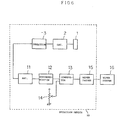
- a detection device 10 connected to a windshield wiper system as a second embodiment of this invention.
- the device 10 includes detection electrode member 1, oscillation circuit 2 coupled with the member 1, and detection circuit 3 associated with the circuit 2.
- the respective member 1, circuit 2 and circuit 3 are constructed with the same components as those of the above-mentioned first embodiment.
- the detection device 10 further includes an inverted amplifier 11 for amplifying th outputs from the detection circuit 3, a differentiation circuit 12, a comparator 13, a reference level source 14 and a wiper driver 15.
- the differentiation circuit 12 is disposed to avoid the changes of the oscillation amplitude by temperature changes applied to the circuits 2 and 3 and the amplifier 11 in long time use or by gradually obscuring the glass plate 7 with stain or dirt in long time period, so that it applies only a rapid change of the oscillation amplitude by the adhesion of water drops to the comparator 13.
- the comparator 13 is applied by a reference level voltage from the reference level source 14 to generate a detection signal when the output from the circuit 12 exceeds the reference level voltage, the detection signal being applied to the wiper driver 15 which drives a wiper system 16 by supplying a drive signal thereto.
- the detection device 10 may be installed onto a predetermined position of a windshield 18 of a vehicle, behind a rearview mirror 17 as shown in Fig. 7.
- the device 10 is mounted on an inner surface of the windshield glass plate 18 so as to be hidden by the mirror 17 within the view of the driver.
- Fig. 8 shows a front view of the vehicle installed by the device 10.
- the wiper system 16 includes arms 19 and rubber blades 20 contacting the glass plate 18.
- the blades 20 are driven through the arms 19 by a motor within the wiper system 16 which is adapted to be actuated by outputs from the wiper driver 15, and performs wiping fan- shaped area 21 of the windshield 18 on the reverse-side surface which the device 10 at its detection surface is mounted.
- the circuit constants of the bridge circuit of the oscillation circuit 2 is designed to oscillate the circuit 2 at a frequency, e.g. 1 MHz, where the difference between the curves A and B in Fig. 4 is the largest as explained in the foregoing first embodiment.
- the oscillation circuit 2 oscillates at 1 MHz.
- the oscillation frequency is set to the frequency at which the amplitude of the oscillation little varies by a water film on the windshield 18, so that the water film on the windshield 18 little changes the amplitude.
- the output from the inverted amplifier 11 slowly increases by temperature changes or the like through long time operations, but the output level of the differentiation circuit 12 becomes constant or is corrected as illustrated in Fig. 9 (b).
- the output from the oscillation circuit 12 is reduced and the output from the inverted amplifier 11 gradually increases as shown in Fig. 9 (a).
- the differentiation circuit 12 supplied the comparator 13 with the change of the output of the amplifier 11 as shown in Fig. 9 (b).
- the comparator 13 applies its output shown in Fig. 9 (c) to the wiper driver 15.
- the wiper driver 15 drives the wiper system 16 in response to the rising of the output signal from the comparator 13 for a predetermined time period.
- the wiper system 16 starts the wiping operation shown in Fig. 9 (e).
- the amplifier 11 When one of the blades 20 comes into the detection device 10 at its detection electrode member 1 with wiping water drops on the windshield 18 from its original position in a forward direction, the amplifier 11 generates a peak signal at time point t5 due to the wiped water by the blade. If the blades 20 pass the device 10, the water drops adjacent to the device 10 are wiped away, so that the output from the amplifier 11 is rapidly reduced just after the time point t5.
- the comparator 13 If it successively rains, however, the output from the amplifier 11 again increases after the time point t5 and when the output from the circuit 12 reaches the reference level Vref or the blade 20 again comes to the device 10 in a returning direction, the comparator 13 generates a second output signal prior to a time point t6 as illustrated in Fig. 9 (c). In response to the second output from the comparator 13, the driver 15 produces a second output pulse during the time when the blades 20 are still moving to their original position, so that it does not change the wiping operation as illustrated in Fig. 9 (e).
- the wiper driver 15 allows the wiper system 16 to restart.
- these operations will repeat as long as it rains. Since the time period from t4 to t7 continuously varies with the volume of the drops of water, every wiping cycle can be continuously changes according to the volume of rainfall. If it rains harder, the cycle of the output from the driver 15 becomes shorter and the rest period of the blades 20 also becomes shorter. As the volume of rainfall decreases, the rest period of the blades 20, viz. stopping period of the wiper system 16, becomes longer.
- the wiper system of this embodiment automatically starts when it start raining, automatically quicken its wiping cycles as it rains harder, and automatically stops when it stops raining.
- the device 10 is mounted on an upper portion of the windshield 18, whereby snow adhering to the windshield from the front hood by blowing when the vehicle runs faster than a predetermined speed is sensed by the device 10 to drive the wiper system 16.
- the device includes at its front surface a detection surface 31 and is housed within a housing 32.
- a detection electrode 31a On an inner surface of the housing 32 opposing to the detection surface 31, there are mounted a detection electrode 31a, a ring-shaped sub-electrode 31b surrounding the electrode 31a, and a ground terminal 31c at intervals of a predetermined distance from the electrode 31b in the same construction as that of Fig. 2.
- the detection surface 31 is formed at a slant angle along an angle of a windshield.
- the housing 32 is made of synthetic resin, and at its inner wall surfaces provided with a shield film 33 electrically connected with the ground electrode 31c covering inner circuitry within the housing 32.
- the inner circuitry is assembled on a printed-circuit-board 34 and a connecting cable therefrom extends downwardly.
- Fig. 11 illustrates assembling components to mount the device into a front portion of a dash board 36 as illustrated in Fig. 12.
- the board 36 at its front portion includes a recessed portion 36a fitting the housing 32.
- the cable 35 extends through a hole 36c, and a cover 38 fits a step 36b of the board 36 with pushing the housing 32 toward the windshield 37 by a leaf spring 39b shown in Fig. 13 whereby the detection surface 31 is fitted to the windshield 37 at an area to be wiped by blades of its wiper system.
- the device of this embodiment is completely hidden within the dash board, so that ornamental design is improved without hindering driver's view.
- the detection device includes detection sub-electrode to provide a pair of capacitors in the electrodes and perform temperature compensation for oscillation frequency by employing the bridge circuit as the resonance circuit. If desired, however, the sub-electrode may be omitted to simplify the construction of the device.
- the detection device of the above embodiments may be applied to rear window wiper systems of vehicles, and other windshield wiper systems of vehicles or aircrafts.
- the detection device may be modified to detect not only water but also other materials, such as oil, dust or the like, by selecting the best oscillation frequency.
- the detection device may be further applied to other sensor systems which sense any materials adhering to its sensing surface.
Abstract
Description
- This invention relates to a capacitive-type detection device for detecting an object or water adjacent to the device, and more particularly, to an improved capacitive-type detection device for detecting water on a windshield to control windshield wiper systems employed in vehicles, vessels or aircrafts.
- Windshield wiper systems for automotive vehicles are conventionally set or reset with manual operations by drivers. When the windshield is wet and obscured by rain or a dense fog on driving the vehicle, the driver must actuate a manual wiper switch to start the windshield wiper system for wiping the wet windshield. The manual operation on the driving is, however, troublesome to the driver and unfavorable in view of safety driving.
- It is, therefore, a primary object of this invention to provide a capacitive-type detection device for detecting a predetermined existence of an object or water adjacent to the device which may be applied to not only windshield wiper systems but also other universal control systems.
- It is a further object of this invention to provide a capacitive-type detection device which may be coupled with a wind shield wiper system so that when the windshield is obscured by water or foreign matters, the wiper system automatically wipe the windshield without any manual operations.
- It is a still further object of this invention to provide an improved detection device including detection electrodes and detection circuit for sensing the capacitive changes by water or foreign matters between the detection electrodes.
- According to this invention, there is provided a detection device which includes a detection wall member for sensing a predetermined existence of an object adjacent to the device, a detection electrode member including a detection electrode and a ground electrode which are disposed in the detection wall member, oscillation circuit member including a resonance circuit associated with a capacitance between the detection and ground electrodes, and detection circuit member for detecting change of oscillation of the oscillation circuit member by change of the capacitance between the electrodes so that the predetermined existence of the object, such as drops of water, a water film or other liquid status, adjacent to the detection wall member be detected by the device.
- Further objects and advantages of this invention will become apparent from the following detailed description and the accompanying drawings in which:
- Fig. 1 is a circuit diagram of a detection device as a preferred first embodiment of this invention;
- Fig. 2 is a schematic top plan view of the detection device of Fig. with its housing removed;
- Fig. 3 is a schematic sectional side view of the device of Fig. 2 which is mounted on a glass windshield;
- Fig. 4 illustrates changes of an output developed in the device relative to oscillation frequency;
- Fig. 5 is a graph illustrating wave forms in the circuit of Fig. 1;
- Fig. 6 is a schematic block diagram of a detection device coupled with windshield wiper driver as a second embodiment of this invention;
- Figs. 7 and 8 illustrate the detection device of Fig. 6 mounted on a windshield of an automotive vehicle;
- Fig. 9 shows wave forms developed in the block diagram of Fig. 6;
- Fig. 10 is a schematic sectional side view of a detection device as a third embodiment of this invention;
- Fig. 11 illustrates the device of Fig. 10 and a mounting member for a vehicle;
- Fig. 12 is partial sectional view illustrating the device of Fig. 10 mounted on a windshield of the vehicle; and
- Fig. 13 is a side view of the mounting member.
- Referring, now, to Fig. 1, there is shown a circuit diagram of a capacitive-type detection device as a first embodiment of this invention. The detection device includes a
detection electrode member 1, anoscillation circuit 2 coupled with theelectrode member 1 which oscillates at a frequency defined by a capacitance of the electrode member, and adetection circuit 3 for detecting an output signal from theoscillation circuit 2. Thedetection electrode member 1 includes an elongated oval-shaped eletrode la, a ring-shaped sub-electrode lb surrounding the electrode la, and aground electrode 1c surrounding the electrode lb at intervals of a predetermined distance therefrom, as illustrated in Fig. 2 which shows top surface of the detection device with its housing removed. The electrodes la, lb and 1c are respectively connected toterminals electrodes 1a and lb and the capacitance C2 between electrodes la and lc are respectively applied to resistors Rl and R2 in parallel therewith. Theoscillation circuit 2 includes transistors Tr.1 and Tr2 which are connected in series to provide an amplifier where the resistor Rl is connected between the emitter of transistor Tr2 and the base of transistor Trl and the resistor R2 is connected between the base of the transistor Trl and ground. The emitter of the transistor Tr1 is grounded through resistor R3 and connected to a movable contact of a variable resistor R4 through a capacitor C3. The resistor R4 is disposed to vary its oscillation frequency, and serves together with resistor R5 as an emitter resistance of the transistor Tr2. Thus, a bridge circuit is constituted by resistor Rl, capacitance Cl and resistor R2, capacitance C2, resistors R3 and R4, and capacitance Cl, which defines the oscillation frequency. The output from theoscillation circuit 2 is applied to thedetection circuit 3 where it is applied to transistor Tr3 through capacitor C4 and resistor R6. Thedetection circuit 3, which includes a smoothing circuit consisting of capacitors C5 and C6 and resistor R7, amplifies and detects the high frequency signal applied thereto from theoscillation circuit 2. - Fig. 3 shows a sectional side view illustrating an assembled construction of the detection device of this embodiment. The top surface of the device is mounted on an inner surface of
glass plate 7 of a windshield, while an outer surface of theplate 7 is externally exposed to be wet with a drop of water or rain. The device is covered with ahousing 8 made of synthetic resin. Thedetection electrode member 1 including electrodes la, lb and lc illustrated in Fig. 2 is mounted on an inner surface of a top wall or detection wall member of thehousing 8. The ground electrode lc is formed as a single unit together with ametal shielding cover 9 housing the oscillation and detection circuits within thehousing 8. If desired, theelectrode member 1 may be exposed on an external surface of thehousing 8 or burried within the housing. - Fig. 4 illustrates variations of the output voltage in the
oscillation circuit 2 at various oscillation frequencies. When a water thin film uniformly adheres to the outer surface of theglass plate 7, the variation of the output voltage of thecircuit 2 with respect to frequencies is represented by a curve A. When drops of water adhere to theglass plate 7, the variation of the output voltage with respect to frequencies is represented by a curve B. If this device is applied to a windshield wiper system for automotive vehicle by utilizing this device as a drive signal for the windshield wiper system, the wiper system is not necessary to be actuated when a thin water film remains or the windshield after actuating the wiper system once or several times because such a thin water film is dried up in a short time period without substantially obscuring driver's view through the windshield. Accordingly, the detection device is not necessary to generate any detection signal in this case. When drops of water adhere to the windshield, however, the wiper system must be actuated immediately because such drops obscure the drive's view, viz. a detection signal must be generated from the device. It is, therefore, desirable that the variation of the output from theoscillation circuit 2 by such water film is small as far as possible and the variation by the drops of water is large. Accordingly, theoscillation circuit 2 is designed to have an oscillation frequency within a frequency band in which the variation (curve B) of the output voltage of thecircuit 2 by the drops of water is larger than that (curve A) by the water film. In this embodiment, thecircuit 2 is designed to oscillate at a frequency around 1 MHz within a band shown by partial hatching in Fig. 4 so as to be easy to only detect drops of water on the outer surface of theglass plate 7. By adjusting circuit constants of the bridge circuit of theoscillation circuit 2, thecircuit 2 can oscillate at the best frequency (herein, 1 MHz) where the difference between the curves A and B is the largest. - As a power source is connected between terminals Vcc and GND of Fig. 1, the
oscillation circuit 2 generates an a.c. output prior to a time point tl as illustrated in Fig. 5 (a) where the outside surface of the glass plate 7 (Fig. 3) is dry. When a water film adheres to theplate 7 at the time point tl, the amplitude of the a.c. output slightly varies. When drops of water adhere to the plate at a time point t2, the amplitude of the a.c..output greatly varies to a larger amplitude as illustrated in Fig. 5 (a) and the collector voltage of the transistor Tr3 is reduced, so that the output from thedetection circuit 3 is also reduced as illustrated in Fig. 5 (b). Thus, the output from thedetection circuit 3 represents whether or not there exist drops of water on theglass plate 7. - In Fig. 6, there is shown a
detection device 10 connected to a windshield wiper system as a second embodiment of this invention. Thedevice 10 includesdetection electrode member 1,oscillation circuit 2 coupled with themember 1, anddetection circuit 3 associated with thecircuit 2. Therespective member 1,circuit 2 andcircuit 3 are constructed with the same components as those of the above-mentioned first embodiment. Thedetection device 10 further includes an invertedamplifier 11 for amplifying th outputs from thedetection circuit 3, adifferentiation circuit 12, acomparator 13, areference level source 14 and awiper driver 15. Thedifferentiation circuit 12 is disposed to avoid the changes of the oscillation amplitude by temperature changes applied to thecircuits amplifier 11 in long time use or by gradually obscuring theglass plate 7 with stain or dirt in long time period, so that it applies only a rapid change of the oscillation amplitude by the adhesion of water drops to thecomparator 13. Thecomparator 13 is applied by a reference level voltage from thereference level source 14 to generate a detection signal when the output from thecircuit 12 exceeds the reference level voltage, the detection signal being applied to thewiper driver 15 which drives awiper system 16 by supplying a drive signal thereto. - The
detection device 10 may be installed onto a predetermined position of awindshield 18 of a vehicle, behind arearview mirror 17 as shown in Fig. 7. Thedevice 10 is mounted on an inner surface of thewindshield glass plate 18 so as to be hidden by themirror 17 within the view of the driver. Fig. 8 shows a front view of the vehicle installed by thedevice 10. Thewiper system 16 includesarms 19 andrubber blades 20 contacting theglass plate 18. Theblades 20 are driven through thearms 19 by a motor within thewiper system 16 which is adapted to be actuated by outputs from thewiper driver 15, and performs wiping fan- shapedarea 21 of thewindshield 18 on the reverse-side surface which thedevice 10 at its detection surface is mounted. - Referring to Fig. 9 the operations by the device of Fig. 6 will be explained hereinafter. The circuit constants of the bridge circuit of the
oscillation circuit 2 is designed to oscillate thecircuit 2 at a frequency, e.g. 1 MHz, where the difference between the curves A and B in Fig. 4 is the largest as explained in the foregoing first embodiment. As thedevice 10 is supplied with power from a battery or power source, theoscillation circuit 2 oscillates at 1 MHz. The oscillation frequency is set to the frequency at which the amplitude of the oscillation little varies by a water film on thewindshield 18, so that the water film on thewindshield 18 little changes the amplitude. As shown in Fig. 9 (a) the output from theinverted amplifier 11 slowly increases by temperature changes or the like through long time operations, but the output level of thedifferentiation circuit 12 becomes constant or is corrected as illustrated in Fig. 9 (b). - As at a time point t3 it starts raining and drops of water adhere to the
windshield 18, the output from theoscillation circuit 12 is reduced and the output from theinverted amplifier 11 gradually increases as shown in Fig. 9 (a). Then, thedifferentiation circuit 12 supplied thecomparator 13 with the change of the output of theamplifier 11 as shown in Fig. 9 (b). At a time point t4 when the input applied to thecomparator 13 reaches the reference level Vref from thesource 14, thecomparator 13 applies its output shown in Fig. 9 (c) to thewiper driver 15. As shown in Fig. 9 (d), thewiper driver 15 drives thewiper system 16 in response to the rising of the output signal from thecomparator 13 for a predetermined time period. Successively thewiper system 16 starts the wiping operation shown in Fig. 9 (e). When one of theblades 20 comes into thedetection device 10 at itsdetection electrode member 1 with wiping water drops on thewindshield 18 from its original position in a forward direction, theamplifier 11 generates a peak signal at time point t5 due to the wiped water by the blade. If theblades 20 pass thedevice 10, the water drops adjacent to thedevice 10 are wiped away, so that the output from theamplifier 11 is rapidly reduced just after the time point t5. If it successively rains, however, the output from theamplifier 11 again increases after the time point t5 and when the output from thecircuit 12 reaches the reference level Vref or theblade 20 again comes to thedevice 10 in a returning direction, thecomparator 13 generates a second output signal prior to a time point t6 as illustrated in Fig. 9 (c). In response to the second output from thecomparator 13, thedriver 15 produces a second output pulse during the time when theblades 20 are still moving to their original position, so that it does not change the wiping operation as illustrated in Fig. 9 (e). If it still rains after the above-mentioned one wiping cycle, th output from theamplifier 11 again increases and when the output from thecircuit 12 reaches the reference level Vref at a time point t7, thewiper driver 15 allows thewiper system 16 to restart. Thus, these operations will repeat as long as it rains. Since the time period from t4 to t7 continuously varies with the volume of the drops of water, every wiping cycle can be continuously changes according to the volume of rainfall. If it rains harder, the cycle of the output from thedriver 15 becomes shorter and the rest period of theblades 20 also becomes shorter. As the volume of rainfall decreases, the rest period of theblades 20, viz. stopping period of thewiper system 16, becomes longer. Thus, the wiper system of this embodiment automatically starts when it start raining, automatically quicken its wiping cycles as it rains harder, and automatically stops when it stops raining. - The
device 10 is mounted on an upper portion of thewindshield 18, whereby snow adhering to the windshield from the front hood by blowing when the vehicle runs faster than a predetermined speed is sensed by thedevice 10 to drive thewiper system 16. - Returning to Fig. 10, there is shown a side sectional view of a detection device as a third embodiment of this invention. As illustrated in the foregoing embodiments, the device includes at its front surface a
detection surface 31 and is housed within ahousing 32. On an inner surface of thehousing 32 opposing to thedetection surface 31, there are mounted adetection electrode 31a, a ring-shaped sub-electrode 31b surrounding theelectrode 31a, and a ground terminal 31c at intervals of a predetermined distance from theelectrode 31b in the same construction as that of Fig. 2. Thedetection surface 31 is formed at a slant angle along an angle of a windshield. Thehousing 32 is made of synthetic resin, and at its inner wall surfaces provided with ashield film 33 electrically connected with the ground electrode 31c covering inner circuitry within thehousing 32. The inner circuitry is assembled on a printed-circuit-board 34 and a connecting cable therefrom extends downwardly. - Fig. 11 illustrates assembling components to mount the device into a front portion of a
dash board 36 as illustrated in Fig. 12. Theboard 36 at its front portion includes a recessedportion 36a fitting thehousing 32. As the components of Fig. 11 are assembled, thecable 35 extends through ahole 36c, and acover 38 fits astep 36b of theboard 36 with pushing thehousing 32 toward thewindshield 37 by a leaf spring 39b shown in Fig. 13 whereby thedetection surface 31 is fitted to thewindshield 37 at an area to be wiped by blades of its wiper system. The device of this embodiment is completely hidden within the dash board, so that ornamental design is improved without hindering driver's view. - In the foregoing embodiments, the detection device includes detection sub-electrode to provide a pair of capacitors in the electrodes and perform temperature compensation for oscillation frequency by employing the bridge circuit as the resonance circuit. If desired, however, the sub-electrode may be omitted to simplify the construction of the device.
- The detection device of the above embodiments may be applied to rear window wiper systems of vehicles, and other windshield wiper systems of vehicles or aircrafts. The detection device may be modified to detect not only water but also other materials, such as oil, dust or the like, by selecting the best oscillation frequency. The detection device may be further applied to other sensor systems which sense any materials adhering to its sensing surface.
- The above description is of preferred embodiments of this invention and many modifications may be made thereto without departing from the spirit and scope of this invention.
Claims (13)
Applications Claiming Priority (6)
| Application Number | Priority Date | Filing Date | Title |
|---|---|---|---|
| JP196142/84 | 1984-09-19 | ||
| JP59196142A JPS6175251A (en) | 1984-09-19 | 1984-09-19 | Water drop detection sensor |
| JP14382284U JPS6157849U (en) | 1984-09-21 | 1984-09-21 | |
| JP59199061A JPS6176946A (en) | 1984-09-21 | 1984-09-21 | Water quantity-sensitive window wiper |
| JP199061/84 | 1984-09-21 | ||
| JP143822/84U | 1984-09-21 |
Publications (2)
| Publication Number | Publication Date |
|---|---|
| EP0175362A2 true EP0175362A2 (en) | 1986-03-26 |
| EP0175362A3 EP0175362A3 (en) | 1988-12-07 |
Family
ID=27318720
Family Applications (1)
| Application Number | Title | Priority Date | Filing Date |
|---|---|---|---|
| EP85111828A Ceased EP0175362A3 (en) | 1984-09-19 | 1985-09-18 | Capacitive-type detection device |
Country Status (3)
| Country | Link |
|---|---|
| US (1) | US4748390A (en) |
| EP (1) | EP0175362A3 (en) |
| KR (1) | KR910005905B1 (en) |
Cited By (11)
| Publication number | Priority date | Publication date | Assignee | Title |
|---|---|---|---|---|
| US4859867A (en) * | 1988-04-19 | 1989-08-22 | Donnelly Corporation | Windshield moisture sensing control circuit |
| US4871917A (en) * | 1988-04-19 | 1989-10-03 | Donnelly Corporation | Vehicular moisture sensor and mounting apparatus therefor |
| US4916374A (en) * | 1989-02-28 | 1990-04-10 | Donnelly Corporation | Continuously adaptive moisture sensor system for wiper control |
| US4956591A (en) * | 1989-02-28 | 1990-09-11 | Donnelly Corporation | Control for a moisture sensor |
| US4973844A (en) * | 1989-07-10 | 1990-11-27 | Donnelly Corporation | Vehicular moisture sensor and mounting apparatus therefor |
| EP0438634A2 (en) * | 1990-01-23 | 1991-07-31 | VDO Adolf Schindling AG | Evaluation circuit for a capacitive sensor |
| GB2271642A (en) * | 1992-10-19 | 1994-04-20 | De La Rue Syst | Conductive strip detector |
| FR2722287A1 (en) * | 1994-07-08 | 1996-01-12 | Seikosha Kk | DEVICE FOR DETECTION OF OBJECTS. |
| US5880538A (en) * | 1996-05-20 | 1999-03-09 | I F M Electronic Gmbh | Capacitive proximity switch circuit |
| WO2009068991A1 (en) * | 2007-11-30 | 2009-06-04 | Toyota Jidosha Kabushiki Kaisha | Capacitance touch sensing device and door locking device |
| WO2012032318A1 (en) * | 2010-09-09 | 2012-03-15 | Randox Laboratories Ltd. | Capacitive liquid level sensor |
Families Citing this family (52)
| Publication number | Priority date | Publication date | Assignee | Title |
|---|---|---|---|---|
| US4827198A (en) * | 1988-02-09 | 1989-05-02 | General Motors Corporation | Vehicle windshield and wiper with rain sensor |
| DE3918331A1 (en) * | 1989-01-05 | 1990-12-06 | Sattlecker Armin | DEPENDENT-CONTROLLED CONTROL FOR COVERING SYSTEMS |
| GB8911274D0 (en) * | 1989-05-17 | 1989-07-05 | Moonstone Computers Ltd | Proximity sensor |
| GB2250822B (en) * | 1989-05-17 | 1993-08-11 | Moonstone Designs Ltd | Proximity sensor |
| JPH0396253U (en) * | 1990-01-24 | 1991-10-01 | ||
| JP3481720B2 (en) * | 1995-03-31 | 2003-12-22 | 株式会社リコー | Surface potential measuring device |
| US6373263B1 (en) * | 2000-04-20 | 2002-04-16 | Millennium Sensors Ltd. | Differential windshield capacitive rain sensor |
| US6802205B2 (en) * | 2002-02-28 | 2004-10-12 | Ppg Industries Ohio, Inc. | Moisture detection system and method of use thereof |
| CA2475300C (en) * | 2002-02-28 | 2007-11-20 | Ppg Industries Ohio, Inc. | Moisture detection system and method of use thereof |
| US7204130B2 (en) * | 2002-12-03 | 2007-04-17 | Ppg Industries Ohio, Inc. | Windshield moisture detector |
| US7296461B2 (en) * | 2002-12-03 | 2007-11-20 | Ppg Industries Ohio, Inc. | Temperature compensated windshield moisture detector |
| US7263875B2 (en) * | 2004-10-11 | 2007-09-04 | Ppg Industries Ohio, Inc. | Multi-layer windshield moisture detector |
| EP2109774B1 (en) | 2007-02-15 | 2018-07-04 | Advanced Liquid Logic, Inc. | Capacitance detection in a droplet actuator |
| KR101549455B1 (en) * | 2007-04-20 | 2015-09-03 | 티+잉크, 인코포레이티드 | In-molded capacitive switch |
| US8198979B2 (en) * | 2007-04-20 | 2012-06-12 | Ink-Logix, Llc | In-molded resistive and shielding elements |
| CN101419493B (en) * | 2007-10-25 | 2012-06-20 | 鸿富锦精密工业(深圳)有限公司 | Fan running monitoring device |
| KR100943401B1 (en) * | 2008-06-05 | 2010-02-19 | 우리산업 주식회사 | Rain Sensor for Vehicle and Sensing Method thereof |
| US8283800B2 (en) | 2010-05-27 | 2012-10-09 | Ford Global Technologies, Llc | Vehicle control system with proximity switch and method thereof |
| US8454181B2 (en) | 2010-08-25 | 2013-06-04 | Ford Global Technologies, Llc | Light bar proximity switch |
| US8575949B2 (en) | 2010-08-25 | 2013-11-05 | Ford Global Technologies, Llc | Proximity sensor with enhanced activation |
| WO2012068055A2 (en) * | 2010-11-17 | 2012-05-24 | Advanced Liquid Logic, Inc. | Capacitance detection in a droplet actuator |
| CA2833897C (en) | 2011-05-09 | 2020-05-19 | Advanced Liquid Logic, Inc. | Microfluidic feedback using impedance detection |
| US8928336B2 (en) | 2011-06-09 | 2015-01-06 | Ford Global Technologies, Llc | Proximity switch having sensitivity control and method therefor |
| US8975903B2 (en) | 2011-06-09 | 2015-03-10 | Ford Global Technologies, Llc | Proximity switch having learned sensitivity and method therefor |
| US10004286B2 (en) | 2011-08-08 | 2018-06-26 | Ford Global Technologies, Llc | Glove having conductive ink and method of interacting with proximity sensor |
| US9143126B2 (en) | 2011-09-22 | 2015-09-22 | Ford Global Technologies, Llc | Proximity switch having lockout control for controlling movable panel |
| US8994228B2 (en) | 2011-11-03 | 2015-03-31 | Ford Global Technologies, Llc | Proximity switch having wrong touch feedback |
| US10112556B2 (en) | 2011-11-03 | 2018-10-30 | Ford Global Technologies, Llc | Proximity switch having wrong touch adaptive learning and method |
| US8878438B2 (en) | 2011-11-04 | 2014-11-04 | Ford Global Technologies, Llc | Lamp and proximity switch assembly and method |
| US9559688B2 (en) | 2012-04-11 | 2017-01-31 | Ford Global Technologies, Llc | Proximity switch assembly having pliable surface and depression |
| US9219472B2 (en) | 2012-04-11 | 2015-12-22 | Ford Global Technologies, Llc | Proximity switch assembly and activation method using rate monitoring |
| US8933708B2 (en) | 2012-04-11 | 2015-01-13 | Ford Global Technologies, Llc | Proximity switch assembly and activation method with exploration mode |
| US9197206B2 (en) | 2012-04-11 | 2015-11-24 | Ford Global Technologies, Llc | Proximity switch having differential contact surface |
| US9831870B2 (en) | 2012-04-11 | 2017-11-28 | Ford Global Technologies, Llc | Proximity switch assembly and method of tuning same |
| US9184745B2 (en) | 2012-04-11 | 2015-11-10 | Ford Global Technologies, Llc | Proximity switch assembly and method of sensing user input based on signal rate of change |
| US9520875B2 (en) | 2012-04-11 | 2016-12-13 | Ford Global Technologies, Llc | Pliable proximity switch assembly and activation method |
| US9660644B2 (en) | 2012-04-11 | 2017-05-23 | Ford Global Technologies, Llc | Proximity switch assembly and activation method |
| US9065447B2 (en) | 2012-04-11 | 2015-06-23 | Ford Global Technologies, Llc | Proximity switch assembly and method having adaptive time delay |
| US9568527B2 (en) | 2012-04-11 | 2017-02-14 | Ford Global Technologies, Llc | Proximity switch assembly and activation method having virtual button mode |
| US9287864B2 (en) | 2012-04-11 | 2016-03-15 | Ford Global Technologies, Llc | Proximity switch assembly and calibration method therefor |
| US9531379B2 (en) | 2012-04-11 | 2016-12-27 | Ford Global Technologies, Llc | Proximity switch assembly having groove between adjacent proximity sensors |
| US9944237B2 (en) | 2012-04-11 | 2018-04-17 | Ford Global Technologies, Llc | Proximity switch assembly with signal drift rejection and method |
| US9136840B2 (en) | 2012-05-17 | 2015-09-15 | Ford Global Technologies, Llc | Proximity switch assembly having dynamic tuned threshold |
| US8981602B2 (en) | 2012-05-29 | 2015-03-17 | Ford Global Technologies, Llc | Proximity switch assembly having non-switch contact and method |
| US9337832B2 (en) | 2012-06-06 | 2016-05-10 | Ford Global Technologies, Llc | Proximity switch and method of adjusting sensitivity therefor |
| US9641172B2 (en) | 2012-06-27 | 2017-05-02 | Ford Global Technologies, Llc | Proximity switch assembly having varying size electrode fingers |
| US8922340B2 (en) | 2012-09-11 | 2014-12-30 | Ford Global Technologies, Llc | Proximity switch based door latch release |
| US8796575B2 (en) | 2012-10-31 | 2014-08-05 | Ford Global Technologies, Llc | Proximity switch assembly having ground layer |
| US9311204B2 (en) | 2013-03-13 | 2016-04-12 | Ford Global Technologies, Llc | Proximity interface development system having replicator and method |
| US10038443B2 (en) | 2014-10-20 | 2018-07-31 | Ford Global Technologies, Llc | Directional proximity switch assembly |
| US9654103B2 (en) | 2015-03-18 | 2017-05-16 | Ford Global Technologies, Llc | Proximity switch assembly having haptic feedback and method |
| US9548733B2 (en) | 2015-05-20 | 2017-01-17 | Ford Global Technologies, Llc | Proximity sensor assembly having interleaved electrode configuration |
Citations (9)
| Publication number | Priority date | Publication date | Assignee | Title |
|---|---|---|---|---|
| US3593073A (en) * | 1968-12-16 | 1971-07-13 | Wagner Electric Corp | Antenna system for capacitance responsive circuit |
| DE2022823A1 (en) * | 1970-05-11 | 1971-12-02 | Bischoff Hans Gerhard | Humidity controlled regulator |
| FR2195875A1 (en) * | 1972-08-10 | 1974-03-08 | Bosch Gmbh Robert | |
| DE2523111A1 (en) * | 1975-05-24 | 1976-12-02 | Wilfried Von Der Ohe | Automatic control for windscreen wiper - with thin film moisture detector on outside of glass |
| DE2739786A1 (en) * | 1977-09-03 | 1979-03-15 | Turck Werner Kg | Capacitive proximity switch with two concentric electrodes - forms capacitor encircled by earthed screen electrode |
| WO1981001470A1 (en) * | 1979-11-15 | 1981-05-28 | Surface Systems | Apparatus and method for detecting wet and icy conditions on the surface of a pathway |
| WO1983002093A1 (en) * | 1981-12-08 | 1983-06-23 | Boegh-Petersen, Allan | Windshield wiper control having a sensor |
| JPS58185314A (en) * | 1982-04-26 | 1983-10-29 | Nippon Denso Co Ltd | Signal line extracting structure on front glass |
| JPS5948241A (en) * | 1982-09-13 | 1984-03-19 | Nissan Motor Co Ltd | Sensor for light volume |
Family Cites Families (15)
| Publication number | Priority date | Publication date | Assignee | Title |
|---|---|---|---|---|
| US3649898A (en) * | 1968-09-21 | 1972-03-14 | Nippon Denso Co | Windshield wiper control apparatus |
| US3614664A (en) * | 1970-07-08 | 1971-10-19 | Spacetac Inc | Class c bridge oscillator |
| DE2057062A1 (en) * | 1970-11-20 | 1972-05-25 | Meyer, Manfred, 8501 Moorenbrunn | Humidity-dependent switching device, in particular for use in vehicles |
| DE2345546A1 (en) * | 1973-09-10 | 1975-03-20 | Schmidt Karl Heinz | Automatic control for windscreen wiper - with capacitative moisture sensor on inside of windscreen under wiped area |
| US4131834A (en) * | 1975-02-13 | 1978-12-26 | Henry Blaszkowski | Windshield wiper control system |
| US4347741A (en) * | 1980-07-17 | 1982-09-07 | Endress & Hauser, Inc. | Control system for a capacitive level sensor |
| JPS609696Y2 (en) * | 1980-11-20 | 1985-04-05 | 株式会社日本自動車部品総合研究所 | Liquid level detection device |
| US4513257A (en) * | 1981-12-03 | 1985-04-23 | Omron Tateisi Electronics Co. | Proximity switch with oppositely polarized coils |
| IT1156372B (en) * | 1982-06-22 | 1987-02-04 | Fiat Auto Spa | AUTOMATIC ADJUSTMENT OF THE FREQUENCY OF ACTIVATION OF A WINDSCREEN WIPER FOR VEHICLES |
| US4527105A (en) * | 1982-09-02 | 1985-07-02 | Nissan Motor Company, Limited | Automatic windshield wiper speed control with piezoelectric sensor |
| JPS59137842A (en) * | 1983-01-28 | 1984-08-08 | Jidosha Denki Kogyo Co Ltd | Structure for holding vibrating plate of rain drop detector |
| JPS607342A (en) * | 1983-06-28 | 1985-01-16 | Nippon Denso Co Ltd | Liquid detector for windshield-wiper automatic-control device |
| US4595866A (en) * | 1983-10-27 | 1986-06-17 | Nippondenso Co., Ltd. | Windshield wiper control apparatus |
| US4554493A (en) * | 1984-02-29 | 1985-11-19 | Armstrong Howard L | Automated windshield wiper system |
| US4567412A (en) * | 1984-11-29 | 1986-01-28 | General Motors Corporation | Automatic wiper actuator for a vehicle window |
-
1985
- 1985-09-18 EP EP85111828A patent/EP0175362A3/en not_active Ceased
- 1985-09-18 US US06/777,432 patent/US4748390A/en not_active Expired - Fee Related
- 1985-09-19 KR KR1019850006855A patent/KR910005905B1/en active IP Right Grant
Patent Citations (9)
| Publication number | Priority date | Publication date | Assignee | Title |
|---|---|---|---|---|
| US3593073A (en) * | 1968-12-16 | 1971-07-13 | Wagner Electric Corp | Antenna system for capacitance responsive circuit |
| DE2022823A1 (en) * | 1970-05-11 | 1971-12-02 | Bischoff Hans Gerhard | Humidity controlled regulator |
| FR2195875A1 (en) * | 1972-08-10 | 1974-03-08 | Bosch Gmbh Robert | |
| DE2523111A1 (en) * | 1975-05-24 | 1976-12-02 | Wilfried Von Der Ohe | Automatic control for windscreen wiper - with thin film moisture detector on outside of glass |
| DE2739786A1 (en) * | 1977-09-03 | 1979-03-15 | Turck Werner Kg | Capacitive proximity switch with two concentric electrodes - forms capacitor encircled by earthed screen electrode |
| WO1981001470A1 (en) * | 1979-11-15 | 1981-05-28 | Surface Systems | Apparatus and method for detecting wet and icy conditions on the surface of a pathway |
| WO1983002093A1 (en) * | 1981-12-08 | 1983-06-23 | Boegh-Petersen, Allan | Windshield wiper control having a sensor |
| JPS58185314A (en) * | 1982-04-26 | 1983-10-29 | Nippon Denso Co Ltd | Signal line extracting structure on front glass |
| JPS5948241A (en) * | 1982-09-13 | 1984-03-19 | Nissan Motor Co Ltd | Sensor for light volume |
Non-Patent Citations (3)
| Title |
|---|
| Funskschau, Vol. 50, No. 19, September 1978, pages 943-944, Munich, DE, K.-H. SCHMIDT: "Automatische Scheibenwischersteuerung", page 943, lines 1-40. * |
| PATENT ABSTRACTS OF JAPAN, Vol. 8, No. 152 (M-309)(1589), July 14, 1984; & JP,A,59 048 241 (NISSAN JIDOSHA K.K.) 19-03-1984, Figure. * |
| PATENT ABSTRACTS OF JAPAN, Vol. 8, No. 28, (M-274)(1465), February 7, 1984; & JP,A,58 185 314 (NIPPON DENSO K.K.) 29-10-1983, Abstract; figure. * |
Cited By (17)
| Publication number | Priority date | Publication date | Assignee | Title |
|---|---|---|---|---|
| US4859867A (en) * | 1988-04-19 | 1989-08-22 | Donnelly Corporation | Windshield moisture sensing control circuit |
| US4871917A (en) * | 1988-04-19 | 1989-10-03 | Donnelly Corporation | Vehicular moisture sensor and mounting apparatus therefor |
| US4916374A (en) * | 1989-02-28 | 1990-04-10 | Donnelly Corporation | Continuously adaptive moisture sensor system for wiper control |
| US4956591A (en) * | 1989-02-28 | 1990-09-11 | Donnelly Corporation | Control for a moisture sensor |
| US4973844A (en) * | 1989-07-10 | 1990-11-27 | Donnelly Corporation | Vehicular moisture sensor and mounting apparatus therefor |
| EP0438634A2 (en) * | 1990-01-23 | 1991-07-31 | VDO Adolf Schindling AG | Evaluation circuit for a capacitive sensor |
| EP0438634A3 (en) * | 1990-01-23 | 1992-03-04 | Vdo Adolf Schindling Ag | Evaluation circuit for a capacitive sensor |
| US5172065A (en) * | 1990-01-23 | 1992-12-15 | Vdo Adolf Schindling Ag | Evaluation circuit for a capacitive sensor |
| GB2271642A (en) * | 1992-10-19 | 1994-04-20 | De La Rue Syst | Conductive strip detector |
| GB2271642B (en) * | 1992-10-19 | 1996-06-05 | De La Rue Syst | Conductive strip detector |
| US5650729A (en) * | 1992-10-19 | 1997-07-22 | De La Rue Systems Limited | Conductive strip detector |
| FR2722287A1 (en) * | 1994-07-08 | 1996-01-12 | Seikosha Kk | DEVICE FOR DETECTION OF OBJECTS. |
| US5880538A (en) * | 1996-05-20 | 1999-03-09 | I F M Electronic Gmbh | Capacitive proximity switch circuit |
| WO2009068991A1 (en) * | 2007-11-30 | 2009-06-04 | Toyota Jidosha Kabushiki Kaisha | Capacitance touch sensing device and door locking device |
| US8305090B2 (en) | 2007-11-30 | 2012-11-06 | Toyota Jidosha Kabushiki Kaisha | Capacitance touch sensing device and door locking device |
| WO2012032318A1 (en) * | 2010-09-09 | 2012-03-15 | Randox Laboratories Ltd. | Capacitive liquid level sensor |
| US9766109B2 (en) | 2010-09-09 | 2017-09-19 | Randox Laboratories Ltd. | Capacitive liquid level sensor |
Also Published As
| Publication number | Publication date |
|---|---|
| KR860002382A (en) | 1986-04-24 |
| KR910005905B1 (en) | 1991-08-06 |
| US4748390A (en) | 1988-05-31 |
| EP0175362A3 (en) | 1988-12-07 |
Similar Documents
| Publication | Publication Date | Title |
|---|---|---|
| US4748390A (en) | Capacitive-type detection device | |
| US5266873A (en) | Automatically controlled cleaning device, notably for a motor vehicle windscreen | |
| US5203207A (en) | Raindrop sensor | |
| US5119002A (en) | Automatic windshield wiper apparatus with raindrop detector for automotive vehicles and methods for automatically controlling wiper apparatus | |
| US4620141A (en) | Rain-controlled windshield wipers | |
| EP0115338B1 (en) | Rain condition dependent wiper control system for an automotive vehicle | |
| US4613802A (en) | Proximity moisture sensor | |
| RU2369498C1 (en) | Moisture detection system and method of using thereof | |
| EP0117435B1 (en) | Rain sensor in an automatic wiper drive control system for an automotive vehicle | |
| JPS61143247A (en) | Control circuit for wiper operation of window for automobile | |
| US5900821A (en) | Rain sensor system for a motor vehicle | |
| JPH0379452A (en) | Method and device for adapting sensitivity of sensor device for detecting precipitation during control of window wiping distance of window wiping drive device | |
| US5821863A (en) | Rain sensor | |
| KR100609802B1 (en) | Moisture sensor with automatic emitter intensity control | |
| KR100943401B1 (en) | Rain Sensor for Vehicle and Sensing Method thereof | |
| JP2004523409A (en) | Automatic window cleaning device | |
| GB2105184A (en) | Control of windscreen wipers | |
| JPS6336292Y2 (en) | ||
| JP2829520B2 (en) | Wiper control device | |
| JPS6176946A (en) | Water quantity-sensitive window wiper | |
| JPH0527817B2 (en) | ||
| JPH06328998A (en) | Automatic control device of wiper | |
| JPH03136952A (en) | Wiper device | |
| JPH03136954A (en) | Wiper device | |
| JPH03136953A (en) | Wiper device |
Legal Events
| Date | Code | Title | Description |
|---|---|---|---|
| PUAI | Public reference made under article 153(3) epc to a published international application that has entered the european phase |
Free format text: ORIGINAL CODE: 0009012 |
|
| 17P | Request for examination filed |
Effective date: 19850918 |
|
| AK | Designated contracting states |
Kind code of ref document: A2 Designated state(s): AT BE CH DE FR GB IT LI LU NL SE |
|
| PUAL | Search report despatched |
Free format text: ORIGINAL CODE: 0009013 |
|
| AK | Designated contracting states |
Kind code of ref document: A3 Designated state(s): AT BE CH DE FR GB IT LI LU NL SE |
|
| 17Q | First examination report despatched |
Effective date: 19900608 |
|
| STAA | Information on the status of an ep patent application or granted ep patent |
Free format text: STATUS: THE APPLICATION HAS BEEN REFUSED |
|
| 18R | Application refused |
Effective date: 19910819 |
|
| RIN1 | Information on inventor provided before grant (corrected) |
Inventor name: SHOJI, SHINICHIC/O OMRON TATEISI ELECTRONICS CO. Inventor name: OKUSHIMA, AKIHIROC/O OMRON TATEISI ELECTR. CO. |