EP0165690A2 - Pneumatic powder dispensing method and apparatus - Google Patents
Pneumatic powder dispensing method and apparatus Download PDFInfo
- Publication number
- EP0165690A2 EP0165690A2 EP85303123A EP85303123A EP0165690A2 EP 0165690 A2 EP0165690 A2 EP 0165690A2 EP 85303123 A EP85303123 A EP 85303123A EP 85303123 A EP85303123 A EP 85303123A EP 0165690 A2 EP0165690 A2 EP 0165690A2
- Authority
- EP
- European Patent Office
- Prior art keywords
- powder
- mixing
- canister
- metering
- inlet
- Prior art date
- Legal status (The legal status is an assumption and is not a legal conclusion. Google has not performed a legal analysis and makes no representation as to the accuracy of the status listed.)
- Withdrawn
Links
Images


Classifications
-
- D—TEXTILES; PAPER
- D06—TREATMENT OF TEXTILES OR THE LIKE; LAUNDERING; FLEXIBLE MATERIALS NOT OTHERWISE PROVIDED FOR
- D06F—LAUNDERING, DRYING, IRONING, PRESSING OR FOLDING TEXTILE ARTICLES
- D06F39/00—Details of washing machines not specific to a single type of machines covered by groups D06F9/00 - D06F27/00
- D06F39/02—Devices for adding soap or other washing agents
-
- D—TEXTILES; PAPER
- D06—TREATMENT OF TEXTILES OR THE LIKE; LAUNDERING; FLEXIBLE MATERIALS NOT OTHERWISE PROVIDED FOR
- D06F—LAUNDERING, DRYING, IRONING, PRESSING OR FOLDING TEXTILE ARTICLES
- D06F33/00—Control of operations performed in washing machines or washer-dryers
- D06F33/30—Control of washing machines characterised by the purpose or target of the control
- D06F33/32—Control of operational steps, e.g. optimisation or improvement of operational steps depending on the condition of the laundry
- D06F33/37—Control of operational steps, e.g. optimisation or improvement of operational steps depending on the condition of the laundry of metering of detergents or additives
Definitions
- This invention relates to powder dispensers for washing machines and more particularly to a dispensing method and apparatus for dispensing dry detergents, bleaches and the like to washing machines.
- washing machines are capable of using powdered detergents, bleaches, water softeners and pH adjusters (sours). Widespread use of these powdered materials in washing machines has been hindered by several problems, however. Among the problems is the inability to precisely manually premeasure the appropriate amount of powdered product for the washing machine. Additionally, many machines are unable to automatically dispense such powdered materials to the washing container of the washing machine at the appropriate time(s) during the processing cycles.
- Another approach to the powder dispensing problem involves a relatively large powder hopper in which a large first amount of powdered detergent is stored.
- the dispensing system automatically meters out a second smaller amount of detergent from the hopper and pneumatically conveys this second amount directly to the washing container.
- this approach to the problem does not contemplate the use of a flush bin from which the powdered product is hydraulically flushed.
- this type of dispensing system also possesses several shortcomings. Importantly, such systems are not adjustable. That is, the "measuring station" which meters the smaller second amount of powder from the larger first amount stored in the hopper is not adjustable. Therefore, such systems are only compatible with one type of powder and one type of machine.
- Such dispensing systems include only one hopper so that only one powdered product can be dispensed to the washing container during a given machine cycle.
- the exit end or outlet end of the powder tube is in direct fluid communication with the washing container. This results in relatively uncontrolled mixing conditions and also results potentially in water spray from the washing container coming into contact with the end of the powder tube, thereby contributing to the encrustation of powder in the vicinity of the end of the tube, eventually occluding the end of the powder tube to some degree.
- Still other types of powder dispensers do not include means for metering the powder independent from the conveying means. That is, the powder is pneumatically conveyed to the washing container directly from the main hopper and the amount conveyed to the washing container depends on the flow rate of the air, the type of powder and the amount of time that the air flow is present.
- Such pneumatic powder dispensing systems suffer if the air flow varies due to problems with the fan, partial plugging of the line or variations in the powdered products. Also, if the period of time during which the fan is "on" is not accurately and repeatably controlled, the amount of powder delivered to the washing container will vary from cycle to cycle. Additionally, such systems are usually not adjustable to compensate for variations in the physical properties of the powdered products and changes in the length of tubing. Such changes should require longer or shorter fan "on" times and/or flow rates to convey the same amount of powder to the container.
- Still another type of conveying system in the prior art includes moving parts, for example brushes in contact with a screen, which directly and mechanically convey the powder through the system. It is perceived that such systems are prone to clog and maintenance of the equipment is likely to be required on a regular basis to prevent the build-up of powder.
- the present invention is directed to the shortcomings of ' the prior art powder dispensing systems discussed above. More particularly, the present invention is a method and apparatus for dispensing a powdered product to the washing container of a washing machine.
- the apparatus of the present invention includes a metering station which meters a second amount of powdered product from a larger first amount stored in a hopper. Following the metering operation, the second amount of powder is pneumatically conveyed to a flush bin where the powder is dynamically mixed with a solvent and the resultant solution is carried to the washing container.
- the user need not accurately measure the amount of powder required for the machine.
- caking of the powdered product is minimized because of the feature of dynamic mixing of the solvent and the powder in a flush bin wherein, preferably, a shield prevents the solvent from coming into direct contact with the outlet of the powder tube.
- the mixing takes place in a controlled environment independent from the conditions within the washing container which might vary from cycle to cycle or from subcycle to subcycle depending on the machine.
- the apparatus of the present invention includes means for metering the second smaller amount of powdered product separate from the conveying means so that the pneumatic conveying process does not directly impact the amount of powder conveyed. That is, the metering process itself determines the second amount of powder and the conveying means simply conveys the metered amount of powder to the flush bin.
- the invention also includes a method for dispensing a powder to a washing container.
- the method is also directed to the shortcomings of the prior art devices and generally includes the steps of metering and conveying the powder, mixing the powder with a solvent and finally carrying the resulting solution to the washing container.
- the present invention includes a system for dispensing a powder to a washing machine, the powder being mixed with a solvent to produce a solution for use in a washing container of the washing machine.
- the dispensing system includes means for storing a first quantity of the powder; means for - pneumatically launching a second quantity less than the first quantity of the powder; means for mixing the second quantity of the powder and the solvent to produce the solution; means in fluid communication with the mixing means for supplying the solvent to the mixing means; means in fluid communication with the storing means and the launching means for metering the second quantity of the powder to the launching means; means in the fluid communication with the launching means and the mixing means for pneumatically conveying the second quantity of the powder from the launching means to the mixing means; and means in fluid communication with the mixing means and the washing container for carrying the solution from the mixing means to the washing container.
- the metering means of the dispensing system includes a metering canister in fluid communication with the launching means; a metering valve in fluid communication with the storing means and the metering canister; and means for controlling the metering valve, wherein the metering valve controlling means causes the metering valve to open for a metering time period sufficient to allow a flow of the powder for a powder flow time period wherein the second quantity of the powder flows from the storing means into the metering canister, and wherein following the metering time period the metering valve control means causes the metering valve to close.
- the metering canister of a preferred dispensing system includes an upper end and a lower end and the metering canister forms an inlet port in fluid communication with the metering valve proximate to the upper end and an outlet port in fluid communication with the launching means proximate to the lower end, the inlet port accommodating the flow of powder wherein the metering canister is progressively filled with the powder during the metering time period so that an uppermost level of the powder moves progressively toward the inlet port, wherein the flow of the powder through the inlet port substantially ceases when the uppermost level of the powder reaches the inlet port, and wherein the metering time period exceeds the powder flow time period.
- a. metering canister distance between the inlet port of the metering canister and the lower end of the canister is adjustable, whereby the second quantity of powder can be increased by increasing the metering canister distance and the second quantity of the powder can be decreased by decreasing the metering canister distance.
- the metering canister forms a threaded opening in its upper end and the inlet port includes a threaded tube wherein the threaded tube and the threaded opening engage so that adjustment of the metering canister distance is effected by rotating the threaded tube with respect to the threaded opening in the upper end of the metering canister.
- the mixing means includes a mixing canister in fluid communication with the supplying means and the conveying means.
- the mixing canister includes an upper end and a lower end and the mixing canister forms a powder inlet in fluid communication with the conveying means and a solvent inlet in fluid communication with the supplying means, the inlets being proximate to the upper end of the mixing canister.
- This embodiment further includes a shielding means between the powder inlet and the solvent inlet to prevent the solvent from coming into direct contact with the powder inlet to minimize the caking of the powder proximate to the powder inlet.
- this embodiment includes a mixing canister outlet proximate to the mixing canister lower end.
- the shielding means includes an inverted frusto-conical member which is axially aligned with the mixing canister powder inlet.
- the frusto-conical member has an inner surface proximate to the powder inlet and an outer surface proximate to the solvent inlet.
- the apex of the frusto-conical member is disposed so as to be proximate to the upper end of the mixing canister and the circular base of the frusto-conical member has a diameter less than the inside diameter of the mixing canister so that solvent can flow around the shield and into a mixing region where the solvent and the powder mix to form the solution.
- the present invention also includes a method for dispensing a powder to a washing machine.
- the powder is mixed with a solvent to produce a solution for use in a washing container of the washing machine, and the dispensing method includes storing a first quantity of the powder in a storage region; metering from the first quantity of the powder to a launching region a second quantity of the powder less than the first quantity of the powder; pneumatically launching the second quantity of powder in the launching region and conveying the second quantity of the powder to a mixing region; supplying the solvent to the mixing region; mixing the second quantity of the powder and the solvent in the mixing region to produce the solution; and carrying the solution from the mixing region to the washing container.
- the metering step of a preferred method includes opening fluid communication between the storage region and the launching region for a metering time period to allow a flow of the powder for a powder flow time period; and closing fluid communication between the storage region and the launching region following the metering time period.
- the metering step of still another preferred embodiment includes ceasing the flow of the powder at the expiration of the powder flow time period when the second quantity of the powder has accumulated in a launching region, the powder flow time period being less than the metering time period.
- a preferred method is further characterized in that the second quantity of the powder is adjustable.
- a preferred method is characterized in that the second quantity of the powder enters the mixing region through a mixing region powder inlet and the solvent enters the mixing region through a mixing region solvent inlet.
- the mixing step includes shielding the mixing region powder inlet from the mixing region solvent inlet, wherein the solvent is prevented from directly contacting the mixing region powder inlet to minimize the encrustation of powder proximate to the mixing region powder inlet.
- a preferred method is further characterized in that the shielding includes shielding with an inverted frusto-conical member axially aligned with the mixing region powder inlet.
- the apex of the frusto-conical member is proximate to the mixing region inlets, an outer surface of the member is proximate to the solvent inlet and the inner surface of the member is proximate to the powder inlet.
- FIG. 1 shows a schematic view of a powder dispensing apparatus of the present invention, generally designated with the reference numeral 10.
- the powder dispensing apparatus 1U is t'or dispensing a powdered soap or the like to a washing machine (not shown).
- the phrases "powdered soap,” “soap powder” and the like are meant to include detergents, true soaps, water conditioners and softeners, and combinations of such substances which may be useful in the washing of fabrics or dish ware, for example.
- “Powders” or “powdered substances,” as used herein, are in the form of discrete particles or solids, be such powder, granules, flakes, pieces, or otherwise.
- washing machine is meant to include all machines in which an operation occurs or wherein a "powder” is mixed with a solvent and the resulting mixture is used for the treatment of various articles such as fabrics or dishware.
- the dispensing apparatus 10 of the present invention functions to mix a powder with a "solvent" to form a mixture for use in a washing machine.
- solvent is meant to include any liquid used in washing machines and the resulting mixture or solution is meant to include all mixtures of powders and solvents in washing machines. That is, the terms solvent and solution are not limited to their strict chemical definitions wherein a solute is completely dissolved in a solvent to form a solution.
- the solute the powder which is to be dispensed to the washing machine, is mixed with the solvent but does not necessarily dissolve in the solvent in the strict sense of the word.
- the resulting solution although perhaps not, strictly speaking, a solution per se, is conveyed or carried to a washing container 60 of the washing machine for use in a washing or treating process.
- the powder dispensing apparatus 10 includes powder hoppers 12a, 12b, 12c and 12d.
- the present invention contemplates powder dispensing devices which include more or fewer powder hoppers 12.
- the present invention is illustrated in Figure 1 as having four powder hoppers 12.
- Powder hoppers 12 include, in a preferred embodiment, a detergent powder hopper 12a, a bleach powder hopper 12b, a sour powder hopper 12c and a softener powder hopper 12d.
- Detergent, bleach, sour and softener are common powdered substances used in washing machines, as well known to those skilled in the art of washing machine use and design.
- “sour” is a substance which is used to adjust the pH of the solution being utilized in the washing container 60 of the washing machine
- softener is a substance which reduces the effects of static electricity in the fabrics which are treated within the washing machine.
- the powder dispensing apparatus 10 further includes, in fluid communication and preferably below the powder hoppers 12, metering valves 14.
- Each of the powder hoppers 12 includes a corresponding metering valve 14. Therefore, there is a detergent metering valve 14a, a bleach metering valve 14b, a sour metering valve 14c and a softener metering valve 14d.
- the metering valves 14 are of the ball valve type and are electrically operated.
- the metering valves could be any type of on/off valve powered in any conventional fashion.
- the metering valves 14 are electrically operated and, in the preferred embodiment shown in schematic in Figure 1, the metering valves 14 are connected by electrically-conductive valve control lines 16a through 16d to a control circuit 18.
- the control circuit 18 is shown in schematic in Figure 2 and will be discussed in more detail below.
- valve sense lines 20 Also connected to the metering valves 14 are valve sense lines 20.
- the valve sense lines 20a, 20b,_ 20c and 20d are also connected to the control circuit 18 and their function is also described below particularly with reference to Figure 2.
- metering stations 22a-22d In fluid communication with the metering valves 14a-14d are metering stations 22a-22d, respectively.
- a detergent metering station 22a In fluid communication with detergent metering valve 14a is a detergent metering station 22a and so on.
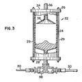
- a metering station 22 is shown in greater detail in Figure 3.
- Figure 3 shows a sectional elevation view of a metering station 22.
- the metering station 22 shown in Figure 3 is representative of each of the metering stations 22a-22d, and each of the reference numerals shown in Figure 3 represents any one of the corresponding components in metering stations 22a-22d.
- the metering station 22 includes a metering canister 24 which is preferably a hollow tube formed from a plastic material, for example, transparent PVC.
- a plastic material for example, transparent PVC.
- the metering canister 24 could be formed from a wide variety of materials, and is not limited to plastic materials or the like.
- the metering canister 24 is capped on its upper end by an upper canister cap 26 and a lower canister cap 28, the caps 26 and 28 pulled into sealing engagement with the canister 24 by canister tie bolts 29.
- the upper canister end 26 is proximate to the corresponding powder hopper 12, and the lower canister end 28 is proximate to an air conveyor line 30 which is utilized to pneumatically convey the powder to a flush bin 32 as further discussed below and as shown in Figure 1 in schematic. That is, as shown in Figure 1, a powdered detergent powder conveyor line 30a is in fluid communication with the corresponding detergent metering canister 24a and so on.
- Upper canister end cap 26 preferably includes female threaded holes which are threadedly engaged by inlet tubes 36.
- the inlet tubes 36 and the end cap 26 are preferably formed from a plastic material, the specific material being a matter of choice within the skill of the art depending on the types of powders being dispensed to the washing machine.
- the inlet tubes 36 are hollow, thus placing the interiors of the metering canisters 24 in fluid communication with the powder hoppers 12 when the corresponding metering valves 14 are in their open states.
- inverted metering funnels 38 are attached to the inlet tubes 36 so that the apex of each funnel 38a-38d is connected to the bottommost portion of the corresponding inlet tube 36.
- the powders are carried by air conveyor lines 30 toward the flush bin 32.
- the conveyor lines 30 preferably combine, in region 31, in a series of "Y's” 46, thereby converging to form a single powder line 44.
- "Y's" 46 to combine several streams of flow to form a single flow line is well known in the art and needs no further description. It should be noted, however, that sharp bends in the conveyor lines 30 and in the "Y's” 46 should be avoided so that powder can be efficiently conveyed to the flush bin 32 without causing a buildup of powder at the sharp bends where the flow might be disturbed.
- an upper flush bin cap 40 forms a pair of apertures to accept the powder line 44 and a solvent supply line 48.
- the powder line 44 preferably extends partially into a flush bin canister 50 and, preferably, an inverted funnel shield 52 is attached to the powder line 44 within the flush bin 32.
- the funnel shield 52 need not necessarily be in the shape of an inverted funnel, this is the preferred shape.
- the solvent supply line 48 also terminates within the flush bin canister 50 proximate to the upper flush bin cap 40. However, as shown in Figure 1, the solvent supply line 48 preferably terminates proximate to the outer surface of the shield 52 whereas the powder line 44 terminates proximate to the inner surface of the shield 52.
- the funnel shield 52 prevents direct contact between the solvent and the termination point of the powder line 44 so as to minimize encrustation of the powder in the termination region of the powder line 44.
- the funnel shield 52 preferably includes an extender skirt 54 which even more effectively prevents the solvent from contacting the termination point of the powder line 44.
- the skirt 54 is preferably in the nature of a circular tube which has a diameter substantially equal to the diameter of the base of the funnel shield 52 and the two are joined so as to form an integral shield.
- the funnel shield 52 along with its extender skirt 54 is preferably formed of a plastic material such as PVC or the like, as is well known to those skilled in the art.
- the flush bin 32 also preferably includes a second inverted funnel 56 which further aids in the elimination of encrustation in the region adjacent to the termination of the powder line 44.
- the second inverted funnel 56 preferably having a smaller included angle than the conical portion of the funnel shield 52, and having a smaller diameter than the skirt 54, is attached at its apex proximate to the termination region of the powder line 44 and proximate to the inner surface of the shield 52 so that the axes of the powder line 44, shield 52 and second inverted funnel 56 are substantially collinear.
- a lower flush bin cap 42 forms an aperture which receives a solution carrying tube 58 which is designed to carry the solution of powder and solvent from the flush bin 32 to a washing container 60 as shown in schematic in Figure 1.
- the powders which are stored in the powder hoppers 12 and metered by the metering stations 22 are pneumatically conveyed in conveyor lines 30 and powder line 44 to the flush bin 32.
- compressed air is used as the conveying medium.
- a compressed air source 62 is connected by an air line 64 to air plenum 66, the air plenum 66 supplying air for the conveyor lines 30 among other things.
- the compressed air source 62 can be in the nature of an air compressor or pump or can be connected to an air line pre-existing in the building in which the washing machine is installed.
- conveyor valves 68 In fluid communication with the air plenum 66 is a plurality of conveyor valves 68 which permit, in their "on" states, air to flow through the conveyor lines 30 so as to launch and convey the powders to the flush bin 32.
- conveyor valve 68a When conveyor valve 68a is turned on, pressurized air is supplied to the detergent conveyor line 30a so as to pick up the powder from the metering station 22a and carry the powder to the powder line 44 and ultimately to the flush bin 32.
- the conveyor valves 68 are connected by valve control lines 70 to the control circuit 18.
- the conveyor valves 68 are preferably solenoid controlled on/off valves but other -types of valves are contemplated by the invention and are well known by those skilled in the art.
- vibrator valves 70 are also in fluid communication with the air plenum 66.
- the vibrator valves 70a permit air to flow through vibrator air lines 72 to pneumatic vibrators 74 mounted on the powder hoppers 12.
- the pneumatic vibrators 74 are well known in the art and include spherical members (not shown) which rapidly move in response to the passage of air through the vibrators 74.
- the vibrators 74 cause the hoppers 12 to vibrate, thus contributing to a more uniform powder flow through the valves 14.
- vibrators 72 could alternatively be electric vibrators of a type well known in the art.
- the vibrator valves 70 are electrically connected to the control circuit 18 by vibrator control lines 76.
- a solvent is supplied through solvent line 48 to flush bin 32 to be mixed with the powder(s).
- the preferred solvent is water as is typically used in most washing machines.
- a water valve 78 preferably a solenoid actuated on/off valve of a type similar to the air conveyor valves 68 discussed above, is electrically connected by water valve line 80 to control circuit 18.
- a pressurized water source 82 supplies water for the flush bin 32 and the water source 82 could be a water pump which is included in the washing machine (not shown), but preferably is pressurized water from the building in which the device 10 is housed.
- control circuit 18 the washing machine (not shown) supplies signals 84 which tell the apparatus 10 when to dispense a powder and what powder to dispense at the appropriate time.
- the control lines 84 operatively connected to the control circuit 18 are for this purpose, control line 84a being for detergent, 84b corresponding to bleach, and so on. It should be noted that the four lines 84a-84d could be replaced by a smaller number of lines that carry encoded information identifying the product to be dispensed.
- Figure 2 schematically illustrates the control circuit 18.
- signal lines run from the control circuit 18 to the metering valves 14, water valve 78, conveyor valves 68, vibrator valves 70, the washing machine (not shown), and the metering valve sense switches as parts of the corresponding metering valves 14.
- the signal lines can be any electrically-conductive paths and are not limited to the precise configuration schematically shown.
- the control circuit 18 includes, in its preferred embodiment, a processing unit 102 and output expanding unit 104 interconnected by signal flow path 103.
- the processing unit 102 and expanding unit 104 receive power from power source 106 through flow paths 108 and 110, respectively.
- digital electronics typically need direct current power at relatively small voltage and current levels.
- the processing unit 102 receives input signals on signal lines 84 from the washing machine (not shown). According to a pre-programmed logic sequence, described below, processing unit 102 provides a coded output signal by means of the flow path 103 to the expanding unit 104.
- the expanding unit 104 comprises a typical digital expander circuit that functions to decode the input signal from flow path 103, providing in response thereto an "expanded" plurality of corresponding output signals suitable for appropriately energizing the various electromechanical components of system 10.
- processing unit 102 includes a Model 8748 microprocessor
- expanding unit 104 includes a Model 8243 output expander, both of which are being sold by Intel Corporation.
- Model 8748 microprocessor includes a central processing unit and program memory, the program memory storing a computer program, discussed below in the "operation" description, which causes the appropriate signals to be placed on flow path 103 in response to signals on lines 84.
- control system 18 could be replaced by any of a large variety of digital logic circuits which function in an analogous fashion to the Intel devices and according to the below described operation thereby. Additionally, the control system could be made up of discrete components which combine to provide the preferred logic flow. Such equivalent circuits are well understood by those skilled in the art in light of the functions which control system 18 preferably performs.
- expanding unit 104 provides: signals on lines 76 to energize vibrator valves 70; signals on lines 70 to activate conveyor valves 68; a signal on line 80 to activate water valve 78; and signals on lines 16 for metering valves 14. It receives its logic select input signals on lines 20 from metering valve sense switches (within metering valves 14) and its logical information input signals from processing unit 102 on path 103.
- the electrical signals to and from units 102 and 104 may need to be filtered, amplified, buffered or otherwise treated in order that they be made compatible with the'units 102 and 104 and compatible with the electromechanical devices which are "driven" by the expanding unit 104.
- the output signals from expanding unit 104 typically do not have adequate power to drive electromechanical devices and may need to be amplified or used to actuate a relay or triac.
- Such amplification devices and circuits are omitted from the drawing for purposes of clarity, but those skilled in the art recognize that they may be needed in some applications.
- Figure 2 is in the nature of a schematic diagram for use by those skilled in the art.
- the operation of the preferred embodiment of the powder dispenser 10 of the present invention is initiated by the washing machine signaling the microprocessor 102 on one of the control lines 84. For example, at the appropriate point in the washing cycle of the washing machine (not shown) the washing machine would appropriately energize line 84a which would be sensed by the microprocessor 102. Upon receiving the signal from the washing machine indicating that detergent is required, the processing unit 102 signals expanding unit 104 which in turn energizes metering valve 14a so that it begins to open.
- Figure 4 shows a flow diagram 120 of a preferred program which controls the functioning of processing unit 102, wherein the referenced diamond 122 and block 124 represent the operative steps discussed above.
- the flow diagram 120 shows the logic flow for a preferred program, and other flow diagrams are contemplated by the present invention. While the flow diagram 120 is not a detailed listing of a computer program, those skilled in the art of computer programming recognize that each "block" of the diagram 120 readily translates directly into, typically, a plurality of statements. Therefore, each block of the flow diagram 120 will not be expressly discussed, but it is recognized that the operation of the system 10 is reflected in the diagram 120.
- the microprocessor 102 energizes vibrator valve 70a (block 128, Figure 4) by signalling expanding unit 104 to place the appropriate signal on vibrator control line 76a. Air flows from the plenum 66 through the vibrator air line 72a to the pneumatic vibrator 74a. The hopper 12a is thereby vibrated so that the detergent within hopper 12a more uniformly flows through metering valve 14a into metering canister 24 through threaded tube 36.
- Detergent continues to fall through tube 36 into metering canister 24 until the uppermost level of the detergent reaches the tube 36, thereby causing the flow of powder to cease.
- the detergent is allowed to fall into the air conveyor line 30a through the bottom of the metering canister 24a. Due to the angle of repose of the powdered material, the material is fairly well constrained within launching T-fitting 98a.
- the launching T-fittings 98 are simply T-shaped fittings which are in fluid communication with the interior of the metering canisters 24, air conveyor lines 30 leading to the air supply and to the flush bin 32.
- the processing unit 102 signals the expanding uni-t 104 to energize the air conveyor valve 68a by means of line 70a so that air flow is conveyed in the air conveyor line 30a.
- Powder detergent which is present in the launching T-fitting 98a is "launched” by the flow of air and pneumatically conveyed along conveyor line 30a to the "T" 46 in the combining region 31 into the powder line 44 and finally into the flush bin 32.
- a feed timer within the processing unit 102 maintains conveyor valve 68a in the open state for a time sufficient to convey all of the detergent from the metering canister 24a to the flush bin 32 (blocks 140 and 142 and diamond 144, Figure 4).
- the amount of time that the feed timer holds the valve 68a in the open state depends on the length of the tubing 30a and the type of powder. For longer lengths of tubing the feed timer must be preset for a longer length of time so that all the powder might be conveyed from the launching T-fitting 98a to the flush bin 32.
- manually actuated input switches can be used to pre-select the feed times for the various substances.
- the water valve timer 78 is initiated substantially at the same time as the conveyor valve 68a (block 146, Figure 4).
- water begins to flow from the water source 82, through the water line 48 and into the flush bin canister 50.
- Powder enters the flush bin 50 through powder line 44 and the powder and water mix in a mixing region 100 within the flush bin canister 50.
- the shield 52 and extension skirt 54 prevent water from coming into direct contact with the tube 44 so as to minimize encrustation of the powdered material in the vicinity of the termination of the powder line 44.
- the funnel 56 also contributes to this effect as the flow of powder destroys any encrustation that begins to bridge across the base of the funnel 56.
- a solution comprising the powder and water is thereby formed and flows through solution carrying tube 58 to the washing container 60.
- the feed time eventually times out (diamond 144, Figure 4) and the water valve 78 and conveyor valve 68a are closed.
- the preset amount of time that is selected for the feed timer is selected based on a variety of factors, including the water pressure, air pressure, and type of powder, among other things.
- the valves 68a and 78 are closed (block 148, Figure 4) and the control system is again placed in a ready state awaiting the next signal from the washing machine (not shown) on one of the signal lines 84.
- the processing unit 102 could immediately proceed to the dispensing of another powder from another one of the hoppers 12b through 12d. That is, the processing unit 102 could be programmed to immediately dispense another powder following the dispensing of powdered detergent from hopper 12a. It should be noted that the logic flow as illustrated in Figure 4 is preferably utilized for the dispensing of all of the powdered products, with only the timers being subject to change.
- processing unit 102 can be replaced by a plurality of discrete components, relays, integrated circuits or other types of circuits which supply the preferred logic.
- the logic is quite straight-forward, as illustrated in Figure 4, and well within the skill of the ordinary artisan.
Abstract
An apparatus and method for dispensing a powder to a washing container (60) within a washing machine. A preferred embodiment (10) of the apparatus includes a plurality of powder hoppers (12) which store, for example, powdered detergent, bleach, softener and sour. Valves (14) selectively permit the powdered products to flow from the hoppers (12) to metering canisters (22), the canisters (22) metering from the hoppers (12) predetermined amounts of the products. At various times in the washing machine's cycle the powdered products are pnuematically launched and conveyed to a flush bin (32) where the products are mixed with water to form a solution. The resulting solution is carried from the flush bin (32) to the washing container (60) within the washing machine.
Description
- This invention relates to powder dispensers for washing machines and more particularly to a dispensing method and apparatus for dispensing dry detergents, bleaches and the like to washing machines.
- Many washing machines are capable of using powdered detergents, bleaches, water softeners and pH adjusters (sours). Widespread use of these powdered materials in washing machines has been hindered by several problems, however. Among the problems is the inability to precisely manually premeasure the appropriate amount of powdered product for the washing machine. Additionally, many machines are unable to automatically dispense such powdered materials to the washing container of the washing machine at the appropriate time(s) during the processing cycles.
- Another long-standing problem with the use of powdered detergents and the like is related to the inherent hygroscopic characteristic of most dry detergents. This property often results in premature wetting of portions of the detergent and the formation of a crust which prevents the dispensing apparatus from functioning properly and accurately.
- Several approaches to the problem of automatically dispensing a powdered product to a washing machine have been tried. One type of powder dispenser system requires that the user manually premeasure the appropriate amount of powdered detergent and pour this premeasured amount of detergent into a flush bin. At the appropriate time during the washing machine's processing cycle, water is forced through the flush bin to hydraulically convey the powdered product to the washing container within the washing machine. Clearly, this type of powder dispenser system suffers from several shortcomings. The user must remember to add detergent prior to each cycle of the washing machine; the user must accurately measure the appropriate amount of powdered product prior to the machine's cycle; the powder has a tendency to form a crust or cake. as it sits stationary in the flush bin prior to actually being flushed through the system and into the washing container; and such powder dispensing systems are primarily useful for powdered detergents, alone, the dispensing systems having only one flush bin.
- Another approach to the powder dispensing problem involves a relatively large powder hopper in which a large first amount of powdered detergent is stored. The dispensing system automatically meters out a second smaller amount of detergent from the hopper and pneumatically conveys this second amount directly to the washing container. Thus, this approach to the problem does not contemplate the use of a flush bin from which the powdered product is hydraulically flushed.
- It is perceived that this type of dispensing system also possesses several shortcomings. Importantly, such systems are not adjustable. That is, the "measuring station" which meters the smaller second amount of powder from the larger first amount stored in the hopper is not adjustable. Therefore, such systems are only compatible with one type of powder and one type of machine.
- Furthermore, such dispensing systems include only one hopper so that only one powdered product can be dispensed to the washing container during a given machine cycle.
- Finally, since the powder is directly dumped into the washing container, the exit end or outlet end of the powder tube is in direct fluid communication with the washing container. This results in relatively uncontrolled mixing conditions and also results potentially in water spray from the washing container coming into contact with the end of the powder tube, thereby contributing to the encrustation of powder in the vicinity of the end of the tube, eventually occluding the end of the powder tube to some degree.
- Still other types of powder dispensers do not include means for metering the powder independent from the conveying means. That is, the powder is pneumatically conveyed to the washing container directly from the main hopper and the amount conveyed to the washing container depends on the flow rate of the air, the type of powder and the amount of time that the air flow is present.
- Such pneumatic powder dispensing systems suffer if the air flow varies due to problems with the fan, partial plugging of the line or variations in the powdered products. Also, if the period of time during which the fan is "on" is not accurately and repeatably controlled, the amount of powder delivered to the washing container will vary from cycle to cycle. Additionally, such systems are usually not adjustable to compensate for variations in the physical properties of the powdered products and changes in the length of tubing. Such changes should require longer or shorter fan "on" times and/or flow rates to convey the same amount of powder to the container.
- Still another type of conveying system in the prior art includes moving parts, for example brushes in contact with a screen, which directly and mechanically convey the powder through the system. It is perceived that such systems are prone to clog and maintenance of the equipment is likely to be required on a regular basis to prevent the build-up of powder.
- The present invention is directed to the shortcomings of 'the prior art powder dispensing systems discussed above. More particularly, the present invention is a method and apparatus for dispensing a powdered product to the washing container of a washing machine. The apparatus of the present invention includes a metering station which meters a second amount of powdered product from a larger first amount stored in a hopper. Following the metering operation, the second amount of powder is pneumatically conveyed to a flush bin where the powder is dynamically mixed with a solvent and the resultant solution is carried to the washing container. Thus, the user need not accurately measure the amount of powder required for the machine. Furthermore, caking of the powdered product is minimized because of the feature of dynamic mixing of the solvent and the powder in a flush bin wherein, preferably, a shield prevents the solvent from coming into direct contact with the outlet of the powder tube. The mixing takes place in a controlled environment independent from the conditions within the washing container which might vary from cycle to cycle or from subcycle to subcycle depending on the machine.
- The apparatus of the present invention includes means for metering the second smaller amount of powdered product separate from the conveying means so that the pneumatic conveying process does not directly impact the amount of powder conveyed. That is, the metering process itself determines the second amount of powder and the conveying means simply conveys the metered amount of powder to the flush bin.
- The invention also includes a method for dispensing a powder to a washing container. The method is also directed to the shortcomings of the prior art devices and generally includes the steps of metering and conveying the powder, mixing the powder with a solvent and finally carrying the resulting solution to the washing container.
- The present invention includes a system for dispensing a powder to a washing machine, the powder being mixed with a solvent to produce a solution for use in a washing container of the washing machine. The dispensing system includes means for storing a first quantity of the powder; means for - pneumatically launching a second quantity less than the first quantity of the powder; means for mixing the second quantity of the powder and the solvent to produce the solution; means in fluid communication with the mixing means for supplying the solvent to the mixing means; means in fluid communication with the storing means and the launching means for metering the second quantity of the powder to the launching means; means in the fluid communication with the launching means and the mixing means for pneumatically conveying the second quantity of the powder from the launching means to the mixing means; and means in fluid communication with the mixing means and the washing container for carrying the solution from the mixing means to the washing container.
- In a preferred embodiment of the apparatus of the present invention the metering means of the dispensing system includes a metering canister in fluid communication with the launching means; a metering valve in fluid communication with the storing means and the metering canister; and means for controlling the metering valve, wherein the metering valve controlling means causes the metering valve to open for a metering time period sufficient to allow a flow of the powder for a powder flow time period wherein the second quantity of the powder flows from the storing means into the metering canister, and wherein following the metering time period the metering valve control means causes the metering valve to close.
- The metering canister of a preferred dispensing system includes an upper end and a lower end and the metering canister forms an inlet port in fluid communication with the metering valve proximate to the upper end and an outlet port in fluid communication with the launching means proximate to the lower end, the inlet port accommodating the flow of powder wherein the metering canister is progressively filled with the powder during the metering time period so that an uppermost level of the powder moves progressively toward the inlet port, wherein the flow of the powder through the inlet port substantially ceases when the uppermost level of the powder reaches the inlet port, and wherein the metering time period exceeds the powder flow time period.
- Furthermore, in a preferred embodiment of the apparatus of the present invention, a. metering canister distance between the inlet port of the metering canister and the lower end of the canister is adjustable, whereby the second quantity of powder can be increased by increasing the metering canister distance and the second quantity of the powder can be decreased by decreasing the metering canister distance.
- In another preferred embodiment of the apparatus of the present invention, the metering canister forms a threaded opening in its upper end and the inlet port includes a threaded tube wherein the threaded tube and the threaded opening engage so that adjustment of the metering canister distance is effected by rotating the threaded tube with respect to the threaded opening in the upper end of the metering canister.
- In still another preferred embodiment of the apparatus of the present invention, the mixing means includes a mixing canister in fluid communication with the supplying means and the conveying means. In this embodiment, the mixing canister includes an upper end and a lower end and the mixing canister forms a powder inlet in fluid communication with the conveying means and a solvent inlet in fluid communication with the supplying means, the inlets being proximate to the upper end of the mixing canister. This embodiment further includes a shielding means between the powder inlet and the solvent inlet to prevent the solvent from coming into direct contact with the powder inlet to minimize the caking of the powder proximate to the powder inlet. Finally, this embodiment includes a mixing canister outlet proximate to the mixing canister lower end.
- In one embodiment, the shielding means includes an inverted frusto-conical member which is axially aligned with the mixing canister powder inlet. The frusto-conical member has an inner surface proximate to the powder inlet and an outer surface proximate to the solvent inlet. The apex of the frusto-conical member is disposed so as to be proximate to the upper end of the mixing canister and the circular base of the frusto-conical member has a diameter less than the inside diameter of the mixing canister so that solvent can flow around the shield and into a mixing region where the solvent and the powder mix to form the solution.
- The present invention also includes a method for dispensing a powder to a washing machine. The powder is mixed with a solvent to produce a solution for use in a washing container of the washing machine, and the dispensing method includes storing a first quantity of the powder in a storage region; metering from the first quantity of the powder to a launching region a second quantity of the powder less than the first quantity of the powder; pneumatically launching the second quantity of powder in the launching region and conveying the second quantity of the powder to a mixing region; supplying the solvent to the mixing region; mixing the second quantity of the powder and the solvent in the mixing region to produce the solution; and carrying the solution from the mixing region to the washing container. The metering step of a preferred method includes opening fluid communication between the storage region and the launching region for a metering time period to allow a flow of the powder for a powder flow time period; and closing fluid communication between the storage region and the launching region following the metering time period.
- The metering step of still another preferred embodiment includes ceasing the flow of the powder at the expiration of the powder flow time period when the second quantity of the powder has accumulated in a launching region, the powder flow time period being less than the metering time period.
- A preferred method is further characterized in that the second quantity of the powder is adjustable.
- A preferred method is characterized in that the second quantity of the powder enters the mixing region through a mixing region powder inlet and the solvent enters the mixing region through a mixing region solvent inlet. The mixing step includes shielding the mixing region powder inlet from the mixing region solvent inlet, wherein the solvent is prevented from directly contacting the mixing region powder inlet to minimize the encrustation of powder proximate to the mixing region powder inlet.
- A preferred method is further characterized in that the shielding includes shielding with an inverted frusto-conical member axially aligned with the mixing region powder inlet. The apex of the frusto-conical member is proximate to the mixing region inlets, an outer surface of the member is proximate to the solvent inlet and the inner surface of the member is proximate to the powder inlet.
- While the specification concludes with claims particularly pointing out and distinctly claiming the subject matter which is regarded as the present invention, it is believed that the invention will be better understood from the following description taken in connection with the accompanying drawing in which:
- Figure 1 shows a schematic of the powder dispensing system of the present invention.
- Figure 2 shows a schematic of the electrical control system of the powder dispensing system shown in Figure 1.
- Figure 3 shows a side elevational cross-section of the powder measuring station of the dispensing system shown in Figure 1.
- Figure 4 shows a flow diagram of a computer program useful in conjuction with the control system illustrated in Figures 1 and 2.
- In the following description of the invention like reference numerals represent like components, elements, subsystems and systems throughout the several views. Furthermore, although the detailed description focuses on a preferred apparatus and method, the present invention is not so limited.
- Figure 1 shows a schematic view of a powder dispensing apparatus of the present invention, generally designated with the
reference numeral 10. The powder dispensing apparatus 1U is t'or dispensing a powdered soap or the like to a washing machine (not shown). The phrases "powdered soap," "soap powder" and the like are meant to include detergents, true soaps, water conditioners and softeners, and combinations of such substances which may be useful in the washing of fabrics or dish ware, for example. "Powders" or "powdered substances," as used herein, are in the form of discrete particles or solids, be such powder, granules, flakes, pieces, or otherwise. Furthermore, the phrase "washing machine" is meant to include all machines in which an operation occurs or wherein a "powder" is mixed with a solvent and the resulting mixture is used for the treatment of various articles such as fabrics or dishware. - Thus, the dispensing
apparatus 10 of the present invention functions to mix a powder with a "solvent" to form a mixture for use in a washing machine. The term "solvent" is meant to include any liquid used in washing machines and the resulting mixture or solution is meant to include all mixtures of powders and solvents in washing machines. That is, the terms solvent and solution are not limited to their strict chemical definitions wherein a solute is completely dissolved in a solvent to form a solution. Herein, the solute, the powder which is to be dispensed to the washing machine, is mixed with the solvent but does not necessarily dissolve in the solvent in the strict sense of the word. The resulting solution, although perhaps not, strictly speaking, a solution per se, is conveyed or carried to awashing container 60 of the washing machine for use in a washing or treating process. - The
powder dispensing apparatus 10 includespowder hoppers detergent powder hopper 12a, ableach powder hopper 12b, a sour powder hopper 12c and a softener powder hopper 12d. Detergent, bleach, sour and softener are common powdered substances used in washing machines, as well known to those skilled in the art of washing machine use and design. As is well known, "sour" is a substance which is used to adjust the pH of the solution being utilized in thewashing container 60 of the washing machine, and "softener" is a substance which reduces the effects of static electricity in the fabrics which are treated within the washing machine. - The
powder dispensing apparatus 10 further includes, in fluid communication and preferably below the powder hoppers 12,metering valves 14. Each of the powder hoppers 12 includes acorresponding metering valve 14. Therefore, there is adetergent metering valve 14a, ableach metering valve 14b, asour metering valve 14c and asoftener metering valve 14d. Preferably, themetering valves 14 are of the ball valve type and are electrically operated. Clearly, as is evident to one skilled in the art, the metering valves could be any type of on/off valve powered in any conventional fashion. - Preferably, the
metering valves 14 are electrically operated and, in the preferred embodiment shown in schematic in Figure 1, themetering valves 14 are connected by electrically-conductivevalve control lines 16a through 16d to acontrol circuit 18. Thecontrol circuit 18 is shown in schematic in Figure 2 and will be discussed in more detail below. - Also connected to the
metering valves 14 are valve sense lines 20. Thevalve sense lines control circuit 18 and their function is also described below particularly with reference to Figure 2. - In fluid communication with the
metering valves 14a-14d are metering stations 22a-22d, respectively. Thus, in fluid communication withdetergent metering valve 14a is a detergent metering station 22a and so on. Ametering station 22 is shown in greater detail in Figure 3. - As mentioned above, Figure 3 shows a sectional elevation view of a
metering station 22. Themetering station 22 shown in Figure 3 is representative of each of the metering stations 22a-22d, and each of the reference numerals shown in Figure 3 represents any one of the corresponding components in metering stations 22a-22d. - The
metering station 22 includes ametering canister 24 which is preferably a hollow tube formed from a plastic material, for example, transparent PVC. As is clear to those skilled in the art, themetering canister 24 could be formed from a wide variety of materials, and is not limited to plastic materials or the like. - The
metering canister 24 is capped on its upper end by anupper canister cap 26 and alower canister cap 28, thecaps canister 24 bycanister tie bolts 29. - Preferably, the
upper canister end 26 is proximate to the corresponding powder hopper 12, and thelower canister end 28 is proximate to anair conveyor line 30 which is utilized to pneumatically convey the powder to a flush bin 32 as further discussed below and as shown in Figure 1 in schematic. That is, as shown in Figure 1, a powdered detergentpowder conveyor line 30a is in fluid communication with the corresponding detergent metering canister 24a and so on. - Upper
canister end cap 26 preferably includes female threaded holes which are threadedly engaged byinlet tubes 36. Theinlet tubes 36 and theend cap 26 are preferably formed from a plastic material, the specific material being a matter of choice within the skill of the art depending on the types of powders being dispensed to the washing machine. Theinlet tubes 36 are hollow, thus placing the interiors of themetering canisters 24 in fluid communication with the powder hoppers 12 when the correspondingmetering valves 14 are in their open states. - Preferably, inverted metering funnels 38 are attached to the
inlet tubes 36 so that the apex of each funnel 38a-38d is connected to the bottommost portion of thecorresponding inlet tube 36. - It can be seen that rotation of the
inlet tube 36 about its axis relative to the corresponding uppercanister end cap 26 causes theinlet tube 36 and correspondinginverted metering funnel 38 to advance toward or retract from thelower canister end 28. This operation adjusts the amount of powder which is conveyed to the flush bin 32 and ultimately carried to the washing container of the washing machine. The adjustment process is discussed in greater detail below. - As mentioned above, the powders are carried by
air conveyor lines 30 toward the flush bin 32. Actually, theconveyor lines 30 preferably combine, inregion 31, in a series of "Y's" 46, thereby converging to form a single powder line 44. The use of "Y's" 46 to combine several streams of flow to form a single flow line is well known in the art and needs no further description. It should be noted, however, that sharp bends in theconveyor lines 30 and in the "Y's" 46 should be avoided so that powder can be efficiently conveyed to the flush bin 32 without causing a buildup of powder at the sharp bends where the flow might be disturbed. - Turning again to Figure 1, an upper flush bin cap 40 forms a pair of apertures to accept the powder line 44 and a
solvent supply line 48. The powder line 44 preferably extends partially into aflush bin canister 50 and, preferably, aninverted funnel shield 52 is attached to the powder line 44 within the flush bin 32. Although thefunnel shield 52 need not necessarily be in the shape of an inverted funnel, this is the preferred shape. Thesolvent supply line 48 also terminates within theflush bin canister 50 proximate to the upper flush bin cap 40. However, as shown in Figure 1, thesolvent supply line 48 preferably terminates proximate to the outer surface of theshield 52 whereas the powder line 44 terminates proximate to the inner surface of theshield 52. Thefunnel shield 52 prevents direct contact between the solvent and the termination point of the powder line 44 so as to minimize encrustation of the powder in the termination region of the powder line 44. - The
funnel shield 52 preferably includes an extender skirt 54 which even more effectively prevents the solvent from contacting the termination point of the powder line 44. The skirt 54 is preferably in the nature of a circular tube which has a diameter substantially equal to the diameter of the base of thefunnel shield 52 and the two are joined so as to form an integral shield. Thefunnel shield 52 along with its extender skirt 54 is preferably formed of a plastic material such as PVC or the like, as is well known to those skilled in the art. - The flush bin 32 also preferably includes a second
inverted funnel 56 which further aids in the elimination of encrustation in the region adjacent to the termination of the powder line 44. The secondinverted funnel 56, preferably having a smaller included angle than the conical portion of thefunnel shield 52, and having a smaller diameter than the skirt 54, is attached at its apex proximate to the termination region of the powder line 44 and proximate to the inner surface of theshield 52 so that the axes of the powder line 44,shield 52 and secondinverted funnel 56 are substantially collinear. - Finally, a lower
flush bin cap 42 forms an aperture which receives asolution carrying tube 58 which is designed to carry the solution of powder and solvent from the flush bin 32 to awashing container 60 as shown in schematic in Figure 1. - The powders which are stored in the powder hoppers 12 and metered by the
metering stations 22 are pneumatically conveyed inconveyor lines 30 and powder line 44 to the flush bin 32. Preferably, compressed air is used as the conveying medium. A compressed air source 62 is connected by an air line 64 toair plenum 66, theair plenum 66 supplying air for theconveyor lines 30 among other things. - As well known to those skilled in the art, the compressed air source 62 can be in the nature of an air compressor or pump or can be connected to an air line pre-existing in the building in which the washing machine is installed.
- In fluid communication with the
air plenum 66 is a plurality ofconveyor valves 68 which permit, in their "on" states, air to flow through theconveyor lines 30 so as to launch and convey the powders to the flush bin 32. Thus, when conveyor valve 68a is turned on, pressurized air is supplied to thedetergent conveyor line 30a so as to pick up the powder from the metering station 22a and carry the powder to the powder line 44 and ultimately to the flush bin 32. - The
conveyor valves 68 are connected byvalve control lines 70 to thecontrol circuit 18. Theconveyor valves 68 are preferably solenoid controlled on/off valves but other -types of valves are contemplated by the invention and are well known by those skilled in the art. - Also in fluid communication with the
air plenum 66 arevibrator valves 70. Thevibrator valves 70a permit air to flow through vibrator air lines 72 to pneumatic vibrators 74 mounted on the powder hoppers 12. The pneumatic vibrators 74 are well known in the art and include spherical members (not shown) which rapidly move in response to the passage of air through the vibrators 74. The vibrators 74 cause the hoppers 12 to vibrate, thus contributing to a more uniform powder flow through thevalves 14. It should be noted that vibrators 72 could alternatively be electric vibrators of a type well known in the art. - Preferably, the
vibrator valves 70 are electrically connected to thecontrol circuit 18 by vibrator control lines 76. - As mentioned above with reference to Figure 1, a solvent is supplied through
solvent line 48 to flush bin 32 to be mixed with the powder(s). It should be noted that the preferred solvent is water as is typically used in most washing machines. Awater valve 78, preferably a solenoid actuated on/off valve of a type similar to theair conveyor valves 68 discussed above, is electrically connected bywater valve line 80 to controlcircuit 18. Apressurized water source 82 supplies water for the flush bin 32 and thewater source 82 could be a water pump which is included in the washing machine (not shown), but preferably is pressurized water from the building in which thedevice 10 is housed. - Finally, with respect to control
circuit 18, the washing machine (not shown) supplies signals 84 which tell theapparatus 10 when to dispense a powder and what powder to dispense at the appropriate time. The control lines 84 operatively connected to thecontrol circuit 18 are for this purpose,control line 84a being for detergent, 84b corresponding to bleach, and so on. It should be noted that the fourlines 84a-84d could be replaced by a smaller number of lines that carry encoded information identifying the product to be dispensed. - Figure 2 schematically illustrates the
control circuit 18. As substantially described above, signal lines run from thecontrol circuit 18 to themetering valves 14,water valve 78,conveyor valves 68,vibrator valves 70, the washing machine (not shown), and the metering valve sense switches as parts of the correspondingmetering valves 14. As clear to those skilled in the art, the signal lines can be any electrically-conductive paths and are not limited to the precise configuration schematically shown. - The
control circuit 18 includes, in its preferred embodiment, aprocessing unit 102 andoutput expanding unit 104 interconnected bysignal flow path 103. Theprocessing unit 102 and expandingunit 104 receive power frompower source 106 through flow paths 108 and 110, respectively. As well known to those skilled in the art, digital electronics typically need direct current power at relatively small voltage and current levels. - The
processing unit 102 receives input signals on signal lines 84 from the washing machine (not shown). According to a pre-programmed logic sequence, described below, processingunit 102 provides a coded output signal by means of theflow path 103 to the expandingunit 104. The expandingunit 104, as well known to those skilled in the art, comprises a typical digital expander circuit that functions to decode the input signal fromflow path 103, providing in response thereto an "expanded" plurality of corresponding output signals suitable for appropriately energizing the various electromechanical components ofsystem 10. In the preferred embodiment, processingunit 102 includes a Model 8748 microprocessor, and expandingunit 104 includes a Model 8243 output expander, both of which are being sold by Intel Corporation. It should be noted that the Model 8748 microprocessor includes a central processing unit and program memory, the program memory storing a computer program, discussed below in the "operation" description, which causes the appropriate signals to be placed onflow path 103 in response to signals on lines 84. - As well known to those skilled in the art, the above- described processor and expander networks could be replaced by any of a large variety of digital logic circuits which function in an analogous fashion to the Intel devices and according to the below described operation thereby. Additionally, the control system could be made up of discrete components which combine to provide the preferred logic flow. Such equivalent circuits are well understood by those skilled in the art in light of the functions which control
system 18 preferably performs. - As shown in Figure 2, expanding
unit 104 provides: signals on lines 76 to energizevibrator valves 70; signals onlines 70 to activateconveyor valves 68; a signal online 80 to activatewater valve 78; and signals on lines 16 formetering valves 14. It receives its logic select input signals on lines 20 from metering valve sense switches (within metering valves 14) and its logical information input signals from processingunit 102 onpath 103. - It should be noted that the electrical signals to and from
units the'units unit 104. For example, as well known to those skilled in the art, the output signals from expandingunit 104 typically do not have adequate power to drive electromechanical devices and may need to be amplified or used to actuate a relay or triac. Such amplification devices and circuits are omitted from the drawing for purposes of clarity, but those skilled in the art recognize that they may be needed in some applications. Thus, Figure 2 is in the nature of a schematic diagram for use by those skilled in the art. - The operation of the preferred embodiment of the
powder dispenser 10 of the present invention is initiated by the washing machine signaling themicroprocessor 102 on one of the control lines 84. For example, at the appropriate point in the washing cycle of the washing machine (not shown) the washing machine would appropriately energizeline 84a which would be sensed by themicroprocessor 102. Upon receiving the signal from the washing machine indicating that detergent is required, theprocessing unit 102signals expanding unit 104 which in turn energizesmetering valve 14a so that it begins to open. - Figure 4 shows a flow diagram 120 of a preferred program which controls the functioning of
processing unit 102, wherein the referenceddiamond 122 and block 124 represent the operative steps discussed above. The flow diagram 120 shows the logic flow for a preferred program, and other flow diagrams are contemplated by the present invention. While the flow diagram 120 is not a detailed listing of a computer program, those skilled in the art of computer programming recognize that each "block" of the diagram 120 readily translates directly into, typically, a plurality of statements. Therefore, each block of the flow diagram 120 will not be expressly discussed, but it is recognized that the operation of thesystem 10 is reflected in the diagram 120. - Once the
metering valve 14a is completely open, as sensed by a change in electrical state onvalve sense line 20a (diamond 126, Figure 4), themicroprocessor 102 energizesvibrator valve 70a (block 128, Figure 4) by signalling expandingunit 104 to place the appropriate signal onvibrator control line 76a. Air flows from theplenum 66 through thevibrator air line 72a to the pneumatic vibrator 74a. Thehopper 12a is thereby vibrated so that the detergent withinhopper 12a more uniformly flows throughmetering valve 14a intometering canister 24 through threadedtube 36. - Detergent continues to fall through
tube 36 intometering canister 24 until the uppermost level of the detergent reaches thetube 36, thereby causing the flow of powder to cease. - It should be noted, as shown in Figure 3, that the detergent is allowed to fall into the
air conveyor line 30a through the bottom of the metering canister 24a. Due to the angle of repose of the powdered material, the material is fairly well constrained within launching T-fitting 98a. The launching T-fittings 98 are simply T-shaped fittings which are in fluid communication with the interior of themetering canisters 24,air conveyor lines 30 leading to the air supply and to the flush bin 32. - As noted above, once the level of the powdered detergent reaches the tube 36a, the flow of powdered detergent into the metering canister 24a ceases, but the
metering valve 14a remains in its open state. Finally, once a metering time period has expired (block 130 anddiamond 132, Figure 4), thevibrator valve 70a is closed (block 134, Figure 4) so as to stop the vibration of pneumatic vibrator 74a and themetering valve 14a is signalled byvalve line 16a to begin the closing process (block 136, Figure 4). Once themetering valve 14a is completely closed, as indicated by the state of meteringvalve sense line 20a (diamond 138, Figure 4), theprocessing unit 102 signals the expanding uni-t 104 to energize the air conveyor valve 68a by means ofline 70a so that air flow is conveyed in theair conveyor line 30a. Powder detergent which is present in the launching T-fitting 98a is "launched" by the flow of air and pneumatically conveyed alongconveyor line 30a to the "T" 46 in the combiningregion 31 into the powder line 44 and finally into the flush bin 32. A feed timer within theprocessing unit 102 maintains conveyor valve 68a in the open state for a time sufficient to convey all of the detergent from the metering canister 24a to the flush bin 32 (blocks diamond 144, Figure 4). The amount of time that the feed timer holds the valve 68a in the open state depends on the length of thetubing 30a and the type of powder. For longer lengths of tubing the feed timer must be preset for a longer length of time so that all the powder might be conveyed from the launching T-fitting 98a to the flush bin 32. Although not shown in Figure 2, manually actuated input switches can be used to pre-select the feed times for the various substances. - Preferably, the
water valve timer 78 is initiated substantially at the same time as the conveyor valve 68a (block 146, Figure 4). Thus, water begins to flow from thewater source 82, through thewater line 48 and into theflush bin canister 50. Powder enters theflush bin 50 through powder line 44 and the powder and water mix in amixing region 100 within theflush bin canister 50. Theshield 52 and extension skirt 54 prevent water from coming into direct contact with the tube 44 so as to minimize encrustation of the powdered material in the vicinity of the termination of the powder line 44. Thefunnel 56 also contributes to this effect as the flow of powder destroys any encrustation that begins to bridge across the base of thefunnel 56. - A solution comprising the powder and water is thereby formed and flows through
solution carrying tube 58 to thewashing container 60. The feed time eventually times out (diamond 144, Figure 4) and thewater valve 78 and conveyor valve 68a are closed. The preset amount of time that is selected for the feed timer is selected based on a variety of factors, including the water pressure, air pressure, and type of powder, among other things. - Once the feed timer has elapsed, the
valves 68a and 78 are closed (block 148, Figure 4) and the control system is again placed in a ready state awaiting the next signal from the washing machine (not shown) on one of the signal lines 84. Alternatively, theprocessing unit 102 could immediately proceed to the dispensing of another powder from another one of thehoppers 12b through 12d. That is, theprocessing unit 102 could be programmed to immediately dispense another powder following the dispensing of powdered detergent fromhopper 12a. It should be noted that the logic flow as illustrated in Figure 4 is preferably utilized for the dispensing of all of the powdered products, with only the timers being subject to change. - Those skilled in the art will recognize that the
processing unit 102 can be replaced by a plurality of discrete components, relays, integrated circuits or other types of circuits which supply the preferred logic. The logic is quite straight-forward, as illustrated in Figure 4, and well within the skill of the ordinary artisan. - Modifications of the invention will be apparent to those skilled in the art in light of the foregoing description. This description is intended to provide specific examples of individual embodiments which clearly disclose the present invention. Accordingly, the invention is not limited to these embodiments or to the use of elements having specific configurations and shapes as presented herein. All alternative modifications and variations of the present invention which follow in the spirit and broad scope of the appended claims are included.
Claims (16)
1. A system for dispensing a powder to a washing machine, the powder being mixed with a solvent to produce a solution for use in a washing container of the washing machine, the dispensing system comprising:
(a) means for storing a first quantity of the powder;
(b) means for pneumatically launching a second quantity of the powder less than said first quantity of the powder;
(c) means for mixing said second quantity of the powder and the solvent to produce the solution;
(d) means in fluid communication with said mixing means for supplying the solvent to said mixing means;
(e) means in fluid communication with said storing means and said launching means for metering said second quantity of the powder to said launching means;
(f) means in fluid communication with said launching means and said mixing means for pneumatically conveying said second quantity of the powder from said launching means to said mixing means; and
(g) means in fluid communication with said mixing means and the washing container for carrying the solution from said mixing means to the washing container.
2. The dispensing system according to Claim 1, wherein said metering means comprises:
(a) a metering canister in fluid communication with said launching means;
(b) a metering valve in fluid communication with said storing means and said metering canister; and
(c) means for controlling said metering valve, wherein said metering valve controlling means causes said metering valve to open for a metering time period sufficient to allow a flow of the powder for a powder flow time period wherein said second quantity of the powder flows from said storing means into said metering canister, and wherein following said metering time period said metering valve controlling means causes said metering valve to close.
3. The dispensing system according to Claim 2, wherein said metering canister comprises an upper end and a lower end and said metering canister forms an inlet port in fluid communication with said metering valve proximate to said upper end and an outlet port in fluid communication with said launching means proximate to said lower end, said inlet port accommodating said flow of the powder wherein said metering canister is progressively filled with the powder during said metering time period so that an uppermost level of the powder moves progressively toward said inlet port, wherein said flow of the powder through said inlet port substantially ceases when said uppermost level of the powder reaches said inlet port, and wherein said metering time period exceeds said powder flow time period.
4. The dispensing system according to Claim 3, wherein a metering canister distance between said inlet port of said metering canister and said lower end of said canister is adjustable, whereby said second quantity of the powder can be increased by increasing said metering canister distance and said second quantity of the powder can be decreased by decreasing said metering canister distance.
5. The dispensing system according to Claim 4, wherein said metering canister forms a threaded opening proximate to said upper end of said metering canister, and said inlet port comprises a threaded tube, wherein said threaded tube and said threaded opening threadedly engage, and wherein adjustment of said metering canister distance is effected by axially rotating said threaded tube relative to said threaded opening.
6. The dispensing system according to Claim 1, wherein said mixing means comprises:
(a) a mixing canister in fluid communication with said supplying means and said conveying means, said mixing canister including a mixing canister upper end and a mixing canister lower end, and said mixing canister forming a mixing canister powder inlet in fluid communication with said conveying means and a mixing canister solvent inlet in fluid communication with said supplying means, said mixing canister inlets being proximate to said mixing canister upper end;
(b) means disposed between said mixing canister inlets for shielding said mixing canister powder inlet, said shielding means substantially preventing the solvent from coming into contact with said mixing canister powder inlet; and
(c) a mixing canister outlet formed by said mixing canister, said mixing canister outlet being proximate to said mixing canister lower end, whereby said shielding means minimizes caking of the powder proximate to said mixing canister powder inlet.
7. The dispensing system according to Claim 6, wherein said mixing canister has a canister inside diameter and said shielding means comprises an inverted frusto-conical member axially aligned with said mixing canister powder inlet, said frusto-conical member having an inner surface, an outer surface, a substantially circular base and an apex, said mixing canister powder inlet being proximate to said inner surface and said mixing canister solvent inlet being proximate to said outer surface, and said circular base having a base diameter less than said canister inside diameter, wherein the solvent is directed to flow proximate said outer surface, the powder is directed to flow proximate said inner surface, and the powder and solvent mix in a mixing region below said circular base of said frusto-conical member.
8. The dispensing system according to Claim 5, wherein said mixing means comprises:
(a) a mixing canister in fluid communication with said supplying means and said conveying means, said mixing canister including a mixing canister upper end and a mixing canister lower end, and said mixing canister forming a mixing canister powder inlet in fluid communication with said conveying means and a mixing canister solvent inlet in fluid communication with said supplying means, said mixing canister inlets being proximate to said mixing canister upper end;
(b) means disposed between said mixing canister inlets for shielding said mixing canister powder inlet, said shielding means substantially preventing the solvent from coming into contact with said mixing canister powder inlet; and
(c) a mixing canister outlet formed by said mixing canister, said mixing canister outlet being proximate to said mixing canister means, whereby said shielding means minimizes caking of the powder proximate to said mixing canister powder inlet.
9. The dispensing system according to Claim 8, wherein said mixing canister has a canister inside diameter and said shielding mean's comprises an inverted frusto-conical member axially aligned with said mixing canister powder inlet, said frusto-conical member having an inner surface, an outer surface, a substantially circular base and an apex, said mixing canister powder inlet being proximate to said inner surface and said mixing canister solvent inlet being proximate to said outer surface, and said circular base having a base diameter less than said canister inside diameter, wherein the solvent is directed to flow proximate said outer surface, the powder is directed to flow proximate said inner surface, and the powder and solvent mix in a mixing region below said circular base of said frusto-conical member.
10. A system for dispensing a powder to a washing machine, the powder being mixed with a quantity of water to produce a solution for use in a washing container of the washing machine, the dispensing system comprising:
powder shield disposed between said powder and water ports;
. (a) a frusto-conical hopper for storing a first quantity of the powder;
(b) a T-fitting for pneumatically launching a second quantity of the powder less than said first quantity of the powder, said T-fitting forming first, second and third ports;
(c) an air compressor in fluid communication with said first port of said T-fitting;
(d) a mixing canister for mixing the quantity of water and said second quantity of the powder to produce the solution, said mixing canister forming a powder port, a water port and an outlet port and including a
powder shield disposed between said powder and water ports;
(e) a pressurized water source in fluid communication with said mixing canister for supplying the quantity of water to said water port of said mixing canister;
(f) a metering canister in fluid communication with said hopper and said second port of said T-fitting for adjustably metering said second quantity of the powder to said T-fitting, said metering canister including an upper end and a lower end and said metering canister forming an inlet port in fluid communication with said hopper proximate to said upper end and an outlet port in fluid communication with said T-fitting proximate to said lower end, wherein said second quantity of the powder is determined by a distance between said inlet port and said lower end, said distance being adjustable;
(g) a first tube in fluid communication with said third port of said T-fitting and said powder port of said mixing canister for pneumatically conveying said second quantity of the powder from said T-fitting to said mixing canister; and
(h) a second tube in fluid communication with said outlet port of said mixing canister and the washing container for carrying the solution from said mixing canister to the washing container.
11. A method for dispensing a powder to a washing machine, the powder being mixed with a solvent to produce a solution for use in a washing container of the washing machine, the dispensing method comprising:
(a) storing a first quantity of the powder in a storage region;
(b) metering from said first quantity of the powder to a launching region a second quantity of the powder less than said first quantity of the powder;
(c) pneumatically launching said second quantity of the powder in said launching region and conveying said second quantity of the powder to a mixing region;
(d) supplying the solvent to said mixing region;
(e) mixing said second quantity of the powder and the solvent in said mixing region to produce the solution; and
(f) carrying the solution from said mixing region to the washing container.
12. The method according to Claim 11, wherein said metering comprises:
(a) opening fluid communication between said storage region and said launching region for a metering time period to allow a flow of the powder for a powder flow time period; and
(b) closing fluid communiction between said storage region and said launching region following said metering time period.
13. The method according to Claim 12, wherein said metering comprises ceasing said flow of the powder at the expiration of said powder flow time period when said second quantity of the powder has accumulated in said launching region, said powder flow time period being less than said metering time period.
14. The method according to Claim 13, wherein said second quantity of the powder is adjustable.
15. The method according to Claim 11, wherein said second quantity of the powder enters said mixing region through a mixing region powder inlet and the solvent enters said mixing region through a mixing region solvent inlet, and wherein said mixing comprises shielding said mixing region powder inlet from said mixing region solvent inlet, wherein the solvent is prevented from directly contacting said mixing region powder inlet, whereby encrustation of the powder proximate to said mixing region powder inlet is minimized.
16. The method according to Claim 15, wherein said shielding comprises shielding with an inverted frusto-conical member axially aligned with said mixing region powder inlet, wherein an apex of said frusto-conical member is proximate to said mixing region inlets, an outer surface of said frusto-conical member is proximate said mixing region solvent inlet, and an inner surface of said frusto-conical member is proximate said mixing region powder inlet.
Applications Claiming Priority (2)
| Application Number | Priority Date | Filing Date | Title |
|---|---|---|---|
| US62207284A | 1984-06-19 | 1984-06-19 | |
| US622072 | 1984-06-19 |
Publications (2)
| Publication Number | Publication Date |
|---|---|
| EP0165690A2 true EP0165690A2 (en) | 1985-12-27 |
| EP0165690A3 EP0165690A3 (en) | 1987-08-19 |
Family
ID=24492828
Family Applications (1)
| Application Number | Title | Priority Date | Filing Date |
|---|---|---|---|
| EP85303123A Withdrawn EP0165690A3 (en) | 1984-06-19 | 1985-05-02 | Pneumatic powder dispensing method and apparatus |
Country Status (2)
| Country | Link |
|---|---|
| EP (1) | EP0165690A3 (en) |
| JP (1) | JPS6137199A (en) |
Cited By (11)
| Publication number | Priority date | Publication date | Assignee | Title |
|---|---|---|---|---|
| EP0611843A1 (en) * | 1993-02-15 | 1994-08-24 | R.& D.S. S.r.l. | Automatic powdered detergent dispensing and metering system for washing machines |
| DE19602443C3 (en) * | 1996-01-24 | 2000-09-14 | Christian M Drueppel | Dosing device, in particular for powdered or particulate cleaning agents |
| ITVR20100147A1 (en) * | 2010-07-21 | 2012-01-22 | Stefano Rondelli | PNEUMATIC DISPENSER OF DETERGENTS FOR WASHING MACHINES AND DISHWASHERS. |
| US9108297B2 (en) | 2010-06-21 | 2015-08-18 | Omax Corporation | Systems for abrasive jet piercing and associated methods |
| US9492908B2 (en) | 2013-01-25 | 2016-11-15 | Omax Corporation | Particle delivery apparatuses including control junctions for use in abrasive-jet systems and related apparatuses, systems, and methods |
| US10675733B2 (en) | 2012-08-13 | 2020-06-09 | Omax Corporation | Method and apparatus for monitoring particle laden pneumatic abrasive flow in an abrasive fluid jet cutting system |
| US10864613B2 (en) | 2012-08-16 | 2020-12-15 | Omax Corporation | Control valves for waterjet systems and related devices, systems, and methods |
| US11224987B1 (en) | 2018-03-09 | 2022-01-18 | Omax Corporation | Abrasive-collecting container of a waterjet system and related technology |
| US11554461B1 (en) | 2018-02-13 | 2023-01-17 | Omax Corporation | Articulating apparatus of a waterjet system and related technology |
| US11577366B2 (en) | 2016-12-12 | 2023-02-14 | Omax Corporation | Recirculation of wet abrasive material in abrasive waterjet systems and related technology |
| US11904494B2 (en) | 2020-03-30 | 2024-02-20 | Hypertherm, Inc. | Cylinder for a liquid jet pump with multi-functional interfacing longitudinal ends |
Families Citing this family (1)
| Publication number | Priority date | Publication date | Assignee | Title |
|---|---|---|---|---|
| JPH07100292A (en) * | 1993-10-07 | 1995-04-18 | Seven River:Kk | Method for supplying detergent to washing machine for business use |
Citations (6)
| Publication number | Priority date | Publication date | Assignee | Title |
|---|---|---|---|---|
| US2793940A (en) * | 1956-07-06 | 1957-05-28 | Neil A Bennett | Soap metering and dispensing device for washing machines |
| US3336767A (en) * | 1966-01-11 | 1967-08-22 | Ael Products Inc | Automatic chemical dispensing system |
| DE1585592B2 (en) * | 1966-06-24 | 1972-08-17 | DEVICE FOR ADDING A POWDERED DETERGENT INTO A WASHING MACHINE | |
| US3771333A (en) * | 1972-07-25 | 1973-11-13 | Jetronics Ind Inc | Programmable control of the injection of additives in a laundering operation |
| DD135098A1 (en) * | 1978-03-30 | 1979-04-11 | Heinz Grosser | METHOD AND DEVICE FOR DEFINED ADDITION OF POWDERFUSED DETERGENTS |
| US4463582A (en) * | 1981-05-13 | 1984-08-07 | Lang Apparatebau Gmbh | Apparatus for supplying detergent concentrate |
Family Cites Families (2)
| Publication number | Priority date | Publication date | Assignee | Title |
|---|---|---|---|---|
| JPS5511344A (en) * | 1978-07-10 | 1980-01-26 | Nec Kyushu Ltd | Semiconductor inner connection method |
| JPS5649586U (en) * | 1979-09-26 | 1981-05-01 |
-
1985
- 1985-05-02 EP EP85303123A patent/EP0165690A3/en not_active Withdrawn
- 1985-05-09 JP JP9683185A patent/JPS6137199A/en active Pending
Patent Citations (7)
| Publication number | Priority date | Publication date | Assignee | Title |
|---|---|---|---|---|
| US2793940A (en) * | 1956-07-06 | 1957-05-28 | Neil A Bennett | Soap metering and dispensing device for washing machines |
| US3336767A (en) * | 1966-01-11 | 1967-08-22 | Ael Products Inc | Automatic chemical dispensing system |
| DE1585592B2 (en) * | 1966-06-24 | 1972-08-17 | DEVICE FOR ADDING A POWDERED DETERGENT INTO A WASHING MACHINE | |
| US3771333A (en) * | 1972-07-25 | 1973-11-13 | Jetronics Ind Inc | Programmable control of the injection of additives in a laundering operation |
| DD135098A1 (en) * | 1978-03-30 | 1979-04-11 | Heinz Grosser | METHOD AND DEVICE FOR DEFINED ADDITION OF POWDERFUSED DETERGENTS |
| US4463582A (en) * | 1981-05-13 | 1984-08-07 | Lang Apparatebau Gmbh | Apparatus for supplying detergent concentrate |
| US4486910A (en) * | 1981-05-13 | 1984-12-11 | Lang Apparatebau Gmbh | Metering method for supplying detergent concentrate |
Cited By (14)
| Publication number | Priority date | Publication date | Assignee | Title |
|---|---|---|---|---|
| EP0611843A1 (en) * | 1993-02-15 | 1994-08-24 | R.& D.S. S.r.l. | Automatic powdered detergent dispensing and metering system for washing machines |
| DE19602443C3 (en) * | 1996-01-24 | 2000-09-14 | Christian M Drueppel | Dosing device, in particular for powdered or particulate cleaning agents |
| US9827649B2 (en) | 2010-06-21 | 2017-11-28 | Omax Corporation | Systems for abrasive jet piercing and associated methods |
| US9108297B2 (en) | 2010-06-21 | 2015-08-18 | Omax Corporation | Systems for abrasive jet piercing and associated methods |
| ITVR20100147A1 (en) * | 2010-07-21 | 2012-01-22 | Stefano Rondelli | PNEUMATIC DISPENSER OF DETERGENTS FOR WASHING MACHINES AND DISHWASHERS. |
| US10675733B2 (en) | 2012-08-13 | 2020-06-09 | Omax Corporation | Method and apparatus for monitoring particle laden pneumatic abrasive flow in an abrasive fluid jet cutting system |
| US10780551B2 (en) | 2012-08-13 | 2020-09-22 | Omax Corporation | Method and apparatus for monitoring particle laden pneumatic abrasive flow in an abrasive fluid jet cutting system |
| US10864613B2 (en) | 2012-08-16 | 2020-12-15 | Omax Corporation | Control valves for waterjet systems and related devices, systems, and methods |
| US9492908B2 (en) | 2013-01-25 | 2016-11-15 | Omax Corporation | Particle delivery apparatuses including control junctions for use in abrasive-jet systems and related apparatuses, systems, and methods |
| US11577366B2 (en) | 2016-12-12 | 2023-02-14 | Omax Corporation | Recirculation of wet abrasive material in abrasive waterjet systems and related technology |
| US11872670B2 (en) | 2016-12-12 | 2024-01-16 | Omax Corporation | Recirculation of wet abrasive material in abrasive waterjet systems and related technology |
| US11554461B1 (en) | 2018-02-13 | 2023-01-17 | Omax Corporation | Articulating apparatus of a waterjet system and related technology |
| US11224987B1 (en) | 2018-03-09 | 2022-01-18 | Omax Corporation | Abrasive-collecting container of a waterjet system and related technology |
| US11904494B2 (en) | 2020-03-30 | 2024-02-20 | Hypertherm, Inc. | Cylinder for a liquid jet pump with multi-functional interfacing longitudinal ends |
Also Published As
| Publication number | Publication date |
|---|---|
| EP0165690A3 (en) | 1987-08-19 |
| JPS6137199A (en) | 1986-02-22 |
Similar Documents
| Publication | Publication Date | Title |
|---|---|---|
| EP0165690A2 (en) | Pneumatic powder dispensing method and apparatus | |
| US4941596A (en) | Mixing system for use with concentrated liquids | |
| EP1411330B1 (en) | High precision metering and/or additioning device, particularly for granular materials | |
| EP0850838A1 (en) | Valve with controlled-action obturator for the metered delivery of fluids in automatic machines for filling containers and the like | |
| US5042209A (en) | Process for charging a carrier gas stream with a free-flowing material and process for operating the device | |
| GB1592357A (en) | Liquid dosing apparatus | |
| US3694968A (en) | Vibratory apparatus | |
| US5396914A (en) | Detergent dispenser in a dishwashing machine | |
| US5314120A (en) | Device for applying plant-protecting compositions | |
| US6276572B1 (en) | Measuring device with conical cap | |
| CA2221177C (en) | Process and device for dosing detergent compositions | |
| US6254267B1 (en) | Method and apparatus for mixing dry powder into liquids | |
| US4448116A (en) | Apparatus for the dry salting of curd for cheese production | |
| EP0864684B1 (en) | System, method and control device for dosing detergent | |
| US4066245A (en) | Control for hopper loader for granular materials | |
| US3872879A (en) | Mixing and dispensing device | |
| GB2111021A (en) | Liquid dispenser | |
| US3309146A (en) | Method of transporting material and device therefor | |
| US3871627A (en) | Chemical mixer | |
| GB2338658A (en) | Computer-controlled apparatus for the manufacture and distribution of slurry | |
| US5655690A (en) | Apparatus for dispensing product through a vertical dispenser tube | |
| EP0182304A2 (en) | A method and an apparatus for dispensing powdered materials | |
| SE9800261L (en) | Process units for dissolving dry substances in water | |
| US3516579A (en) | Portion dispenser,more particularly for feeding cattle | |
| US3373901A (en) | Dispenser, mixer and feeder |
Legal Events
| Date | Code | Title | Description |
|---|---|---|---|
| PUAI | Public reference made under article 153(3) epc to a published international application that has entered the european phase |
Free format text: ORIGINAL CODE: 0009012 |
|
| AK | Designated contracting states |
Designated state(s): BE DE FR GB IT NL SE |
|
| PUAL | Search report despatched |
Free format text: ORIGINAL CODE: 0009013 |
|
| AK | Designated contracting states |
Kind code of ref document: A3 Designated state(s): BE DE FR GB IT NL SE |
|
| STAA | Information on the status of an ep patent application or granted ep patent |
Free format text: STATUS: THE APPLICATION IS DEEMED TO BE WITHDRAWN |
|
| 18D | Application deemed to be withdrawn |
Effective date: 19871202 |
|
| RIN1 | Information on inventor provided before grant (corrected) |
Inventor name: HENNEMANN, THOMAS L. JR. |