EP0161671B1 - Optical sensors for detecting physical parameters - Google Patents
Optical sensors for detecting physical parameters Download PDFInfo
- Publication number
- EP0161671B1 EP0161671B1 EP85105943A EP85105943A EP0161671B1 EP 0161671 B1 EP0161671 B1 EP 0161671B1 EP 85105943 A EP85105943 A EP 85105943A EP 85105943 A EP85105943 A EP 85105943A EP 0161671 B1 EP0161671 B1 EP 0161671B1
- Authority
- EP
- European Patent Office
- Prior art keywords
- light
- physical parameter
- resonator
- tuning fork
- transducer
- Prior art date
- Legal status (The legal status is an assumption and is not a legal conclusion. Google has not performed a legal analysis and makes no representation as to the accuracy of the status listed.)
- Expired - Lifetime
Links
- 230000003287 optical effect Effects 0.000 title description 51
- 230000001133 acceleration Effects 0.000 claims abstract description 14
- 230000008859 change Effects 0.000 claims abstract description 11
- 239000013078 crystal Substances 0.000 claims description 77
- 239000010453 quartz Substances 0.000 claims description 59
- VYPSYNLAJGMNEJ-UHFFFAOYSA-N silicon dioxide Inorganic materials O=[Si]=O VYPSYNLAJGMNEJ-UHFFFAOYSA-N 0.000 claims description 59
- 239000013307 optical fiber Substances 0.000 claims description 49
- 239000002250 absorbent Substances 0.000 claims description 14
- 239000000126 substance Substances 0.000 claims description 13
- 230000002745 absorbent Effects 0.000 claims description 12
- 238000006073 displacement reaction Methods 0.000 claims description 12
- 238000001514 detection method Methods 0.000 claims description 10
- 239000002245 particle Substances 0.000 claims description 7
- 230000004075 alteration Effects 0.000 claims description 5
- 230000010355 oscillation Effects 0.000 claims description 5
- 230000004936 stimulating effect Effects 0.000 claims description 5
- 230000033001 locomotion Effects 0.000 abstract description 19
- 230000004907 flux Effects 0.000 description 50
- 239000000835 fiber Substances 0.000 description 22
- 239000007789 gas Substances 0.000 description 20
- 239000000463 material Substances 0.000 description 14
- 238000000034 method Methods 0.000 description 13
- 238000011156 evaluation Methods 0.000 description 10
- 238000000576 coating method Methods 0.000 description 9
- 239000012530 fluid Substances 0.000 description 9
- 238000005259 measurement Methods 0.000 description 9
- 239000011248 coating agent Substances 0.000 description 8
- 230000005291 magnetic effect Effects 0.000 description 7
- 238000006243 chemical reaction Methods 0.000 description 6
- 230000035945 sensitivity Effects 0.000 description 6
- OAICVXFJPJFONN-UHFFFAOYSA-N Phosphorus Chemical compound [P] OAICVXFJPJFONN-UHFFFAOYSA-N 0.000 description 5
- 230000008878 coupling Effects 0.000 description 5
- 238000010168 coupling process Methods 0.000 description 5
- 238000005859 coupling reaction Methods 0.000 description 5
- 239000003344 environmental pollutant Substances 0.000 description 5
- 229910052751 metal Inorganic materials 0.000 description 5
- 239000002184 metal Substances 0.000 description 5
- 230000005855 radiation Effects 0.000 description 5
- PXHVJJICTQNCMI-UHFFFAOYSA-N Nickel Chemical compound [Ni] PXHVJJICTQNCMI-UHFFFAOYSA-N 0.000 description 4
- 239000003990 capacitor Substances 0.000 description 4
- 239000010408 film Substances 0.000 description 4
- 238000004519 manufacturing process Methods 0.000 description 4
- 239000012528 membrane Substances 0.000 description 4
- 231100000719 pollutant Toxicity 0.000 description 4
- 238000009833 condensation Methods 0.000 description 3
- 230000005494 condensation Effects 0.000 description 3
- 239000010409 thin film Substances 0.000 description 3
- 238000009966 trimming Methods 0.000 description 3
- KDLHZDBZIXYQEI-UHFFFAOYSA-N Palladium Chemical compound [Pd] KDLHZDBZIXYQEI-UHFFFAOYSA-N 0.000 description 2
- RAHZWNYVWXNFOC-UHFFFAOYSA-N Sulphur dioxide Chemical compound O=S=O RAHZWNYVWXNFOC-UHFFFAOYSA-N 0.000 description 2
- 230000008901 benefit Effects 0.000 description 2
- 230000005540 biological transmission Effects 0.000 description 2
- 150000001875 compounds Chemical class 0.000 description 2
- 230000006835 compression Effects 0.000 description 2
- 238000007906 compression Methods 0.000 description 2
- 230000005294 ferromagnetic effect Effects 0.000 description 2
- PCHJSUWPFVWCPO-UHFFFAOYSA-N gold Chemical compound [Au] PCHJSUWPFVWCPO-UHFFFAOYSA-N 0.000 description 2
- 229910052737 gold Inorganic materials 0.000 description 2
- 239000010931 gold Substances 0.000 description 2
- 238000002955 isolation Methods 0.000 description 2
- 238000011068 loading method Methods 0.000 description 2
- 229910052759 nickel Inorganic materials 0.000 description 2
- ORQBXQOJMQIAOY-UHFFFAOYSA-N nobelium Chemical compound [No] ORQBXQOJMQIAOY-UHFFFAOYSA-N 0.000 description 2
- 230000004044 response Effects 0.000 description 2
- 239000002594 sorbent Substances 0.000 description 2
- 229910001369 Brass Inorganic materials 0.000 description 1
- VYZAMTAEIAYCRO-UHFFFAOYSA-N Chromium Chemical compound [Cr] VYZAMTAEIAYCRO-UHFFFAOYSA-N 0.000 description 1
- BQCADISMDOOEFD-UHFFFAOYSA-N Silver Chemical compound [Ag] BQCADISMDOOEFD-UHFFFAOYSA-N 0.000 description 1
- 239000004809 Teflon Substances 0.000 description 1
- 229920006362 Teflon® Polymers 0.000 description 1
- 241000860832 Yoda Species 0.000 description 1
- 239000011358 absorbing material Substances 0.000 description 1
- 238000010521 absorption reaction Methods 0.000 description 1
- 238000004458 analytical method Methods 0.000 description 1
- 239000000427 antigen Substances 0.000 description 1
- 102000036639 antigens Human genes 0.000 description 1
- 108091007433 antigens Proteins 0.000 description 1
- 239000008277 atmospheric particulate matter Substances 0.000 description 1
- JRPBQTZRNDNNOP-UHFFFAOYSA-N barium titanate Chemical compound [Ba+2].[Ba+2].[O-][Ti]([O-])([O-])[O-] JRPBQTZRNDNNOP-UHFFFAOYSA-N 0.000 description 1
- 229910002113 barium titanate Inorganic materials 0.000 description 1
- 230000000903 blocking effect Effects 0.000 description 1
- 239000010951 brass Substances 0.000 description 1
- 238000002485 combustion reaction Methods 0.000 description 1
- 239000004020 conductor Substances 0.000 description 1
- 238000010276 construction Methods 0.000 description 1
- 230000001419 dependent effect Effects 0.000 description 1
- 238000010586 diagram Methods 0.000 description 1
- GXGAKHNRMVGRPK-UHFFFAOYSA-N dimagnesium;dioxido-bis[[oxido(oxo)silyl]oxy]silane Chemical compound [Mg+2].[Mg+2].[O-][Si](=O)O[Si]([O-])([O-])O[Si]([O-])=O GXGAKHNRMVGRPK-UHFFFAOYSA-N 0.000 description 1
- 230000000694 effects Effects 0.000 description 1
- 230000008030 elimination Effects 0.000 description 1
- 238000003379 elimination reaction Methods 0.000 description 1
- 230000005284 excitation Effects 0.000 description 1
- 239000005357 flat glass Substances 0.000 description 1
- 239000004519 grease Substances 0.000 description 1
- 230000036039 immunity Effects 0.000 description 1
- 230000031700 light absorption Effects 0.000 description 1
- 238000004020 luminiscence type Methods 0.000 description 1
- 239000000203 mixture Substances 0.000 description 1
- 238000012544 monitoring process Methods 0.000 description 1
- 230000007935 neutral effect Effects 0.000 description 1
- 229910052763 palladium Inorganic materials 0.000 description 1
- 239000013618 particulate matter Substances 0.000 description 1
- 230000000737 periodic effect Effects 0.000 description 1
- 238000005498 polishing Methods 0.000 description 1
- LJCNRYVRMXRIQR-OLXYHTOASA-L potassium sodium L-tartrate Chemical compound [Na+].[K+].[O-]C(=O)[C@H](O)[C@@H](O)C([O-])=O LJCNRYVRMXRIQR-OLXYHTOASA-L 0.000 description 1
- 230000008569 process Effects 0.000 description 1
- 238000012545 processing Methods 0.000 description 1
- 239000011253 protective coating Substances 0.000 description 1
- 238000002310 reflectometry Methods 0.000 description 1
- 229910052710 silicon Inorganic materials 0.000 description 1
- 239000010703 silicon Substances 0.000 description 1
- 229910052709 silver Inorganic materials 0.000 description 1
- 239000004332 silver Substances 0.000 description 1
- 235000011006 sodium potassium tartrate Nutrition 0.000 description 1
- 239000007787 solid Substances 0.000 description 1
- 239000011029 spinel Substances 0.000 description 1
- 229910052596 spinel Inorganic materials 0.000 description 1
- XOLBLPGZBRYERU-UHFFFAOYSA-N tin dioxide Chemical compound O=[Sn]=O XOLBLPGZBRYERU-UHFFFAOYSA-N 0.000 description 1
- 229910001887 tin oxide Inorganic materials 0.000 description 1
- 239000011032 tourmaline Substances 0.000 description 1
- 229910052613 tourmaline Inorganic materials 0.000 description 1
- 229940070527 tourmaline Drugs 0.000 description 1
- 238000001771 vacuum deposition Methods 0.000 description 1
- XLYOFNOQVPJJNP-UHFFFAOYSA-N water Chemical compound O XLYOFNOQVPJJNP-UHFFFAOYSA-N 0.000 description 1
- 210000000707 wrist Anatomy 0.000 description 1
Images


Classifications
-
- G—PHYSICS
- G01—MEASURING; TESTING
- G01D—MEASURING NOT SPECIALLY ADAPTED FOR A SPECIFIC VARIABLE; ARRANGEMENTS FOR MEASURING TWO OR MORE VARIABLES NOT COVERED IN A SINGLE OTHER SUBCLASS; TARIFF METERING APPARATUS; MEASURING OR TESTING NOT OTHERWISE PROVIDED FOR
- G01D5/00—Mechanical means for transferring the output of a sensing member; Means for converting the output of a sensing member to another variable where the form or nature of the sensing member does not constrain the means for converting; Transducers not specially adapted for a specific variable
- G01D5/26—Mechanical means for transferring the output of a sensing member; Means for converting the output of a sensing member to another variable where the form or nature of the sensing member does not constrain the means for converting; Transducers not specially adapted for a specific variable characterised by optical transfer means, i.e. using infrared, visible, or ultraviolet light
- G01D5/268—Mechanical means for transferring the output of a sensing member; Means for converting the output of a sensing member to another variable where the form or nature of the sensing member does not constrain the means for converting; Transducers not specially adapted for a specific variable characterised by optical transfer means, i.e. using infrared, visible, or ultraviolet light using optical fibres
Definitions
- This invention relates in general to transducers and in particular to optical sensors for detecting and measuring physical parameters by converting such parameters into modulated light signals.
- Optical sensors have been developed to replace traditional electrical sensors to measure physical variables not possible with electrical sensors and to provide better performance. Other reasons for preferring optical over electrical signal sensing and transmission is the elimination of electromagnetic interference and inherent electrical isolation.
- the optical sensor comprises two optical fibers optically coupled.
- the optical coupling coefficient between the two fibers varies with the physical parameter to be measured, so that by measuring such coefficient, the parameter can be detected and measured.
- the physical parameter to be measured modulates the vibratory motion of a transducer element. Such modulation changes the intensity of light coupled between the ends of two optical fibers so that by measuring such changes the physical parameter can be detected and measured.
- Such type of transducers is disclosed in U.S. Patent No. 4,345,482 to Adolfsson et al.
- the transducer element may be a vibrating spring, a ferroelectric or a piezoelectric element.
- Sichling et al. disclose a somewhat analogous optical sensor. The transducer element used in Sichling et al.
- Sichling et al. also disclose an arrangement in which a mirror is attached to a transducer element which reflects light received from the input optical fiber towards the output optical fiber to accomplish the light coupling between the two fibers.
- Piezoelectric quartz resonators have been disclosed in more detail in other patents such as U.S. Patent No. 3,561,832 to Karrer et la. Such resonators exhibit changes in frequency when subjected to stress and may be used to measure stress.
- a ferromagnetic turning fork is used for measuring gas pressure as disclosed in U.S. Patent No. 3,902,355 to Weisser.
- the resonance frequency of the tuning fork is altered by changes in the gas pressure so that by measuring the modulations in resonance frequency of the tuning fork the gas pressure can be measured.
- U.S. Patent No. 4,279,028 Lowdenslager et al. disclose the use of an unsealed tuning fork quartz crystal for measuring atmospheric pressure change using the same principle.
- Piezoelectric sensors have been used to detect machinery vibrations such as engine knock in an internal combustion engine. Such an application is described in U.S. Patent No. 4,349,404 to Hamisch et al. The high impedance associated with this type of piezoelectric acceleration sensors are prone to electrical noise such as that generated by engine ignition systems.
- An accelerometer employing a brass cantilevered beam is described by Sorf et al in the paper "Tilting-mirror Fiber-optic Accelerometer", Applied Optics, Vol. 23, No. 3, February 1, 1984.
- quartz crystal vibrators In addition to the detection and measurement of force, pressure, stress and acoustic waves, quartz crystal vibrators have been used to measure temperature.
- One such instrument Model HP 2801 manufactured by Hewlett-Packard, Palo Alto, California, is based upon a crystal thermometer described by Hammond in U.S. Patent No. 3,423,609. Statek of Orange, California, manufactures a quartz thermometer tuning fork (Model TS-2).
- Model TS-2 quartz thermometer tuning fork
- U.S. Patent No. 4,398,115 Gagnepain et al. also describes the temperature indicating quartz crystal plate.
- Quartz crystal detectors have also been used as highly sensitive micro-balance detectors. Quartz crystals coated with a tacky substance or a substance which selectively absorbs and/or adsorbs a particular chemical or molecule increases the mass of the oscillator causing a decrease in its resonance frequency.
- Dorman in U.S. Patent No. 3,561,253 describes a particle detector system using an oscillating quartz crystal plate.
- Chuan in U.S. Patent No. 3,715,911 measures the mass of atmospheric particulate matter with a vibrating quartz crystal plate micro balance. Crystals coated with a selectively absorbent coating is described in U.S. Patent Nos. 4,111,036 to Frechette et al.
- the crystal is used as a non-optical vibrating detector which provides electrical signals for the detection and measurement of the physical parameters. These electrical signals are then processed by electronic circuitry.
- Such quartz crystal detectors are subject to electromagnetic interference which is undesirable.
- quartz crystal tuning forks may be vibrated in directions normal to the plane containing both tines of the tuning fork. Such techniques are also well known.
- a pair of comb-shaped electro-acoustic transducers is used to generate an acoustic surface wave in a waveguide.
- single mode light is supplied to the incident prism, and then propagates in the waveguide toward emission prism. If the mode of the light introduced into the optical waveguide is set at TE1, partial conversion to a different mode, TE3, takes place over a certain range of frequencies. Upon emerging from a prism, the quantity of light in each of the two modes TE1 and TE3 can be detected.
- the mode conversion is particularly efficient when the frequency of the elastic wave in the waveguide is at a particular value.
- this frequency By altering this frequency, one can alter the efficiency of mode conversion. When pressure is applied to the device, this will alter the frequency of the elastic wave. As mentioned, this alteration in frequency, alters the efficiency of mode conversion, and thus one can obtain an indication of the quantum of pressure by determining the amount of light which has undergone mode conversion.
- a transducer apparatus for detecting a physical parameter including a piezoelectric member for altering light, a means for stimulating the piezoelectric member to alter the light, a means for supplying light to be altered by said piezoelectric member, and a means for detecting alteration in the light to detect said physical parameter, characterized in that the alterations in the light are light intensity modulations, and in that said means for stimulating is a means arranged to cause the member to resonate piezoelectrically, such that the said physical parameter changes the resonant frequency of the piezoelectric member, and in that the apparatus further comprises means responsive to the intensity modulations of the light and arranged to determine changes in the resonant frqeuency of the member to detect said physical parameter.
- This invention provides for a miniature size transducer of high sensitivity which provides optical signals immune to electromagnetic interference and noise.
- physical parameters are measured by detecting the frequencies of vibrations of the transducer; such frequencies are not degraded by transmission losses.
- the quartz crystal transducers of this invention are readily fabricatable since the manufacturing processes of quartz crystals and quartz crystal tuning forks have been developed to the extent that such transducers can be produced with high precision and at low cost.
- the quartz crystal transducers of this invention are used not only for their piezoelectric properties but also for their optical properties. Fiber optic techniques are used in many of the embodiments of this invention to achieve electrical isolation and immunity to electromagnetic interference and noise.
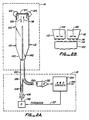
- Fig. 1 is a partially schematic and partially perspective view of an optical transducer for measuring a physical parameter to illustrate the preferred embodiment of this invention.
- the optical transducer 10 comprises an evaluation system 12 and a transducer system 14.
- the two systems are linked by optical fibers so that transducer 10 is particularly suitable for sensing physical parameters at remote locations.
- Transducer system 14 can be brought to such remote location to sense the physical parameter whereas the evaluation system 12 may be far away from such remote location.
- a light source 16 is controlled by a driver 18 to produce a constant light flux 20 into fiber optic light guide 22.
- the light source 16 may be, for instance, a light (including infrared) emitting diode (LED) and incandescent light bulb, an arc lamp, or a laser.
- the optical fiber 22 is optically joined to the base 44 of the piezoelectric quartz crystal tuning fork resonator 24 and provides a path for light 26 entering the quartz crystal from fiber 22.
- the light flux 26 is conducted by the quartz tuning fork crystal 24 which also acts as a light guide.
- This light guide phenomenon is a result of the highly polished mirror surfaces of the quartz crystal 24 and the difference in the indices of refraction between quartz and the surrounding medium. This operates in a manner similar to that experienced in step index optical fibers. Instead of mechanically or chemically polishing the surfaces of the quartz crystal, metallic coatings applied to the crystal surfaces may also provide a reflecting surface.
- the light flux 26 travels along both arms 28 and 30 of quartz crystal 24 as light fluxes 32 and 34 which are converged by the tape sections 36 and 38 of arms 28 and 30. These light fluxes then exit the quartz crystal at surfaces 40 and 42.
- the tuning fork crystal resonator 24 is constructed with a base 44 and a pair of tuning arms 28 and 30 which are separated by a gap 46.
- the pair of tuning arms 28 and 30 vibrate in opposite phase with respect to each other in the plane of the tuning fork in a mode known as the flexure mode at a fundamental vibration frequency in directions depicted by arrows 48 and 50.
- the X-cut tuning fork of Fig. 1 is fabricated using microlithographic techniques as described in U.S. Patent Nos. 3,683,213; 3,969,640; 3,969,641 and 4,377,765. This crystal is most typically used as a timing source for low powered, low cost applications such as in wrist watches.
- the resonator 24 may also be fabricated using any other piezoelectric materials such as rochelle salt (KNaC,H,06 . 4H 2 0), barium titanate (BaTiO a ), Tourmaline and ADP ((NH,)H 2 p O 4 ), or ferroelectric materials such as those referred to in the patents referenced above in this paragraph.
- Thin film driving electrodes 52 and 54 can be located along the top, bottom or sides of the arms 28 and 30 but preferably on the top surface as shown in Fig. 1. These electrodes can be manufactured by vacuum deposition of a conductive coating material such as tin oxide, nickel, chrome, gold, silver or a combination of these metal conductors. Upon application of an electrical potential across the two driving electrodes, arms 28 and 30 move in opposite phase and will continue to vibrate if driven in a manner well known in the art.
- a conductive coating material such as tin oxide, nickel, chrome, gold, silver or a combination of these metal conductors.
- Light fluxes 32 and 34 which are transmitted through surfaces 40 and 42 are projected on to the end of optical fiber 60.
- the magnitude of the light flux 62 in the optical fiber 60 depends on the flexural movements of arms 28 and 30.
- the continuous lateral movement of surfaces 40 and 42 causes a corresponding modulation of surfaces 40 and 42 causes a corresponding modulation of the light flux 62.
- the light flux 62 radiates from the distal end 64 of optical fiber 60 onto light detector 66.
- Photo detector 66 may be a pin photo diode, a photo-transistor, a photo-resistor or a photo-multiplier tube.
- the signal from photo detector 66 is amplified by amplifier 68.
- the amplitude of the AC component of the signal 70 from photo detector 66 is provided by the discriminator circuit 76 to provide an output signal 74 which represents the amplitude of the vibration of the arms 28 and 30 of resonator 24.
- a digital frqeuency signal 78 is also generated by discriminator circuit 76.
- Signal 78 is applied to a frequency counter 80 to provide an output signal representing the physical parameter which affects the vibration of arms 28 and 30 of resonator 24.
- Signal 78 is also applied thorugh a phase delay or phase-shifting element 84 and driver 86 to light source 88 which can be a LED or a solid state laser.
- Photo voltaic cell 92 may include a voltage regulator, a voltage doubler or other circuitry to assist in generating an oscillating driving signal.
- Cell 92 provides an output which is connected to the driving electrodes 52 and 54, thereby generating oscillations of the arms 28 and 30.
- the phase delay element 84 and the rest of the electrical circuit form a feedback control loop that causes the quartz resonator to remain in oscillation with the resonator 24 as the frequency controlling element.
- the crystal can alternatively be driven by periodic or random pulses of light from light source 88.
- the transducer system 14 is placed in such a manner that the frequency of vibration and/or the amplitude of vibration of resonator 24 is modulated by such physical parameter. Such modulations result in modulations of light flux 62 which is detected by photo-detector 66. Photo-detector 66 provides an electrical signal representing the light flux 62. The electrical components in evaluation circuit 12 then provides electrical signals 74 and 82 representing the amplitude, phase and frequency representing the amplitude, phase and frequency of the modulations caused by the physical parameter.
- the transducer system 14 forms a disposable part of the optical transducer 10.
- the quartz crystal tuning fork resonator 24 is of low cost as are the optical fiber leads within system 14 so that the entire system 14 can be disposed at will.
- the optical fiber leads of system 14 in the disposable arrangement may be connected to long optical fiber cables for connection to evaluation system 12 in a conventional manner.
- the resonance frequency of arms 28 and 30 of resonator 24 may be controlled.
- metal film weight 96 and 98 may be vacuumed deposited on resonating arms 28 and 30 during fabrication of the quartz resonator 24.
- portions of the weights 96 and 98 may be trimmed in a convenient manner such as by a laser. The appropriate amount of trimming may be performed to adjust the resonance frequency of resonator 24 to the desired frequency.
- differential trimming of the weights 96, 98 allows the matching of resonance frequencies of the two arms thereby optimizing the Q or quality factor of the crystal.
- Fig. 2A is a schematic view of an optical transducer illustrating an alternative embodiment of this invention.
- a single optical fiber or a bundle of fibers 100 conencts a quartz crystal tuning fork resonator 102 of a transducer system 14 and an evaluation system 12.
- light source 106 which can be an LED, laser or arc-lamp
- the light flux is modulated by the light absorbent gratings 114 and 116 as shown in Fig. 2B.
- Light flux 118 that makes its way through this double grating structure is conducted by the arms 110 and 112 acting as light guides to the photo-cell 120 located at the base of the quartz crystal resonator 102 as described in reference to Fig. 1.
- photo-cell 120 provides an output to driving electrodes (partially shown in Fig. 2A) of resonator 102 thorugh wires 122 and 124 to vibrate arms 110 and 112 in the fundamental flexure mode in a manner similar to that described in reference to Fig. 1.
- Part of the light flux 118 is reflected from the surface of photo cell 120. This is accomplished by either using the natural reflectivity of silicon of cell 120 or coating a partially reflecting mirror on the front surface of cell 120.
- a selective narrow band light absorbent coating can be located on the surface of the quartz crystal 102 to intercept the light flux 118. One preferred location of this coating is in front of the mirror coating of cell 120.
- the temperature of the quartz element 102 will be increased by the absorption of light energy by the gratings 114 and 116 and the absorption fo light energy within this narrow band by this selective absorbent coating.
- the temperature of the quartz element 102 can be controlled by varying the amount of the light energy within the narrow band. It will be undestood that the temperature of the crystal may be controlled in all the other embodiments of this invention in a manner similar to that just described.
- the reflected light 126 from cell 120 is only partially absorbed by its second passage through the double grating structure 114 and 116.
- the main part of light 126 passes back through the gap and the grating, is conducted back along optical fiber 100, through conventional fiber optic splitter 128 to impinge on photo detector 130.
- the signal from the photo detector is amplified by amplifier 132 and processed by analog and digital circuits of network 134 to provide an output signal 136 indicative of either the frequency, the amplitude, or phase of resonator 102.
- the vibrations of arms 110 and 112 of resonator 102 are influenced by a physical parameter to be measured and output 136 will indicate such modulation influence.
- the physical parameter is then detected and measured by means of the output signal 136.
- Network 134 also provides a signal 137 of the appropriate phase to light source driver 138 to control the light intensity of the light source 106 for resonating the resonator 102 in a conventional manner.
- the light source 106 normally provides a constant light flux 108. In some circumstances, however, it can be modulated or pulsed to initiate oscillation of the resonator 102.
- Arms 110 and 112 have tapered sections 140 and 142 whose taper are shallow enough for a given index ratio between quartz and the surrounding medium to allow for total internal reflection of the light fluxes 118 and 126.
- Gratings 114 and 116 are each formed by alternately arranged transparent and light absorbing strips.
- the grating 116 located on the ends of arms 110 and 112 move in opposite phase with respect to one another in directions of arrows 144 and 146.
- grating 116 may also be made of a light reflecting material such as mirrors which reflect part of light 108 back towards photo detector 130. In either configuration, the modulations of the vibrations of arms 110 and 112 caused by a physical parameter are detected by photo detector 130.
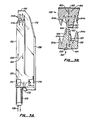
- Fig. 3A is a perspective view of a quartz crystal tuning fork resonator illustrating a second alternative embodiment of the invention.
- Fig. 3B is a partial cut away cross-sectional view of a portion of the resonator of Fig. 3A.
- an optical equivalent of the grating structure of Fig. 2 is manufactured at the same time when the resonator is photolithographically produced. This can reduce the number of steps and the cost required for its production.
- the evaluation system 12 of the alternative embodiment of Figs. 3A and 3B is the same as that of Figs. 2A and 2B and has been omitted for simplicity.
- the same referenced numerals for the optical fiber 100 and light flux 108 therein is used in Figs.
- a light flux 108 is transmitted through optical fiber 100 joined to the base of modified tuning fork resonator 150.
- Light flux 108 is conducted by vibrating arm 152.
- vibrating arm 152 ends in a plurality of tapered sections 154a which converge the light flux 108 and act as a modulating grating structure.
- Arm 158 has a U-shaped portion at its end with similar tapering end sections 154b opposite to sections 154a.
- the two groups of opposing tapering sections 154a and 154b form the optical equivalent of the grating structure of Figs. 2A and 2B.
- Fig. 3A shows the configuration for two opposing groups of three tapered sections in each group. It will be understood that 1, 2 or more than 3 tapered sections may be used in each group and are within the scope of this invention.
- Part of the light flux 108 is internally reflected by the sides 155 and converges light flux 108.
- Part of the light flux 108 is conducted into the upper part of arm 158 of resonator 130 as light flux 160.
- This transmitted light 160 is then reflected by mirror 162 as reflected light flux 164 which retraces its optical path back down light guide 152.
- Part of the light flux 108 reflects off the outside tapered surface 157 of arm 158 and is lost.
- the optically conductive end surfaces 168 and 170 of tapered sections 154a, 154b are constructed so that in the neutral non-vibrating position they are approximately 50% overlapping to provide the maximum optical modulation.
- Arm 158 is further tapered at 178 to reduce its mass so that arms 152 and 158 may have substantially the same resonance frequency as before. Thin film weights deposited on the two arms may be used to adjust their resonance frequencies to their desired value.
- the above described opposing groups of tapered sections increase the sensitivity of the optical sensor.
- the opposing surfaces of resonator 24 and optical fiber 60 may be shaped in a similar manner to increase the sensitivity of the optical sensor 10.
- the opposing surfaces may be provided with gratings similar to grating 114 and 116 of Fig. 2 to increase the sensitivity of the sensor.
- the opposing groups of tapered sections of Figs. 3A, 3B and/or the gratings of Fig. 2B may also be applied in a similar manner to other embodiments of this application, including but not limited to those of Figs. 5A, 7, 8A, 8B, 9A, 10, 11, 13A and 14A.
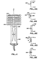
- Fig. 4 is a perspective view of a resonator illustrating a third alternative embodiment of this invention.
- the tuning fork resonator of Fig. 4 is particularly adapted for measurements with a resonator vibrating in the torsional mode as well as the flexure mode of the previous embodiments of Figs. 1-3.
- Measurements of physical parameters employing a tuning fork resonator vibrating in the torsional mode is advantageous in that the resonance frequency of the torsional mode vibration can vary substantially linearly with temperature of the resonator and is a single valued function.
- the resonance frequencies of resonators vibrating in the flexure mode has a frequency-temperature characteristic in the form of a parabola.
- a resonator such as that shown in Fig. 4 is advantageous for measuring temperature.
- the resonator of Fig. 4 may be vibrated in both the flexure and torsional modes.
- the two different vibrational modes can be electronically separated since they can differ substantially in frequency.
- the torsional mode can operate at 200 kHz with the flexure mode at 20 kHz.
- Resonator 180 comprises arms 186 and 188.
- Light 194 from a light source similar to that of source 16 of Fig. 1 is conducted through optical fiber 196 to arm 186.
- Fiber 196 is optically continuous with the base of resonator 180 such that light flux 194 is also conducted along arm 186 as light flux 198.
- Arms 186 and 188 taper in two different directions.
- One taper is on one side of arm 186 shown as 200.
- the other taper is on the bottom surface of arm 186 shown as surface 203.
- the first taper shown by surface 200 converges light flux 198 towards mirror 204.
- Light flux 198 is reflected off mirror 204 as light flux 206.
- the second taper as shown by surface 203 continues to converge light flux 206 towards surface 208. Part of this light crosses the small gap 210 and re-enters the resonator through surface 212 of arm 188.
- This light is then reflected by mirror 214 as light flux 216 down the arm 188 towards the base of resonator 180 as light flux 222.
- Flux 222 is then conducted by optical fiber 224 to the photo detector similar to detector 66 of Fig. 1.
- Arm 188 has corresponding tapering sections to those of arm 186 shown as surfaces 220 and 221.
- the two tapers result in very small rectangular areas 208 and 212 through which the two arms 186, 188 are optically coupled.
- the two arms 186, 188 vibrate in either the torsional mode (arrows 182-184), flexural mode (arrows 190,192) or the perpendicular (normal) mode (arrows 183, 185) or any combination of the three, the light coupling coefficient between the two arms of the resonator will be altered thereby modulating light flux 222 which is then detected by the photo detector.
- Light flux 226 which is generated by the optical and electrical feed back discussed above in reference to Fig. 1 is supplied through optical fiber onto photo cell 230.
- Cell 230 generates a varying electrical current for driving electrodes 232 and 234 to resonate the resonator 180.
- Locating fiber 228 and cell 230 between optical fibers 196 and 224 produces a compact configuration. Comparing Figs. 3A, 3B and 4 to Figs. 1, 2A and 2B, it will be obvious that the resonators of Figs. 3A, 3B and Fig. 4 together with the optical fiber leads attached thereto form the disposable portions of the optical transducer system and are disposable at will.
- the electrical pattern on resonator 180 can be configured to vibrate the arms in a torsional and/or flexure mode. These techniques are well known in the art and are described in U.S. Patent Nos. 4,377,765 and 4,382,204. If both modes are utilized in one measurement, light flux 226 contains both separate driving frequencies to independently drive the two modes. Thus, in the previous embodiments metal film weights may be deposited on resonator 180 for adjusting the resonance frequencies.
- a perpendicular flexure mode in which the arms move perpendicularly to the crystal plane as illustrated by arrows 183 and 185 can also be implemented with the appropriate locations of the driving electrodes.
- resonator 180 is vibrated in both the flexure and torsional modes simultaneously, two different physical parameters may affect each mode by different amounts. By calibrating the effects of each parameter on the two modes separately, it is possible, by measuring the frequencies of the modes, to measure the two parameters simultaneously. Two such parameters may be temperature and pressure.
- Fig. 5A is a simplified perspective view of a pair of opposing piezoelectric tuning forks with opposing grating patterns to illustrate the fourth alternative embodiment of this invention.
- Fig. 5 is a top view of the tuning forks of Fig. 5A.
- Light flux 250 is conducted by optical fiber 252 and collimated into a beam 254 by lens 256.
- Lens 256 may be a conventional condensing lens or a grated-index rod micro lens such as that manufactured by Nippon Sheet Glass Ltd.
- Light beam 254 can also be directly from a laser. Part of the collimated light beam 254 passes through the first quartz tuning fork 258 and the second quartz tuning fork 260 with their opposing grating elements 262, 264 as shown in Fig. 5B.
- Grating 262 is located on arms 266 and 268 while the opposing grating is located on arms 270 and 272. Light from the collimated beam that passes through this grating structure is projected onto photo cell 274 which produces an electrical current out of phase with the movement of the two tuning forks. Electrical connections 276 and 278 connect the output of the photo cell to drive tuning fork 260. The driving electrodes of tuning fork 260 are connected to the driving electrodes of tuning fork 258 in such a manner that the two tuning forks will vibrate in opposite phase. The connections are as shown in Fig. 5A. Thus, when arms 266 and 268 are moving apart flexurally arms 270 and 272 are moving towards each other thereby enabling the opposing grating structure to modulate the light beam 254.
- Optical fiber 252 also serves as the fiber to receive the light modulated by the grating structure for measuring the physical parameter.
- the first grating 262 is made of a light absorbing material or phosphor which can be used to indicate temperature.
- the second grating 264 is made of a light reflecting material.
- the light so detected is modulated by the combined actions of the two tuning forks. In this manner, the physical parameter modulating the vibrations of the two tuning forks can be detected and measured.
- the resonance frequencies of the two tuning forks may be adjusted by trimming metal film weights deposited thereon. If necessary, additional interconnection of electrodes between the two tuning forks can be made to help synchronize their movement.
- tuning forks 258, 260 are shown in the form of flat plates with thin thickness, it will be understood that their thicknesses are not limited to those shown but can be increased at will to be greater than their widths without affecting the functions of the tuning forks.
- the cross-sectional dimensions of the transducers in the other embodiments of this application can be similarly varied.
- the two tuning forks are preferably placed close together as shown in Fig. 5B.
- the two grating structures overlap by approximately 50% as shown in Fig. 5B so that each transparent strip of grating structure 262 overlaps on one side half of a corresponding opaque strip of grating structure 264.
- the opaque strips of grating structure 264 are similarly located with respect to grating 262. With such an arrangement maximum sensitivity to the relative movement between the two tuning forks is obtained.
- Fig. 6 is a schematic view of an optical pressure transducer to illustrate how the optical sensors of this invention can be used for measuring pressure.
- the pressure transducer 300 comprises a tubular enclosure 302 enclosed by an isolating diaphragm 304. Within the enclosure 302 is placed a quartz tuning fork type resonator 306 of the kind shown in Fig. 3A. While the resonator of Fig. 3A is shown in Fig. 6 for illustrating the pressure transducer it will be understood that any one of the tuning fork transducers described above can be used instead.
- the tuning fork resonators of the types described in reference to Figs. 7, 8A, 8B, 9A, 9B, 9C and 10 may also be used instead. All such configurations are within the scope of this invention.
- diaphragm 304 allows equilibrium between the internal pressure inside enclosure 302 and the external pressure outside of it.
- enclosure 302 is placed with its outlet leading to diaphragm 304 within such environment so that the internal pressure within the enclosure is equal to the pressure of the environment to be measured.
- the pressure inside enclosure 302 changes the gas density inside the enclosure and thus also the resonance frequency of resonator 306 and is transformed into an optical signal in the manner described above.
- Attached tubing 308 provides a uniform outside diameter to the pressure transducer while providing space for the optical fiber 310 and other instruments.
- the pressure transducer of Fig. 6 can be readily used as a catheter in medical applications.
- the pressure sensitivity of the transducer can be changed by placing different gases or gas mixtures with different density-pressure or viscosity-pressure characteristics surrounding the resonator.
- the pressure transducer of Fig. 6 can be used as a level detector by placing the transducer in a fluid near the bottom of a container and relating the pressure measured to the height of the fluid above the transducer if the density of the fluid is known or is measured.
- An additional pressure transducer of the same type placed in the container above the level of the fluid can measure and compensate for barometric pressure changes.
- To measure the density of the fluid two pressure transducers are placed in the fluid at a known vertical distance apart. The pressure differential between the two locations of the transducers will give the density of the fluid. This, combined with the pressure measured inside the fluid at the bottom of the container, will give the fluid level.
- Fig. 7 is a simplified perspective view of a micro-mass balance resonator to illsutrate how the optical sensor of this invention is used for detecting particles.
- the resonsator 350 is placed in an enclosure (not shown) and is connected to an evaluation system (also not shown) in a remote monitoring location via an optical fiber 352.
- This fiber can be configured into a rectangular end section 354 in order to more optimally interface with the resonator.
- the two vibrating tines 356 and 358 modulate the light reflected from a mirror 360 in a manner similar to those embodiments described above.
- An aperture plate 362 is positioned in front of the tuning fork and contains two open windows 364 and 366 which allow air born particles to pass into the enclosure and impinge upon and adhere to two areas 368 and 370 on the two tines.
- a coating of gold or nickel can be the adhesion surfaces 368 and 370.
- a sticky substance such as a thin layer of high temperature vacuum grease can adhere these particles. The additional mass of these particles increases the weight of the tines causing a corresponding decrease in the resonance frequency.
- the weight of particulate matter adhering to the crystal may be measured by measuring the corresponding change of the resonance frequency of the tuning fork 350.
- tuning fork 350 includes a frame 372. This facilitates the positioning of mirror/ photocell 360 with respect to the two tines 368 and 370 so that no extra parts will be necessary to hold the mirror in position with respect to the tines.
- the resonator of Fig. 1 may also include a frame so that optical fiber 60 can be attached to the frame to fix its position relative to the two tines 28 and 30.
- resonator 102 may also be integral with the frame so that optical fiber 100 can be attached to the frame.
- Fig. 8A is a schematic view of a quartz tuning fork resonator transducer for detecting and measuring gaseous pollutants.
- Vibrating tuning fork 400 can be of any of the types previously described. Both arms of the tuning fork 400 have chemically active compounds illustrated by 402 and 404 which bond to specific chemical compounds to be detected. The rest of the quartz crystal can be coated with a protective coating such as steatite or spinel which is not chemically active.
- the housing 406 contains a semi-permeable membrane 408 which selectively allows passage of the gas to be detected from the outside to the inside of the enclosure.
- the change in the mass of the tuning fork arms caused by the adherence of the gas molecules to areas 402, 404 causes a change in the resonance frequency of the tuning fork which can be remotely detected and measured.
- membrane 408 is hyperphobic and constructed from micro channel teflon which allows the passage of most gases except water vapor and if locations 402 and 404 are coated by a thin film of palladium
- transducer 400 can be used to detect the presence of most gases.
- More selective chemical sensors depends upon the nature of the membrane 408 and the bonding orsorptivity nature of the material on the tines.
- the membrane may be selectively chemically active to a particular chemical or antigen, resulting in the release of a gas subsequently sorbed by the areas 402 and 404.
- the transducer of Fig. 8A may also be used to detect pressure through the detection of condensation of a gas on the transducer. If the temperature of the gas surrounding the transducer is kept substantially constant, the condensation of the gas on the transducer is proportional to the pressure of the gas. By measuring the mass of condensation on the transducer, the pressure of the gas can be measured.
- Fig. 8B is a schematic view illustrating a further embodiment of a gaseous pollutant detector in which a double tuning fork arrangement is used.
- the enclosure 424 has gas permeable regions 426 and selective sorbent regions 428 and 430 which can be different materials and which therefore detect different gases.
- the input light beam 432 is modulated by the movement of both tuning forks to produce a modulated output signal 434 which contains the two resonance frequencies of the two tuning forks.
- An electrical processing unit (not shown) can separate these two different frequencies and thereby determine the changes in the frequencies and thus the amount of each of the two gases deposited on the two tuning forks.
- one of the tuning forks contains no chemically sorbent area but operates as a temperature or pressure sensor thereby forming a combined temperature-chemical sensor or pressure-chemical sensor. This capability is particularly useful where the detection of a chemical is highly dependent upon its temperature or pressure.
- tuning forks including tuning forks of the closed-end type (described below) may be employed to measure a number of gases or to monitor the temperature and pressure and to detect a chemical.
- tuning forks of shapes different from those shown in Fig. 8A may be used, such as tuning forks shown in Figs. 1, 2A, 3, 4, 5A, 9A and 10. All such arrangements are within the scope of this invention.
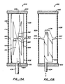
- Figs. 9A, 9B and 9C illustrate a fifth alternative embodiment of the invention, which includes a load-sensitive double bar resonator comprising two closed-end tuning fork resonators.
- the resonance characteristics of closed-end tuning fork resonators are well known in the art.
- the optical modulation techniques of the closed-end tuning fork resonators are similar to the open-end tuning fork resonators described above. In reference to Figs.
- the two closed-end tuning fork resonators 450 an 452 vibrate in substantially opposite phase so that light-absorbent grating 454 in combination with light-reflective grating 458 and light-absorbent grating 456 in combination with light-reflective grating 460 modulate the light reflected from gratings 458, 460 towards lens 464 which then focuses the reflected light toward optical fiber 462 for detection.
- the mirror/photocell 466 performs the same function as the element 274 of Figs. 5A and 5B.
- the pair of closed-end tuning fork resonators are placed symmetrically in an enclosure 468.
- the enclosure 468 is separated from the environment by a flexible diaphragm 470 which senses the pressure differential between the inside pressure P2 and the outside pressure P1 thereby causing a change in the force loading of the closed-end tuning fork resonators.
- a change in the force loading changes the resonance frequencies of the two resonators and the transducer of Figs. 9A, 9B and 9C can be used to measure the pressure differential.
- the transducers of Figs. 9A, 9B and 9C can also be used to measure a compression or tension force applied to the center of the diaphragm.
- a weight 472 placed at the center of the diaphragm will apply a force to the resonating structure and change their resonance frequencies as does any acceleration or vibration movement in the direction of the arrow 471.
- Fig. 10 is a partially cross-sectional and partially elevational view of an optical transducer to illustrate a sixth alternative embodiment of the invention and to also illustrate how the invention of this application may be used to measure force and pressure.
- a quartz crystal resonator 500 of the shape shown is used to measure the pressure or force P1.
- An optical fiber 502 sends and receives optical signals to resonator 500.
- Resonator 500 is enclosed by a housing 503 and a diaphragm 504 as in the previous pressure transducer embodiments.
- a pressure or force P1 acts on the diaphragm 504 to change the resonance frequencies of the two bar resonators 506 and 508.
- the two bar resonators are preferably loaded by the same load so that they have the same resonance frequencies to simplify the detection and measurement of the modulations of their resonance frequencies. To insure that the two resonators are loaded by the same load P1 should be applied to the diaphragm 504 in a symmetrical manner.
- Bar resonators 506 and 508 are each equipped with protruding portions forming shutters 522, 524.
- the transducer shown in Fig. 10 forms the disposable part of a measuring instrument connected to optical fiber 502 where the instrument may be located remote from the location of measurement.
- the amount of pressure actually transmitted by the diaphragm to resonator 500 depends on the stiffness of the diaphragm. If the diaphragm is stiff, much of the pressure may be born by the frame of the enclosure 503 and only a smaller portion by the resonator. By selecting a diaphragm of the appropriate stiffness, the transducer 500 can be tuned to detect pressure in a desired range.
- the optical sensors of Figs. 9A, 9B and 9C and of Fig. 10 are two embodiments employing closed-end tuning fork type transducers. As described above both embodiments may be used for measuring pressure or force. The two embodiments, however, can also be used for measuring a number of other physical parameters if a mass 472 of Fig. 9B is placed on top of the transducer in either embodiment. Both can be used to measure acceleration. If the mass put on top of the transducer is at zero acceleration, the modulation of the resonance frequency simply indicates the weight of the mass. If the transducer is accelerated, however, the acceleration of the transducer will cause the mass to exert a force on the transducer that is greater or less than its own weight depending on the direction of acceleration.
- Elements 510, 512 can be made to vibrate by driving electrodes (not shown) in a conventional manner.
- Either one of the two elements may be made into an open-end tuning fork with a gap therein.
- element 510 is shown to have a gap 563 (shown in phantom) so that element 510 becomes an open-end tuning fork with two symmetrical tines separated by gap 563.
- the open-end tuning fork formed by either element can be made to vibrate at a distinguishable frequency from the vibrations of the closed-end tuning fork. If such open-end tuning fork is used to measure temperature, the entire apparatus of Fig. 10 may be used to measure simultaneously temperature and another physical parameter such as pressure, force or acceleration.
- the two embodiments of the closed-end tuning fork can also be used for measuring vibration or acoustic waves.
- Diaphragm 470 or diaphragm 504 are vibrated by the acoustic wave causing a varying pressure or force to be applied to the transducer of the two embodiments. Such varying force or pressure is sensed in the same manner as that described above in reference to Figs. 9A, 9B, 9C and -10.
- the two embodiments of the closed end tuning forks may be used in a manner similar to that for the open-end tuning fork described in reference to Figs. 4, 7, 8A and 8B for detecting temperature, chemicals and particulates. All such applications are within the scope of this invention.
- FIG. 11 is a simplified cross-sectional view of a closed-end tuning fork resonator for detecting displacements.
- Closed-end tuning fork 540 is either connected to or integral with a compliant multiple leaf spring element 542.
- the spring element particularly when configured from a single piece of quartz, acts as a low hysteresis, highly linear and compliant spring element.
- a displacement dX bends the quartz beams 544 having a spring constant K. This results in a tension or compression force on the tuning fork resonator 540.
- spring 542 translates displacement dX into a force on the resonator 540 which is then measured in a manner described above.
- the magnitude of the force on resonator 540 may be adjusted by selecting the desired spring constant K for spring 542.
- the spring with an appropriate spring constant for translating a displacement dX into a desired force may be selected in a conventional manner.
- the mirror/photocell 546 performs the same function as element 518 of Fig. 10.
- Figs. 12A through 12E are schematic views illustrating how the optical sensors of this invention may be used for measuring still other physical parameters. Such applications are alike in that the physical parameter is first converted into a representative electrical signal which is then applied to a piezoelectric or ferroelectric crystal to vibrate the crystal. The vibrations of the crystal are then optically detected to measure the physical parameter. All the open and closed-end tuning fork type transducers described above may be used for measuring physical parameters in such manner. Since the driving energy for vibrating the crystal transducer originates from the physical parameter or variable to be measured itself, the photo cell which has been used in previous embodiments is no longer needed for vibrating the crystal.
- Fig. 12A is a schematic view of a portion of a transducer system for measuring a light signal.
- the light signal 550 is directed towards a photo detector 552 which generates a voltage representative of the light signal 550.
- the voltage signal across terminals A, B is then applied to the driving electrodes of the open and closed end tuning fork transducers of the above-described embodiments for measuring the AC component of the light signal.
- Fig. 12B is a schematic view of a portion of a transducer arrangement for measuring electromagnetic or radiation signals.
- the electromagnetic or radiation signal 554 is directed toward a conversion screen 556 which converts the signal into a light signal by means of luminescence that is detected by photodetector 558 which, in turn, generates a voltage signal across terminals A, B.
- the voltage signal is then again applied to the driving electrodes of the open and closed-end tuning fork transducers of the above described embodiments for measuring the signal.
- a number of phosphor and crystal based converter screens are available for converting either UV, visible, IR light, radiation or ionizing or X-ray radiation signals into light signals.
- the phosphor converter screen of the type manufactured by 3M Company under the tradename Trimax O can be used for detecting X-rays.
- Many other known fluorescent materials may be used. The proper material may be selected depending on the particular signal to be measured.
- Fig. 12C is a schematic view of a portion of a transducer system for measuring an electrical signal.
- the varying electrical signal 560 may be applied directly to drive the open and closed-end tuning fork type transducers described above.
- a DC blocking capacitor 562 may be used to block the DC component of the signal 560 if the DC component is too great for quartz crystals.
- Capacitor 562 may also be used as a transducer if the amplitude of electrical signal 560 is maintained constant.
- the capacitance of the capacitor may be changed by mechanically tuning the capacitor or by the influence of a varying physical parameter such as temperature, pressure or acoustic waves. This then causes a changing voltage potential on terminals A and B which can be detected optically using the optical sensors of this application.
- Fig. 12D is a schematic view of a portion of a transducer system for measuring a varying magnetic field.
- a magnetic transducer such as a coil of wire 564 is placed in the presence of the changing magnetic field 566.
- the changing magnetic field generates a voltage signal across the terminals A, B which is used to drive the tuning fork transducers for detecting the magnetic signal 566.
- Fig. 12E is a schematic view of a portion of a transducer system for measuring a force.
- Force 568 is applied to a piezoelectric force transducer 570 causing the transducer to produce a voltage signal across terminals A and B which is used to drive the tuning fork type transducers described above in reference to Figs. 1-11 to measure such force.
- the transducers are vibrated by the light from a light source and a feedback system.
- the physical parameter to be measured modulates the vibrations of the transducers.
- the physical parameter is then measured by measuring such modulations.
- the physical parameter may be measured by measuring the amplitude, frequency or phase of the modulations of the tuning fork vibrations.
- the physical parameter to be measured is first converted into an electrical signal which is then used to move the tuning fork transducers. No separate light source or photo cell is used to vibrate the transducers.
- the tuning fork does not modulate at or below its resonance frequency. Instead the tines or bars of the tuning fork move apart or closer to each other in response to the electrical voltage. Such displacement is measured for measuring the physical parameter.
- Described below are still other embodiments employing quartz crystals where the crystals are not separately vibrated by a light source and the photo cell as in the embodiments described in reference to Figs. 1 through 11. Instead, the crystals respond to the physical parameter to be measured directly. It will be understood that, while the embodiments below are described as quartz crystal transducers, other transducers made of other materials may be used as long as such transducers can bend or flex under the influence of physical parameters. All such configurations are within the scope of this invention.
- transducer 600 comprises a quartz crystal essentially having the same shape as crystal 500 of Fig. 10.
- the two fingers 622 and 624 are each in contact with a respective diaphragm 626 and 628.
- the two diaphragms are mounted on frame members 630 and 632 attached to the crystal 602.
- Optical fiber 634 passes through a hole in member 632 for transmitting the modulated light signal from crystal 602.
- Light is supplied to crystal 602 through fiber 634 from a light source (not shown).
- the light supplied passes through arms 614, 612 is reflected by mirror 636 and retraces its path to fiber 634 which transmits the reflected light to a photo detector (not shown).
- the physical parameter to be measured such as force, pressure, displacement and acoustic waves may be applied to the two diaphragms 626 and 628.
- transducer 600 can also be used as an accelerometer.
- Fig. 13B is a cross-sectional view of yet another quartz tuning fork type transducer illustrating an eighth alternative embodiment of this invention.
- transducer 650 comprises a tuning fork crystal 652 which is essentially the same as crystal 150 of Fig. 3A except for the fact that crystal 652 is slightly different in shape compared to crystal 150 and that crystal has two extra fingers 622, 624.
- transducer 650 of Fig. 13B is identical to transducer 600 of Fig. 13A except that a different shaped crystal 652 is used instead of crystal 602 of Fig. 13A.
- the parts that are identical functionally in the two figures are denoted by the same numerals.
- transducer 650 of Fig. 13B may be used to measure pressure, force, displacement, acceleration and acoustic waves.
- Transducer embodiments of Figs. 1, 2A, 4, 5A may be similarly modified and used instead o' crystal 652 in Fig. 13B. All such configurations are within the scope of this invention.
- Fig. 14A is a perspective view of an optical transducer illustrating the ninth alternative embodiment of this invention.
- the optical transducer 700 comprises a quartz crystal 702 having a central tine 704 surrounded by a frame 706. Tapering of the crystal at one end causes the central tine and the surrounding frame to become very thin at their apex. Such tapering can also be seen from the partial cross-sectional view of crystal 702 in Fig. 14B.
- Optical fiber 710 supplies light to crystal 702 which is reflected from mirror 712 to be received back by fiber 710.
- a thick metal film weight 714 plated on the end of the central tine increases the moment of inertia of the central tine relative to the surrounding tine for detecting acceleration. Movements in the direction depicted by 716 causes relative displacement between the central tine and its frame thereby also causing optical modulation of the light beam reflected back towards fiber 710.
- the central tine can also be connected through an elongated member such as rod 718 to a suitably mounted diaphragm 720.
- the physical parameter to be measured such as pressure, force, displacement or acoustic waves cause diaphragm 720 to move. Motion of the diaphragm is transmitted by rod 718 causing relative motion between the central tine and its frame thereby also modulating the light transmitted back towards fiber 710. The physical parameter can then be measured. Again by putting a mass in contact with diaphragm 720, acceleration of the mass can be measured in the same manner.
- Fig. 15 is a simplified schematic view of a transducer system where the transducer element is partially cut away and shown in perspective to illustrate the tenth alternative embodiment of this invention.
- the transducer system 800 comprises a sensing unit 802.
- Unit 802 includes a housing 804 with two windows 806 and 808.
- Housing 804 contains a tuning fork sensor 810.
- Tuning fork 810 may either be the open or closed-end type operating in the flexure, torsional or perpendicular vibrating modes.
- the sensing unit 802 may be used to sense any of the physical parameters discussed above in reference to other embodiments.
- the inside surface 812 of housing 804 can be either light absorbing or light reflecting depending upon the particular vibration or mode of the tuning fork.
- the source 820 directs the laser 822 towards tuning fork 810.
- Laser beam 822 is either reflected or modulated by the tuning fork and the reflected or modulated light 824 is eventually received by a detecing system 830 for measuring the physical parameter modulating the vibrations of the tuning fork 810.
- the manner in which light beam 822 is modulated by the vibrations of tuning fork 810 resulting in the modulated light beam 824 is described below in reference to Figs. 16A, 16B and 16C.
- Part of the laser beam 822 also enters window 808 and impinges on photo cell 832.
- Cell 832 provides electrical energy to drive an integrated oscillator 834 which in turn electrically drives tuning fork 810.
- transducer system of Fig. 15 The advantage of the transducer system of Fig. 15 is that a number of transducer elements may be placed at scattered and otherwise unaccessible locations, where such elements are interrogated by laser beams. No optical fibers or connections other than laser beams are necessary so that the system can be made and operated at low cost.
- Figs. 16A, 16B and 16C are schematic views of the tines 842, 844 of tuning fork 810 illustrating the different ways in which the vibration of the tuning fork modulates the light beam 822.
- tuning fork 810 may vibrate in a torsional mode.
- the front surface of the two tines are coated with a light reflective material so that light beam 822 will be reflected into beams 824 at an angle to beam 822.
- inside surface 812 of Fig. 15 is light absorbent.
- Detection system 830 detects the frequency or amount of rotation of the tines for measuring the physical parameter which modulates the vibrations of the tuning fork.
- Fig. 16B the two tines vibrate in the flexural mode.
- the front surface of the two tines are coated with a light absorbent material.
- a mirror or retro-reflecting element 846 is placed behind the tines.
- Light beam 822 is then reflected by mirror 846 along its incoming path.
- the flexural vibrations of the tines modulates the amount of light reflected by mirror 846.
- the physical parameter to be measured modulates the vibrations of the tines. Therefore, measurement of the modulations of beam 824 indicates the phase, frequency or amplitude of the physical parameter.
- the front surface of the two tines are coated with a light reflective material.
- the two tines are placed between a light absorbent screen 850 with an aperture therein so that when the tines vibrate the reflective area of the tines covered by screen 850 is modulated. In such manner vibrations of the tines modulates the intensity of the reflected beam 824.
Abstract
Description
- This invention relates in general to transducers and in particular to optical sensors for detecting and measuring physical parameters by converting such parameters into modulated light signals.
- Optical sensors have been developed to replace traditional electrical sensors to measure physical variables not possible with electrical sensors and to provide better performance. Other reasons for preferring optical over electrical signal sensing and transmission is the elimination of electromagnetic interference and inherent electrical isolation.
- One type of conventional optical sensors employs fiberoptic techniques. In U.S. Patent No. 4,071,753 to Fulenwider et al., the ends of an input and an output optical fiber are aligned and light is transmitted from one fiber to the other. Various means (apparently mechanical means) couple the end of the output optical fiber to a mechanical or acoustic source. The mechanical or acoustic signal from the source varies the optical coupling coefficient between the two fibers so that by measuring such coefficient, the mechanical or acoustic information can be measured. Fuller in U.S. Patent No. 4,419,895 discloses an angular accelerometer comprising a pair of cantilevered optical fibers which are parallel but somewhat misaligned. Angular movement modulates the optical signals coupled between the two optical fibers. By measuring such modulations, the angular accelerations are detected. In the above-described type of transducers, the optical sensor comprises two optical fibers optically coupled. The optical coupling coefficient between the two fibers varies with the physical parameter to be measured, so that by measuring such coefficient, the parameter can be detected and measured.
- In another type of optical sensors the physical parameter to be measured modulates the vibratory motion of a transducer element. Such modulation changes the intensity of light coupled between the ends of two optical fibers so that by measuring such changes the physical parameter can be detected and measured. Such type of transducers is disclosed in U.S. Patent No. 4,345,482 to Adolfsson et al. The transducer element may be a vibrating spring, a ferroelectric or a piezoelectric element. In U.S. Patent No. 4,379,226, Sichling et al. disclose a somewhat analogous optical sensor. The transducer element used in Sichling et al. is a leaf spring torsional rotational device, a ferromagnetic element attached to a filament or a piezoelectric element such as a quartz crystal. Sichling et al. also disclose an arrangement in which a mirror is attached to a transducer element which reflects light received from the input optical fiber towards the output optical fiber to accomplish the light coupling between the two fibers.
- Piezoelectric quartz resonators have been disclosed in more detail in other patents such as U.S. Patent No. 3,561,832 to Karrer et la. Such resonators exhibit changes in frequency when subjected to stress and may be used to measure stress. A ferromagnetic turning fork is used for measuring gas pressure as disclosed in U.S. Patent No. 3,902,355 to Weisser. The resonance frequency of the tuning fork is altered by changes in the gas pressure so that by measuring the modulations in resonance frequency of the tuning fork the gas pressure can be measured. In U.S. Patent No. 4,279,028, Lowdenslager et al. disclose the use of an unsealed tuning fork quartz crystal for measuring atmospheric pressure change using the same principle. In an article entitled "Using the X-Y Flexure Watch Crystal as a Pressure-Force Transducer", Proceedings of 31st Annual Frequency Control Symposium 1977, U.S. Army Elect Command, A. Genis et al. disclose the use of an X-Y flexure watch crystal for measuring pressure by the same principle. None of the above disclosures on the quartz crystal, however, appear to teach the use of the optical properties of the quartz crystal simultaneously with its piezoelectric properties.
- An optical sensor utilizing a grating structure connected to a diaphragm in a hydrophone is disclosed by W. B. Spillman in the article entitled "Multimode Fiber-Optic Hydrophone Based on a Schlieren Technique", Vol. 20 No. 3 of Applied Optics, February 1981. The grating structure is placed between the ends of two optical fibers to vary the light coupled between the two fibers. Thus an acoustic signal which causes the diaphragm to vibrate will cause a corresponding variation in the light coupled between the two fibers. The acoustic signal is then measured by the modulation in the light coupling between the fibers. Various hydrophones for measuring acoustic waves are disclosed in the above-referenced article by W. B. Spillman.
- Piezoelectric sensors have been used to detect machinery vibrations such as engine knock in an internal combustion engine. Such an application is described in U.S. Patent No. 4,349,404 to Hamisch et al. The high impedance associated with this type of piezoelectric acceleration sensors are prone to electrical noise such as that generated by engine ignition systems. An accelerometer employing a brass cantilevered beam is described by Sorf et al in the paper "Tilting-mirror Fiber-optic Accelerometer", Applied Optics, Vol. 23, No. 3, February 1, 1984.
- In addition to the detection and measurement of force, pressure, stress and acoustic waves, quartz crystal vibrators have been used to measure temperature. One such instrument, Model HP 2801 manufactured by Hewlett-Packard, Palo Alto, California, is based upon a crystal thermometer described by Hammond in U.S. Patent No. 3,423,609. Statek of Orange, California, manufactures a quartz thermometer tuning fork (Model TS-2). In U.S. Patent No. 4,398,115 Gagnepain et al. also describes the temperature indicating quartz crystal plate.
- Quartz crystal detectors have also been used as highly sensitive micro-balance detectors. Quartz crystals coated with a tacky substance or a substance which selectively absorbs and/or adsorbs a particular chemical or molecule increases the mass of the oscillator causing a decrease in its resonance frequency. Dorman in U.S. Patent No. 3,561,253 describes a particle detector system using an oscillating quartz crystal plate. Chuan in U.S. Patent No. 3,715,911 measures the mass of atmospheric particulate matter with a vibrating quartz crystal plate micro balance. Crystals coated with a selectively absorbent coating is described in U.S. Patent Nos. 4,111,036 to Frechette et al. (for detecting sulfur dioxide), 4,193,010 to Kompanek and in an article entitled "Analysis of Environmental Pollutants Using a Piezoelectric Crystal Detector", in Intern. J. of Environ. Anal. Chem., 1981 Vol. 10, pp. 89-98 by Guilbault.
- In all the above-described applications for measuring a physical parameter using the quartz crystal, the crystal is used as a non-optical vibrating detector which provides electrical signals for the detection and measurement of the physical parameters. These electrical signals are then processed by electronic circuitry. Such quartz crystal detectors are subject to electromagnetic interference which is undesirable.
- Techniques for fabricating quartz crystal resonating structures such as microlithographical, chemical and other manufacturing processes are well known to those skilled in the art. Such processes are disclosed for example in U.S. Patent Nos. 3,683,213 and 3,969,640 both issued to Staudte. Also well known in the art are the techniques for defining the cut of quartz crystal resonators to provide certain temperature- frequency characteristics, to tune their resonance frequencies, and to define the location and configuration and excitation electrodes to cause movements such as the flexure and twisting (torsional) modes of tuning forks. These movements can be at the fundamental and/or overtone frequencies of the crystal. Examples of these techniques are disclosed in U.S. Patent Nos. 3,969,641 by Oguchi et al; 4,377,765 by Koqure et al; 4,382,204 by Yoda and 4,384,232 by Debely. In addition, quartz crystal tuning forks may be vibrated in directions normal to the plane containing both tines of the tuning fork. Such techniques are also well known.
- In EP-A-0005798 various sensors are described in which light is modulated in accordance with a physical parameter to be detected, including that of Fig. 6, which shows an accelerometer in which a light transmissive quartz plate carrying a grating is used to modulate light.
- In another prior art device, shown in "Patent Abstracts of Japan, Vol. 7, No. 93, p. 192, 19 April 1983" a pair of comb-shaped electro-acoustic transducers is used to generate an acoustic surface wave in a waveguide. In this device, single mode light is supplied to the incident prism, and then propagates in the waveguide toward emission prism. If the mode of the light introduced into the optical waveguide is set at TE1, partial conversion to a different mode, TE3, takes place over a certain range of frequencies. Upon emerging from a prism, the quantity of light in each of the two modes TE1 and TE3 can be detected. The mode conversion is particularly efficient when the frequency of the elastic wave in the waveguide is at a particular value. By altering this frequency, one can alter the efficiency of mode conversion. When pressure is applied to the device, this will alter the frequency of the elastic wave. As mentioned, this alteration in frequency, alters the efficiency of mode conversion, and thus one can obtain an indication of the quantum of pressure by determining the amount of light which has undergone mode conversion.
- According to the instant invention, there is provided a transducer apparatus for detecting a physical parameter including a piezoelectric member for altering light, a means for stimulating the piezoelectric member to alter the light, a means for supplying light to be altered by said piezoelectric member, and a means for detecting alteration in the light to detect said physical parameter, characterized in that the alterations in the light are light intensity modulations, and in that said means for stimulating is a means arranged to cause the member to resonate piezoelectrically, such that the said physical parameter changes the resonant frequency of the piezoelectric member, and in that the apparatus further comprises means responsive to the intensity modulations of the light and arranged to determine changes in the resonant frqeuency of the member to detect said physical parameter.
- This will be discussed in more detail hereinafter in connection with the drawings.
-
- Fig. 1 is a partially schematic and partially perspective view of an optical transducer for measuring a physical parameter to illustrate the preferred embodiment of this invention.
- Fig. 2A is a schematic view of an optical transducer illustrating an alternative embodiment of this invention.
- Fig. 2B is an elevational view of a portion of the transducer of Fig. 2A illustrating the light absorbent gratings of the alternative embodiment.
- Fig. 3A is a perspective view of a quartz crystal tuning fork resonator illustrating a second alternative embodiment of the invention.
- Fig. 3B is a partial cut-away cross-sectional view of a portion of the resonator of Fig. 3A.
- Fig. 4 is a perspective view of a resonator illustrating a third alternative embodiment of this invention.
- Fig. 5A is a simplified perspective view of a pair of opposing piezoelectric tuning forks with opposing grating patterns to illustrate the fourth alternative embodiment of this invention.
- Fig. 5B is a top elevational view of the pair of tuning forks of Fig. 5A.
- Fig. 6 is a schematic view of an optical pressure transducer to illustrate how the optical sensors of this invention can be used for measuring pressure.
- Fig. 7 is a simplified perspective view of a micro-mass balance resonator to illustrate how the optical sensor of this invention is used for detecting particles.
- Fig. 8A is a schematic view of a quartz tuning fork resonator transducer for detecting and measuring gaseous pollutants.
- Fig. 8A is a schematic view illustrating a further embodiment of a gaseous pollutant detector in which a double tuning fork arrangement is used.
- Figs. 9A, 9B and 9C illustrate a load-sensitive double bar resonator comprising two closed-end tuning fork resonators to illustrate the fifth alternative embodiment of this invention.
- Fig. 10 is a cross-sectional view of an optical transducer to illustrate a sixth alternative embodiment of the invention, and to also illustrate how the invention of this application may be used to measure force and pressure.
- Fig. 11 is a simplified cross-sectional view of a closed-end tuning fork resonator for detecting displacements.
- Figs. 12A through 12E are schematic diagrams illustrating how the optical sensors of this invention may be used for measuring still other physical parameters including light, electrons, X-ray, radiation, electrical signal, magnetic signal and force.
- Fig. 13A is a cross-sectional view of a transducer to illustrate a seventh alternative embodiment of this invention.
- Fig. 13B is a cross-sectional view of yet another quartz tuning fork type transducer illustrating an eighth alternative embodiment of this invention.
- Fig. 14A is a perspective view of an optical transducer illustrating the ninth alternative embodiment of this invention.
- Fig. 14B is a partial view of the upper section of the transducer of Fig. 14A, illustrating the movement of the central tine.
- Fig. 15 is a simplified schematic view of a transducer system where the transducer element is partially cut away and shown in perspective to illustrate the tenth alternative embodiment of this invention.
- Figs. 16A, 16B and 16C are schematic views of the transducer element of Fig. 15 illustrating the different ways in which the vibration of the transducer element modulates a light beam.
- This invention provides for a miniature size transducer of high sensitivity which provides optical signals immune to electromagnetic interference and noise. In some embodiments of this invention, physical parameters are measured by detecting the frequencies of vibrations of the transducer; such frequencies are not degraded by transmission losses. The quartz crystal transducers of this invention are readily fabricatable since the manufacturing processes of quartz crystals and quartz crystal tuning forks have been developed to the extent that such transducers can be produced with high precision and at low cost. In contrast to conventional transducers, the quartz crystal transducers of this invention are used not only for their piezoelectric properties but also for their optical properties. Fiber optic techniques are used in many of the embodiments of this invention to achieve electrical isolation and immunity to electromagnetic interference and noise.
- Fig. 1 is a partially schematic and partially perspective view of an optical transducer for measuring a physical parameter to illustrate the preferred embodiment of this invention. As shown in Fig. 1 the
optical transducer 10 comprises anevaluation system 12 and atransducer system 14. The two systems are linked by optical fibers so thattransducer 10 is particularly suitable for sensing physical parameters at remote locations.Transducer system 14 can be brought to such remote location to sense the physical parameter whereas theevaluation system 12 may be far away from such remote location. - To provide light to the
transducer system 14 for measuring the physical parameter, alight source 16 is controlled by adriver 18 to produce aconstant light flux 20 into fiber opticlight guide 22. Thelight source 16 may be, for instance, a light (including infrared) emitting diode (LED) and incandescent light bulb, an arc lamp, or a laser. Theoptical fiber 22 is optically joined to thebase 44 of the piezoelectric quartz crystaltuning fork resonator 24 and provides a path for light 26 entering the quartz crystal fromfiber 22. Thelight flux 26 is conducted by the quartztuning fork crystal 24 which also acts as a light guide. This light guide phenomenon is a result of the highly polished mirror surfaces of thequartz crystal 24 and the difference in the indices of refraction between quartz and the surrounding medium. This operates in a manner similar to that experienced in step index optical fibers. Instead of mechanically or chemically polishing the surfaces of the quartz crystal, metallic coatings applied to the crystal surfaces may also provide a reflecting surface. Thelight flux 26 travels along botharms 28 and 30 ofquartz crystal 24 as light fluxes 32 and 34 which are converged by thetape sections 36 and 38 ofarms 28 and 30. These light fluxes then exit the quartz crystal at surfaces 40 and 42. - The tuning
fork crystal resonator 24 is constructed with abase 44 and a pair of tuningarms 28 and 30 which are separated by a gap 46. The pair of tuningarms 28 and 30 vibrate in opposite phase with respect to each other in the plane of the tuning fork in a mode known as the flexure mode at a fundamental vibration frequency in directions depicted byarrows 48 and 50. - The X-cut tuning fork of Fig. 1 is fabricated using microlithographic techniques as described in U.S. Patent Nos. 3,683,213; 3,969,640; 3,969,641 and 4,377,765. This crystal is most typically used as a timing source for low powered, low cost applications such as in wrist watches. Instead of quartz, the
resonator 24 may also be fabricated using any other piezoelectric materials such as rochelle salt (KNaC,H,06 . 4H20), barium titanate (BaTiOa), Tourmaline and ADP ((NH,)H2 pO4), or ferroelectric materials such as those referred to in the patents referenced above in this paragraph. - Thin film driving electrodes 52 and 54 can be located along the top, bottom or sides of the
arms 28 and 30 but preferably on the top surface as shown in Fig. 1. These electrodes can be manufactured by vacuum deposition of a conductive coating material such as tin oxide, nickel, chrome, gold, silver or a combination of these metal conductors. Upon application of an electrical potential across the two driving electrodes,arms 28 and 30 move in opposite phase and will continue to vibrate if driven in a manner well known in the art. - Light fluxes 32 and 34 which are transmitted through surfaces 40 and 42 are projected on to the end of optical fiber 60. The magnitude of the
light flux 62 in the optical fiber 60 depends on the flexural movements ofarms 28 and 30. The continuous lateral movement of surfaces 40 and 42 causes a corresponding modulation of surfaces 40 and 42 causes a corresponding modulation of thelight flux 62. Thelight flux 62 radiates from thedistal end 64 of optical fiber 60 ontolight detector 66.Photo detector 66 may be a pin photo diode, a photo-transistor, a photo-resistor or a photo-multiplier tube. The signal fromphoto detector 66 is amplified byamplifier 68. The amplitude of the AC component of thesignal 70 fromphoto detector 66 is provided by thediscriminator circuit 76 to provide anoutput signal 74 which represents the amplitude of the vibration of thearms 28 and 30 ofresonator 24. Adigital frqeuency signal 78 is also generated bydiscriminator circuit 76.Signal 78 is applied to afrequency counter 80 to provide an output signal representing the physical parameter which affects the vibration ofarms 28 and 30 ofresonator 24.Signal 78 is also applied thorugh a phase delay or phase-shiftingelement 84 anddriver 86 tolight source 88 which can be a LED or a solid state laser. - Light from
source 88 is conducted via thelight guide 90 to the photo diode or photovoltaic cell 92. In some circumstances, photovoltaic cell 92 may include a voltage regulator, a voltage doubler or other circuitry to assist in generating an oscillating driving signal.Cell 92 provides an output which is connected to the driving electrodes 52 and 54, thereby generating oscillations of thearms 28 and 30. Thephase delay element 84 and the rest of the electrical circuit form a feedback control loop that causes the quartz resonator to remain in oscillation with theresonator 24 as the frequency controlling element. Instead of employing a feedback loop, the crystal can alternatively be driven by periodic or random pulses of light fromlight source 88. - To measure a physical parameter the
transducer system 14 is placed in such a manner that the frequency of vibration and/or the amplitude of vibration ofresonator 24 is modulated by such physical parameter. Such modulations result in modulations oflight flux 62 which is detected by photo-detector 66. Photo-detector 66 provides an electrical signal representing thelight flux 62. The electrical components inevaluation circuit 12 then provideselectrical signals - No additional electrical circuitry is used in the
transducer system 14 or the connections betweentransducer system 14 and theevaluation system 12.Evaluation system 12 can be placed away from the location of measurement and in an electrically isolated environment. In this manner, thetransducer system 10 of Fig. 1 is immune from electromagnetic noise interference. Thetransducer system 14 forms a disposable part of theoptical transducer 10. The quartz crystaltuning fork resonator 24 is of low cost as are the optical fiber leads withinsystem 14 so that theentire system 14 can be disposed at will. The optical fiber leads ofsystem 14 in the disposable arrangement may be connected to long optical fiber cables for connection toevaluation system 12 in a conventional manner. - The resonance frequency of
arms 28 and 30 ofresonator 24 may be controlled. For example,metal film weight 96 and 98 may be vacuumed deposited on resonatingarms 28 and 30 during fabrication of thequartz resonator 24. To increase the resonance frequency of the resonator, portions of theweights 96 and 98 may be trimmed in a convenient manner such as by a laser. The appropriate amount of trimming may be performed to adjust the resonance frequency ofresonator 24 to the desired frequency. In addition, differential trimming of theweights 96, 98 allows the matching of resonance frequencies of the two arms thereby optimizing the Q or quality factor of the crystal. - Fig. 2A is a schematic view of an optical transducer illustrating an alternative embodiment of this invention. In this embodiment a single optical fiber or a bundle of
fibers 100 conencts a quartz crystaltuning fork resonator 102 of atransducer system 14 and anevaluation system 12. Turning first to theevaluation system 12, light source 106 (which can be an LED, laser or arc-lamp) supplies alight flux 108 tofiber 100 to the vibrating ends ofarms resonator 102. The light flux is modulated by the lightabsorbent gratings Light flux 118 that makes its way through this double grating structure is conducted by thearms cell 120 located at the base of thequartz crystal resonator 102 as described in reference to Fig. 1. In response tolight flux 118, photo-cell 120 provides an output to driving electrodes (partially shown in Fig. 2A) ofresonator 102thorugh wires arms - Part of the
light flux 118, however, is reflected from the surface ofphoto cell 120. This is accomplished by either using the natural reflectivity of silicon ofcell 120 or coating a partially reflecting mirror on the front surface ofcell 120. In addition, a selective narrow band light absorbent coating can be located on the surface of thequartz crystal 102 to intercept thelight flux 118. One preferred location of this coating is in front of the mirror coating ofcell 120. The temperature of thequartz element 102 will be increased by the absorption of light energy by thegratings quartz element 102 can be controlled by varying the amount of the light energy within the narrow band. It will be undestood that the temperature of the crystal may be controlled in all the other embodiments of this invention in a manner similar to that just described. - The reflected light 126 from
cell 120 is only partially absorbed by its second passage through the doublegrating structure optical fiber 100, through conventional fiberoptic splitter 128 to impinge onphoto detector 130. The signal from the photo detector is amplified byamplifier 132 and processed by analog and digital circuits ofnetwork 134 to provide an output signal 136 indicative of either the frequency, the amplitude, or phase ofresonator 102. The vibrations ofarms resonator 102 are influenced by a physical parameter to be measured and output 136 will indicate such modulation influence. The physical parameter is then detected and measured by means of the output signal 136.Network 134 also provides asignal 137 of the appropriate phase to lightsource driver 138 to control the light intensity of thelight source 106 for resonating theresonator 102 in a conventional manner. Thelight source 106 normally provides a constantlight flux 108. In some circumstances, however, it can be modulated or pulsed to initiate oscillation of theresonator 102. -
Arms sections Gratings arms arrows photo detector 130. In either configuration, the modulations of the vibrations ofarms photo detector 130. - Fig. 3A is a perspective view of a quartz crystal tuning fork resonator illustrating a second alternative embodiment of the invention. Fig. 3B is a partial cut away cross-sectional view of a portion of the resonator of Fig. 3A. In this embodiment an optical equivalent of the grating structure of Fig. 2 is manufactured at the same time when the resonator is photolithographically produced. This can reduce the number of steps and the cost required for its production. The
evaluation system 12 of the alternative embodiment of Figs. 3A and 3B is the same as that of Figs. 2A and 2B and has been omitted for simplicity. The same referenced numerals for theoptical fiber 100 andlight flux 108 therein is used in Figs. 3A and 3B as in Figs. 2A and 2B. As shown in Fig. 3A alight flux 108 is transmitted throughoptical fiber 100 joined to the base of modifiedtuning fork resonator 150.Light flux 108 is conducted by vibratingarm 152. As shown in Fig.3A vibrating arm 152 ends in a plurality of taperedsections 154a which converge thelight flux 108 and act as a modulating grating structure.Arm 158 has a U-shaped portion at its end with similartapering end sections 154b opposite tosections 154a. The two groups of opposing taperingsections - Part of the
light flux 108 is internally reflected by thesides 155 and convergeslight flux 108. Part of thelight flux 108 is conducted into the upper part ofarm 158 ofresonator 130 aslight flux 160. This transmitted light 160 is then reflected bymirror 162 as reflectedlight flux 164 which retraces its optical path back downlight guide 152. Part of thelight flux 108, however, as shown byarrow 166, reflects off the outside tapered surface 157 ofarm 158 and is lost. The optically conductive end surfaces 168 and 170 of taperedsections surface 168, only that portion which enterssurface 170 will be reflected back. Thus, the relative movement ofarms light flux 164 is conducted back throughoptical fiber 100 and is detected as described above in reference to Fig. 2A. Part of the returninglight flux 164 falls onphoto cell 172 which generates a voltage therefrom to driveelectrodes light flux 164 varies periodically,cell 172 applies an oscillatingcurrent causing arms -
Arm 158 is further tapered at 178 to reduce its mass so thatarms resonator 24 and optical fiber 60 may be shaped in a similar manner to increase the sensitivity of theoptical sensor 10. Alternatively, the opposing surfaces may be provided with gratings similar to grating 114 and 116 of Fig. 2 to increase the sensitivity of the sensor. The opposing groups of tapered sections of Figs. 3A, 3B and/or the gratings of Fig. 2B may also be applied in a similar manner to other embodiments of this application, including but not limited to those of Figs. 5A, 7, 8A, 8B, 9A, 10, 11, 13A and 14A. - Fig. 4 is a perspective view of a resonator illustrating a third alternative embodiment of this invention. The tuning fork resonator of Fig. 4 is particularly adapted for measurements with a resonator vibrating in the torsional mode as well as the flexure mode of the previous embodiments of Figs. 1-3. Measurements of physical parameters employing a tuning fork resonator vibrating in the torsional mode is advantageous in that the resonance frequency of the torsional mode vibration can vary substantially linearly with temperature of the resonator and is a single valued function. In contrast, the resonance frequencies of resonators vibrating in the flexure mode has a frequency-temperature characteristic in the form of a parabola. Thus, a resonator such as that shown in Fig. 4 is advantageous for measuring temperature. Alternatively, the resonator of Fig. 4 may be vibrated in both the flexure and torsional modes. The two different vibrational modes can be electronically separated since they can differ substantially in frequency. For example the torsional mode can operate at 200 kHz with the flexure mode at 20 kHz.
- As shown in Fig. 4 three different vibrational modes of
resonator 180 are illustrated byarrows arrows arrows Resonator 180 comprisesarms Light 194 from a light source similar to that ofsource 16 of Fig. 1 is conducted throughoptical fiber 196 toarm 186.Fiber 196 is optically continuous with the base ofresonator 180 such thatlight flux 194 is also conducted alongarm 186 aslight flux 198.Arms arm 186 shown as 200. The other taper is on the bottom surface ofarm 186 shown assurface 203. The first taper shown bysurface 200 convergeslight flux 198 towardsmirror 204.Light flux 198 is reflected offmirror 204 aslight flux 206. The second taper as shown bysurface 203 continues to convergelight flux 206 towardssurface 208. Part of this light crosses thesmall gap 210 and re-enters the resonator throughsurface 212 ofarm 188. This light is then reflected bymirror 214 aslight flux 216 down thearm 188 towards the base ofresonator 180 aslight flux 222.Flux 222 is then conducted byoptical fiber 224 to the photo detector similar todetector 66 of Fig. 1.Arm 188 has corresponding tapering sections to those ofarm 186 shown assurfaces - The two tapers result in very small
rectangular areas arms arms arrows 183, 185) or any combination of the three, the light coupling coefficient between the two arms of the resonator will be altered thereby modulatinglight flux 222 which is then detected by the photo detector. -
Light flux 226 which is generated by the optical and electrical feed back discussed above in reference to Fig. 1 is supplied through optical fiber onto photo cell 230. Cell 230 generates a varying electrical current for drivingelectrodes resonator 180. Locating fiber 228 and cell 230 betweenoptical fibers - The electrical pattern on
resonator 180 can be configured to vibrate the arms in a torsional and/or flexure mode. These techniques are well known in the art and are described in U.S. Patent Nos. 4,377,765 and 4,382,204. If both modes are utilized in one measurement,light flux 226 contains both separate driving frequencies to independently drive the two modes. Thus, in the previous embodiments metal film weights may be deposited onresonator 180 for adjusting the resonance frequencies. A perpendicular flexure mode in which the arms move perpendicularly to the crystal plane as illustrated byarrows - If
resonator 180 is vibrated in both the flexure and torsional modes simultaneously, two different physical parameters may affect each mode by different amounts. By calibrating the effects of each parameter on the two modes separately, it is possible, by measuring the frequencies of the modes, to measure the two parameters simultaneously. Two such parameters may be temperature and pressure. - Fig. 5A is a simplified perspective view of a pair of opposing piezoelectric tuning forks with opposing grating patterns to illustrate the fourth alternative embodiment of this invention. Fig. 5 is a top view of the tuning forks of Fig. 5A. Light flux 250 is conducted by
optical fiber 252 and collimated into abeam 254 bylens 256.Lens 256 may be a conventional condensing lens or a grated-index rod micro lens such as that manufactured by Nippon Sheet Glass Ltd.Light beam 254 can also be directly from a laser. Part of the collimatedlight beam 254 passes through the firstquartz tuning fork 258 and the secondquartz tuning fork 260 with their opposing grating elements 262, 264 as shown in Fig. 5B. Grating 262 is located onarms arms 270 and 272. Light from the collimated beam that passes through this grating structure is projected ontophoto cell 274 which produces an electrical current out of phase with the movement of the two tuning forks.Electrical connections tuning fork 260. The driving electrodes oftuning fork 260 are connected to the driving electrodes oftuning fork 258 in such a manner that the two tuning forks will vibrate in opposite phase. The connections are as shown in Fig. 5A. Thus, whenarms flexurally arms 270 and 272 are moving towards each other thereby enabling the opposing grating structure to modulate thelight beam 254. -
Optical fiber 252 also serves as the fiber to receive the light modulated by the grating structure for measuring the physical parameter. The first grating 262 is made of a light absorbing material or phosphor which can be used to indicate temperature. The second grating 264 is made of a light reflecting material. Thus, the light 278 reflected by second grating 264 and passes through transparent sections of grating 262 and is focused bylens 256 ontooptical fiber 252 for detection by a photo detector in a manner described above in reference to Fig. 1, 2A and 2B. The light so detected is modulated by the combined actions of the two tuning forks. In this manner, the physical parameter modulating the vibrations of the two tuning forks can be detected and measured. As in the previous embodiments, the resonance frequencies of the two tuning forks may be adjusted by trimming metal film weights deposited thereon. If necessary, additional interconnection of electrodes between the two tuning forks can be made to help synchronize their movement. - In the above description the two tuning forks are vibrated in their fundamental flexure modes. By relocating the gratings to
positions 280, the first overtone harmonic vibration of the flexure mode can be detected. Conventional electrode patterns well known in the art are used to drive and generate this overtone vibration. While in Figs. 5A, 5B,tuning forks - The two tuning forks are preferably placed close together as shown in Fig. 5B. The two grating structures overlap by approximately 50% as shown in Fig. 5B so that each transparent strip of grating structure 262 overlaps on one side half of a corresponding opaque strip of grating structure 264. The opaque strips of grating structure 264 are similarly located with respect to grating 262. With such an arrangement maximum sensitivity to the relative movement between the two tuning forks is obtained.
- Using phosphor to construct the two grating structures has the advantage that the temperature of the environment of the tuning forks can be measured simultaneously with other physical parameters discussed above. Techniques using phosphor to measure temperature are disclosed in U.S. Patent Nos. 4,075,493 and 4,215,275 to Wickersheim and No. 4,245,507 to Samulski.
- Fig. 6 is a schematic view of an optical pressure transducer to illustrate how the optical sensors of this invention can be used for measuring pressure. As shown in Fig. 6 the
pressure transducer 300 comprises atubular enclosure 302 enclosed by an isolatingdiaphragm 304. Within theenclosure 302 is placed a quartz tuningfork type resonator 306 of the kind shown in Fig. 3A. While the resonator of Fig. 3A is shown in Fig. 6 for illustrating the pressure transducer it will be understood that any one of the tuning fork transducers described above can be used instead. The tuning fork resonators of the types described in reference to Figs. 7, 8A, 8B, 9A, 9B, 9C and 10 may also be used instead. All such configurations are within the scope of this invention. - The compliance of
diaphragm 304 allows equilibrium between the internal pressure insideenclosure 302 and the external pressure outside of it. Thus, to measure the pressure of a certain environment,enclosure 302 is placed with its outlet leading todiaphragm 304 within such environment so that the internal pressure within the enclosure is equal to the pressure of the environment to be measured. The pressure insideenclosure 302 changes the gas density inside the enclosure and thus also the resonance frequency ofresonator 306 and is transformed into an optical signal in the manner described above. Attachedtubing 308 provides a uniform outside diameter to the pressure transducer while providing space for theoptical fiber 310 and other instruments. The pressure transducer of Fig. 6 can be readily used as a catheter in medical applications. The pressure sensitivity of the transducer can be changed by placing different gases or gas mixtures with different density-pressure or viscosity-pressure characteristics surrounding the resonator. - The pressure transducer of Fig. 6 can be used as a level detector by placing the transducer in a fluid near the bottom of a container and relating the pressure measured to the height of the fluid above the transducer if the density of the fluid is known or is measured. An additional pressure transducer of the same type placed in the container above the level of the fluid can measure and compensate for barometric pressure changes. To measure the density of the fluid, two pressure transducers are placed in the fluid at a known vertical distance apart. The pressure differential between the two locations of the transducers will give the density of the fluid. This, combined with the pressure measured inside the fluid at the bottom of the container, will give the fluid level.
- Fig. 7 is a simplified perspective view of a micro-mass balance resonator to illsutrate how the optical sensor of this invention is used for detecting particles. As shown in Fig. 7 the
resonsator 350 is placed in an enclosure (not shown) and is connected to an evaluation system (also not shown) in a remote monitoring location via anoptical fiber 352. This fiber can be configured into arectangular end section 354 in order to more optimally interface with the resonator. The two vibratingtines mirror 360 in a manner similar to those embodiments described above. Anaperture plate 362 is positioned in front of the tuning fork and contains twoopen windows areas tuning fork 350. - As shown in Fig. 7,
tuning fork 350 includes aframe 372. This facilitates the positioning of mirror/photocell 360 with respect to the twotines tines 28 and 30. In reference to Fig.2A resonator 102 may also be integral with the frame so thatoptical fiber 100 can be attached to the frame. - Fig. 8A is a schematic view of a quartz tuning fork resonator transducer for detecting and measuring gaseous pollutants. Vibrating
tuning fork 400 can be of any of the types previously described. Both arms of thetuning fork 400 have chemically active compounds illustrated by 402 and 404 which bond to specific chemical compounds to be detected. The rest of the quartz crystal can be coated with a protective coating such as steatite or spinel which is not chemically active. The housing 406 contains asemi-permeable membrane 408 which selectively allows passage of the gas to be detected from the outside to the inside of the enclosure. The change in the mass of the tuning fork arms caused by the adherence of the gas molecules toareas membrane 408 is hyperphobic and constructed from micro channel teflon which allows the passage of most gases except water vapor and iflocations membrane 408 and the bonding orsorptivity nature of the material on the tines. For example, the membrane may be selectively chemically active to a particular chemical or antigen, resulting in the release of a gas subsequently sorbed by theareas - The transducer of Fig. 8A may also be used to detect pressure through the detection of condensation of a gas on the transducer. If the temperature of the gas surrounding the transducer is kept substantially constant, the condensation of the gas on the transducer is proportional to the pressure of the gas. By measuring the mass of condensation on the transducer, the pressure of the gas can be measured.
- Fig. 8B is a schematic view illustrating a further embodiment of a gaseous pollutant detector in which a double tuning fork arrangement is used. Here the two
tuning forks enclosure 424 has gaspermeable regions 426 andselective sorbent regions 428 and 430 which can be different materials and which therefore detect different gases. Theinput light beam 432 is modulated by the movement of both tuning forks to produce a modulatedoutput signal 434 which contains the two resonance frequencies of the two tuning forks. An electrical processing unit (not shown) can separate these two different frequencies and thereby determine the changes in the frequencies and thus the amount of each of the two gases deposited on the two tuning forks. In other instances, one of the tuning forks contains no chemically sorbent area but operates as a temperature or pressure sensor thereby forming a combined temperature-chemical sensor or pressure-chemical sensor. This capability is particularly useful where the detection of a chemical is highly dependent upon its temperature or pressure. In a similar manner more than two tuning forks, including tuning forks of the closed-end type (described below) may be employed to measure a number of gases or to monitor the temperature and pressure and to detect a chemical. Obviously tuning forks of shapes different from those shown in Fig. 8A may be used, such as tuning forks shown in Figs. 1, 2A, 3, 4, 5A, 9A and 10. All such arrangements are within the scope of this invention. - Figs. 9A, 9B and 9C illustrate a fifth alternative embodiment of the invention, which includes a load-sensitive double bar resonator comprising two closed-end tuning fork resonators. The resonance characteristics of closed-end tuning fork resonators are well known in the art. The optical modulation techniques of the closed-end tuning fork resonators are similar to the open-end tuning fork resonators described above. In reference to Figs. 9A and 9C the two closed-end
tuning fork resonators 450 an 452 vibrate in substantially opposite phase so that light-absorbent grating 454 in combination with light-reflective grating 458 and light-absorbent grating 456 in combination with light-reflective grating 460 modulate the light reflected fromgratings lens 464 which then focuses the reflected light towardoptical fiber 462 for detection. The mirror/photocell 466 performs the same function as theelement 274 of Figs. 5A and 5B. - As shown in Fig. 9B the pair of closed-end tuning fork resonators are placed symmetrically in an
enclosure 468. Theenclosure 468 is separated from the environment by aflexible diaphragm 470 which senses the pressure differential between the inside pressure P2 and the outside pressure P1 thereby causing a change in the force loading of the closed-end tuning fork resonators. A change in the force loading changes the resonance frequencies of the two resonators and the transducer of Figs. 9A, 9B and 9C can be used to measure the pressure differential. Instead of measuring pressure differentials, the transducers of Figs. 9A, 9B and 9C can also be used to measure a compression or tension force applied to the center of the diaphragm. Thus aweight 472 placed at the center of the diaphragm will apply a force to the resonating structure and change their resonance frequencies as does any acceleration or vibration movement in the direction of thearrow 471. - Fig. 10 is a partially cross-sectional and partially elevational view of an optical transducer to illustrate a sixth alternative embodiment of the invention and to also illustrate how the invention of this application may be used to measure force and pressure. As shown in Fig. 10 a
quartz crystal resonator 500 of the shape shown is used to measure the pressure or force P1. Anoptical fiber 502 sends and receives optical signals toresonator 500.Resonator 500 is enclosed by ahousing 503 and adiaphragm 504 as in the previous pressure transducer embodiments. A pressure or force P1 acts on thediaphragm 504 to change the resonance frequencies of the twobar resonators diaphragm 504 in a symmetrical manner. - In between the two bar resonators are two
arms Light flux 514 is supplied throughoptical fiber 502, travels downarm 510, crosses thegap 516 between the two arms toarm 512, is reflected by the mirror on the front surface ofphoto cell 518, retraces its path tooptical fiber 502 and is then transmitted to a photo detector in a manner similar to that described above in reference to other embodiments.Bar resonators portions forming shutters 522, 524. Vibrations of thebar resonators shutters 522 and 524, modulate the light flux reflected back towardsoptical fiber 502 in such manner that the force transmitted bydiaphragm 504 to theresonator 500 can be detected and measured by measuring the light flux conducted back byoptical fiber 502. As in the other embodiments described above, the transducer shown in Fig. 10 forms the disposable part of a measuring instrument connected tooptical fiber 502 where the instrument may be located remote from the location of measurement. - The amount of pressure actually transmitted by the diaphragm to
resonator 500 depends on the stiffness of the diaphragm. If the diaphragm is stiff, much of the pressure may be born by the frame of theenclosure 503 and only a smaller portion by the resonator. By selecting a diaphragm of the appropriate stiffness, thetransducer 500 can be tuned to detect pressure in a desired range. - The optical sensors of Figs. 9A, 9B and 9C and of Fig. 10 are two embodiments employing closed-end tuning fork type transducers. As described above both embodiments may be used for measuring pressure or force. The two embodiments, however, can also be used for measuring a number of other physical parameters if a
mass 472 of Fig. 9B is placed on top of the transducer in either embodiment. Both can be used to measure acceleration. If the mass put on top of the transducer is at zero acceleration, the modulation of the resonance frequency simply indicates the weight of the mass. If the transducer is accelerated, however, the acceleration of the transducer will cause the mass to exert a force on the transducer that is greater or less than its own weight depending on the direction of acceleration. -
Elements - Either one of the two elements may be made into an open-end tuning fork with a gap therein. In Fig. 10,
element 510 is shown to have a gap 563 (shown in phantom) so thatelement 510 becomes an open-end tuning fork with two symmetrical tines separated bygap 563. The open-end tuning fork formed by either element can be made to vibrate at a distinguishable frequency from the vibrations of the closed-end tuning fork. If such open-end tuning fork is used to measure temperature, the entire apparatus of Fig. 10 may be used to measure simultaneously temperature and another physical parameter such as pressure, force or acceleration. - The two embodiments of the closed-end tuning fork can also be used for measuring vibration or acoustic waves.
Diaphragm 470 ordiaphragm 504 are vibrated by the acoustic wave causing a varying pressure or force to be applied to the transducer of the two embodiments. Such varying force or pressure is sensed in the same manner as that described above in reference to Figs. 9A, 9B, 9C and -10. - The two embodiments of the closed end tuning forks may be used in a manner similar to that for the open-end tuning fork described in reference to Figs. 4, 7, 8A and 8B for detecting temperature, chemicals and particulates. All such applications are within the scope of this invention.
- In addition to the above applications, the two embodiments of the closed end tuning fork may also be used for detecting displacement (strain). Fig. 11 is a simplified cross-sectional view of a closed-end tuning fork resonator for detecting displacements. Closed-
end tuning fork 540 is either connected to or integral with a compliant multipleleaf spring element 542. The spring element, particularly when configured from a single piece of quartz, acts as a low hysteresis, highly linear and compliant spring element. A displacement dX bends the quartz beams 544 having a spring constant K. This results in a tension or compression force on thetuning fork resonator 540. Thus,spring 542 translates displacement dX into a force on theresonator 540 which is then measured in a manner described above. The magnitude of the force onresonator 540 may be adjusted by selecting the desired spring constant K forspring 542. The spring with an appropriate spring constant for translating a displacement dX into a desired force may be selected in a conventional manner. The mirror/photocell 546 performs the same function aselement 518 of Fig. 10. - The following table summarizes applications of the open and closed-end tuning fork type transducers discussed thus far:

- Figs. 12A through 12E are schematic views illustrating how the optical sensors of this invention may be used for measuring still other physical parameters. Such applications are alike in that the physical parameter is first converted into a representative electrical signal which is then applied to a piezoelectric or ferroelectric crystal to vibrate the crystal. The vibrations of the crystal are then optically detected to measure the physical parameter. All the open and closed-end tuning fork type transducers described above may be used for measuring physical parameters in such manner. Since the driving energy for vibrating the crystal transducer originates from the physical parameter or variable to be measured itself, the photo cell which has been used in previous embodiments is no longer needed for vibrating the crystal.
- Fig. 12A is a schematic view of a portion of a transducer system for measuring a light signal. The
light signal 550 is directed towards aphoto detector 552 which generates a voltage representative of thelight signal 550. The voltage signal across terminals A, B is then applied to the driving electrodes of the open and closed end tuning fork transducers of the above-described embodiments for measuring the AC component of the light signal. - Fig. 12B is a schematic view of a portion of a transducer arrangement for measuring electromagnetic or radiation signals. As shown in Fig. 12B the electromagnetic or
radiation signal 554 is directed toward aconversion screen 556 which converts the signal into a light signal by means of luminescence that is detected byphotodetector 558 which, in turn, generates a voltage signal across terminals A, B. The voltage signal is then again applied to the driving electrodes of the open and closed-end tuning fork transducers of the above described embodiments for measuring the signal. A number of phosphor and crystal based converter screens are available for converting either UV, visible, IR light, radiation or ionizing or X-ray radiation signals into light signals. The phosphor converter screen of the type manufactured by 3M Company under the tradename TrimaxO can be used for detecting X-rays. Many other known fluorescent materials may be used. The proper material may be selected depending on the particular signal to be measured. - Fig. 12C is a schematic view of a portion of a transducer system for measuring an electrical signal. The varying
electrical signal 560 may be applied directly to drive the open and closed-end tuning fork type transducers described above. However, aDC blocking capacitor 562 may be used to block the DC component of thesignal 560 if the DC component is too great for quartz crystals.Capacitor 562 may also be used as a transducer if the amplitude ofelectrical signal 560 is maintained constant. The capacitance of the capacitor may be changed by mechanically tuning the capacitor or by the influence of a varying physical parameter such as temperature, pressure or acoustic waves. This then causes a changing voltage potential on terminals A and B which can be detected optically using the optical sensors of this application. - Fig. 12D is a schematic view of a portion of a transducer system for measuring a varying magnetic field.
- As shown in Fig. 12D a magnetic transducer such as a coil of
wire 564 is placed in the presence of the changingmagnetic field 566. The changing magnetic field generates a voltage signal across the terminals A, B which is used to drive the tuning fork transducers for detecting themagnetic signal 566. - Fig. 12E is a schematic view of a portion of a transducer system for measuring a force.
Force 568 is applied to apiezoelectric force transducer 570 causing the transducer to produce a voltage signal across terminals A and B which is used to drive the tuning fork type transducers described above in reference to Figs. 1-11 to measure such force. - In the above description of optical sensors and their applications in reference to Figs. 1 through 11, the transducers are vibrated by the light from a light source and a feedback system. The physical parameter to be measured modulates the vibrations of the transducers. The physical parameter is then measured by measuring such modulations. The physical parameter may be measured by measuring the amplitude, frequency or phase of the modulations of the tuning fork vibrations.
- In the transducer systems and application described in reference to Fig. 12A through Fig. 12E the physical parameter to be measured is first converted into an electrical signal which is then used to move the tuning fork transducers. No separate light source or photo cell is used to vibrate the transducers. Thus, if the physical parameter to be measured does not vary (a constant magnetic field, for instance, cannot be measured by the system of Fig. 12D), then the tuning fork does not modulate at or below its resonance frequency. Instead the tines or bars of the tuning fork move apart or closer to each other in response to the electrical voltage. Such displacement is measured for measuring the physical parameter.
- Described below are still other embodiments employing quartz crystals where the crystals are not separately vibrated by a light source and the photo cell as in the embodiments described in reference to Figs. 1 through 11. Instead, the crystals respond to the physical parameter to be measured directly. It will be understood that, while the embodiments below are described as quartz crystal transducers, other transducers made of other materials may be used as long as such transducers can bend or flex under the influence of physical parameters. All such configurations are within the scope of this invention.
- One such transducer is shown in Fig. 13A which is a cross-sectional view of a transducer to illustrate a seventh alternative embodiment of this invention. As shown in Fig.
13A transducer 600 comprises a quartz crystal essentially having the same shape ascrystal 500 of Fig. 10. The two bars orbeams shutters 608 and 610 extending into the gap betweenarms fingers bars fingers respective diaphragm frame members crystal 602. The two diaphragms can be the same or be physically different from each other.Optical fiber 634 passes through a hole inmember 632 for transmitting the modulated light signal fromcrystal 602. Light is supplied tocrystal 602 throughfiber 634 from a light source (not shown). The light supplied passes througharms mirror 636 and retraces its path tofiber 634 which transmits the reflected light to a photo detector (not shown). The physical parameter to be measured such as force, pressure, displacement and acoustic waves may be applied to the twodiaphragms fingers shutters 608, 610. If a mass is attached onto one of the two diaphragms, acceleration of the mass in a direction transverse to the diaphragm would deflect the shutter and modulate the light detected by the photo detector. Thus,transducer 600 can also be used as an accelerometer. - Fig. 13B is a cross-sectional view of yet another quartz tuning fork type transducer illustrating an eighth alternative embodiment of this invention. As shown in Fig. 13B,
transducer 650 comprises atuning fork crystal 652 which is essentially the same ascrystal 150 of Fig. 3A except for the fact thatcrystal 652 is slightly different in shape compared tocrystal 150 and that crystal has twoextra fingers transducer 650 of Fig. 13B is identical totransducer 600 of Fig. 13A except that a different shapedcrystal 652 is used instead ofcrystal 602 of Fig. 13A. The parts that are identical functionally in the two figures are denoted by the same numerals. In a manner similar to that described fortransducer 600 above,transducer 650 of Fig. 13B may be used to measure pressure, force, displacement, acceleration and acoustic waves. Transducer embodiments of Figs. 1, 2A, 4, 5A may be similarly modified and used instead o'crystal 652 in Fig. 13B. All such configurations are within the scope of this invention. - Fig. 14A is a perspective view of an optical transducer illustrating the ninth alternative embodiment of this invention. The
optical transducer 700 comprises aquartz crystal 702 having acentral tine 704 surrounded by aframe 706. Tapering of the crystal at one end causes the central tine and the surrounding frame to become very thin at their apex. Such tapering can also be seen from the partial cross-sectional view ofcrystal 702 in Fig. 14B.Optical fiber 710 supplies light tocrystal 702 which is reflected frommirror 712 to be received back byfiber 710. A thickmetal film weight 714 plated on the end of the central tine increases the moment of inertia of the central tine relative to the surrounding tine for detecting acceleration. Movements in the direction depicted by 716 causes relative displacement between the central tine and its frame thereby also causing optical modulation of the light beam reflected back towardsfiber 710. - The central tine can also be connected through an elongated member such as
rod 718 to a suitably mounteddiaphragm 720. The physical parameter to be measured such as pressure, force, displacement or acoustic waves causediaphragm 720 to move. Motion of the diaphragm is transmitted byrod 718 causing relative motion between the central tine and its frame thereby also modulating the light transmitted back towardsfiber 710. The physical parameter can then be measured. Again by putting a mass in contact withdiaphragm 720, acceleration of the mass can be measured in the same manner. - Fig. 15 is a simplified schematic view of a transducer system where the transducer element is partially cut away and shown in perspective to illustrate the tenth alternative embodiment of this invention. The
transducer system 800 comprises asensing unit 802.Unit 802 includes ahousing 804 with twowindows Housing 804 contains a tuning fork sensor 810. Tuning fork 810 may either be the open or closed-end type operating in the flexure, torsional or perpendicular vibrating modes. Thesensing unit 802 may be used to sense any of the physical parameters discussed above in reference to other embodiments. Theinside surface 812 ofhousing 804 can be either light absorbing or light reflecting depending upon the particular vibration or mode of the tuning fork. Thesource 820 directs thelaser 822 towards tuning fork 810.Laser beam 822 is either reflected or modulated by the tuning fork and the reflected or modulatedlight 824 is eventually received by adetecing system 830 for measuring the physical parameter modulating the vibrations of the tuning fork 810. The manner in whichlight beam 822 is modulated by the vibrations of tuning fork 810 resulting in the modulatedlight beam 824 is described below in reference to Figs. 16A, 16B and 16C. - Part of the
laser beam 822 also enterswindow 808 and impinges onphoto cell 832.Cell 832 provides electrical energy to drive anintegrated oscillator 834 which in turn electrically drives tuning fork 810. - The advantage of the transducer system of Fig. 15 is that a number of transducer elements may be placed at scattered and otherwise unaccessible locations, where such elements are interrogated by laser beams. No optical fibers or connections other than laser beams are necessary so that the system can be made and operated at low cost.
- Figs. 16A, 16B and 16C are schematic views of the
tines light beam 822. As shown in Fig. 16A, tuning fork 810 may vibrate in a torsional mode. The front surface of the two tines are coated with a light reflective material so thatlight beam 822 will be reflected intobeams 824 at an angle tobeam 822. In such instance, insidesurface 812 of Fig. 15 is light absorbent.Detection system 830 then detects the frequency or amount of rotation of the tines for measuring the physical parameter which modulates the vibrations of the tuning fork. In Fig. 16B the two tines vibrate in the flexural mode. The front surface of the two tines are coated with a light absorbent material. A mirror or retro-reflectingelement 846 is placed behind the tines.Light beam 822 is then reflected bymirror 846 along its incoming path. The flexural vibrations of the tines modulates the amount of light reflected bymirror 846. The physical parameter to be measured modulates the vibrations of the tines. Therefore, measurement of the modulations ofbeam 824 indicates the phase, frequency or amplitude of the physical parameter. In Fig. 16C the front surface of the two tines are coated with a light reflective material. The two tines, however, are placed between a lightabsorbent screen 850 with an aperture therein so that when the tines vibrate the reflective area of the tines covered byscreen 850 is modulated. In such manner vibrations of the tines modulates the intensity of the reflectedbeam 824. - The above-description of method and construction used is merely illustrative thereof and various changes in the materials combinations, shapes and sizes thereof may be within the scope of the appended claims.
Claims (15)
characterized in that
Priority Applications (1)
| Application Number | Priority Date | Filing Date | Title |
|---|---|---|---|
| AT85105943T ATE54205T1 (en) | 1984-05-18 | 1985-05-14 | OPTICAL SENSOR FOR DETECTING PHYSICAL PARAMETERS. |
Applications Claiming Priority (2)
| Application Number | Priority Date | Filing Date | Title |
|---|---|---|---|
| US612060 | 1984-05-18 | ||
| US06/612,060 US4678905A (en) | 1984-05-18 | 1984-05-18 | Optical sensors for detecting physical parameters utilizing vibrating piezoelectric elements |
Publications (3)
| Publication Number | Publication Date |
|---|---|
| EP0161671A2 EP0161671A2 (en) | 1985-11-21 |
| EP0161671A3 EP0161671A3 (en) | 1986-08-13 |
| EP0161671B1 true EP0161671B1 (en) | 1990-06-27 |
Family
ID=24451552
Family Applications (1)
| Application Number | Title | Priority Date | Filing Date |
|---|---|---|---|
| EP85105943A Expired - Lifetime EP0161671B1 (en) | 1984-05-18 | 1985-05-14 | Optical sensors for detecting physical parameters |
Country Status (6)
| Country | Link |
|---|---|
| US (1) | US4678905A (en) |
| EP (1) | EP0161671B1 (en) |
| JP (1) | JPS6170414A (en) |
| AT (1) | ATE54205T1 (en) |
| CA (1) | CA1251057A (en) |
| DE (1) | DE3578452D1 (en) |
Families Citing this family (45)
| Publication number | Priority date | Publication date | Assignee | Title |
|---|---|---|---|---|
| US4743752A (en) * | 1984-05-07 | 1988-05-10 | The Foxboro Company | Fiber optic remote sensor |
| US4897541A (en) * | 1984-05-18 | 1990-01-30 | Luxtron Corporation | Sensors for detecting electromagnetic parameters utilizing resonating elements |
| US4713540A (en) * | 1985-07-16 | 1987-12-15 | The Foxboro Company | Method and apparatus for sensing a measurand |
| US4752141A (en) * | 1985-10-25 | 1988-06-21 | Luxtron Corporation | Fiberoptic sensing of temperature and/or other physical parameters |
| GB2192456B (en) * | 1986-07-12 | 1990-07-04 | Stc Plc | Optical sensor |
| DE3800410A1 (en) * | 1988-01-09 | 1989-07-20 | Conducta Mess & Regeltech | METHOD AND DEVICE FOR TRANSFERRING MEASUREMENT VALUES IN ELECTROCHEMICAL SENSORS |
| US4845357A (en) * | 1988-02-11 | 1989-07-04 | Simmonds Precision Products, Inc. | Method of actuation and flight control |
| US4857727A (en) * | 1988-05-12 | 1989-08-15 | Honeywell Inc. | Optically powered remote sensors with timing discrimination |
| US5089697A (en) * | 1989-01-11 | 1992-02-18 | Prohaska Otto J | Fiber optic sensing device including pressure detection and human implantable construction |
| US5138155A (en) * | 1989-02-13 | 1992-08-11 | Span Instruments, Inc. | Pressure gauge with fiber optic sensor |
| US5004914A (en) * | 1990-04-20 | 1991-04-02 | Hughes Aircraft Company | Fiber-optic interferometric chemical sensor |
| GB9105799D0 (en) * | 1991-03-19 | 1991-06-12 | Lucas Ind Plc | Vibrating sensor |
| US5119679A (en) * | 1991-04-05 | 1992-06-09 | The Boeing Company | Optically powered and linked pressure transducer |
| JPH05215764A (en) * | 1992-01-31 | 1993-08-24 | Canon Inc | Optical accelerometer and optical angular accelerometer |
| DE19548920C2 (en) * | 1994-12-27 | 2003-05-28 | Toshiba Kawasaki Kk | Optical sensor and use of such a sensor in a process measuring device |
| US5991700A (en) * | 1997-10-15 | 1999-11-23 | Sherwood Services, A.G. | EMI stability indicator for tympanic thermometer |
| US6522797B1 (en) | 1998-09-01 | 2003-02-18 | Input/Output, Inc. | Seismic optical acoustic recursive sensor system |
| JP2001083022A (en) * | 1999-09-10 | 2001-03-30 | Nikon Corp | Stress measuring device and stress measuring method |
| US6583399B1 (en) | 1999-11-22 | 2003-06-24 | California Institute Of Technology | Optical resonator microsphere sensor with altering Q-factor |
| US6470752B2 (en) * | 2000-07-27 | 2002-10-29 | Fuji Photo Film Co., Ltd. | Ultrasonic detection method and apparatus and ultrasonic diagnostic apparatus |
| GB2374201A (en) * | 2001-04-03 | 2002-10-09 | Khaled Karrai | Laser |
| US6647030B1 (en) * | 2001-06-27 | 2003-11-11 | Nortel Networks Limited | Tuning of optical fiber components |
| US6718881B2 (en) | 2001-09-07 | 2004-04-13 | Alliant Techsystems Inc. | Ordnance control and initiation system and related method |
| WO2004018980A2 (en) * | 2002-08-20 | 2004-03-04 | The Regents Of The University Of California | Optical waveguide vibration sensor for use in hearing aid |
| US7236252B1 (en) * | 2004-08-05 | 2007-06-26 | The United States Of America As Repersented By The Secretary Of The Navy | System and apparatus for measuring displacements in electro-active materials |
| US7209240B1 (en) * | 2004-08-05 | 2007-04-24 | The United States Of America As Represented By The Secretary Of The Navy | System and apparatus for measuring displacements in electro-active materials |
| US7222534B2 (en) * | 2005-03-31 | 2007-05-29 | Pgs Americas, Inc. | Optical accelerometer, optical inclinometer and seismic sensor system using such accelerometer and inclinometer |
| US20090100925A1 (en) * | 2006-10-27 | 2009-04-23 | Baker Hughes Incorporated | System and method for coating flexural mechanical resonators |
| US8121313B2 (en) * | 2007-05-11 | 2012-02-21 | National Semiconductor Corporation | Microphone made from a polymer waveguide |
| JP5148259B2 (en) * | 2007-12-14 | 2013-02-20 | 株式会社 東北テクノアーチ | Processing equipment |
| US8194246B2 (en) * | 2008-08-11 | 2012-06-05 | UT-Battellle, LLC | Photoacoustic microcantilevers |
| US7961313B2 (en) * | 2008-08-11 | 2011-06-14 | Ut-Battelle, Llc | Photoacoustic point spectroscopy |
| US7924423B2 (en) * | 2008-08-11 | 2011-04-12 | Ut-Battelle, Llc | Reverse photoacoustic standoff spectroscopy |
| US20110231966A1 (en) * | 2010-03-17 | 2011-09-22 | Ali Passian | Scanning probe microscopy with spectroscopic molecular recognition |
| US8448261B2 (en) * | 2010-03-17 | 2013-05-21 | University Of Tennessee Research Foundation | Mode synthesizing atomic force microscopy and mode-synthesizing sensing |
| US8080796B1 (en) | 2010-06-30 | 2011-12-20 | Ut-Battelle, Llc | Standoff spectroscopy using a conditioned target |
| RU2718672C2 (en) * | 2015-12-03 | 2020-04-13 | Конинклейке Филипс Н.В. | Energy generation system and method |
| JP6729019B2 (en) | 2016-06-10 | 2020-07-22 | 富士通株式会社 | Crystal oscillator and crystal oscillator control method |
| JP6733332B2 (en) * | 2016-06-10 | 2020-07-29 | 富士通株式会社 | Crystal oscillator and crystal oscillator characteristic measurement method |
| JP6724577B2 (en) | 2016-06-10 | 2020-07-15 | 富士通株式会社 | Crystal oscillator and crystal oscillator characteristic measurement method |
| JP6680093B2 (en) | 2016-06-10 | 2020-04-15 | 富士通株式会社 | Crystal oscillator and crystal oscillator characteristic measurement method |
| JP6693285B2 (en) | 2016-06-10 | 2020-05-13 | 富士通株式会社 | Crystal oscillator and crystal oscillator characteristic measurement method |
| JP6733331B2 (en) | 2016-06-10 | 2020-07-29 | 富士通株式会社 | Crystal oscillator |
| CN110757250B (en) * | 2019-11-26 | 2024-04-09 | 江苏集萃精凯高端装备技术有限公司 | Ultra-high precision positioning and adjusting device |
| CN111735797B (en) * | 2020-07-08 | 2023-04-07 | 安徽大学 | Gas sensor based on ultrathin two-dimensional semiconductor material coated quartz tuning fork |
Family Cites Families (34)
| Publication number | Priority date | Publication date | Assignee | Title |
|---|---|---|---|---|
| US3238789A (en) * | 1961-07-14 | 1966-03-08 | Litton Systems Inc | Vibrating bar transducer |
| US3249105A (en) * | 1963-04-19 | 1966-05-03 | American Optical Corp | Devices for measuring blood pressure |
| US3561253A (en) * | 1969-03-26 | 1971-02-09 | Thermo Systems Inc | Apparatus and method of measurement of particulate mass |
| US3580082A (en) * | 1969-11-07 | 1971-05-25 | Bendix Corp | Pressure transducer |
| US3715911A (en) * | 1970-05-11 | 1973-02-13 | Susquehanna Corp | Apparatus for sensing air-borne particulate matter |
| US3683213A (en) * | 1971-03-09 | 1972-08-08 | Statek Corp | Microresonator of tuning fork configuration |
| US3766616A (en) * | 1972-03-22 | 1973-10-23 | Statek Corp | Microresonator packaging and tuning |
| JPS49131088A (en) * | 1973-04-16 | 1974-12-16 | Suwa Seikosha Kk | |
| US4111036A (en) * | 1974-07-29 | 1978-09-05 | The Board Of Regents For Education Of The State Of Rhode Island | Piezoelectric probe for detection and measurement of gaseous pollutants |
| US4160600A (en) * | 1976-09-23 | 1979-07-10 | Smiths Industries Limited | Pressure-responsive apparatus |
| US4193010A (en) * | 1976-12-09 | 1980-03-11 | Essex Transducers Corporation | Sensor device using piezoelectric coating subjected to bending |
| SE411955B (en) * | 1978-06-02 | 1980-02-11 | Asea Ab | FIBEROPTICAL METDON WITH MOST TWO FIBERS |
| SE413555B (en) * | 1978-09-15 | 1980-06-02 | Asea Ab | FIBEROPTICAL METDON |
| SE414672B (en) * | 1978-11-16 | 1980-08-11 | Asea Ab | FIBEROPTICAL DON FOR Saturation of Physical Properties such as Force, Tensile, Pressure, Acceleration and Temperature |
| US4215570A (en) * | 1979-04-20 | 1980-08-05 | The United States Of America As Represented By The United States Department Of Energy | Miniature quartz resonator force transducer |
| US4210029A (en) * | 1979-05-04 | 1980-07-01 | Lad Research Industries, Inc. | Differential fiber optic differential pressure sensor |
| FR2460582A1 (en) * | 1979-06-29 | 1981-01-23 | Thomson Csf | OPTICAL FIBER HYDROPHONE MONOMODE OPERATING BY ELASTOOPTIC EFFECT |
| CH625372A5 (en) * | 1979-07-06 | 1981-09-15 | Ebauchesfabrik Eta Ag | |
| FR2464595A1 (en) * | 1979-08-31 | 1981-03-06 | Ebauches Sa | METHOD FOR DETECTING THE ASYMMETRY OF DIAPASON-SHAPED PIEZOELECTRIC CRYSTAL RESONATORS AND RESONATORS FOR ITS IMPLEMENTATION |
| US4286468A (en) * | 1979-09-04 | 1981-09-01 | The United States Of America As Represented By The Secretary Of The Navy | Frustrated total internal reflection fiber-optic small-motion sensor for hydrophone use |
| DE2937511A1 (en) * | 1979-09-17 | 1981-05-07 | Siemens AG, 1000 Berlin und 8000 München | OPTICAL DEVICE FOR MEASURING LOW PRESSURE DIFFERENCES BY MEANS OF LIGHT INTENSITY CHANGE |
| DE2937484A1 (en) * | 1979-09-17 | 1981-05-14 | Siemens AG, 1000 Berlin und 8000 München | OPTICAL DEVICE FOR MEASURING PRESSURE DIFFERENCES BY LIGHT INTENSITY CHANGE |
| FR2467487A1 (en) * | 1979-10-15 | 1981-04-17 | Ebauches Sa | PIEZOELECTRIC RESONATOR |
| JPS6316169Y2 (en) * | 1979-11-22 | 1988-05-09 | ||
| FR2477803A1 (en) * | 1980-03-04 | 1981-09-11 | Suwa Seikosha Kk | QUARTZ RESONATOR TYPE DIAPASON TYPE COUPLING |
| FR2483076A1 (en) * | 1980-05-23 | 1981-11-27 | Quartz & Electronique | TEMPERATURE PROBE USING QUARTZ BLADE |
| US4368645A (en) * | 1980-09-26 | 1983-01-18 | United Technologies Corporation | Optical pressure sensor |
| US4353259A (en) * | 1980-10-15 | 1982-10-12 | Calspan Corporation | Fiber optic acceleration sensor |
| US4372173A (en) * | 1980-10-20 | 1983-02-08 | Quartex, Inc. | Resonator force transducer |
| US4376390A (en) * | 1981-03-20 | 1983-03-15 | Sanders Associates, Inc. | Fiber optic angular accelerometer |
| JPS5819527A (en) * | 1981-07-28 | 1983-02-04 | Shimadzu Corp | Optical pressure sensor |
| US4439705A (en) * | 1981-12-08 | 1984-03-27 | Corbett James P | Oscillating crystal transducer systems with symmetrical temperature compensator |
| US4572670A (en) * | 1982-10-25 | 1986-02-25 | Rockwell International Corporation | Interferometric piezoelectric change of state monitor |
| GB8323685D0 (en) * | 1983-09-03 | 1983-10-05 | Gen Electric Co Plc | Monitoring displacement |
-
1984
- 1984-05-18 US US06/612,060 patent/US4678905A/en not_active Expired - Lifetime
-
1985
- 1985-05-14 DE DE8585105943T patent/DE3578452D1/en not_active Expired - Lifetime
- 1985-05-14 AT AT85105943T patent/ATE54205T1/en not_active IP Right Cessation
- 1985-05-14 EP EP85105943A patent/EP0161671B1/en not_active Expired - Lifetime
- 1985-05-17 JP JP60104173A patent/JPS6170414A/en active Pending
- 1985-05-17 CA CA000481838A patent/CA1251057A/en not_active Expired
Non-Patent Citations (1)
| Title |
|---|
| PATENT ABSTRACTS OF JAPAN, vol. 7, no. 93 (P-192) [1238], 19th April 1983 & JP-A-58-19 527 * |
Also Published As
| Publication number | Publication date |
|---|---|
| DE3578452D1 (en) | 1990-08-02 |
| ATE54205T1 (en) | 1990-07-15 |
| CA1251057A (en) | 1989-03-14 |
| US4678905A (en) | 1987-07-07 |
| JPS6170414A (en) | 1986-04-11 |
| EP0161671A3 (en) | 1986-08-13 |
| EP0161671A2 (en) | 1985-11-21 |
Similar Documents
| Publication | Publication Date | Title |
|---|---|---|
| EP0161671B1 (en) | Optical sensors for detecting physical parameters | |
| EP0345142B1 (en) | Sensors for detecting electromagnetic parameters utilizing vibrating elements | |
| US4379226A (en) | Method and sensor device for measuring a physical parameter utilizing an oscillatory, light modulation element | |
| US4813271A (en) | Resonator device | |
| US4743752A (en) | Fiber optic remote sensor | |
| US4628734A (en) | Angular rate sensor apparatus | |
| US4628740A (en) | Pressure sensor | |
| JPS5957129A (en) | Improvement of transducer | |
| GB2223311A (en) | Micromachined solid state vibrating element sensors | |
| EP0571107B1 (en) | Optical force transducer based on a Fabry-Perot resonator, with a sweeping Fabry-Perot resonator as an element of the transducing part | |
| CN101608944A (en) | A kind of optical fiber vibration sensing head and preparation method thereof | |
| EP0419021A2 (en) | Sensors with vibrating elements | |
| GB2146120A (en) | Photoacoustic force sensor | |
| US4581530A (en) | Fiber-optic luminescence sensor utilizing interference in a thin layer structure | |
| JPH09243444A (en) | Light vibration sensor | |
| EP0334481A1 (en) | Optical fibre sensor | |
| US5195374A (en) | Sensor systems | |
| US4503715A (en) | Load sensors | |
| JPS62273424A (en) | Remote pressure sensor system | |
| EP0038348A1 (en) | Force balanced piezoelectric vibratory rate sensor | |
| JPH07509781A (en) | Self-excited optical strain gauge | |
| US4955238A (en) | Optical sensor | |
| JPH0752118B2 (en) | measuring device | |
| GB2235773A (en) | Indirectly excited resonant element sensor | |
| EP0672913A2 (en) | Magnetic field sensor |
Legal Events
| Date | Code | Title | Description |
|---|---|---|---|
| PUAI | Public reference made under article 153(3) epc to a published international application that has entered the european phase |
Free format text: ORIGINAL CODE: 0009012 |
|
| AK | Designated contracting states |
Designated state(s): AT BE CH DE FR GB IT LI LU NL SE |
|
| PUAL | Search report despatched |
Free format text: ORIGINAL CODE: 0009013 |
|
| AK | Designated contracting states |
Kind code of ref document: A3 Designated state(s): AT BE CH DE FR GB IT LI LU NL SE |
|
| 17P | Request for examination filed |
Effective date: 19860827 |
|
| 17Q | First examination report despatched |
Effective date: 19880205 |
|
| ITF | It: translation for a ep patent filed |
Owner name: BARZANO' E ZANARDO ROMA S.P.A. |
|
| GRAA | (expected) grant |
Free format text: ORIGINAL CODE: 0009210 |
|
| AK | Designated contracting states |
Kind code of ref document: B1 Designated state(s): AT BE CH DE FR GB IT LI LU NL SE |
|
| REF | Corresponds to: |
Ref document number: 54205 Country of ref document: AT Date of ref document: 19900715 Kind code of ref document: T |
|
| ET | Fr: translation filed | ||
| REF | Corresponds to: |
Ref document number: 3578452 Country of ref document: DE Date of ref document: 19900802 |
|
| PLBE | No opposition filed within time limit |
Free format text: ORIGINAL CODE: 0009261 |
|
| STAA | Information on the status of an ep patent application or granted ep patent |
Free format text: STATUS: NO OPPOSITION FILED WITHIN TIME LIMIT |
|
| PG25 | Lapsed in a contracting state [announced via postgrant information from national office to epo] |
Ref country code: AT Effective date: 19910514 |
|
| PG25 | Lapsed in a contracting state [announced via postgrant information from national office to epo] |
Ref country code: LU Free format text: LAPSE BECAUSE OF NON-PAYMENT OF DUE FEES Effective date: 19910531 Ref country code: BE Effective date: 19910531 |
|
| 26N | No opposition filed | ||
| BERE | Be: lapsed |
Owner name: LUXTRON CORP. Effective date: 19910531 |
|
| PG25 | Lapsed in a contracting state [announced via postgrant information from national office to epo] |
Ref country code: NL Effective date: 19911201 |
|
| NLV4 | Nl: lapsed or anulled due to non-payment of the annual fee | ||
| PGFP | Annual fee paid to national office [announced via postgrant information from national office to epo] |
Ref country code: CH Payment date: 19940414 Year of fee payment: 10 |
|
| PGFP | Annual fee paid to national office [announced via postgrant information from national office to epo] |
Ref country code: SE Payment date: 19940415 Year of fee payment: 10 |
|
| EAL | Se: european patent in force in sweden |
Ref document number: 85105943.6 |
|
| PG25 | Lapsed in a contracting state [announced via postgrant information from national office to epo] |
Ref country code: SE Effective date: 19950515 |
|
| PG25 | Lapsed in a contracting state [announced via postgrant information from national office to epo] |
Ref country code: LI Effective date: 19950531 Ref country code: CH Effective date: 19950531 |
|
| REG | Reference to a national code |
Ref country code: CH Ref legal event code: PL |
|
| EUG | Se: european patent has lapsed |
Ref document number: 85105943.6 |
|
| PGFP | Annual fee paid to national office [announced via postgrant information from national office to epo] |
Ref country code: FR Payment date: 19980618 Year of fee payment: 14 |
|
| PGFP | Annual fee paid to national office [announced via postgrant information from national office to epo] |
Ref country code: DE Payment date: 19980625 Year of fee payment: 14 |
|
| PGFP | Annual fee paid to national office [announced via postgrant information from national office to epo] |
Ref country code: GB Payment date: 19980626 Year of fee payment: 14 |
|
| PG25 | Lapsed in a contracting state [announced via postgrant information from national office to epo] |
Ref country code: GB Free format text: LAPSE BECAUSE OF NON-PAYMENT OF DUE FEES Effective date: 19990514 |
|
| GBPC | Gb: european patent ceased through non-payment of renewal fee |
Effective date: 19990514 |
|
| PG25 | Lapsed in a contracting state [announced via postgrant information from national office to epo] |
Ref country code: FR Free format text: LAPSE BECAUSE OF NON-PAYMENT OF DUE FEES Effective date: 20000131 |
|
| PG25 | Lapsed in a contracting state [announced via postgrant information from national office to epo] |
Ref country code: DE Free format text: LAPSE BECAUSE OF NON-PAYMENT OF DUE FEES Effective date: 20000301 |
|
| REG | Reference to a national code |
Ref country code: FR Ref legal event code: ST |