EP0159461A2 - Image processing system - Google Patents
Image processing system Download PDFInfo
- Publication number
- EP0159461A2 EP0159461A2 EP85100072A EP85100072A EP0159461A2 EP 0159461 A2 EP0159461 A2 EP 0159461A2 EP 85100072 A EP85100072 A EP 85100072A EP 85100072 A EP85100072 A EP 85100072A EP 0159461 A2 EP0159461 A2 EP 0159461A2
- Authority
- EP
- European Patent Office
- Prior art keywords
- area
- source
- destination
- move
- image
- Prior art date
- Legal status (The legal status is an assumption and is not a legal conclusion. Google has not performed a legal analysis and makes no representation as to the accuracy of the status listed.)
- Granted
Links
- 238000000034 method Methods 0.000 claims abstract description 27
- 238000012986 modification Methods 0.000 description 1
- 230000004048 modification Effects 0.000 description 1
Images


Classifications
-
- G—PHYSICS
- G06—COMPUTING; CALCULATING OR COUNTING
- G06T—IMAGE DATA PROCESSING OR GENERATION, IN GENERAL
- G06T3/00—Geometric image transformation in the plane of the image
- G06T3/60—Rotation of a whole image or part thereof
- G06T3/606—Rotation by memory addressing or mapping
Definitions
- This invention relates to an image processing system, and more particularly to an image processing system for move-processing images such as characters or graphics.
- This invention can be utilized in an image processing device such as a CRT graphic display using raster scanning or an image scanner/printer.
- the image processing device such as the CRT graphic display usually uses ⁇ a so-called bit-mapped pattern memory that stores the dot pattern of a two-dimensional image to be displayed or reproduced.
- the pattern memory has storage locations corresponding to the image to be displayed or reproduced, and reproduces the image by sequentially reading line dot information in synchronization with raster or line scanning of the display or printer.
- the image processing device often requires to move the image being displayed. The image is moved without or with rotation.
- One of basic methods to move the image is to rewrite the content of pattern memory, wherein, in the past, rewriting of the dot pattern is usually performed by providing a save memory with storage capacity similar to that of the pattern memory, into which data in the pattern memory is once transferred, and then written again in the pattern memory.
- this method can be applied to any move processing, it is uneconomical because it requires a save memory with a large capacity.
- the Japanese Laid-open Patent No. 16485/82 discloses an image display device that is arranged to rotate and move display patterns by changing the timing of pattern memory addressing relative to that of raster scanning. According to this technique, there is such advantage that the rotation and movement of display pattern can be performed without rewriting the content of pattern memory one by one. However, if different move processing is performed for a plurality of display patterns on the same screen, it is required to provide a separate pattern memory and address converting circuit for each display pattern, thus requiring a large quantity of hardware.
- the Japanese Laid-open Patent No. 135984/82 discloses a display device that divides a pattern memory into small blocks of rows and columns, saves one block of the display pattern in a save memory in rotating the display pattern, moves into this emptied block the block to be moved to this block after the rotation, and causes the display pattern to rotate by repeating similar steps.
- this technique attains to rotate the display pattern only by using a save memory with the smaller capacity for one block, it is limited to rotation around the center of"pattern, and cannot be applied to image processing with movement.
- the conventional image processing technique requires the save memory with a large capacity and the special hardware, otherwise it has narrow application and requires an enormous amount of programs.
- an object of the invention is to provide an image processing system that can simply and economically perform the image processing by using a common control regardless of the content of move processing.
- the invention as claimed solves this problem in an advantageous manner. It performs the move processing by rewriting image data of two-dimensional dot patterns stored in the pattern memory.
- the type of processing to be performed namely the movement without rotation, the movement with rotation of 90°, the movement with rotation of 180°, or the movement with rotation of 270°.
- the location of a source area including an image to be moved and the location of a destination area where the source area is to be positioned after the move processing.
- the locations of the source and the destination areas are compared from four direction of top, bottom, right and left to determine whether, in each direction, there is any processable region which is included in the destination area but not included in the source area.
- the image data in a selected region of the source area is transferred into said processable region.
- the region selected in the source area depends on the specified move processing.
- the source and the destination areas exclusive of the move-processed portions are redefined as new source and destination areas, which are then determined for said processable region. Similar operations are repeated.
- the image processing can be performed by such a common algorithm that determination is made in four directions as to whether there is any processable region in the destination area, and that, when the existence of a processable region is determined, the image data in a corresponding region of the source area is transferred to the processable region.
- the basic portion of the program control for the image processing can be made common regardless of whether the move accompanies rotation or not, the positional relationship between the source and the destination area, or the rotation angle, so that it is possible to make the control simple and the cost low.
- Control which depends on the content of move processing is required only in a portion that performs the move processing by selecting the corresponding region from the source area according to the rotation angle, and in a portion that performs area redefinition according to the move processing.
- the transfer of image data can be performed in small data blocks, and does not require a save memory of large capacity.
- Figure 1 shows the configuration of the invention, wherein first register means 10 holds positional data of a source area containing a two-dimensional dot pattern image in pattern memory 20 to be move-processed, while second register means 12 holds positional data of a destination area where the source area is to be transferred.
- Determining means 14 compares the positional relations between the source and the destination areas from four directions of top, bottom, right and left based upon the positions held in the first and the second register means to determine, for each direction, whether there is any processable region included in the destination area but not included in the source area, and, when it is determined that there exists such processable region in any one direction, generates a signal indicating the existence of a processable region relating to said direction.
- Process specifying means 16 specifies the type of process to be performed (movement without rotation, movement with rotation of 90°, movement with rotation of 180°, or movement with rotation of 270°).
- Move-processing means 18 is responsive to the signal from the determining means, and, in accordance with the process specified by the process specifying means 16, reads the image data in a selected region of the source area and writes it in the determined processable region of the destination area.
- Resetting means 22 redefines portions of the source and the destination areas exclusive of the move-processed portions as new source and destination areas and sets their positional data in the first 10 and the second 12 registers to cause the determining means 14 to perform the determination for these new source and destination areas.
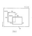
- Figure 2 shows the pattern memory 20.
- the pattern memory has storage locations that correspond to dots of two-dimensional image in one-to-one relation, and is area-specifiable by horizontal and vertical positions.
- the coordinate of upper left corner of the pattern memory is made (0, 0)
- the source area S including an image to be move-processed and the destination area D are made rectangular, each of which areas is to be specified by the coordinate of its upper left corner, the horizontal width and the vertical height.
- the source area S is indicated by the coordinate of upper left corner (X0, YO), the width XOL and the height YOL, the destination area D by the coordinate of upper left corner (Xl, Y1), the width X1L and the height YlL. In this example, it is assumed that the source area S is rotated by 90° to the left and moved to the destination D.
- the move processing according to the present invention follows such principle that the positions of source area S and destination area D are compared from four directions of top, bottom, right and left to determine for each direction whether there is any processable region included in the destination area D but not included in the source area S, and, when such processable region exists, the image data in a corresponding region of the source area is moved the processable region.
- the search for the processable region in the destination area D is performed in the order from the left side, the top side, the right side to the bottom side.
- the side region of the area S selected corresponding to each side region of the area D depends on the rotation angle as shown in Table 1.
- the side regions of area D are searched in the order of left side, upper side, right side and lower side. If a processable side region is found, the image data in a corresponding side region of the area S is rotated by the specified rotation angle, and written in the area D.
- the areas S and D exclusive of the move-processed portions are redefined as new source area S and destination area D.
- the side regions of the redefined destination area D are again searched in the sequence of left, upper, right and lower sides, and similar move processing, redefinition, and search for side regions are repeated. Therefore, the image data in the area S is transferred to the area D through a multi-cycle operation.
- the image data is processed in blocks of 16 x 16 bits. Therefore, the region S is moved by 16-bit length.
- the size of the unit processing block may be arbitrary. If the unit block is made smaller, it can attain finer movement, but takes longer processing time. In this example, it is selected to be 16 x 16 bits by balancing the processing time with the movement accuracy actually required.
- Figures 3 - 7 show various examples to move the area S to the area D by rotating it by 90° counterclockwise.
- Small squares divided in rows and columns of the areas S and D indicate the data blocks of 16 x 16 bits.
- Figure 3A in the search for the side regions of area D, first it is determined that the left side has a processable side region included in the area D but not included in the area S, and the top blocks A - F of the area S are rotated by 90° to the left, and written into the area D ( Figure 3A).
- the regions exclusive of the processed blocks A - F are redefined as new areas S and D, and the side regions of area D are again searched from the left side. Again, a processable side region is found in the left side, and the blocks G - L in the top side of area S are written into the area D ( Figure 3B).
- Figure 4 shows an example in which the areas S and D are partially overlapped. The process is the same as that for Figure 3.
- Figure 5 shows another example in which the areas S and D are partially overlapped.
- the left side region is found, and the blocks A - F and G - L are written into the region D.
- the next cycle C
- the processable side region is found in the comparison for the top side, and the blocks RX are written (D).
- the next cycle E
- any side region is not found in the left, the top and the right sides, but in the bottom side, and the blocks MS are written.
- the writing of the blocks MS causes an empty region in the left side of area D (F)
- the blocks N - Q are written into the left side region in the next cycle (G).
- the movement of blocks N - Q causes an empty region in the upper side (H), and the block W is written.
- the entire area S is transferred to the area D by repeating the cycles (J), (K) and (L).
- the outer blocks are subjected to periphery rotation process and a square exclusive of the processed is redefined. If the redefined square has a side consisting of blocks, such steps are repeated so that the periphery rotation process is again performed, and that the redefinition is performed. If one block remains, the one block rotation process is conducted. If no block remains, the process terminates at that moment.
- the periphery process is attained by saving the block b in the save memory as in (J), moving the block d to the location of block b, moving the block t to the location of block d and the block r to the location of block t, moving the block b in the save memory to the location of block r, then saving the block c in the save memory as in (K) to move the blocks 1, s and j to the locations of blocks c, 1 and s, respectively, and finally moving the block c in the save memory to the location of block j.
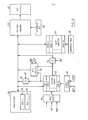
- FIG. 8 shows an embodiment wherein the present invention is applied to a CRT graphic display.
- Microprocessor 30 includes first register 32 holding the coordinates of source area S (X0, YO), XOL and Y01, and second register 34 holding the coordinates of destination area D (Xl, Yl), X1L and YlL.
- Pattern memory 20 serving as a refresh memory stores the dot pattern of the two-dimensional image to be displayed. The pattern data are read corresponding to the raster scanning of the CRT and displayed.
- the processor 30 reads and writes the pattern memory 20 by 16-bit words, and accesses the pattern memory 20 by providing XY addresses of 16-bit word to be accessed to address register 38.
- Rotating array 42 is used to temporarily store one block data (sixteen 16-bit words) read from the area S, and to rotate them by a specified rotating angle.
- the rotating array 42 consists of sixteen shift registers SRI - SR16 that can load and fetch 16 word bits in parallel. Sixteen 16-bit words read from the pattern memory are sequentially loaded in the shift registers SRI - SR16 under the control of register selecting circuit 44.
- the rotating array 42 can parallelly output 16 bits at a corresponding bit location from the right of the array 42 under the control of shift control circuit 46.
- sixteen words stored in the rotating array 42 are sequentially read from the shift registers SRI - SR16 under the control of the register selecting circuit 44, fed to a data bus through gate G 48, and written into the area D. If the rotation is 90° to the left, 16-bit words shifted from the right of the rotating array 42 are written into the area D through gate G 52. For 180°, similar to 0°, the words are fetched from the top of the array 42, while for 270° to the left, they are read from the right of the array 42 under the control of the shift control circuit 46.
- the orientation of word is required to be made opposite to that in 0° and 90°, and thus the 16-bit words from the array 42 are fed to bit switch circuit 50, where bits 1 - 16 are converted to bits 16 - 1 and fed to the data bus.
- Save memory 54 is a memory having a storage capacity for one block, and is accessed by address register 56 under the control of the processor.
- the save memory 54 is used for temporarily storing data for one block in the periphery processing of a square as described in connection with Figure 7.
- Figure 9 exemplifies a process in which blocks A, B, C ... in the top side of area S are written into the left side region of area D after rotating them by 90° to the left.
- the address of the upper left corner of block A in the area S, or the address of the uppermost 16-bit word of block A is (X0, YO)
- sixteen words in the block A are sequentially read by fixing the X address and changing the Y address from YO to YO + 15, and are parallelly loaded in the shift registers SR1 - SR16 of the rotating array 42.
- the data in the rotating array 42 is shifted out by the right shift.
- the 16-bit word at the sixteenth bit location of the rotating array 42 is written into the word location at address (Xl, Yl + YlL - 15), the 16-bit word at the fifteenth bit location being written into the word location at address (Xl, Y1 + Y1L - 14), then the 16-bit word at the second bit location being written into the word location at address (Xl, Yl + Y1L - 1), the 16-bit word at the first bit location being written into the word location at address (X1, Y1 + Y1L).
- the block b is stored in the save memory 54, the block d being loaded in the rotating array 42 and written into the location of block b through rotation of 90° counterclockwise, similarly the blocks t and r being sequentially read to the rotating array 42 and written into the locations of blocks d and t, finally the block b in the save memory being loaded in the rotating array 42 and written into the location of block r through rotation of 90° to the left.
- Figure 7 (K) a similar process is performed by saving the block c.
- the rotating process for one block k finally left is performed by loading the block k into the rotating array 42, and by writing it into the same block location through 90° rotation to the left.
- Figure 10 shows a program flowchart for the rotation of 90° to the left.
- locations (X0, YO), XOL, YOL, (X1, Yl), and XlL, Y1L of the areas S and D are set as in Table 2.
- the setting of the area D is common regardless of the rotation angle.
- the embodiment accesses the pattern memory with the XY addressing, but the linear addressing that assigns continuous addresses to words or unit access data may also be used.
- the rotating array is shown as one at the upper side of which the load/fetch is performed, and from the right of which the shifting-out is performed, such arrangement may be used that the fetch is performed from the lower side of the array, that the shifting-out can be made from the left of the array, or that the shifting can be performed in both left and right directions. According to this, the direction of increase and decrease of Y addresses will be selected in the writing of the pattern memory.
- the search for the side region of the area D is not limited to the sequence of left, top, right and bottom, but may be performed in any sequence.
- the pattern memory contains a plurality of images, and a rectangular source area S surrounding a processed image overlaps another image, the processed image may be moved in a plurality of steps by dividing it into a plurality of image sections, for each of which a source area is set, otherwise, it would also be possible to perform the move processing by specifying the coordinates for the source and the destination areas in a form of partially notched rectangular, although the program becomes somewhat complicated.
- the move process can be performed by a common scheme of determining the processable region of the destination area regardless of whether the move processing to be performed accompanies rotation or not, the positional relationship between the source and the destination areas, or the rotation angle, the control can be significantly simplified, and it is economical because a save memory with large storage capacity is not required.
Abstract
Description
- This invention relates to an image processing system, and more particularly to an image processing system for move-processing images such as characters or graphics. This invention can be utilized in an image processing device such as a CRT graphic display using raster scanning or an image scanner/printer.
- The image processing device such as the CRT graphic display usually uses ¡a so-called bit-mapped pattern memory that stores the dot pattern of a two-dimensional image to be displayed or reproduced. The pattern memory has storage locations corresponding to the image to be displayed or reproduced, and reproduces the image by sequentially reading line dot information in synchronization with raster or line scanning of the display or printer. The image processing device often requires to move the image being displayed. The image is moved without or with rotation.
- One of basic methods to move the image is to rewrite the content of pattern memory, wherein, in the past, rewriting of the dot pattern is usually performed by providing a save memory with storage capacity similar to that of the pattern memory, into which data in the pattern memory is once transferred, and then written again in the pattern memory. Although this method can be applied to any move processing, it is uneconomical because it requires a save memory with a large capacity.
- The Japanese Laid-open Patent No. 16485/82 discloses an image display device that is arranged to rotate and move display patterns by changing the timing of pattern memory addressing relative to that of raster scanning. According to this technique, there is such advantage that the rotation and movement of display pattern can be performed without rewriting the content of pattern memory one by one. However, if different move processing is performed for a plurality of display patterns on the same screen, it is required to provide a separate pattern memory and address converting circuit for each display pattern, thus requiring a large quantity of hardware.
- The Japanese Laid-open Patent No. 135984/82 discloses a display device that divides a pattern memory into small blocks of rows and columns, saves one block of the display pattern in a save memory in rotating the display pattern, moves into this emptied block the block to be moved to this block after the rotation, and causes the display pattern to rotate by repeating similar steps. Although this technique attains to rotate the display pattern only by using a save memory with the smaller capacity for one block, it is limited to rotation around the center of"pattern, and cannot be applied to image processing with movement.
- In addition, in cases where the image processing is performed by program control, a separate program is usually provided for each processing to be performed, for example, for movement without rotation, movement with rotation, or a case of 90°, 180° or 270° if the rotation is accompanied. Each program is called according to the processing. However, this method needs an enormous amount of programs, and complicates the control. If only a single program is provided, regardless of the contents of processing being performed, the control can be simplified, and the cost can be lowered.
- As described, the conventional image processing technique requires the save memory with a large capacity and the special hardware, otherwise it has narrow application and requires an enormous amount of programs.
- Therefore, an object of the invention is to provide an image processing system that can simply and economically perform the image processing by using a common control regardless of the content of move processing.
- The invention as claimed solves this problem in an advantageous manner. It performs the move processing by rewriting image data of two-dimensional dot patterns stored in the pattern memory. The move processing is performed in an angular relation of
n x 90° (n = 0, 1, 2 and 3) relative to a source image. In the move processing, specified is the type of processing to be performed, namely the movement without rotation, the movement with rotation of 90°, the movement with rotation of 180°, or the movement with rotation of 270°. Also specified are the location of a source area including an image to be moved, and the location of a destination area where the source area is to be positioned after the move processing. The locations of the source and the destination areas are compared from four direction of top, bottom, right and left to determine whether, in each direction, there is any processable region which is included in the destination area but not included in the source area. When the existence of such a processable region is detected, the image data in a selected region of the source area is transferred into said processable region. The region selected in the source area depends on the specified move processing. Then, the source and the destination areas exclusive of the move-processed portions are redefined as new source and destination areas, which are then determined for said processable region. Similar operations are repeated. - According to the invention, since the image processing can be performed by such a common algorithm that determination is made in four directions as to whether there is any processable region in the destination area, and that, when the existence of a processable region is determined, the image data in a corresponding region of the source area is transferred to the processable region. The basic portion of the program control for the image processing can be made common regardless of whether the move accompanies rotation or not, the positional relationship between the source and the destination area, or the rotation angle, so that it is possible to make the control simple and the cost low. Control which depends on the content of move processing is required only in a portion that performs the move processing by selecting the corresponding region from the source area according to the rotation angle, and in a portion that performs area redefinition according to the move processing. In addition, the transfer of image data can be performed in small data blocks, and does not require a save memory of large capacity.
- The following describes embodiments of the invention in connection with the appended drawings, in which
- Figure 1 shows the configuration of the invention;
- Figure 2 shows a pattern memory;
- Figures 3 - 7 show various processing examples of movement with 90° rotation to the left;
- Figure 8 shows an embodiment of the invention;
- Figure 9 exemplifies the operation of movement with 90° rotation to the left; and
- Figure 10 shows a program flowchart for the embodiment of Figure 8.
- Figure 1 shows the configuration of the invention, wherein first register means 10 holds positional data of a source area containing a two-dimensional dot pattern image in
pattern memory 20 to be move-processed, while second register means 12 holds positional data of a destination area where the source area is to be transferred. Determining means 14 compares the positional relations between the source and the destination areas from four directions of top, bottom, right and left based upon the positions held in the first and the second register means to determine, for each direction, whether there is any processable region included in the destination area but not included in the source area, and, when it is determined that there exists such processable region in any one direction, generates a signal indicating the existence of a processable region relating to said direction. Process specifying means 16 specifies the type of process to be performed (movement without rotation, movement with rotation of 90°, movement with rotation of 180°, or movement with rotation of 270°). Move-processing means 18 is responsive to the signal from the determining means, and, in accordance with the process specified by theprocess specifying means 16, reads the image data in a selected region of the source area and writes it in the determined processable region of the destination area. Resetting means 22 redefines portions of the source and the destination areas exclusive of the move-processed portions as new source and destination areas and sets their positional data in the first 10 and the second 12 registers to cause thedetermining means 14 to perform the determination for these new source and destination areas. - Now, examples of move processing are described by referring to Figures 2 - 7. Figure 2 shows the
pattern memory 20. The pattern memory has storage locations that correspond to dots of two-dimensional image in one-to-one relation, and is area-specifiable by horizontal and vertical positions. In this example, the coordinate of upper left corner of the pattern memory is made (0, 0), while the source area S including an image to be move-processed and the destination area D are made rectangular, each of which areas is to be specified by the coordinate of its upper left corner, the horizontal width and the vertical height. The source area S is indicated by the coordinate of upper left corner (X0, YO), the width XOL and the height YOL, the destination area D by the coordinate of upper left corner (Xl, Y1), the width X1L and the height YlL. In this example, it is assumed that the source area S is rotated by 90° to the left and moved to the destination D. - The move processing according to the present invention follows such principle that the positions of source area S and destination area D are compared from four directions of top, bottom, right and left to determine for each direction whether there is any processable region included in the destination area D but not included in the source area S, and, when such processable region exists, the image data in a corresponding region of the source area is moved the processable region. In this example, the search for the processable region in the destination area D is performed in the order from the left side, the top side, the right side to the bottom side.
- If (X1 - XO) < 0, then it is determined that the left side of the area D has a processable side region included in the area D but not included in the area S.
- If (Y1 - YO) < 0, then it is determined that the top side of the area D has a processable side region included in the area D but not included in the area S.
- If (XO + XOL) - (X1 + X1L) < 0, then it is indicated that the right side of the area D has such a processable side region.
- If (YO + YOL) - (Y1 + Y1L) < 0, then it is indicated that the bottom side of the area D has such a processable side region.
- The side region of the area S selected corresponding to each side region of the area D depends on the rotation angle as shown in Table 1.

- The side regions of area D are searched in the order of left side, upper side, right side and lower side. If a processable side region is found, the image data in a corresponding side region of the area S is rotated by the specified rotation angle, and written in the area D. The areas S and D exclusive of the move-processed portions are redefined as new source area S and destination area D. The side regions of the redefined destination area D are again searched in the sequence of left, upper, right and lower sides, and similar move processing, redefinition, and search for side regions are repeated. Therefore, the image data in the area S is transferred to the area D through a multi-cycle operation.
- In this example, the image data is processed in blocks of 16 x 16 bits. Therefore, the region S is moved by 16-bit length. The size of the unit processing block may be arbitrary. If the unit block is made smaller, it can attain finer movement, but takes longer processing time. In this example, it is selected to be 16 x 16 bits by balancing the processing time with the movement accuracy actually required.
- Figures 3 - 7 show various examples to move the area S to the area D by rotating it by 90° counterclockwise. Small squares divided in rows and columns of the areas S and D indicate the data blocks of 16 x 16 bits. In case of Figure 3, in the search for the side regions of area D, first it is determined that the left side has a processable side region included in the area D but not included in the area S, and the top blocks A - F of the area S are rotated by 90° to the left, and written into the area D (Figure 3A). The regions exclusive of the processed blocks A - F are redefined as new areas S and D, and the side regions of area D are again searched from the left side. Again, a processable side region is found in the left side, and the blocks G - L in the top side of area S are written into the area D (Figure 3B).
- After redefinition, the search is again performed from the left side of area D. However, in this cycle, no left side region is found, but a processable side region is found in the next comparison for the top side, and the blocks RX of region S are written into the top region of area D (Figure 3C). Then, by repeating the operation after the redefinition, the processable side region is found in the comparison for the top region in each cycle, and the blocks PV, OU, NT and MS are sequentially written into the area D to terminate the process.
- Figure 4 shows an example in which the areas S and D are partially overlapped. The process is the same as that for Figure 3.
- Figure 5 shows another example in which the areas S and D are partially overlapped. In each of the cycles (A) and (B), the left side region is found, and the blocks A - F and G - L are written into the region D. In the next cycle (C), because an empty region occurs in the top side of area D by the movement of the blocks G - L, the processable side region is found in the comparison for the top side, and the blocks RX are written (D). In the next cycle (E), any side region is not found in the left, the top and the right sides, but in the bottom side, and the blocks MS are written. Because the writing of the blocks MS causes an empty region in the left side of area D (F), the blocks N - Q are written into the left side region in the next cycle (G). The movement of blocks N - Q causes an empty region in the upper side (H), and the block W is written. Similarly the entire area S is transferred to the area D by repeating the cycles (J), (K) and (L).
- The processing actually caused depends on the shape, the size and the positional relationship of the areas S and D. There may happen the case where a square is finally left depending on the overlapping condition. Figure 6 shows an example in which one block is left, Figure 7 another example in which a square consisting of a plurality of blocks is left. Since the intermediate processes until the square is left is apparent from the above description and the drawing, they are omitted herein. In case where one block T remains as shown in Figure 6 (I), it is sufficient to read the block T, to rotate it by 90° to the left, and to write it into the same location.
- In case where a square of which one side has the length of a plurality of blocks is left, the outer blocks are subjected to periphery rotation process and a square exclusive of the processed is redefined. If the redefined square has a side consisting of blocks, such steps are repeated so that the periphery rotation process is again performed, and that the redefinition is performed. If one block remains, the one block rotation process is conducted. If no block remains, the process terminates at that moment. In case of Figure 7, the periphery process is attained by saving the block b in the save memory as in (J), moving the block d to the location of block b, moving the block t to the location of block d and the block r to the location of block t, moving the block b in the save memory to the location of block r, then saving the block c in the save memory as in (K) to move the
blocks 1, s and j to the locations of blocks c, 1 and s, respectively, and finally moving the block c in the save memory to the location of block j. - Figure 8 shows an embodiment wherein the present invention is applied to a CRT graphic display.
Microprocessor 30 includesfirst register 32 holding the coordinates of source area S (X0, YO), XOL and Y01, andsecond register 34 holding the coordinates of destination area D (Xl, Yl), X1L and YlL.Pattern memory 20 serving as a refresh memory stores the dot pattern of the two-dimensional image to be displayed. The pattern data are read corresponding to the raster scanning of the CRT and displayed. Theprocessor 30 reads and writes thepattern memory 20 by 16-bit words, and accesses thepattern memory 20 by providing XY addresses of 16-bit word to be accessed to addressregister 38. - Rotating
array 42 is used to temporarily store one block data (sixteen 16-bit words) read from the area S, and to rotate them by a specified rotating angle. Therotating array 42 consists of sixteen shift registers SRI - SR16 that can load and fetch 16 word bits in parallel. Sixteen 16-bit words read from the pattern memory are sequentially loaded in the shift registers SRI - SR16 under the control of register selecting circuit 44. In addition, the rotatingarray 42 can parallellyoutput 16 bits at a corresponding bit location from the right of thearray 42 under the control ofshift control circuit 46. - If the rotating angle is 0°, sixteen words stored in the
rotating array 42 are sequentially read from the shift registers SRI - SR16 under the control of the register selecting circuit 44, fed to a data bus throughgate G 48, and written into the area D. If the rotation is 90° to the left, 16-bit words shifted from the right of therotating array 42 are written into the area D throughgate G 52. For 180°, similar to 0°, the words are fetched from the top of thearray 42, while for 270° to the left, they are read from the right of thearray 42 under the control of theshift control circuit 46. However-?-for 180° and 270°, the orientation of word is required to be made opposite to that in 0° and 90°, and thus the 16-bit words from thearray 42 are fed to bitswitch circuit 50, where bits 1 - 16 are converted to bits 16 - 1 and fed to the data bus. - Save
memory 54 is a memory having a storage capacity for one block, and is accessed byaddress register 56 under the control of the processor. The savememory 54 is used for temporarily storing data for one block in the periphery processing of a square as described in connection with Figure 7. - Figure 9 exemplifies a process in which blocks A, B, C ... in the top side of area S are written into the left side region of area D after rotating them by 90° to the left. Assuming that the address of the upper left corner of block A in the area S, or the address of the uppermost 16-bit word of block A is (X0, YO), sixteen words in the block A are sequentially read by fixing the X address and changing the Y address from YO to YO + 15, and are parallelly loaded in the shift registers SR1 - SR16 of the
rotating array 42. In case of 90° rotation to the left, the data in therotating array 42 is shifted out by the right shift. Since the block A is to be written in the lower left block of area D with its address of the upper left corner being (X1, YlL - 15), the 16-bit word at the sixteenth bit location of therotating array 42 is written into the word location at address (Xl, Yl + YlL - 15), the 16-bit word at the fifteenth bit location being written into the word location at address (Xl, Y1 + Y1L - 14), then the 16-bit word at the second bit location being written into the word location at address (Xl, Yl + Y1L - 1), the 16-bit word at the first bit location being written into the word location at address (X1, Y1 + Y1L). - Similarly, when the block B is moved, it is sufficient to read sixteen words in the block B by making X address XO + 1, to load them int the rotating
array 42, and to write them into corresponding addresses of area D (X address = Xl, Y address = Yl + Y1L - 31 - Yl + YlL - 16). The same rules apply for others. - In the case of periphery processing, for example, in the case of Figure 7 (J), the block b is stored in the
save memory 54, the block d being loaded in therotating array 42 and written into the location of block b through rotation of 90° counterclockwise, similarly the blocks t and r being sequentially read to therotating array 42 and written into the locations of blocks d and t, finally the block b in the save memory being loaded in therotating array 42 and written into the location of block r through rotation of 90° to the left. Then, in Figure 7 (K), a similar process is performed by saving the block c. The rotating process for one block k finally left is performed by loading the block k into therotating array 42, and by writing it into the same block location through 90° rotation to the left. - Figure 10 shows a program flowchart for the rotation of 90° to the left. When the rotating processing is started (Block 60), XOL = 0 or YOL = 0 is checked (Block 62). If "YES", it means that there exists no area S to be move-processed, and the processing ends (Block 76). If "NO", it is checked for area S = area D, that is, whether there exists a square where area S completely overlaps area D (Block 64). If "NO", the existence of side region is sequentially checked for the left side (Xl X0 < 0 ?), the top side (Yl -
YO < 0 ?), the right side { (X0 + XOL) - (X1 + XIL) < 0} and the bottom side {(YO + YOL) - (Yl + Y1L) < 0} of the area D (Blocks 66 - 72). If no side region is found in the Blocks 66 - 72, it is an error (Block 74). If a side region is found, the move processing is performed for one block row or column of the area S (Blocks 88 - 94), after which the areas exclusive of the processed blocks are redefined as new source area S and destination D, and X and Y coordinates at the upper left, the width and the height of these areas are reset in theregisters 32 and 34 (Blocks 96 - 102). After resetting, the operation returns to the start and repeats the process. If area S = area D, check is made for XOL = YOL = 1, that is, whether the remaining square consists of a single block (Block 78). If it is a single block, the single block rotation process is performed (Block 80), and the redefinition is made (Block 84). As the result of redefinition, in the next cycle, XOL = YOL = 0 will be detected inBlock 62, and the operation ends. If XOL = Y0L ≠ 1, the periphery processing is performed (Block 82), the area S and D exclusive of the periphery-processed blocks being redefined (Block 86), the operation returning to the start. - In the redefinition after one block row or column is moved, locations (X0, YO), XOL, YOL, (X1, Yl), and XlL, Y1L of the areas S and D are set as in Table 2. The setting of the area D is common regardless of the rotation angle.

- Although the move processing for 0°, 180° and 270° are not described in detail, it will be apparent because it is sufficient to perform the side region processing for the left side, the top side, the right side and the bottom side of the area D in accordance with Table 1.
- Although specific examples have been described above, various modifications may be made within the scope of the invention. For example, the embodiment accesses the pattern memory with the XY addressing, but the linear addressing that assigns continuous addresses to words or unit access data may also be used. In addition, although the rotating array is shown as one at the upper side of which the load/fetch is performed, and from the right of which the shifting-out is performed, such arrangement may be used that the fetch is performed from the lower side of the array, that the shifting-out can be made from the left of the array, or that the shifting can be performed in both left and right directions. According to this, the direction of increase and decrease of Y addresses will be selected in the writing of the pattern memory. In addition, the search for the side region of the area D is not limited to the sequence of left, top, right and bottom, but may be performed in any sequence. Furthermore, if the pattern memory contains a plurality of images, and a rectangular source area S surrounding a processed image overlaps another image, the processed image may be moved in a plurality of steps by dividing it into a plurality of image sections, for each of which a source area is set, otherwise, it would also be possible to perform the move processing by specifying the coordinates for the source and the destination areas in a form of partially notched rectangular, although the program becomes somewhat complicated.
- According to the invention, since the move process can be performed by a common scheme of determining the processable region of the destination area regardless of whether the move processing to be performed accompanies rotation or not, the positional relationship between the source and the destination areas, or the rotation angle, the control can be significantly simplified, and it is economical because a save memory with large storage capacity is not required.
Claims (4)
Applications Claiming Priority (2)
| Application Number | Priority Date | Filing Date | Title |
|---|---|---|---|
| JP59084166A JPS60231235A (en) | 1984-04-27 | 1984-04-27 | Image processing system |
| JP84166/84 | 1984-04-27 |
Publications (3)
| Publication Number | Publication Date |
|---|---|
| EP0159461A2 true EP0159461A2 (en) | 1985-10-30 |
| EP0159461A3 EP0159461A3 (en) | 1986-07-16 |
| EP0159461B1 EP0159461B1 (en) | 1989-08-02 |
Family
ID=13822905
Family Applications (1)
| Application Number | Title | Priority Date | Filing Date |
|---|---|---|---|
| EP85100072A Expired EP0159461B1 (en) | 1984-04-27 | 1985-01-04 | Image processing system |
Country Status (5)
| Country | Link |
|---|---|
| US (1) | US4716533A (en) |
| EP (1) | EP0159461B1 (en) |
| JP (1) | JPS60231235A (en) |
| CA (1) | CA1228437A (en) |
| DE (1) | DE3572054D1 (en) |
Cited By (5)
| Publication number | Priority date | Publication date | Assignee | Title |
|---|---|---|---|---|
| EP0221418A2 (en) * | 1985-10-31 | 1987-05-13 | International Business Machines Corporation | Improved method for rotating a binary image |
| EP0239119A2 (en) * | 1986-03-27 | 1987-09-30 | Nec Corporation | Information transferring method and apparatus of transferring information from one memory area to another memory area |
| EP0247622A2 (en) * | 1986-05-30 | 1987-12-02 | Oki Electric Industry Company, Limited | Character pattern converting circuit |
| GB2183067B (en) * | 1985-11-13 | 1990-04-25 | Sony Corp | Data processing |
| US5239628A (en) * | 1985-11-13 | 1993-08-24 | Sony Corporation | System for asynchronously generating data block processing start signal upon the occurrence of processing end signal block start signal |
Families Citing this family (19)
| Publication number | Priority date | Publication date | Assignee | Title |
|---|---|---|---|---|
| JPH0762794B2 (en) * | 1985-09-13 | 1995-07-05 | 株式会社日立製作所 | Graphic display |
| US6697070B1 (en) | 1985-09-13 | 2004-02-24 | Renesas Technology Corporation | Graphic processing system |
| JPS6370381A (en) * | 1986-09-12 | 1988-03-30 | インターナショナル・ビジネス・マシーンズ・コーポレーション | Rotation of image data |
| JPS63225290A (en) * | 1987-03-14 | 1988-09-20 | 株式会社日立製作所 | Display control circuit |
| US5063526A (en) * | 1987-06-03 | 1991-11-05 | Advanced Micro Devices, Inc. | Bit map rotation processor |
| US4984152A (en) * | 1987-10-06 | 1991-01-08 | Bell Communications Research, Inc. | System for controlling computer processing utilizing a multifunctional cursor with decoupling of pointer and image functionalities in space and time |
| JPH077260B2 (en) * | 1987-11-20 | 1995-01-30 | 株式会社日立製作所 | Image data rotation processing apparatus and method thereof |
| JP2839891B2 (en) * | 1988-09-12 | 1998-12-16 | 株式会社日立製作所 | Printing control method |
| US4902919A (en) * | 1988-09-26 | 1990-02-20 | Motorola, Inc. | Inverting latching bootstrap driver with Vdd *2 booting |
| US5052834A (en) * | 1989-04-14 | 1991-10-01 | International Business Machines Corporation | System and method of printing sideways |
| AU5824690A (en) * | 1989-06-02 | 1991-01-07 | Atari Corporation | System and method for video display object detection |
| US5309548A (en) * | 1989-09-21 | 1994-05-03 | Canon Kabushiki Kaisha | Pattern generating method and apparatus |
| US5204916A (en) * | 1991-08-06 | 1993-04-20 | Eastman Kodak Company | Tile-oriented technique for collectively performing image rotation, scaling and digital halftone screening |
| US5463720A (en) * | 1992-09-28 | 1995-10-31 | Granger; Edward M. | Blue noise based technique for use in a halftone tile oriented screener for masking screener induced image artifacts |
| US6226016B1 (en) | 1996-02-05 | 2001-05-01 | Seiko Epson Corporation | Display apparatus and method capable of rotating an image by 180 degrees |
| US5734875A (en) * | 1996-02-05 | 1998-03-31 | Seiko Epson Corporation | Hardware that rotates an image for portrait-oriented display |
| US6262751B1 (en) | 1998-10-26 | 2001-07-17 | Seiko Epson Corporation | Hardware rotation of an image on a computer display |
| US6639603B1 (en) | 1999-04-21 | 2003-10-28 | Linkup Systems Corporation | Hardware portrait mode support |
| US7376286B2 (en) * | 2002-09-18 | 2008-05-20 | Nxp B.V. | Block-based rotation of arbitrary-shaped images |
Citations (1)
| Publication number | Priority date | Publication date | Assignee | Title |
|---|---|---|---|---|
| US4168488A (en) * | 1977-09-12 | 1979-09-18 | International Business Machines Corporation | Image rotation apparatus |
Family Cites Families (4)
| Publication number | Priority date | Publication date | Assignee | Title |
|---|---|---|---|---|
| US4267573A (en) * | 1978-06-14 | 1981-05-12 | Old Dominion University Research Foundation | Image processing system |
| FR2504673A1 (en) * | 1981-04-27 | 1982-10-29 | Thomson Csf | CARTOGRAPHIC INDICATOR RECORDED ON PHOTOGRAPHIC FILM |
| JPS59101969A (en) * | 1982-12-01 | 1984-06-12 | Dainippon Screen Mfg Co Ltd | Method and device for processing data of binary picture pattern |
| US4533941A (en) * | 1983-01-14 | 1985-08-06 | Coulter Systems Corporation | Method and apparatus for half-tone reproduction of a varying tone original image |
-
1984
- 1984-04-27 JP JP59084166A patent/JPS60231235A/en active Granted
-
1985
- 1985-01-04 EP EP85100072A patent/EP0159461B1/en not_active Expired
- 1985-01-04 DE DE8585100072T patent/DE3572054D1/en not_active Expired
- 1985-02-26 CA CA000475188A patent/CA1228437A/en not_active Expired
- 1985-04-23 US US06/726,263 patent/US4716533A/en not_active Expired - Lifetime
Patent Citations (1)
| Publication number | Priority date | Publication date | Assignee | Title |
|---|---|---|---|---|
| US4168488A (en) * | 1977-09-12 | 1979-09-18 | International Business Machines Corporation | Image rotation apparatus |
Cited By (8)
| Publication number | Priority date | Publication date | Assignee | Title |
|---|---|---|---|---|
| EP0221418A2 (en) * | 1985-10-31 | 1987-05-13 | International Business Machines Corporation | Improved method for rotating a binary image |
| EP0221418A3 (en) * | 1985-10-31 | 1989-06-07 | International Business Machines Corporation | Improved method for rotating a binary image |
| GB2183067B (en) * | 1985-11-13 | 1990-04-25 | Sony Corp | Data processing |
| US5239628A (en) * | 1985-11-13 | 1993-08-24 | Sony Corporation | System for asynchronously generating data block processing start signal upon the occurrence of processing end signal block start signal |
| EP0239119A2 (en) * | 1986-03-27 | 1987-09-30 | Nec Corporation | Information transferring method and apparatus of transferring information from one memory area to another memory area |
| EP0239119A3 (en) * | 1986-03-27 | 1990-02-07 | Nec Corporation | Information transferring method and apparatus of transferring information from one memory area to another memory area |
| EP0247622A2 (en) * | 1986-05-30 | 1987-12-02 | Oki Electric Industry Company, Limited | Character pattern converting circuit |
| EP0247622A3 (en) * | 1986-05-30 | 1990-04-04 | Oki Electric Industry Company, Limited | Character pattern converting circuit |
Also Published As
| Publication number | Publication date |
|---|---|
| EP0159461B1 (en) | 1989-08-02 |
| EP0159461A3 (en) | 1986-07-16 |
| CA1228437A (en) | 1987-10-20 |
| JPS60231235A (en) | 1985-11-16 |
| JPH0361228B2 (en) | 1991-09-19 |
| DE3572054D1 (en) | 1989-09-07 |
| US4716533A (en) | 1987-12-29 |
Similar Documents
| Publication | Publication Date | Title |
|---|---|---|
| EP0159461B1 (en) | Image processing system | |
| US4648049A (en) | Rapid graphics bit mapping circuit and method | |
| US4979738A (en) | Constant spatial data mass RAM video display system | |
| EP0197412B1 (en) | Variable access frame buffer memory | |
| US4670752A (en) | Hard-wired circuit for handling screen windows | |
| JPH06180685A (en) | Apparatus for writing into and reading out of multiple-bank frame-buffer random access port and method for improving writing speed of pixel into multiple-bank frame buffer into multiple-bank frame buffer | |
| EP0082746A2 (en) | Address generator | |
| US4570161A (en) | Raster scan digital display system | |
| US5371519A (en) | Split sort image processing apparatus and method | |
| JPS6325672B2 (en) | ||
| US4747042A (en) | Display control system | |
| US20030122837A1 (en) | Dual memory channel interleaving for graphics and MPEG | |
| JPS62166391A (en) | Cursor controller | |
| KR920003459B1 (en) | Image processing apparatus | |
| KR950020279A (en) | Graphics computer | |
| US5742298A (en) | 64 bit wide video front cache | |
| US5841446A (en) | Method and apparatus for address mapping of a video memory using tiling | |
| KR960003072B1 (en) | Font data processing apparatus | |
| US5416499A (en) | Bit map display controlling apparatus | |
| JPH09106374A (en) | Image memory device | |
| JP3296677B2 (en) | Drawing method and apparatus | |
| JPS63304293A (en) | Display memory control circuit | |
| JP2740197B2 (en) | Bitmap drawing device | |
| EP0473789A1 (en) | Bit map display controller | |
| JPH07118006B2 (en) | Image processing device |
Legal Events
| Date | Code | Title | Description |
|---|---|---|---|
| PUAI | Public reference made under article 153(3) epc to a published international application that has entered the european phase |
Free format text: ORIGINAL CODE: 0009012 |
|
| AK | Designated contracting states |
Designated state(s): DE FR GB IT |
|
| 17P | Request for examination filed |
Effective date: 19860225 |
|
| PUAL | Search report despatched |
Free format text: ORIGINAL CODE: 0009013 |
|
| AK | Designated contracting states |
Kind code of ref document: A3 Designated state(s): DE FR GB IT |
|
| 17Q | First examination report despatched |
Effective date: 19881010 |
|
| GRAA | (expected) grant |
Free format text: ORIGINAL CODE: 0009210 |
|
| AK | Designated contracting states |
Kind code of ref document: B1 Designated state(s): DE FR GB IT |
|
| REF | Corresponds to: |
Ref document number: 3572054 Country of ref document: DE Date of ref document: 19890907 |
|
| ET | Fr: translation filed | ||
| ITF | It: translation for a ep patent filed |
Owner name: IBM - DR. ARRABITO MICHELANGELO |
|
| PLBE | No opposition filed within time limit |
Free format text: ORIGINAL CODE: 0009261 |
|
| STAA | Information on the status of an ep patent application or granted ep patent |
Free format text: STATUS: NO OPPOSITION FILED WITHIN TIME LIMIT |
|
| 26N | No opposition filed | ||
| ITTA | It: last paid annual fee | ||
| PGFP | Annual fee paid to national office [announced via postgrant information from national office to epo] |
Ref country code: GB Payment date: 19931221 Year of fee payment: 10 |
|
| PGFP | Annual fee paid to national office [announced via postgrant information from national office to epo] |
Ref country code: FR Payment date: 19931222 Year of fee payment: 10 |
|
| PGFP | Annual fee paid to national office [announced via postgrant information from national office to epo] |
Ref country code: DE Payment date: 19931231 Year of fee payment: 10 |
|
| PG25 | Lapsed in a contracting state [announced via postgrant information from national office to epo] |
Ref country code: GB Effective date: 19950104 |
|
| GBPC | Gb: european patent ceased through non-payment of renewal fee |
Effective date: 19950104 |
|
| PG25 | Lapsed in a contracting state [announced via postgrant information from national office to epo] |
Ref country code: FR Effective date: 19950929 |
|
| PG25 | Lapsed in a contracting state [announced via postgrant information from national office to epo] |
Ref country code: DE Effective date: 19951003 |
|
| REG | Reference to a national code |
Ref country code: FR Ref legal event code: ST |