EP0145332A2 - Digital audio transmission - Google Patents
Digital audio transmission Download PDFInfo
- Publication number
- EP0145332A2 EP0145332A2 EP84307933A EP84307933A EP0145332A2 EP 0145332 A2 EP0145332 A2 EP 0145332A2 EP 84307933 A EP84307933 A EP 84307933A EP 84307933 A EP84307933 A EP 84307933A EP 0145332 A2 EP0145332 A2 EP 0145332A2
- Authority
- EP
- European Patent Office
- Prior art keywords
- sub
- bands
- band
- bits
- data bits
- Prior art date
- Legal status (The legal status is an assumption and is not a legal conclusion. Google has not performed a legal analysis and makes no representation as to the accuracy of the status listed.)
- Granted
Links
Images

Classifications
-
- H—ELECTRICITY
- H04—ELECTRIC COMMUNICATION TECHNIQUE
- H04M—TELEPHONIC COMMUNICATION
- H04M11/00—Telephonic communication systems specially adapted for combination with other electrical systems
- H04M11/06—Simultaneous speech and data transmission, e.g. telegraphic transmission over the same conductors
- H04M11/064—Data transmission during pauses in telephone conversation
-
- H—ELECTRICITY
- H04—ELECTRIC COMMUNICATION TECHNIQUE
- H04B—TRANSMISSION
- H04B1/00—Details of transmission systems, not covered by a single one of groups H04B3/00 - H04B13/00; Details of transmission systems not characterised by the medium used for transmission
- H04B1/66—Details of transmission systems, not covered by a single one of groups H04B3/00 - H04B13/00; Details of transmission systems not characterised by the medium used for transmission for reducing bandwidth of signals; for improving efficiency of transmission
- H04B1/667—Details of transmission systems, not covered by a single one of groups H04B3/00 - H04B13/00; Details of transmission systems not characterised by the medium used for transmission for reducing bandwidth of signals; for improving efficiency of transmission using a division in frequency subbands
Definitions
- This invention relates to transmission using sub-band coding, and particularly, though not exclusively, to multiplexing data and digitally coded audio for transmission.
- Sub-band coding is a coding technique in which a parent frequency band, usually speech, is divided into two or more sub-bands, the frequency range within each of which is separately encoded and transmitted.
- the main advantages of sub-band coding for example, over pulse code modulation (PCM) or adaptive differential pulse code modulation (ADPCM) are generally considered to be that:
- a method of coding a digital sub-band coded signal in which the number of bits allocated to the respective sub-bands is adaptively determined as a function of those bits which are always transmitted, whereby the coded signal may be decoded by reference only to the transmitted bits.
- ⁇ '!e provide a digital sub-band coder comprising filter means for dividing the input signal into two or more frequency sub-bands, and adaptive bit allocation means for adaptively determining the number of bits to be used for encoding each sub-band in dependence on the relative energy content of the sub-bands, characterised in that the bit allocation means is responsive only to those bits of each sub-band which are always transmitted.
- a further aspect of the invention provides a method of transmitting a digital data signal together with a digital sub-band coded signal which comprises comparing the energy contents different sub-bands and adaptively inserting data bits into a sub-band with a low energy content.
- apparatus to transmit digital sub-band encoded signals and digital data signals comprising means to divide an incoming frequency band into a plurality of sub-bands and means for encoding each sub-band separately, characterised in that the apparatus further comprises means to measure and compare the energy contents of the sub-bands and selectively insert data bits into a sub-band having a low energy envelope.
- the sub-bands may themselves be sub-bands of lower order sub-bands, or may be the only sub-bands into which the parent freauency band has been divided.
- the comparison may be made, for example, by subtracting the respective sub-band stepsizes, but is preferably made by determining their ratio.
- a sub-band coder for speech signals receives at an input 1, a speech signal which is assumed to be PCM coded at a sampling rate of 16kHz.
- the input frequency spectrum is divided into upper and lower sub-bands by high-pass and low-pass filters 2, 3, the two bands then being down-sampled to 8kHz in "decimators" 4,5.
- the signals at this point are assumed to be quantised to four-bit accuracy, in both bands, although in practice more bits would be used, not necessarily the same number in each band.
- An output multiplexer 6 is provided to assemble the output bits into suitable form for onward transmission from its output; it could be part of a t.d.m. system, or simply a parallel-to-serial converter. It has, by way of example, an 8-bit input. One bit of these eight is permanently assigned to transmission of an auxiliary data signal D; note however that this is incidental to the principle being illustrated in Figure 1.
- the corresponding decoder ( Figure 2) is essentially a mirror image of the transmitter, a demultiplexer 16 feeding the three most significant inputs of up-samplers 14, 15 which in turn supply interpolation filters 12,13 the outputs of which are added at 10 to form the decoded output 11.
- the selector 8 is controlled by a decision circuit 9 which determines which of the two least significant bits h O or 1 0 is to be transmitted. This decision is made as a function of the relative signal or energy content of the two channels, and the corresponding deselection (by a one-bit demultiplexer 18) at the decoder is controlled by a functionally identical decision circuit 19.
- the decoder decision circuit can accurately "track” operation of that in the coder, the decision circuits are in each case responsive only to the three most significant bits h 3 -h 1 , 1 3 -1 1 of the two channels.
- the decoder decision circuit does not, of course, have access to both h O and 1 0 ; nor does it "know” prior to making its decision, which of them it does have access to.
- the decision circuits 9, 19 serve to assess which channel has the higher energy content, so that the dropping of the least significant bit will occur in a channel where it makes the lesser noise contribution. Although it would be possible to do this on a sample-by-sample basis (where a simple comparator would suffice), for a practical system it would compare and average energy estimates formed over a period; this will be discussed further below.
- Figure 3 shows a modified version of the coder of Figure 1, where, of the eight available bits, four are allocated to each of the two channels, the auxiliary data D being adaptively inserted in the least significant bit position h O or l 0 of one of the two channels.
- the decision circuit 9' has two outputs x, y which are active when the ratio of the energy in the upper channel to that in the lower respectively exceeds a lower threshold or falls below a higher one, so that when it falls between the two thresholds, the data is inserted into both channels.
- a single decision threshold is used, as before. In this way, corruption of the data by errors in the decision, due to finite computational accuracy, or transmission errors, are reduced.
- the coder suitable for receiving a wide band speech input signal of 7kHz bandwidth sampled at 16kHz and transmitting it at 64kbit/s uses ADPCM (adaptive differential pulse code modulation). Differential coders normally suffer from an excessive signal-to-noise penalty if bits are deleted and to rectify this, an embedded ADPCM coding is used. Embedded coders are described in "Embedded DPCM for variable bit rate transmission", David J Goodman, IEEE Trans. Comm. Vol COM-28, No.7, July 1980, pp1040 to 1046. The encoder described there is not an adaptive coder (nor is it used for sub-band coding).
- an embedded DPCM coder solves the problem (with a small SNR penalty due to less accurate prediction and hence a higher quantiser step size and thus quantisation noise) in that any bits liable to be omitted on transmission are excluded from the predictor loop at both coder and decoder.
- the sub-band coder 1 comprises a digital filter 22 consisting of a high pass filter 22a and a low pass filter 22b which divides the digitally (eg PCM) encoded input signal at terminal 3 into two sub-bands, which are down sampled in respective down sampling circuits 24a and 24b of a "decimator" 24 from where they are supplied to ADPCM encoder 5 connected to the output of down sampler 4a, and ADPCM encoder 6 connected to the output of down sampler 4b.
- the ADPCM encoders 5 and 6 have code word outputs 7 and 8 respectively.
- the ADPCM encoders 5 and 6 also have outputs 9 and 10 providing a signal indicative of the stepsize to a decision circuit 31.
- the output of the decision circuit 31 is connected to data insertion circuits 32 and 33, and controls their operation in the manner explained below.
- the outputs of data insertion circuits 32 and 33 form the inputs of an 8bit multiplexer 34 whose output is the signal to be transmitted.
- the digital filter 2 comprises quadrature mirror filters (QMFs) which are used to split the input spectrum into two overlapping bands (0-4 kHz, and 4-8 kHz). Suitable filter constants are listed in Table 1. The signals contained in each of the two sub-bands are then applied to the respective down sampler 24a (4-8 kHz) and 24b (0-4 kHz) where they are down sampled to 8 kilo samples per second and applied to the two independent ADPCM coders 25 and 26 respectively.
- QMFs quadrature mirror filters
- ADPCM coders per se are known, and for the present purposes it will be sufficient to note that the encoding of the two sub-bands in ADPCM encoders 5 and 6 is not symmetric, in that the lower sub-band is encoded using ADPCM with a 5 bit robust Jayant quantiser (AQJ) and a fixed fourth order predictor optimised for 4 kHz band width speech.
- the higher sub-band (4-8 kHz) is encoded by a 3 bit robust AQJ with a fixed first order predictor.
- the lower and upper sub-bands are demultiplexed in demultiplexer 55 and are then processed in essentially the inverse order of that performed on encoding, with the components 42 to 53 being essentially the mirror images of the corresponding components 22 to 33 of the encoder.
- the 64 Kbit/s signal is demultiplexed, decoded, interpolated and processed by the receiver QMF bank to recover the 7 kHz bandwidth signal, the two channels being combined in an adder 43.
- the SBC encoder and decoder additionally include data insertion and data recovery circuits 32, 33 and 52, 53 respectively, as well as the data insertion and data recovery decision circuits 31 and 51.
- the 3 bit and 5 bit outputs of the ADPCM encoders 5 and 6 respectively are applied to the data insertion circuits 12 and 13 where a single data bit is inserted - into, and thus replaces the existing bit in, the fifth encoded (least significant) bit position for the lower channel output, or into the third encoded bit position for the upper channel, or into both, in accordance with the data insertion strategy described below.
- the output from the SBC coder 1 is configured either as 5 + (2 + D) or (4 + D) + 3, or (4 + D) + (2 + D), where D is the data bit.
- the decision circuits 31,51 are comparators which compare the adaptor stepsize (scaling factor) generated in the stepsize adapting circuits 46 and 47 of Figure 7, which is a block diagram of the ADPCM coders 25,26 and decoders 45,46.
- the data insertion decision strategy and the corresponding data recovery strategy operate on the following principles.
- the data channel selection strategy is determined as follows.
- a spectral envelope estimate that is essentially a measure for the energy content, is obtained for each sub-band signal and the estimates for the two channels are then compared to give a three way decision voiced (such as vowels), unvoiced (such as the syllable s) and intermediate.
- the upper channel (4-8 kHz) is selected for the data bit, and 5 bits are then available for accurate representation of the predominantly lower channel signal.
- the lower channel (0-4 kHz) is arranged to carry the data bit thus leaving 4 bits available for coding the speech signal in the lower band.
- the full 3 bits are then available in the upper channel for accurately coding the higher frequencies of the speech signal.
- the short term spectral envelope information for the data insertion decision is derived from the quantiser stepsize parameters for the two channels.
- This information is derived in a backward adaptive mode, using the robust Jayant algorithm, ie the stepsize parameter for the lower and upper channel quantisers respectively is given by and where Il(n) is the nth output codeword for the lower channel quantiser and Iu(n) is the output codeword from the upper channel quantiser.
- Ml(.) and Mu(.) are multiplier functions shown in table 1b for quantisers with various numbers of bits.
- y is a 'leakage factor' which is required in order to dissipate the effect of transmission errors.
- ⁇ is chosen to be 0.984.
- the decision as to which sub-band is to receive the data bit is determined as follows. First the scaled ratio of the lower and upper quantiser step-sizes is obtained as: where is a constant and V(n) is the time varying signal applied to the subsequent data bit assignment strategy.
- equation 5 is expressed in a logarithmic form:
- the transmitter implies (soft) decision thresholds, which cause the insertion of the data bit simultaneously into both sub-bands when v(n) falls between an upper and a lower threshold, u and 1.
- the decoder forms the comparison with a hard middle threshold, .
- the adaptive data insertion technique of the present invention was simulated in floating point Fortran on a mini computer and compared with a fixed data bit assignment technique, that is the technique where the data are multiplexed at all times into either the upper or the lower sub-band code words.
- a fixed data bit assignment technique that is the technique where the data are multiplexed at all times into either the upper or the lower sub-band code words.
- the finite precision limitations of an NEC ⁇ P0 7720 microprocessor such as is commonly used in speech coding transmitters and receivers, were simulated and facilities were also provided to inject random errors into the serialised output (the channel) of the sub-band coder.
- the afore-described is a simple yet potentially powerful technique for insertion, for example, 8 Kbit/s of data into a 56 Kbit/s SBC coded wideband speech channel.
- the technique described may be combined with for example adaptive prediction in the lower band, to increase the data carrying capacity beyond this.
- the present technique results in a noticeable reduction in the perceivable distortion.
Abstract
Description
- This invention relates to transmission using sub-band coding, and particularly, though not exclusively, to multiplexing data and digitally coded audio for transmission.
- Sub-band coding (SBC) is a coding technique in which a parent frequency band, usually speech, is divided into two or more sub-bands, the frequency range within each of which is separately encoded and transmitted. The main advantages of sub-band coding, for example, over pulse code modulation (PCM) or adaptive differential pulse code modulation (ADPCM) are generally considered to be that:
- a) the quantisation noise generated within each sub-band remains confined to that frequency range and on decoding does not mask low level speech sounds in other bands; and
- b) each sub-band signal may be coded according to the perceptual contribution that sub-band makes to the overall subjective quality.
- According to one aspect of the present invention, there is provided a method of coding a digital sub-band coded signal, in which the number of bits allocated to the respective sub-bands is adaptively determined as a function of those bits which are always transmitted, whereby the coded signal may be decoded by reference only to the transmitted bits.
- In another aspect \'!e provide a digital sub-band coder comprising filter means for dividing the input signal into two or more frequency sub-bands, and adaptive bit allocation means for adaptively determining the number of bits to be used for encoding each sub-band in dependence on the relative energy content of the sub-bands, characterised in that the bit allocation means is responsive only to those bits of each sub-band which are always transmitted.
- A further aspect of the invention provides a method of transmitting a digital data signal together with a digital sub-band coded signal which comprises comparing the energy contents different sub-bands and adaptively inserting data bits into a sub-band with a low energy content.
- In yet another aspect, we provide apparatus to transmit digital sub-band encoded signals and digital data signals, comprising means to divide an incoming frequency band into a plurality of sub-bands and means for encoding each sub-band separately, characterised in that the apparatus further comprises means to measure and compare the energy contents of the sub-bands and selectively insert data bits into a sub-band having a low energy envelope.
- Conveniently the comparison is made between two adjoining sub-bands. The sub-bands may themselves be sub-bands of lower order sub-bands, or may be the only sub-bands into which the parent freauency band has been divided.
- The comparison may be made, for example, by subtracting the respective sub-band stepsizes, but is preferably made by determining their ratio.
- The present invention will now be explained further by way of example and with reference to the accompanying drawings of which:
- Figures 1, 3 and 5 are schematic diagrams of SBC encoders incorporating the present invention;
- Figure 2, 4 and 6 are schematic diagrams of SBC decoders incorporating the present invention; and
- Figure 7 is a schematic diagram of an embedded ADPCM coder and decoder;
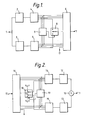
- Referring to Figure 1, a sub-band coder for speech signals receives at an
input 1, a speech signal which is assumed to be PCM coded at a sampling rate of 16kHz. The input frequency spectrum is divided into upper and lower sub-bands by high-pass and low-pass filters - An
output multiplexer 6 is provided to assemble the output bits into suitable form for onward transmission from its output; it could be part of a t.d.m. system, or simply a parallel-to-serial converter. It has, by way of example, an 8-bit input. One bit of these eight is permanently assigned to transmission of an auxiliary data signal D; note however that this is incidental to the principle being illustrated in Figure 1. - An adaptive allocation of the remaining seven available bits to the two channels is effected on the basis that one channel will be transmitted with 3-bit accuracy, the other 4-bit.· Thus the 3 most significant bits h3-h1, 13-11 of the two channels are permanently assigned to respective bit inputs of the
multiplexer 6, whilst the eighth input of the multiplexer receives, via aselector 8, the least significant bit h0 or 10 of a selected one of the two channels. - The corresponding decoder (Figure 2) is essentially a mirror image of the transmitter, a
demultiplexer 16 feeding the three most significant inputs of up-samplers supply interpolation filters - Returning to the coder of Figure 1, the
selector 8 is controlled by a decision circuit 9 which determines which of the two least significant bits hO or 10 is to be transmitted. This decision is made as a function of the relative signal or energy content of the two channels, and the corresponding deselection (by a one-bit demultiplexer 18) at the decoder is controlled by a functionallyidentical decision circuit 19. - So that the decoder decision circuit can accurately "track" operation of that in the coder, the decision circuits are in each case responsive only to the three most significant bits h3-h1, 13-11 of the two channels. The decoder decision circuit does not, of course, have access to both hO and 10; nor does it "know" prior to making its decision, which of them it does have access to.
- The
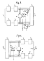
decision circuits 9, 19 serve to assess which channel has the higher energy content, so that the dropping of the least significant bit will occur in a channel where it makes the lesser noise contribution. Although it would be possible to do this on a sample-by-sample basis (where a simple comparator would suffice), for a practical system it would compare and average energy estimates formed over a period; this will be discussed further below. - Figure 3 shows a modified version of the coder of Figure 1, where, of the eight available bits, four are allocated to each of the two channels, the auxiliary data D being adaptively inserted in the least significant bit position hO or l0 of one of the two channels. As shown, however, the decision circuit 9' has two outputs x, y which are active when the ratio of the energy in the upper channel to that in the lower respectively exceeds a lower threshold or falls below a higher one, so that when it falls between the two thresholds, the data is inserted into both channels. In the receiver, a single decision threshold is used, as before. In this way, corruption of the data by errors in the decision, due to finite computational accuracy, or transmission errors, are reduced.
- A more practical version of the coder and decoder of Figures 2 and 3 will now be described; note however that much of what follows could also be applied to the coder and decoder of Figures 1 and 2.
- The coder, suitable for receiving a wide band speech input signal of 7kHz bandwidth sampled at 16kHz and transmitting it at 64kbit/s uses ADPCM (adaptive differential pulse code modulation). Differential coders normally suffer from an excessive signal-to-noise penalty if bits are deleted and to rectify this, an embedded ADPCM coding is used. Embedded coders are described in "Embedded DPCM for variable bit rate transmission", David J Goodman, IEEE Trans. Comm. Vol COM-28, No.7, July 1980, pp1040 to 1046. The encoder described there is not an adaptive coder (nor is it used for sub-band coding). Essentially, an embedded DPCM coder solves the problem (with a small SNR penalty due to less accurate prediction and hence a higher quantiser step size and thus quantisation noise) in that any bits liable to be omitted on transmission are excluded from the predictor loop at both coder and decoder.
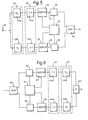
- The
sub-band coder 1 comprises adigital filter 22 consisting of ahigh pass filter 22a and alow pass filter 22b which divides the digitally (eg PCM) encoded input signal atterminal 3 into two sub-bands, which are down sampled in respective down sampling circuits 24a and 24b of a "decimator" 24 from where they are supplied toADPCM encoder 5 connected to the output of down sampler 4a, andADPCM encoder 6 connected to the output of down sampler 4b. TheADPCM encoders encoders decision circuit 31. The output of thedecision circuit 31 is connected todata insertion circuits data insertion circuits 8bit multiplexer 34 whose output is the signal to be transmitted. - The
digital filter 2 comprises quadrature mirror filters (QMFs) which are used to split the input spectrum into two overlapping bands (0-4 kHz, and 4-8 kHz). Suitable filter constants are listed in Table 1. The signals contained in each of the two sub-bands are then applied to the respective down sampler 24a (4-8 kHz) and 24b (0-4 kHz) where they are down sampled to 8 kilo samples per second and applied to the twoindependent ADPCM coders ADPCM encoders - In the receiver the lower and upper sub-bands are demultiplexed in
demultiplexer 55 and are then processed in essentially the inverse order of that performed on encoding, with thecomponents 42 to 53 being essentially the mirror images of thecorresponding components 22 to 33 of the encoder. - The 64 Kbit/s signal is demultiplexed, decoded, interpolated and processed by the receiver QMF bank to recover the 7 kHz bandwidth signal, the two channels being combined in an
adder 43. - The SBC encoder and decoder additionally include data insertion and
data recovery circuits recovery decision circuits - The 3 bit and 5 bit outputs of the
ADPCM encoders data insertion circuits - Thus the output from the
SBC coder 1 is configured either as 5 + (2 + D) or (4 + D) + 3, or (4 + D) + (2 + D), where D is the data bit. - In this embodiment, the
decision circuits stepsize adapting circuits ADPCM coders decoders - It is clearly desirable that the decision as to which channel receives the data bit should not require any transmission of side information to the receiver to provide correct demultiplexing. For this reason a backward adaptive data multiplexing strategy is employed where the multiplexing and demultiplexing data channel selection decision is derived from the transmit quantiser output code words and receiver input code words respectively.
- The data channel selection strategy is determined as follows. A spectral envelope estimate, that is essentially a measure for the energy content, is obtained for each sub-band signal and the estimates for the two channels are then compared to give a three way decision voiced (such as vowels), unvoiced (such as the syllable s) and intermediate.
- When it is clear that voiced sounds are present the upper channel (4-8 kHz) is selected for the data bit, and 5 bits are then available for accurate representation of the predominantly lower channel signal.
- When unvoiced sounds are present, or alternatively, when it is not clear whether the speech is voiced or unvoiced, the lower channel (0-4 kHz) is arranged to carry the data bit thus leaving 4 bits available for coding the speech signal in the lower band. The full 3 bits are then available in the upper channel for accurately coding the higher frequencies of the speech signal.
- To avoid the need to transmit any side information the short term spectral envelope information for the data insertion decision is derived from the quantiser stepsize parameters for the two channels. This information is derived in a backward adaptive mode, using the robust Jayant algorithm, ie the stepsize parameter for the lower and upper channel quantisers respectively is given by


- In practice it is more convenient in the coder implementation to
re-express equations 

- It is easy to show 'that the above recursive algorithm produces a measure of the short-term envelope of the bandlimited speech within each sub-band.
- The decision as to which sub-band is to receive the data bit is determined as follows. First the scaled ratio of the lower and upper quantiser step-sizes is obtained as:

- To simplify the digital processing,
equation 5 is expressed in a logarithmic form:
- By experiment the value of in equation 7 was set to 2.
- It is apparent that a voiced/unvoiced decision could be made if the decision threshold is set to v(n) = 0. Unfortunately the use of such a hard decision process creates the possibility of systematic data channel selection errors occurring when the value of v(n) lies close to the decision level. This may happen due to the effects of finite precision limitations or as a result of the residual effect of channel errors and would cause the v(n) calculated from the decoded signals in the receiver not being perfectly in synchronism with the function v(n) determined at the transmitter.
- For this reason the transmitter implies (soft) decision thresholds, which cause the insertion of the data bit simultaneously into both sub-bands when v(n) falls between an upper and a lower threshold, u and 1. The decoder forms the comparison with a hard middle threshold, . Although the use of both channels momentarily reduces the performance on the speech channel, it makes the data channel more robust to transmission errors and eliminates systematic errors due to misalignment of the stepsize parameters derived in the encoder and the decoder respectively.
- In a pilot experiment, the adaptive data insertion technique of the present invention was simulated in floating point Fortran on a mini computer and compared with a fixed data bit assignment technique, that is the technique where the data are multiplexed at all times into either the upper or the lower sub-band code words. The finite precision limitations of an NEC µP0 7720 microprocessor such as is commonly used in speech coding transmitters and receivers, were simulated and facilities were also provided to inject random errors into the serialised output (the channel) of the sub-band coder.
- The afore-described is a simple yet potentially powerful technique for insertion, for example, 8 Kbit/s of data into a 56 Kbit/s SBC coded wideband speech channel. The technique described may be combined with for example adaptive prediction in the lower band, to increase the data carrying capacity beyond this.
- The main advantages of the technique are:
- 1. The scheme is relatively simple to implement and uses processing capacity available in the coder DSP (digital signal processing) micro computer.
- 2. There is no need for transmitting side information to control the data demultiplexing function.
- 3. In the example described above the scheme offers a constant data carrying capacity of 8 Kbit/s.
- 4. The technique may be combined with other techniques to increase the data carrying capacity, in the example 2 16 Kbit/s or more.
- Compared to a fixed data multiplexing strategy, where the data bit is assigned constantly to eg the lower channel, the present technique results in a noticeable reduction in the perceivable distortion.

Claims (19)
Priority Applications (1)
| Application Number | Priority Date | Filing Date | Title |
|---|---|---|---|
| AT84307933T ATE35883T1 (en) | 1983-11-18 | 1984-11-15 | DIGITAL TRANSMISSION OF AUDIO SIGNALS. |
Applications Claiming Priority (2)
| Application Number | Priority Date | Filing Date | Title |
|---|---|---|---|
| GB8330885 | 1983-11-18 | ||
| GB838330885A GB8330885D0 (en) | 1983-11-18 | 1983-11-18 | Data transmission |
Publications (3)
| Publication Number | Publication Date |
|---|---|
| EP0145332A2 true EP0145332A2 (en) | 1985-06-19 |
| EP0145332A3 EP0145332A3 (en) | 1985-07-17 |
| EP0145332B1 EP0145332B1 (en) | 1988-07-20 |
Family
ID=10552013
Family Applications (1)
| Application Number | Title | Priority Date | Filing Date |
|---|---|---|---|
| EP84307933A Expired EP0145332B1 (en) | 1983-11-18 | 1984-11-15 | Digital audio transmission |
Country Status (6)
| Country | Link |
|---|---|
| US (1) | US4703480A (en) |
| EP (1) | EP0145332B1 (en) |
| JP (1) | JPS60169249A (en) |
| AT (1) | ATE35883T1 (en) |
| DE (1) | DE3472873D1 (en) |
| GB (1) | GB8330885D0 (en) |
Cited By (7)
| Publication number | Priority date | Publication date | Assignee | Title |
|---|---|---|---|---|
| EP0176243A2 (en) * | 1984-08-24 | 1986-04-02 | BRITISH TELECOMMUNICATIONS public limited company | Frequency domain speech coding |
| DE3642982A1 (en) * | 1986-12-17 | 1988-06-30 | Thomson Brandt Gmbh | TRANSMISSION SYSTEM |
| EP0273567A1 (en) * | 1986-11-24 | 1988-07-06 | BRITISH TELECOMMUNICATIONS public limited company | A transmission system |
| DE3703143A1 (en) * | 1987-02-03 | 1988-08-11 | Thomson Brandt Gmbh | METHOD FOR TRANSMITTING AN AUDIO SIGNAL |
| DE3721478A1 (en) * | 1987-06-30 | 1989-01-12 | Thomson Brandt Gmbh | METHOD FOR TRANSMITTING AND / OR RECORDING AND PLAYING BACK DIGITALIZED AUDIO SIGNALS |
| EP0372601A1 (en) * | 1988-11-10 | 1990-06-13 | Koninklijke Philips Electronics N.V. | Coder for incorporating extra information in a digital audio signal having a predetermined format, decoder for extracting such extra information from a digital signal, device for recording a digital signal on a record carrier, comprising such a coder, and record carrier obtained by means of such a device |
| US8233924B2 (en) | 2005-02-14 | 2012-07-31 | Vocollect, Inc. | Voice directed system and method configured for assured messaging to multiple recipients |
Families Citing this family (34)
| Publication number | Priority date | Publication date | Assignee | Title |
|---|---|---|---|---|
| CA1220282A (en) * | 1985-04-03 | 1987-04-07 | Northern Telecom Limited | Transmission of wideband speech signals |
| US4935963A (en) * | 1986-01-24 | 1990-06-19 | Racal Data Communications Inc. | Method and apparatus for processing speech signals |
| JPH0636158B2 (en) * | 1986-12-04 | 1994-05-11 | 沖電気工業株式会社 | Speech analysis and synthesis method and device |
| US4805193A (en) * | 1987-06-04 | 1989-02-14 | Motorola, Inc. | Protection of energy information in sub-band coding |
| US4964166A (en) * | 1988-05-26 | 1990-10-16 | Pacific Communication Science, Inc. | Adaptive transform coder having minimal bit allocation processing |
| US5038402A (en) * | 1988-12-06 | 1991-08-06 | General Instrument Corporation | Apparatus and method for providing digital audio in the FM broadcast band |
| US5142656A (en) * | 1989-01-27 | 1992-08-25 | Dolby Laboratories Licensing Corporation | Low bit rate transform coder, decoder, and encoder/decoder for high-quality audio |
| US5109417A (en) * | 1989-01-27 | 1992-04-28 | Dolby Laboratories Licensing Corporation | Low bit rate transform coder, decoder, and encoder/decoder for high-quality audio |
| US5222189A (en) * | 1989-01-27 | 1993-06-22 | Dolby Laboratories Licensing Corporation | Low time-delay transform coder, decoder, and encoder/decoder for high-quality audio |
| US5752225A (en) * | 1989-01-27 | 1998-05-12 | Dolby Laboratories Licensing Corporation | Method and apparatus for split-band encoding and split-band decoding of audio information using adaptive bit allocation to adjacent subbands |
| EP0511692A3 (en) * | 1989-01-27 | 1993-01-27 | Dolby Laboratories Licensing Corporation | Low bit rate transform coder, decoder, and encoder/decoder for high-quality audio |
| US5054075A (en) * | 1989-09-05 | 1991-10-01 | Motorola, Inc. | Subband decoding method and apparatus |
| US5511073A (en) * | 1990-06-25 | 1996-04-23 | Qualcomm Incorporated | Method and apparatus for the formatting of data for transmission |
| US6693951B1 (en) * | 1990-06-25 | 2004-02-17 | Qualcomm Incorporated | System and method for generating signal waveforms in a CDMA cellular telephone system |
| CA2046369C (en) * | 1990-07-05 | 1997-04-15 | Naoji Fujino | High performance digitally multiplexed transmission system |
| JP2841765B2 (en) * | 1990-07-13 | 1998-12-24 | 日本電気株式会社 | Adaptive bit allocation method and apparatus |
| JP2906646B2 (en) * | 1990-11-09 | 1999-06-21 | 松下電器産業株式会社 | Voice band division coding device |
| JP3327923B2 (en) * | 1994-05-02 | 2002-09-24 | コーニンクレッカ フィリップス エレクトロニクス エヌ ヴィ | Encoding system and encoding method for encoding a digital signal having at least first and second digital signal components |
| JP2587591B2 (en) * | 1994-07-21 | 1997-03-05 | シャープ株式会社 | Audio / musical sound band division encoding / decoding device |
| US5591931A (en) * | 1995-01-17 | 1997-01-07 | Virtual Dsp Corporation | Musical signal multiplexing circuit and demultiplexing system |
| JP2728080B2 (en) * | 1996-02-07 | 1998-03-18 | ヤマハ株式会社 | Tone generator |
| US6782365B1 (en) | 1996-12-20 | 2004-08-24 | Qwest Communications International Inc. | Graphic interface system and product for editing encoded audio data |
| US5845251A (en) * | 1996-12-20 | 1998-12-01 | U S West, Inc. | Method, system and product for modifying the bandwidth of subband encoded audio data |
| US5864820A (en) * | 1996-12-20 | 1999-01-26 | U S West, Inc. | Method, system and product for mixing of encoded audio signals |
| US6516299B1 (en) | 1996-12-20 | 2003-02-04 | Qwest Communication International, Inc. | Method, system and product for modifying the dynamic range of encoded audio signals |
| US6463405B1 (en) | 1996-12-20 | 2002-10-08 | Eliot M. Case | Audiophile encoding of digital audio data using 2-bit polarity/magnitude indicator and 8-bit scale factor for each subband |
| US5864813A (en) * | 1996-12-20 | 1999-01-26 | U S West, Inc. | Method, system and product for harmonic enhancement of encoded audio signals |
| HUP0101093A3 (en) * | 1998-11-17 | 2003-04-28 | Koninkl Philips Electronics Nv | Method and device for embedding and extracting supplemental data in an information signal |
| AU3078501A (en) * | 1999-11-08 | 2001-06-06 | Ericsson Inc. | Integrated voice and data transmission based on bit importance ranking |
| JP2002330075A (en) * | 2001-05-07 | 2002-11-15 | Matsushita Electric Ind Co Ltd | Subband adpcm encoding/decoding method, subband adpcm encoder/decoder and wireless microphone transmitting/ receiving system |
| US7043423B2 (en) * | 2002-07-16 | 2006-05-09 | Dolby Laboratories Licensing Corporation | Low bit-rate audio coding systems and methods that use expanding quantizers with arithmetic coding |
| US7965646B2 (en) * | 2004-08-11 | 2011-06-21 | Qwest Communications International Inc | Wireless code-passing system for stateful connection monitoring |
| US8942989B2 (en) * | 2009-12-28 | 2015-01-27 | Panasonic Intellectual Property Corporation Of America | Speech coding of principal-component channels for deleting redundant inter-channel parameters |
| US9564136B2 (en) * | 2014-03-06 | 2017-02-07 | Dts, Inc. | Post-encoding bitrate reduction of multiple object audio |
Citations (2)
| Publication number | Priority date | Publication date | Assignee | Title |
|---|---|---|---|---|
| GB2063018A (en) * | 1979-10-08 | 1981-05-28 | Gen Electric Co Ltd | Telecommunication system |
| EP0070949A1 (en) * | 1981-07-28 | 1983-02-09 | International Business Machines Corporation | Transmission method for voice and digital data and arrangement for carrying out said method |
Family Cites Families (6)
| Publication number | Priority date | Publication date | Assignee | Title |
|---|---|---|---|---|
| IT980651B (en) * | 1973-03-21 | 1974-10-10 | Cselt Centro Studi Lab Telecom | CENTRALIZED ELECTRONIC SWITCHING SYSTEM FOR TELEPHONE AND DATA SIGNALS AT HIGH SPEED |
| FR2389277A1 (en) * | 1977-04-29 | 1978-11-24 | Ibm France | QUANTIFICATION PROCESS WITH DYNAMIC ALLOCATION OF THE AVAILABLE BIT RATE, AND DEVICE FOR IMPLEMENTING THE SAID PROCESS |
| US4330858A (en) * | 1979-06-29 | 1982-05-18 | International Business Machines Corporation | Time domain supervisory channel for data terminal equipments |
| US4528659A (en) * | 1981-12-17 | 1985-07-09 | International Business Machines Corporation | Interleaved digital data and voice communications system apparatus and method |
| US4455649A (en) * | 1982-01-15 | 1984-06-19 | International Business Machines Corporation | Method and apparatus for efficient statistical multiplexing of voice and data signals |
| US4449190A (en) * | 1982-01-27 | 1984-05-15 | Bell Telephone Laboratories, Incorporated | Silence editing speech processor |
-
1983
- 1983-11-18 GB GB838330885A patent/GB8330885D0/en active Pending
-
1984
- 1984-11-15 DE DE8484307933T patent/DE3472873D1/en not_active Expired
- 1984-11-15 AT AT84307933T patent/ATE35883T1/en active
- 1984-11-15 EP EP84307933A patent/EP0145332B1/en not_active Expired
- 1984-11-16 US US06/672,232 patent/US4703480A/en not_active Expired - Lifetime
- 1984-11-16 JP JP59242182A patent/JPS60169249A/en active Granted
Patent Citations (2)
| Publication number | Priority date | Publication date | Assignee | Title |
|---|---|---|---|---|
| GB2063018A (en) * | 1979-10-08 | 1981-05-28 | Gen Electric Co Ltd | Telecommunication system |
| EP0070949A1 (en) * | 1981-07-28 | 1983-02-09 | International Business Machines Corporation | Transmission method for voice and digital data and arrangement for carrying out said method |
Non-Patent Citations (4)
| Title |
|---|
| 1978 IEEE INTERNATIONAL CONFERENCE ON ACOUSTICS, SPEECH & SIGNAL PROCESSING, Camelot inn, TULSA, OKLAHOMA (US), April 10-12, 1978, pp. 320-325, NEW YORK (US). D. ESTEBAN et al.: "32 KBPS CCITT compatible split band coding scheme" * |
| ICASSP 81 PROCEEDINGS OF THE IEEE INTERNATIONAL CONFERENCE ON ACOUSTICS, SPEECH AND SIGNAL PROCESSING, Vol.2, March 30,31, April 1, 1981, Sheraton Atlanta hotel, ATLANTA , GEORGIA, (US), IEEE, NEW YORK, (US).pages 631-5. R.S.CHEUNG et al.: "The design of a 16KB/S spilt-band adaptive predictive coder for noisy channels". * Page 633, right-hand column, lines 6-14 ; figure 4 * * |
| IEEE INTERNATIONAL CONFERENCE ON ACOUSTICS, SPEECH & SIGNAL PROCESSING, Camelot inn, TULSA, OKLAHOMA, (US), April 10-12,1978, pages 320-325, NEW YORK, (US). D. ESTEBAN et al.: "32 KBPS CCITT compatible split band coding scheme". * Page 322, left-hand column, line 42 - last line * * |
| IEEE INTERNATIONAL CONFERENCE ON COMMUNICATIONS, Comference record, Vol.2, BOSTON MASSACHUSETTS June 19-22, 1983, pages 1166-1170 NEW YORK, (US). S.ONO et al.: "64 KB/S high quality speech codec". * Page 1166, right-hand column, lines 13-20 ; page 1167, left-hand column, lines 6-32 ; right-hand column, lines 3-16 * * |
Cited By (11)
| Publication number | Priority date | Publication date | Assignee | Title |
|---|---|---|---|---|
| EP0176243A2 (en) * | 1984-08-24 | 1986-04-02 | BRITISH TELECOMMUNICATIONS public limited company | Frequency domain speech coding |
| EP0176243A3 (en) * | 1984-08-24 | 1986-12-30 | British Telecommunications Plc | Frequency domain speech coding |
| US4949383A (en) * | 1984-08-24 | 1990-08-14 | Bristish Telecommunications Public Limited Company | Frequency domain speech coding |
| EP0273567A1 (en) * | 1986-11-24 | 1988-07-06 | BRITISH TELECOMMUNICATIONS public limited company | A transmission system |
| US4803727A (en) * | 1986-11-24 | 1989-02-07 | British Telecommunications Public Limited Company | Transmission system |
| DE3642982A1 (en) * | 1986-12-17 | 1988-06-30 | Thomson Brandt Gmbh | TRANSMISSION SYSTEM |
| DE3703143A1 (en) * | 1987-02-03 | 1988-08-11 | Thomson Brandt Gmbh | METHOD FOR TRANSMITTING AN AUDIO SIGNAL |
| US4942607A (en) * | 1987-02-03 | 1990-07-17 | Deutsche Thomson-Brandt Gmbh | Method of transmitting an audio signal |
| DE3721478A1 (en) * | 1987-06-30 | 1989-01-12 | Thomson Brandt Gmbh | METHOD FOR TRANSMITTING AND / OR RECORDING AND PLAYING BACK DIGITALIZED AUDIO SIGNALS |
| EP0372601A1 (en) * | 1988-11-10 | 1990-06-13 | Koninklijke Philips Electronics N.V. | Coder for incorporating extra information in a digital audio signal having a predetermined format, decoder for extracting such extra information from a digital signal, device for recording a digital signal on a record carrier, comprising such a coder, and record carrier obtained by means of such a device |
| US8233924B2 (en) | 2005-02-14 | 2012-07-31 | Vocollect, Inc. | Voice directed system and method configured for assured messaging to multiple recipients |
Also Published As
| Publication number | Publication date |
|---|---|
| JPH0243382B2 (en) | 1990-09-28 |
| EP0145332B1 (en) | 1988-07-20 |
| GB8330885D0 (en) | 1983-12-29 |
| ATE35883T1 (en) | 1988-08-15 |
| DE3472873D1 (en) | 1988-08-25 |
| JPS60169249A (en) | 1985-09-02 |
| EP0145332A3 (en) | 1985-07-17 |
| US4703480A (en) | 1987-10-27 |
Similar Documents
| Publication | Publication Date | Title |
|---|---|---|
| EP0145332B1 (en) | Digital audio transmission | |
| EP0267344B1 (en) | Process for the multi-rate encoding of signals, and device for carrying out said process | |
| US4831624A (en) | Error detection method for sub-band coding | |
| EP1998319B1 (en) | Variable rate vocoder | |
| EP0709004B1 (en) | Hybrid adaptive allocation for audio encoder and decoder | |
| EP0720316B1 (en) | Adaptive digital audio encoding apparatus and a bit allocation method thereof | |
| EP0535889A2 (en) | Method and apparatus for audio data compression | |
| EP0417739A2 (en) | Speech coding apparatus using multimode coding | |
| US4805193A (en) | Protection of energy information in sub-band coding | |
| EP0597649A2 (en) | High efficiency coding method and apparatus | |
| EP1101289A1 (en) | Method for inserting auxiliary data in an audio data stream | |
| EA001087B1 (en) | Multi-channel predictive subband coder using psychoacoustic adaptive bit allocation | |
| US5581654A (en) | Method and apparatus for information encoding and decoding | |
| JPS6350895B2 (en) | ||
| EP0922278B1 (en) | Variable bitrate speech transmission system | |
| EP0141520B1 (en) | Sub-band coding method | |
| AU751077B2 (en) | Audio coder utilising repeated transmission of packet portion | |
| EP0206352B1 (en) | Coding transmission equipment for carrying out coding with adaptive quantization | |
| EP0167364A1 (en) | Speech-silence detection with subband coding | |
| Iwadare et al. | A robust 384 kbit/s stereo hifi audio codec for ISDN applications | |
| Hanes et al. | A 16 kbit/s Speech Coder using a single DSP device | |
| Zhang et al. | An efficient embedded ADPCM coder | |
| JPH0242835A (en) | Method and device for decoding band division type code | |
| JPS59214346A (en) | Subband encoding method and its encoding decoder |
Legal Events
| Date | Code | Title | Description |
|---|---|---|---|
| PUAI | Public reference made under article 153(3) epc to a published international application that has entered the european phase |
Free format text: ORIGINAL CODE: 0009012 |
|
| PUAL | Search report despatched |
Free format text: ORIGINAL CODE: 0009013 |
|
| AK | Designated contracting states |
Designated state(s): AT BE CH DE FR GB IT LI LU NL SE |
|
| AK | Designated contracting states |
Designated state(s): AT BE CH DE FR GB IT LI LU NL SE |
|
| 17P | Request for examination filed |
Effective date: 19851224 |
|
| 17Q | First examination report despatched |
Effective date: 19861209 |
|
| RAP1 | Party data changed (applicant data changed or rights of an application transferred) |
Owner name: BRITISH TELECOMMUNICATIONS PUBLIC LIMITED COMPANY |
|
| GRAA | (expected) grant |
Free format text: ORIGINAL CODE: 0009210 |
|
| AK | Designated contracting states |
Kind code of ref document: B1 Designated state(s): AT BE CH DE FR GB IT LI LU NL SE |
|
| REF | Corresponds to: |
Ref document number: 35883 Country of ref document: AT Date of ref document: 19880815 Kind code of ref document: T |
|
| ITF | It: translation for a ep patent filed |
Owner name: JACOBACCI & PERANI S.P.A. |
|
| REF | Corresponds to: |
Ref document number: 3472873 Country of ref document: DE Date of ref document: 19880825 |
|
| ET | Fr: translation filed | ||
| PLBI | Opposition filed |
Free format text: ORIGINAL CODE: 0009260 |
|
| 26 | Opposition filed |
Opponent name: SIEMENS AKTIENGESELLSCHAFT, BERLIN UND MUENCHEN Effective date: 19890419 |
|
| NLR1 | Nl: opposition has been filed with the epo |
Opponent name: SIEMENS AG |
|
| PLBN | Opposition rejected |
Free format text: ORIGINAL CODE: 0009273 |
|
| STAA | Information on the status of an ep patent application or granted ep patent |
Free format text: STATUS: OPPOSITION REJECTED |
|
| 27O | Opposition rejected |
Effective date: 19910122 |
|
| NLR2 | Nl: decision of opposition | ||
| ITTA | It: last paid annual fee | ||
| EPTA | Lu: last paid annual fee | ||
| PGFP | Annual fee paid to national office [announced via postgrant information from national office to epo] |
Ref country code: LU Payment date: 19941001 Year of fee payment: 11 |
|
| PGFP | Annual fee paid to national office [announced via postgrant information from national office to epo] |
Ref country code: AT Payment date: 19941013 Year of fee payment: 11 |
|
| EAL | Se: european patent in force in sweden |
Ref document number: 84307933.6 |
|
| PGFP | Annual fee paid to national office [announced via postgrant information from national office to epo] |
Ref country code: SE Payment date: 19951013 Year of fee payment: 12 |
|
| PG25 | Lapsed in a contracting state [announced via postgrant information from national office to epo] |
Ref country code: LU Free format text: LAPSE BECAUSE OF NON-PAYMENT OF DUE FEES Effective date: 19951115 Ref country code: AT Effective date: 19951115 |
|
| PG25 | Lapsed in a contracting state [announced via postgrant information from national office to epo] |
Ref country code: SE Effective date: 19961116 |
|
| EUG | Se: european patent has lapsed |
Ref document number: 84307933.6 |
|
| PGFP | Annual fee paid to national office [announced via postgrant information from national office to epo] |
Ref country code: CH Payment date: 19971027 Year of fee payment: 14 Ref country code: BE Payment date: 19971027 Year of fee payment: 14 |
|
| PG25 | Lapsed in a contracting state [announced via postgrant information from national office to epo] |
Ref country code: LI Free format text: LAPSE BECAUSE OF NON-PAYMENT OF DUE FEES Effective date: 19981130 Ref country code: CH Free format text: LAPSE BECAUSE OF NON-PAYMENT OF DUE FEES Effective date: 19981130 Ref country code: BE Free format text: LAPSE BECAUSE OF NON-PAYMENT OF DUE FEES Effective date: 19981130 |
|
| BERE | Be: lapsed |
Owner name: BRITISH TELECOMMUNICATIONS P.L.C. Effective date: 19981130 |
|
| REG | Reference to a national code |
Ref country code: CH Ref legal event code: PL |
|
| PGFP | Annual fee paid to national office [announced via postgrant information from national office to epo] |
Ref country code: FR Payment date: 20011012 Year of fee payment: 18 |
|
| PGFP | Annual fee paid to national office [announced via postgrant information from national office to epo] |
Ref country code: GB Payment date: 20011019 Year of fee payment: 18 |
|
| PGFP | Annual fee paid to national office [announced via postgrant information from national office to epo] |
Ref country code: NL Payment date: 20011026 Year of fee payment: 18 |
|
| PGFP | Annual fee paid to national office [announced via postgrant information from national office to epo] |
Ref country code: DE Payment date: 20011029 Year of fee payment: 18 |
|
| REG | Reference to a national code |
Ref country code: GB Ref legal event code: IF02 |
|
| PG25 | Lapsed in a contracting state [announced via postgrant information from national office to epo] |
Ref country code: GB Free format text: LAPSE BECAUSE OF NON-PAYMENT OF DUE FEES Effective date: 20021115 |
|
| PG25 | Lapsed in a contracting state [announced via postgrant information from national office to epo] |
Ref country code: NL Free format text: LAPSE BECAUSE OF NON-PAYMENT OF DUE FEES Effective date: 20030601 |
|
| PG25 | Lapsed in a contracting state [announced via postgrant information from national office to epo] |
Ref country code: DE Free format text: LAPSE BECAUSE OF NON-PAYMENT OF DUE FEES Effective date: 20030603 |
|
| GBPC | Gb: european patent ceased through non-payment of renewal fee | ||
| PG25 | Lapsed in a contracting state [announced via postgrant information from national office to epo] |
Ref country code: FR Free format text: LAPSE BECAUSE OF NON-PAYMENT OF DUE FEES Effective date: 20030731 |
|
| NLV4 | Nl: lapsed or anulled due to non-payment of the annual fee |
Effective date: 20030601 |
|
| REG | Reference to a national code |
Ref country code: FR Ref legal event code: ST |
|
| APAH | Appeal reference modified |
Free format text: ORIGINAL CODE: EPIDOSCREFNO |