EP0141129A2 - Method of adapting the sound volume of a loudspeaker in accordance with the ambiant noise level - Google Patents
Method of adapting the sound volume of a loudspeaker in accordance with the ambiant noise level Download PDFInfo
- Publication number
- EP0141129A2 EP0141129A2 EP84110248A EP84110248A EP0141129A2 EP 0141129 A2 EP0141129 A2 EP 0141129A2 EP 84110248 A EP84110248 A EP 84110248A EP 84110248 A EP84110248 A EP 84110248A EP 0141129 A2 EP0141129 A2 EP 0141129A2
- Authority
- EP
- European Patent Office
- Prior art keywords
- signal
- similarity
- value
- output
- loudspeaker
- Prior art date
- Legal status (The legal status is an assumption and is not a legal conclusion. Google has not performed a legal analysis and makes no representation as to the accuracy of the status listed.)
- Granted
Links
Images


Classifications
-
- H—ELECTRICITY
- H03—ELECTRONIC CIRCUITRY
- H03G—CONTROL OF AMPLIFICATION
- H03G3/00—Gain control in amplifiers or frequency changers without distortion of the input signal
- H03G3/20—Automatic control
- H03G3/30—Automatic control in amplifiers having semiconductor devices
- H03G3/32—Automatic control in amplifiers having semiconductor devices the control being dependent upon ambient noise level or sound level
Landscapes
- Control Of Amplification And Gain Control (AREA)
- Circuit For Audible Band Transducer (AREA)
Abstract
Description
Die Erfindung betrifft ein Verfahren zum Anpassen der Lautstärke eines Lautsprechers,. insbesondere in einem mobilen Rundfunkempfänger, wie Autoradio oder dergleichen, an einen am Lautsprecherort herrschenden Störgeräuschpegel der im Oberbegriff des Anspruchs 1 angegebenen Art.The invention relates to a method for adjusting the volume of a loudspeaker. in particular in a mobile radio receiver, such as a car radio or the like, to a noise level prevailing at the loudspeaker location of the type specified in the preamble of claim 1.
Mit einem solchen Verfahren wird die Lautstärke entsprechend dem Geräuschpegel in der Umgebung des Lautsprechers so eingestellt, daß der Wiedergabepegel des Lautsprechers, also der Nutzsignalpegel, immer einige Dezibel (dB) größer ist als der Störgeräuschpegel. Dadurch wird das vom Lautsprecher abgestrahlte Nutzsignal von dem Hörenden, unabhängig von dem jeweiligen Stärkegrad der Umweltgeräusche, in etwa immer gleich laut empfunden.With such a method, the volume is adjusted in accordance with the noise level in the vicinity of the loudspeaker so that the reproduction level of the loudspeaker, that is to say the useful signal level, is always a few decibels (dB) greater than the noise level. As a result, the useful signal emitted by the loudspeaker is always approximately equally loud by the listener, regardless of the degree of environmental noise.
Bei einem bekannten Verfahren dieser Art wird als Stellgröße unmittelbar die im Mikrofonausgangssignal enthaltene, vom Störgeräusch herrührende Störkomponente verwendet. Hierzu wird eine Gegenspannung erzeugt, die gleich der im Mikrofonausgangssignal enthaltenen, vom Lautsprechersignal herrührenden Nutzkomponente ist, und die Gegenspannung von der Mikrofonausgangsspannung subtrahiert. Als Differenzspannung ergibt sich bei richtiger Bemessung der Gegenspannung die Störkomponente, die als Stellgröße auf den Regelverstärker gegeben wird.In a known method of this type, the interference component contained in the microphone output signal and originating from the interference noise is used directly as the manipulated variable. For this purpose, a counter voltage is generated which is equal to the useful component contained in the microphone output signal and originates from the loudspeaker signal, and subtracts the counter voltage from the microphone output voltage. If the counter voltage is correctly dimensioned, the interference voltage results as differential voltage, which is given as a manipulated variable to the control amplifier.
Bei einer Schaltungsanordnung zur Durchführung dieses Verfahrens wird hierzu die Lautsprechereingangs- oder Nutzspannung auf einen Spannungsverstärker gegeben, dessen Verstärkungsfaktor entsprechend bemessen wird, da die Größe der Nutzkomponente von verschiedenen Faktoren, wie z. B. der gegenseitigen Zuordnung von Mikrofon und Lautsprecher, von der Art des Lautsprecherorts, von der Anordnung mehrerer Lautsprecher und dergleichen, abhängig ist. Zur Einstellung des Verstärkungsfaktors ist ein Abstimmglied vorgesehen, mit welchem die Spannungsverstärkung nach Anordnung des Mikrofons am Lautsprecherort solange verändert wird, bis der Einfluß des Lautsprechersignals auf die Lautstärkeeinstellung nicht mehr wahrgenommen wird.In a circuit arrangement for carrying out this method, the speaker input or useful voltage is given to a voltage amplifier, the gain factor of which is dimensioned accordingly, since the size of the useful component depends on various factors, such as, for. B. the mutual assignment of microphone and speaker, the type of speaker location, the arrangement of several speakers and the like, is dependent. To adjust the amplification factor, a tuning element is provided with which the voltage amplification is changed after the microphone has been arranged at the loudspeaker location until the influence of the loudspeaker signal on the volume setting is no longer perceived.
Eine solche vor Ort durchzuführende Abstimmung der Schaltungsanordnung ist aufwendig und erfordert eigens dafür geschultes Fachpersonal, so daß der Einbau von z. B. mit einer solchen Schaltungsanordnung ausgerüsteten Autoradios nicht in jeder Werkstatt zufriedenstellend durchgeführt werden kann. Zum anderen muß für eine optimale Funktion der Schaltungsanordnung die Abstimmung an sich ändernde Bedingungen des Aufstellungsorts, z. B. des Kraftfahrzeuginnenraums, angepaßt werden. So ist bei vollbesetztem Kraftfahrzeug gegenüber einem leeren Kraftfahrzeuginnenraum unter Umständen eine Veränderung im Abgleich der Schaltungsanordnung erforderlich, damit diese optimal arbeitet.Such on-site coordination of the circuit arrangement is complex and requires specially trained specialist staff, so that the installation of z. B. equipped with such a circuit arrangement car radios can not be performed satisfactorily in every workshop. On the other hand, for optimal functioning of the circuit arrangement, the adjustment to changing conditions of the installation site, e.g. B. the motor vehicle interior, are adjusted. Thus, when the motor vehicle is fully occupied, a change in the adjustment of the circuit arrangement may be necessary in comparison with an empty motor vehicle interior so that it works optimally.
Der Erfindung liegt die Aufgabe zugrunde, ein Verfahren der eingangs genannten Art anzugeben, das unabhängig von Einflüssen des Lautsprecherorts ist und damit einerseits ein Abstimmen auf räumliche Gegebenheiten des Lautsprecherorts überflüssig macht und andererseits auch bei sich ändernden räumlichen Gegebenheiten des Lautsprecherorts störungsfrei funktioniert.The invention has for its object to provide a method of the type mentioned, which is independent of the influences of the speaker location and thus on the one hand tuning to the spatial conditions of the Makes speaker locations superfluous and, on the other hand, works smoothly even with changing spatial conditions of the speaker location.
Die Aufgabe ist bei einem Verfahren zum Anpassen der Lautstärke eines Lautsprechers an einen am Lautsprecherort herrschenden Störgeräuschpegel der im Oberbegriff des Anspruchs 1 definierten Art erfindungsgemäß durch die Merkmale im Kennzeichnungsteil des Anspruchs 1 gelöst.The object is achieved according to the invention in a method for adapting the volume of a loudspeaker to a noise level prevailing at the loudspeaker location of the type defined in the preamble of claim 1 by the features in the characterizing part of claim 1.
Bei dem erfindungsgemäßen Verfahren ist die im Mikrofonausgangssignal enthaltene elektrische Störgeräuschkomponente ebenfalls ein Maß für die Stellgröße des Regelverstärkers, da die Hüllkurven von Mikrofonausgangssignal und dem Lautsprecher zugeführtem Nutzsignal einander um so ähnlicher sind, je geringer der im akustischen Signal enthaltene Störgeräuschanteil ist. Durch die erfindungsgemäße Ableitung der Stellgröße für den Regelverstärker aus dem Ähnlichkeitssignal der Hüllkurven wird der Einfluß der von räumlichen Gegebenheiten des Lautsprecherorts, wie z. B. Art und Besetzung des Fahrzeuginnenraums, Lautsprecher-Mikrofon-Abstand, Lautsprecherart, Fader-und Balanceeinstellung, abhängigen Kopplungsfaktoren zwischen Lautsprecher und Mikrofon einerseits und Störgeräusche und Mikrofon andererseits eliminiert. Laufzeitverzögerungen des aus Lautsprecherausgangssignal und Störgeräusch sich zusammensetzenden akustischen Signals gegenüber dem Nutzsignal spielen praktisch keine Rolle, so daß keine Verzögerungseinrichtung für das früher eintreffende Signal erforderlich ist. Ebenso wirken sich die Laufzeitunterschiede bei Verwendung mehrerer Lautsprecher praktisch nicht Darüber hinaus gibt der Ähnlichkeitsvergleich der Hüllkurven die Möglichkeit, das Verfahren digital mit Computereinsatz zu realisieren, was einerseits durch die für die Abtastung der Hüllkurven völlig ausreichende niedrige Abtastfrequenz und andererseits durch geringe Integrationszeiten für die Stellgrößengewinnung aufgrund der bereits größeren Ähnlichkeit der Hüllkurven - im Vergleich zu den Signalen selbst - bedingt ist.In the method according to the invention, the electrical noise component contained in the microphone output signal is also a measure of the manipulated variable of the control amplifier, since the envelopes of the microphone output signal and the useful signal supplied to the loudspeaker are more similar to one another, the lower the noise component contained in the acoustic signal. The inventive derivation of the manipulated variable for the control amplifier from the similarity signal of the envelopes, the influence of the spatial conditions of the speaker location, such as. B. Type and occupation of the vehicle interior, speaker-microphone distance, speaker type, fader and balance setting, dependent coupling factors between speaker and microphone on the one hand and noise and microphone on the other hand eliminated. Runtime delays of the acoustic signal composed of loudspeaker output signal and interference noise compared to the useful signal are practically irrelevant, so that no delay device is required for the signal arriving earlier. Likewise, the runtime differences have practically no effect when using multiple speakers In addition, the similarity comparison of the envelopes gives the opportunity to implement the method digitally with the use of a computer, which on the one hand is due to the low sampling frequency which is completely sufficient for the sampling of the envelopes and on the other hand due to the short integration times for gaining the manipulated variable due to the already greater similarity of the envelopes - compared to the signals themselves - is conditional.
Eine vorteilhafte Ausgestaltung des erfindungsgemäßen Verfahrens ergibt sich aus Anspruch 2. Dadurch wird eine Integralregelung erzielt, die das Differenzsignal zu Null macht.An advantageous embodiment of the method according to the invention results from
Eine vorteilhafte Ausgestaltung des erfindungsgemäßen Verfahrens ergibt sich auch aus Anspruch 3. Diese Maßnahmen erlauben ein besonders feinfühliges Anpassen des Regelverhaltens an das subjektive Lautstärkeempfinden des menschlichen Ohrs, insbesondere bei der digitalen Realisierung des Verfahrens. Der Regelbereich wird nach oben und unten begrenzt, wodurch ein Über-oder Untersteuern in Extremsituationen sicher vermieden wird.An advantageous embodiment of the method according to the invention also results from claim 3. These measures allow a particularly sensitive adjustment of the control behavior to the subjective loudness perception of the human ear, in particular when the method is implemented digitally. The control range is limited upwards and downwards, which reliably prevents oversteering or understeering in extreme situations.
Eine vorteilhafte Ausgestaltung des erfindungsgemäßen Verfahrens ergibt sich auch aus Anspruch 4. Durch diese Maßnahmen kann die Ähnlichkeitsprüfung und die Gewinnung des Ähnlichkeitssignals einfach realisiert werden. Je größer der Störanteil im akustischen Signal ist, desto häufiger treten Steigungen mit verschiedenen Vorzeichen auf und desto kleiner wird das Ähnlichkeitssignal.An advantageous embodiment of the method according to the invention also results from claim 4. These measures make it easy to carry out the similarity check and to obtain the similarity signal. The greater the amount of interference in the acoustic signal, the more often slopes with different signs occur and the smaller the similarity signal.
Eine vorteilhafte Ausgestaltung des erfindungsgemäßen Verfahrens ergibt sich auch aus Anspruch 5. Durch diese Maßnahmen werden auch akustische Rauschsignale ohne eigene Dynamik in die Störgeräuscherkennung und Lautstärkeanpassung einbezogen.An advantageous embodiment of the method according to the invention also results from claim 5. These measures also include acoustic noise signals without their own dynamics in the noise detection and volume adjustment.
Vorteilhaft ist dabei die weitere Ausgestaltung des erfindungsgemäßen Verfahrens nach Anspruch 6. Hierdurch werden die Verhältnisse bei der Anpassung an Rauschpegel ohne eigene Dynamik derart optimiert, daß für den Hörer befriedigende Ergebnisse erzielt werden.The further embodiment of the method according to the invention is advantageous here. In this way, the conditions when adapting to noise levels are optimized without their own dynamics in such a way that satisfactory results are achieved for the listener.
Eine vorteilhafte Ausführungsform der Erfindung ergibt sich auch aus Anspruch 7. Durch diese Maßnahmen wird eine unerwünschte Erhöhung der Lautstärke nach Beendigung von Signalpausen im Nutzspannungssignal unterbunden, die dadurch bedingt ist, daß das Ähnlichkeitssignal in Signalpausen bei anwesendem Störgeräusch sehr klein wird und damit zu einer großen Stellgröße führt.An advantageous embodiment of the invention also results from claim 7. These measures prevent an undesirable increase in volume after the end of signal pauses in the useful voltage signal, which is due to the fact that the similarity signal becomes very small during signal pauses when noise is present and thus becomes a large one Manipulated variable leads.
Eine vorteilhafte Schaltungsanordnung zur Realisierung des erfindungsgemäßen Verfahrens ist in Anspruch 8 angegeben. Vorteilhafte Ausführungsformen dieser Schaltungsanordnung ergeben sich aus den Ansprüchen 9 - 10.An advantageous circuit arrangement for implementing the method according to the invention is specified in claim 8. Advantageous embodiments of this circuit arrangement result from claims 9-10.
Die Erfindung ist anhand von in der Zeichnung dargestellten Ausführungsbeispielen einer Schaltungsanordnung zum selbsttätigen Anpassen der Lautstärke eines Lautsprechers an einen im Kraftfahrzeuginnenraum herrschenden Störgeräuschpegel im folgenden näher beschrieben. Es zeigen:
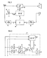
- Fig. 1 ein Blockschaltbild der Schaltungsanordnung,
- Fig. 2 ein Blockschaltbild einer Ähnlichkeits-Vergleichsschaltung . der Schaltungsanordnung in Fig. 1,
- Fig. 3 jeweils ein Blockschaltbild eines Stellgrößengenerators der
- und 4 Schaltungsanordnung in Fig. 1 gemäß einem ersten und zweiten Ausführungsbeispiel,
- Fig. 5 jeweils ein Blockschaltbild einer Wichtungsvorrichtung der
- und 6 Schaltungsanordnung in Fig. 1 gemäß einem ersten und zweiten Ausführungsbeispiel.
- 1 is a block diagram of the circuit arrangement,
- Fig. 2 is a block diagram of a similarity comparison circuit. the circuit arrangement in Fig. 1,
- Fig. 3 is a block diagram of a manipulated variable generator
- and 4 circuit arrangement in Fig. 1 according to a first and second embodiment,
- 5 each shows a block diagram of a weighting device of the
- and 6 circuit arrangement in Fig. 1 according to a first and second embodiment.
Bei dem mittels der Schaltungsanordnung in Fig. 1 realisierbaren Verfahren zum Anpassen der Lautstärke eines Lautsprechers (10) eines Autoradios an einen am Lautsprecherort, d. h. im Kraftfahrzeuginnenraum, herrschenden Störgeräuschpegel wird ein Mikrofon (11) verwendet, das das vom Lautsprecher abgestrahlte akustische Lautsprecherausgangssignal, mitunter auch Nutzsignal genannt, und das im Kraftfahrzeuginnenraum herrschende Störgeräusch gleichzeitig erfaßt. Aus dem elektrischen Mikrofonausgangssignal wird eine Stellgröße (z) für einen üblicherweise im Autoradio enthaltenen Regelverstärker (12) generiert und entsprechend das dem Lautsprecher zugeführte elektrische Nutzsignal UNutz in Abhängigkeit von dem Störgeräusch verstärkt.In the method that can be implemented by means of the circuit arrangement in FIG. 1 for adapting the volume of a loudspeaker (10) of a car radio to an interference noise level prevailing at the loudspeaker location, ie in the motor vehicle interior, a microphone (11) is used, which sometimes emits the acoustic loudspeaker output signal emitted by the loudspeaker also called useful signal, and simultaneously detects the interference noise prevailing in the motor vehicle interior. The electrical microphone output signal is used to generate a manipulated variable (z) for one usually contained in the car radio Control amplifier (12) generates and amplifies the electrical useful signal U Nutz supplied to the loudspeaker as a function of the noise.
Zur Gewinnung der Stellgröße (z) für den Regelverstärker (12) werden die Hüllkurven von.elektrischem Nutzsignal UNutz und elektrischem Mikrofonausgangssignal fortlaufend auf Ähnlichkeit geprüft und ein dem Ähnlichkeitsgrad proportionales Ähnlichkeitssignal (x) erzeugt. Das Ähnlichkeitssignal ist um so größer, je ähnlicher sich die beiden Hüllkurven sind. Die Hüllkurven sind sich wiederum desto ähnlicher, je geringer der Störgeräuschpegel ist. Das Ähnlichkeitssignal (x) wird nach einer ersten Methode, wie sie schaltungsmäßig in Fig. 3 dargestellt ist, mit einem vorgegebenen Sollwert USoll verglichen, der vorzugsweise in Abhängigkeit von der vorgewählten Lautstärke vorgegeben wird. Die Lautstärke wird wiederum mittels eines als Sollwertgeber (28) ausgebildeten manuellen Lautstärkestellers (13) von dem Bedienenden auf den gewünschten Wert eingestellt. Die Differenz zwischen Ähnlichkeitssignal und Sollwert wird integriert und bildet die dem Regelverstärker (12) über seinen Steuereingang (14) zugeführte Stellgröße (z). Entsprechend dieser Stellgröße (2) wird die manuell voreingestellte Lautstärke verändert. Nach einer zweiten Methode, wie sie mit der in Fig. 4 dargestellten Schaltung durchgeführt werden kann, wird der Variationsbereich des Ähnlichkeitssignals (
Das vorstehend beschriebene Verfahren läßt sich sowohl digital und unter Verwendung eines Mikroprozessors als auch analog realisieren. In den Ausführungsbeispielen gemäß Fig. 1 - 6 ist zur Durchführung des Verfahrens eine analoge Schaltungsanordnung gewählt.The method described above can be implemented digitally and using a microprocessor as well as analog. In the exemplary embodiments according to FIGS. 1-6, an analog circuit arrangement is selected for carrying out the method.
Bei dieser Schaltungsandordnung ist - ebenso wie bei einer digitalen Variante - das an dem Eingang des Regelverstärkers (12) gelegte elektrische Nutzsignal UNutz einem ersten Hüllkurvendetektor (15) und das elektrische Mikrofonausgangssignal einem zweiten Hüllkurvendetektor (16) einer Regelvorrichtung (36) zugeführt. Die beiden Hüllkurvendetektoren (15, 16) sind mit einer Vergleichsschaltung (17) verbunden, die die beiden Hüllkurven von Nutzsignal und Mikrofonausgangssignal auf Ähnlichkeit vergleicht und an ihrem Ausgang ein Ähnlichkeitssignal erzeugt. Der Vergleichsschaltung (17) ist ein Stellgrößengenerator (18 bzw. 18') nachgeschaltet, dessen Ausgang mit dem Steuereingang (14) des Regelverstärkers (12) verbunden ist.In this circuit arrangement, just as in a digital variant, the electrical useful signal U Nutz applied to the input of the control amplifier (12) is fed to a first envelope detector (15) and the electrical microphone output signal to a second envelope detector (16) of a control device (36). The two envelope detectors (15, 16) are connected to a comparison circuit (17) which compares the two envelopes of the useful signal and the microphone output signal for similarity and generates a similarity signal at their output. The comparison circuit (17) is followed by a manipulated variable generator (18 or 18 '), the output of which is connected to the control input (14) of the control amplifier (12).
Eine Ausführungsform der Vergleichsschaltung (17) ist in Fig. 2 im Blockschaltbild dargestellt. Jedem Hüllkurvendetektor (15, 16) ist über die Eingänge a und b der Vergleichsschaltung (17) die Reihenschaltung aus einem Differenzierer (19 bzw. 20) und einem Nullspannungskomparator (21 bzw. 22) nachgeschaltet. Die Ausgänge der beiden Nullspannungskomparatoren (21, 22) sind mit einem.Koinzidenzglied (23), hier einem Äquivalenz-Gatter, verbunden, an dessen Ausgang der Steuereingang eines Umschalters (24) angeschlossen ist. Je nach Ausgangssignal des Koinzidenzgliedes (23) legt der Umschalter (24) einen als Tiefpaß (25) ausgebildeten Mittelwertbildner an einen positiven bzw. negativen Spannungswert U , so daß am Ausgang des Umx schalters jeweils ein oberer und ein unterer Ausgabewert abnehmbar ist.An embodiment of the comparison circuit (17) is shown in Fig. 2 in the block diagram. Each envelope detector (15, 16) is followed by the series connection of a differentiator (19 or 20) and a zero voltage comparator (21 or 22) via the inputs a and b of the comparison circuit (17). The outputs of the two zero voltage comparators (21, 22) are connected to a coincidence element (23), here an equivalence gate, to the output of which the control input of a changeover switch (24) is connected. Depending on the output signal of the coincidence element (23), the changeover switch (24) places an averager formed as a low pass (25) on a positive or negative voltage value U, so that an upper and a lower output value can be removed at the output of the Umx switch.
Die Differenzierer (19, 20) erfassen die Änderungen in den Hüllkurvensignalen. Ist die Änderung, also die Steigung der Hüllkurve, positiv, so steht am Ausgang des zugeordneten Nullspannungskomparators (21 bzw. 22) ein logisch "1"-Signal an, ist die Steigung negativ, ein logisch "0"-Signal. Bei Koinzidenz der Vorzeichen der Steigungen der beiden Hüllkurven erscheint am Ausgang des Koinzidenzgliedes (23) ein logisch "1"-Signal und der Umschalter (24) nimmt die in Fig. 2 dargestellte Stellung ein. Im anderen Fall, also bei verschiedenen Vorzeichen der Steigungen, tritt am Ausgang des Koinzidenzgliedes (23) ein logisch "0"-Signal auf und der Umschalter (24) verbindet den Tiefpaß (25) mit dem Spannungswert -U . Am Ausgang des Tiefpasses (25) ist der zeitliche Mittelwert der entsprechend den Vorzeichen der Steigungen der Hüllkurve angelegten Spannungsbeträge +U x und -Ux als Ähnlichkeitssignal (
Bei einer digitalen Schaltungsanordnung wäre es zweckmäßig, die an den Eingängen (a und b) der Vergleichsschaltung auftretenden Hüllkurvensignale digital abzutasten und die einzelnen Abtastwerte digital miteinander zu vergleichen.In a digital circuit arrangement, it would be expedient to digitally sample the envelope signals occurring at the inputs (a and b) of the comparison circuit and to digitally compare the individual samples with one another.
Das Ähnlichkeitssignal (x) wird dem Stellgrößengenerator (18 bzw. 18') zugeführt, der aus dem Ähnlichkeitssignal (
In dem Ausführungsbeispiel gemäß Fig. 3 weist der Stellgrößengenerator (18) einen Subtrahierer (26) und einen diesem nachgeschalteten Integrierer (27) auf. An dem einen Eingang des Subtrahierers (26) liegt das Ähnlichkeitssignal (X) und an dem anderen Eingang eine vom Sollwertgeber (28) vorgegebene Stellspannung USoll. Die Differenzspannung am Ausgang des Subtrahierers (26) wird im Integrierer (27) integriert und als Stellgröße (z) unmittelbar dem Steuereingang (14) des Regelverstärkers (12) zugeführt.In the exemplary embodiment according to FIG. 3, the manipulated variable generator (18) has a subtractor (26) and an integrator (27) connected downstream of it. The similarity signal (X) is present at one input of the subtractor (26) and at the other input there is an actuating voltage U set specified by the setpoint generator (28). The differential voltage at the output of the subtractor (26) is integrated in the integrator (27) and fed directly to the control input (14) of the control amplifier (12) as a manipulated variable (z).
In dem Ausführungsbeispiel gemäß Fig. 4 weist der Stellgrößengenerator (18') eine Vielzahl von Schwellwertschaltern (40) und eine gleiche Anzahl von schaltbaren Dämpfungsgliedern (41) auf. Im gewählten Ausführungsbeispiel sind die Dämpfungsglieder in Reihe geschaltet. Die Reihenschaltung der Dämpfungsglieder (41) ist zwischen dem mit dem Sollwertgeber (28) verbundenen Eingang und dem Ausgang des Stellgrößengenerators (18') angeschlossen. Jedes Dämpfungsglied ist mittels eines zugeordneten Schwellwertschalters (40) zu- und abschaltbar, was durch den Dämpfungsgliedern (41) parallel geschalteten Ein-/Ausschaltern (42) symbolisch dargestellt ist. Jeder Schwellwertschalter (40) weist zur Erzeugung einer Schalthysterese eine obere Schaltschwelle und eine untere Schaltschwelle auf. Bei Überschreiten der oberen Schaltschwelle wird der jeweils zugeordnete Schalter (42) geöffnet, damit das zugeordnete Dämpfungsglied (41) zugeschaltet und die Stellgröße (z) um einen Schritt reduziert. Bei Unterschreiten der unteren Schaltschwelle wird der zugeordnete Schalter (42) geschlossen, damit das zugeordnete Dämpfungsglied (41) überbrückt, also abgeschaltet, und die Stellgröße (z) um einen Schritt erhebt. Die Schaltschwellen der Schwellwertschalter (40) sind gegeneinander so abgestuft, daß sich ein dem subjektiven Lautstärkeempfinden des menschlichen Ohrs optimal angepaßtes Regelverhalten ergibt. Nimmt das Ähnlichkeitssignal (i) seinen größten Wert Ux an (was bedeutet, daß Mikrofonausgangssignal und Nutzsignal identisch sind, also kein Störgeräusch vorhanden ist), so sind alle Schalter (42) geöffnet. Die dem Regelverstärker (12) zugeführte Stellgröße (z) ist minimal und ausschließlich von der Einstellung des Lautstärkestellers (13) abhängig. Sobald ein Störgeräusch auftritt, die Hüllkurvensignale sich weniger ähn-lich sind, nimmt der Wert des Ähnlichkeitssignals (x) ab. Sobald die untere Schaltschwelle des ersten Schwellwertschalters (40) unterschritten wird, wird der zugeordnete Schalter (42) geschlossen und damit die Stellgröße (z) um einen Schritt erhöht. Bei Unterschreiten der nächsten unteren Schaltschwelle spricht der nächste Schwellwertschalter (40) an und die Stellspannung USoll wird um einen weiteren, z. B. gleichen Betrag erhöht und so fort. Sind die Hüllkurvensignale extrem unähnlich, so weist das Ähnlichkeitssignal (
Der vorstehend beschriebene Regelmechanismus nutzt die Dynamik der Signale aus. Da aber auch in der Praxis Rauschsignale ohne wesentliche Dynamik vorkommen und störend wirken, werden zur Erfassung solcher Rauschsignale die am Ausgang des Umschalters (24) anstehenden Ausgabewerte +U x und -Ux gewichtet. Hierzu werden von den an den Eingängen a und b der Vergleichsschaltung (17) anstehenden Hüllkurvensignale von Nutzsignal einerseits und Mikrofonausgangssignal andererseits jeweils der Mittelwert und der Dynamikbereich bestimmt. Aus diesen Mittelwerten und Dynamikbereichen wird ein Dynamik- oder Wichtungsfaktor gewonnen, der zur Wichtung dieser Ausgabewerte dient. Gemäß einer ersten Verfahrensvariante wird dabei der Dynamikfaktor als Quotient der beiden Hüllkurvenverhältnisse der Hüllkurvensignale berechnet. Unter Hüllkurvenverhältnisse wird hierbei der Quotient des Mittelwertes zu dem Dynamikbereich eines Hüllkurvensignals verstanden.The control mechanism described above takes advantage of the dynamics of the signals. However, since noise signals also occur in practice without substantial dynamics and have a disturbing effect, the output values + U x and -U x present at the output of the changeover switch (24) are weighted for detecting such noise signals. For this purpose, the mean value and the dynamic range are determined from the envelope signals of the useful signal on the one hand and the microphone output signal on the other hand at the inputs a and b of the comparison circuit (17). A dynamic or weighting factor is obtained from these mean values and dynamic ranges, which is used to weight these output values. According to a first method variant, the dynamic factor is calculated as the quotient of the two envelope curve ratios of the envelope curve signals. Envelope ratios are understood to mean the quotient of the mean value to the dynamic range of an envelope signal.
Nach einer zweiten Verfahrensvariante, das wesentlich bessere Ergebnisse liefert, wird der Dynamikfaktor als Differenz aus dem Mittelwert des aus dem Mikrofonausgangssignal abgeleiteten Hüllkurvensignals und dem mit dem Mittelwert des Nutzsignal-Hüllkurvensignals multiplizierten Verhältnis der Dynamikbereiche der aus dem Mikrofonausgangssignal und aus dem Nutzsignal abgeleiteten Hüllkurvensignale gebildet. Die Wichtung erfolgt dann derart, daß der größere Ausgabewert um den Dynamikfaktor verkleinert und der kleinere Ausgabewert um den Dynamikfaktor vergrößert wird.According to a second variant of the method, which provides significantly better results, the dynamic factor is the difference between the mean value of the envelope signal derived from the microphone output signal and the ratio of the dynamic ranges of the microphone output signal and the useful signal multiplied by the mean value of the useful signal envelope signal derived envelope signals formed. The weighting is then carried out in such a way that the larger output value is reduced by the dynamic factor and the smaller output value is increased by the dynamic factor.
Zur Wichtung der Ausgabewerte +Ux und -Ux weist die Vergleichsschaltung (17) eine Wichtungsvorrichtung (29 oder 29') auf, die im einzelnen in Fig. 5 bzw. 6 dargestellt ist. Bei beiden Wichtungsvorrichtungen (29 und 29') sind die an die Hüllkurvendetektoren (15, 16) angeschlossenen Eingänge a und b der Vergleichsschaltung (17) jeweils mit einem als Tiefpaß (30 bzw. 31) ausgebildeten Mittelwertbildner und einem Dynamikdetektor (32 bzw. 33) verbunden. Die Dynamikdetektoren (32, 33) sind Umformer zur Umwandlung des Spitze-Spitze-Wertes der Hüllkurvensignale in eine Gleichspannung. Ein solcher Umformer kann aus zwei Spitzenwertdetektoren und einem Subtrahierer bestehen, wobei jeweils ein Spitzenwertdetekor den oberen bzw. unteren Spitzenwert des Hüllkurvensignals erfaßt. Die Ausgänge der insgesamt zwei Tiefpässe (30, 31) und der beiden Dynamikdetektoren (32, 33) sind mit einem Rechenwerk (34 bzw. 34') verbunden. Am Ausgang des Rechenwerkes (34 bzw. 34') ist ein Gleichspannungswert U5 bzw. U5, abnehmbar, der unmittelbar als gewichteter Spannungswert +Ux an dem Eingang des Umschalters (24) und über einen Negierer (35 bzw. 35') als gewichteter Spannungswert -U x am anderen Eingang des Umschalters (24) anliegt.In order to weight the output values + U x and -U x , the comparison circuit (17) has a weighting device (29 or 29 '), which is shown in detail in FIGS. 5 and 6, respectively. In both weighting devices (29 and 29 '), the inputs a and b of the comparison circuit (17) connected to the envelope detectors (15, 16) each have an averager designed as a low-pass filter (30 or 31) and a dynamic detector (32 or 33 ) connected. The dynamic detectors (32, 33) are converters for converting the peak-to-peak value of the envelope signals into a DC voltage. Such a converter can consist of two peak value detectors and a subtractor, a peak value detector in each case detecting the upper and lower peak value of the envelope signal. The outputs of the two low-pass filters (30, 31) and the two dynamic detectors (32, 33) are connected to an arithmetic unit (34 and 34 '). At the output of the arithmetic unit (34 or 34 '), a DC voltage value U 5 or U 5 can be removed, which is directly as a weighted voltage value + U x at the input of the switch (24) and via a negator (35 or 35') is present as a weighted voltage value -U x at the other input of the switch (24).
Das Rechenwerk (34) in Fig. 5 bildet aus den Ausgangsspannungen U1 bis U4 der Mittelwertbildner (30, 31) und der Dynamikdetektoren (32, 33) und einer Referenzgleichspannung Uref' die Gleichspannung U5 gemäß
Der Dynamikfaktor a gemäß
Das Rechenwerk (34') in der Wichtungsvorrichtung (29') in Fig. 6 bildet aus den Eingangsspannungen U1 bis U4 der Tiefpässe (30, 31) und der Dynamikdetektoren (32, 33) und der Referenzgleichspannung Uref, die dem Maximalwert des Mikrofonsignals entspricht, die Spannung U'S gemäß
Hierzu weist das Rechenwerk (34') einen Dividierer (43), einen Multiplizierer (44) und einen Addierer (45) auf, die in der in Fig. 6 dargestellten Weise miteinander und mit den Ausgängen der Tiefpässe (30, 31) und der Dynamikdetektoren (32, 33) verbunden sind. Zwischen dem Eingang des Addierers (45) und dem Ausgang des Tiefpasses (31) ist noch ein Inverter (46) eingeschaltet. Die Spannung U'S ist wiederum als gewichteter Spannungswert +Ux bzw. -Ux dem Umschalter (24) zugeführt. Der Dynamikfaktor b gemäß

Wie nicht weiter dargestellt, aber per Software oder Hardware ohne weiteres realisierbar, wird der Ähnlichkeitsvergleich der Hüllkurven von elektrischem Nutzsignal UNutz und elektrischem Mikrofonausgangssignal nur außerhalb von Signalpausen im Nutzsignal durchgeführt. Hierzu werden im Nutzsignal die Signalpausen detektiert und während dieser Signalpausen der Ähnlichkeitsvergleich unterbunden. Dadurch wird verhindert, daß in Signalpausen das Ähnlichkeitssignal bei anwesendem Störgeräusch sehr klein wird und damit unzulässigerweise zu einer großen Stellgröße führt. Außerdem kann zur Unterbindung des Einflusses der kurzzeitigen Dynamik der Nutz- und Störgeräuschsignale eine Lautstärkeanpassung und damit eine Veränderung der Stellgröße (z) nur dann vorgenommen werden, wenn sich der Wert der Stellgröße (z) außerhalb eines vorgegebenen Toleranzfensters befindet. Bei dem Stellgrößengenerator (18) gemäß Fig. 3 ist dieses Toleranzfenster um den Sollwert USoll gelegt. Die Erfindung ist nicht auf das vorstehend beschriebene Ausführungsbeispiel der analogen Schaltungsanordnung beschränkt. So kann das erfindungsgemäße Verfahren digital realisiert werden. In diesem Fall sind die Spannungswerte +Ux und -U x digitale Werte mit vorgegebener Größe bzw. Null, deren in einer ALU berechneter Mittelwert das digitale Ähnlichkeitssignal (x) bildet. Das Verfahren funktioniert in gleicher Weise und auch die Wirkungsweise der digitalen Vorrichtung ist wie vorstehend beschrieben, unter Berücksichtigung der durch die Digitaltechnik geforderten Besonderheiten.As not shown further, but can be easily implemented by software or hardware, the similarity comparison of the envelopes of the electrical useful signal U Nutz and the electrical microphone output signal is only carried out outside of signal pauses in the useful signal. For this purpose, the signal pauses are detected in the useful signal and the similarity comparison is prevented during these signal pauses. This prevents the similarity signal from becoming very small in the case of pauses in the presence of background noise and thus inadmissibly leading to a large manipulated variable. In addition, in order to prevent the influence of the short-term dynamics of the useful and noise signals, the volume can be adjusted and the manipulated variable (z) can only be changed if the value of the manipulated variable (z) is outside a specified tolerance window. In the manipulated variable generator (18) according to FIG. 3, this tolerance window is placed around the target value U target . The invention is not restricted to the exemplary embodiment of the analog circuit arrangement described above. The method according to the invention can thus be implemented digitally. In this case, the voltage values + U x and -U x are digital values with a predetermined size or zero, the mean value of which is calculated in an ALU and forms the digital similarity signal (x). The method works in the same way and the mode of operation of the digital device is as described above, taking into account the special features required by digital technology.
Anstelle des Koinzidenzgliedes (23) in Fig. 2 kann auch ein Exklusiv-Oder-Gatter zusammen mit dem Umschalter (24) eine Koinzidenzschaltung bilden. In diesem Fall sind bei gleicher Stellung des Umschalters (24) die Ausgangssignale des Exklusiv-Oder-Gatters gegenüber denen des Koinzidenzgliedes (23) vertauscht.Instead of the coincidence element (23) in FIG. 2, an exclusive-OR gate can also form a coincidence circuit together with the changeover switch (24). In this case, the output signals of the exclusive-OR gate are interchanged with those of the coincidence element (23) when the switch (24) is in the same position.
Claims (10)
daß die Hüllkurven von Nutzsignal und Mikrofonausgangssignal fortlaufend auf Ähnlichkeit geprüft werden, daß ein dem Ähnlichkeitsgrad proportionales Ähnlichkeitssignal erzeugt wird, und daß die Stellgröße aus dem Ähnlichkeitssignal abgeleitet wird.1. A method for adjusting the volume of a loudspeaker, in particular in a mobile radio receiver, such as a car radio or the like, to a noise level prevailing at the loudspeaker location using a controllable control amplifier for amplifying a useful signal for the loudspeaker and a microphone for detecting a composite of loudspeaker output signal and noise acoustic signal, in which a manipulated variable for the control amplifier is generated by means of the electrical microphone output signal, characterized in that
that the envelopes of the useful signal and the microphone output signal are continuously checked for similarity, that a similarity signal proportional to the degree of similarity is generated, and that the manipulated variable is derived from the similarity signal.
dadurch gekennzeichnet,
daß zur Ableitung der Stellgröße aus dem Ähnlichkeitssignal dieses mit einem vorzugsweise in Abhängigkeit von der vorgewählten Lautstärke vorgegebenen Sollwert verglichen, und daß durch Integration der Differenzwerte zwischen Ähnlichkeitssignal und Sollwert die Stellgröße bestimmt wird.2. The method according to claim 1,
characterized,
that in order to derive the manipulated variable from the similarity signal, this is compared with a desired value, which is preferably predetermined as a function of the preselected volume, and that the manipulated variable is determined by integrating the difference values between the similarity signal and the desired value.
dadurch gekennzeichnet,
daß zur Ableitung der Stellgröße aus dem Ähnlichkeitssignal mindestens ein Teil des Variationsbereichs des Ähnlichkeitssignals durch Schwellwertstufen unterteilt wird, und daß bei Durchlaufen der Schwellwertstufen durch das Ähnlichkeitssignal eine vorgewählte Lautstärke je nach Durchlaufrichtung um je einen Schritt erhöht oder reduziert wird, wobei den Schwellwertstufen jeweils eine obere und eine untere Schaltschwelle zugeordnet werden, und daß die Stellgröße bei Unterschreiten der unteren Schaltschwelle erhöht und bei Überschreiten der oberen Schaltschwelle reduziert wird.3. The method according to claim 1,
characterized,
that in order to derive the manipulated variable from the similarity signal, at least part of the variation range of the similarity signal is divided by threshold value levels, and that when the threshold value levels are passed through the similarity signal, a preselected volume is increased or decreased by one step depending on the direction of flow, with the threshold value levels each having an upper level and a lower switching threshold are assigned, and that the manipulated variable is increased when the lower switching threshold is undershot and reduced when the upper switching threshold is exceeded.
dacurch gekennzeichnet,
daß zur Ähnlichkeitsprüfung die Vorzeichen der Steigungen der Hüllkurven fortlaufend bestimmt werden, daß die Vorzeichen verglichen werden und bei Gleichheit ein vorgegebener erster Wert und bei Ungleichheit ein davon abweichender vorgegebener zweiter Wert ausgegeben wird, und daß das Ähnlichkeitssignal als Mittelwert der Ausgabewerte bestimmt wird, und daß vorzugsweise der erste Ausgabewert größer ist als der zweite Ausgabewert.4. The method according to any one of claims 1-3,
characterized by
that the signs of the slopes of the envelopes are continuously determined for the similarity test, that the signs are compared and a predetermined first value is output in the case of equality and a predetermined second value which is different in the case of inequality, and that the similarity signal is determined as the mean value of the output values, and preferably the first output value is greater than the second output value.
dadurch gekennzeichnet,
daß aus dem Nutzsignal und aus dem Mikrofonausgangssignal jeweils ein Hüllkurvensignal abgeleitet wird, daß der Mittelwert und der Dynamikbereich von jedem Hüllkurvensignal bestimmt werden und daraus ein Dynamikfaktor gewonnen wird, und daß die Ausgabewerte mit dem Dynamikfaktor gewichtet werden.5. The method according to claim 4,
characterized,
that an envelope signal is derived from the useful signal and from the microphone output signal, that the mean value and the dynamic range of each envelope signal are determined and a dynamic factor is obtained therefrom, and that the output values are weighted with the dynamic factor.
dadurch gekennzeichnet,
daß der Dynamikfaktor als Differenz aus dem Mittelwert des aus dem Mikrofonausgangssignal abgeleiteten HüJ.lkurvensignals und dem mit dem Mittelwert des Nutzsignal-hüllkurvensignals multiplizierten Verhältnisses der Dynamikbereiche der aus dem Mikrofonausgangssignal und aus dem Nutzsignal abgeleiteten Hüllkurvensignale gebildet wird, wobei die Wichtung derart erfolgt, daß der größere Ausgabewert um den Dynamikfaktor verkleinert und der kleinere Ausgabewert um den Dynamikfaktor vergrößert wird.6. The method according to claim 5,
characterized,
that the dynamic factor is formed as the difference between the mean value of the envelope signal derived from the microphone output signal and the ratio of the dynamic ranges of the envelope signals derived from the microphone output signal and the useful signal multiplied by the mean value of the useful signal envelope signal, the weighting being such that the the larger output value is reduced by the dynamic factor and the smaller output value is increased by the dynamic factor.
dadurch gekennzeichnet,
daß Signalpausen im Nutzsignal detektiert werden, und daß während der Signalpausen ein Ähnlichkeitsvergleich der Hüllkurven unterbunden wird.7. The method according to any one of claims 1-6,
characterized,
that signal pauses in the useful signal are detected and that a similarity comparison of the envelopes is prevented during the signal pauses.
dadurch gekennzeichnet,
daß die Regelvorrichtung (36) zwei Hüllkurvendetektoren (15, 16) aufweist, von denen der eine mit seinem Eingang an dem Eingang des Regelverstärkers (12) und der andere mit seinem Eingang an dem Mikrofonausgang angeschlossen ist, daß mit den Ausgängen der Hüllkurvendetektoren (15, 16) die beiden Eingänge (a, b) einer Vergleichsschaltung (17) verbunden sind, die ein für die Ähnlichkeit der Hüllkurven von Nutzsignal und Mikrofonausgangssignal charakteristisches Ähnlichkeitssignal (X) erzeugt, und daß der Vergleichsschaltung (17) ein Stellgrößengenerator (18, 18') nachgeschaltet ist, dessen Ausgang mit dem Steuereingang (14) des Regelverstärkers (12) verbunden ist.8. Circuit arrangement for carrying out the method according to one of claims 1-7 with a control amplifier connected upstream of the loudspeaker with a manual volume control acting thereon, with a microphone for recording an acoustic signal composed of loudspeaker output signal and noise and with a control device for generating a manipulated variable proportional to noise Control amplifier,
characterized,
that the control device (36) has two envelope detectors (15, 16), one of which is connected with its input to the input of the control amplifier (12) and the other with its input to the microphone output, that with the outputs of the envelope detector (15 , 16) the two inputs (a, b) are connected to a comparison circuit (17) which generates a similarity signal (X) which is characteristic of the similarity of the envelopes of the useful signal and the microphone output signal, and that the comparison circuit (17) has a manipulated variable generator (18, 18 ') is connected downstream, the output of which is connected to the control input (14) of the control amplifier (12).
dadurch gekennzeichnet,
daß der Stellgrößengenerator (18) einen Subtrahierer (26) und einen diesem nachgeschalteten Integrierer (27) aufweist, und daß der eine Eingang des Subtrahierers (26) mit dem Ähnlichkeitssignal (x) und der andere Eingang des Subtrahierers (26) mit einem vorzugsweise von der Einstellung des Lautstärkestellers (13) abhängigen Sollwert (USoll) belegt ist.9. Circuit arrangement according to claim 8,
characterized,
that the manipulated variable generator (18) has a subtractor (26) and an integrator (27) connected downstream thereof, and that one input of the subtractor (26) with the similarity signal (x) and the other input of the subtractor (26) with a preferably of the Setting of the volume control (13) dependent setpoint (U set ) is occupied.
dadurch gekennzeichnet,
daß die Vergleichsschaltung (17) zwei jeweils das Vorzeichen der Hüllkurvensteigungen erfassende Detektoren (19, 21 bzw. 20, 22), eine mit den Detektoren (19, 21 bzw. 20, 22) verbundene Koinzidenzschaltung (23, 24), die bei Vorzeichen-Übereinstimmung einen vorgegebenen ersten Wert (+U ) und bei Nichtübereinstimmung der Vorzeichen einen vorgegebenen x zweiten Wert (-U ) ausgibt und einen der Koinzidenzschaltung (23, 24) x nachgeschalteten Mittelwertbildner (25) aufweist, dessen das Ähnlicbkeitssignal (
characterized,
that the comparison circuit (17) has two detectors (19, 21 and 20, 22), each of which detects the sign of the envelope slope, a coincidence circuit (23, 24) connected to the detectors (19, 21 and 20, 22), respectively, which has a sign -Accordance outputs a predefined first value (+ U) and, if the signs do not match, a predefined x second value (-U) and one of the coincidence circuits (23, 24) x has an averager (25), the similarity signal (
Priority Applications (1)
| Application Number | Priority Date | Filing Date | Title |
|---|---|---|---|
| AT84110248T ATE42655T1 (en) | 1983-09-22 | 1984-08-29 | METHOD OF ADJUSTING THE VOLUME OF A SPEAKER TO A NOISE LEVEL PRESENT AT THE SPEAKER LOCATION. |
Applications Claiming Priority (2)
| Application Number | Priority Date | Filing Date | Title |
|---|---|---|---|
| DE3334262 | 1983-09-22 | ||
| DE3334262 | 1983-09-22 |
Publications (3)
| Publication Number | Publication Date |
|---|---|
| EP0141129A2 true EP0141129A2 (en) | 1985-05-15 |
| EP0141129A3 EP0141129A3 (en) | 1985-10-16 |
| EP0141129B1 EP0141129B1 (en) | 1989-04-26 |
Family
ID=6209770
Family Applications (1)
| Application Number | Title | Priority Date | Filing Date |
|---|---|---|---|
| EP84110248A Expired EP0141129B1 (en) | 1983-09-22 | 1984-08-29 | Method of adapting the sound volume of a loudspeaker in accordance with the ambiant noise level |
Country Status (4)
| Country | Link |
|---|---|
| EP (1) | EP0141129B1 (en) |
| JP (1) | JPS60106216A (en) |
| AT (1) | ATE42655T1 (en) |
| DE (1) | DE3477982D1 (en) |
Cited By (3)
| Publication number | Priority date | Publication date | Assignee | Title |
|---|---|---|---|---|
| EP0641070A1 (en) * | 1993-08-27 | 1995-03-01 | Blaupunkt-Werke GmbH | Method and circuit for the adjustment of the level of sound sources in accordance with the ambient noise level |
| WO2002089452A1 (en) | 2001-04-26 | 2002-11-07 | Harman/Becker Automotive Systems (Straubing Division) Gmbh | Circuit for audio playback and for hands-free operation in a motor vehicle |
| US6529605B1 (en) | 2000-04-14 | 2003-03-04 | Harman International Industries, Incorporated | Method and apparatus for dynamic sound optimization |
Families Citing this family (1)
| Publication number | Priority date | Publication date | Assignee | Title |
|---|---|---|---|---|
| US5766344A (en) | 1991-09-21 | 1998-06-16 | Semiconductor Energy Laboratory Co., Ltd. | Method for forming a semiconductor |
Family Cites Families (1)
| Publication number | Priority date | Publication date | Assignee | Title |
|---|---|---|---|---|
| JPS55147014A (en) * | 1979-05-07 | 1980-11-15 | Hitachi Ltd | Automatic adjusting unit for sound volume and sound quality |
-
1984
- 1984-08-29 DE DE8484110248T patent/DE3477982D1/en not_active Expired
- 1984-08-29 AT AT84110248T patent/ATE42655T1/en not_active IP Right Cessation
- 1984-08-29 EP EP84110248A patent/EP0141129B1/en not_active Expired
- 1984-09-17 JP JP59192779A patent/JPS60106216A/en active Pending
Non-Patent Citations (3)
| Title |
|---|
| ELECTRICAL DESIGN NEWS, Band 26, Nr. 1, 7. Januar 1981, Seite 202, Boston, Massachusetts, US; J. GRAEME: "Feedback lowers AGC distortion" * |
| RADIO FERNSEHEN ELEKTRONIK, Band 29, Nr. 8, August 1980, Seite 539, Berlin, DE; "Störgeräuschabhängige automatische Lautstärkesteuerung" * |
| TECHNISCHE MITTEILUNGEN AEG-TELEFUNKEN, Band 61, Nr. 3, 1971, Seiten 186-189; A. HÄFNER: "Geräuschabhängige elektronische Lautstärkeeinstellung EL 100" * |
Cited By (3)
| Publication number | Priority date | Publication date | Assignee | Title |
|---|---|---|---|---|
| EP0641070A1 (en) * | 1993-08-27 | 1995-03-01 | Blaupunkt-Werke GmbH | Method and circuit for the adjustment of the level of sound sources in accordance with the ambient noise level |
| US6529605B1 (en) | 2000-04-14 | 2003-03-04 | Harman International Industries, Incorporated | Method and apparatus for dynamic sound optimization |
| WO2002089452A1 (en) | 2001-04-26 | 2002-11-07 | Harman/Becker Automotive Systems (Straubing Division) Gmbh | Circuit for audio playback and for hands-free operation in a motor vehicle |
Also Published As
| Publication number | Publication date |
|---|---|
| DE3477982D1 (en) | 1989-06-01 |
| JPS60106216A (en) | 1985-06-11 |
| EP0141129B1 (en) | 1989-04-26 |
| EP0141129A3 (en) | 1985-10-16 |
| ATE42655T1 (en) | 1989-05-15 |
Similar Documents
| Publication | Publication Date | Title |
|---|---|---|
| DE3426068C2 (en) | ||
| DE4038805C2 (en) | Device for automatically adjusting the volume | |
| EP1366564B1 (en) | Device for the noise-dependent adjustment of sound volumes | |
| EP0290952B1 (en) | Speech control circuitry for a telecommunication terminal | |
| DE69628411T2 (en) | Device and method for noise reduction of a speech signal | |
| DE19502047C2 (en) | Process for analog-digital conversion of signals | |
| DE4021969C2 (en) | Automatic volume control | |
| DE4017596A1 (en) | DEVICE FOR AUTOMATIC VOLUME CONTROL IN VEHICLES | |
| DE3315150A1 (en) | AUTOMATIC VOLUME CONTROL DEVICE | |
| DE3802903A1 (en) | LANGUAGE TRANSFER DEVICE | |
| CH644974A5 (en) | CIRCUIT ARRANGEMENT FOR AUTOMATICALLY ADJUSTING THE VOLUME AT LEAST ONE SPEAKER TO A NOISE LEVEL FOR RADIO RECEIVERS IN THE SPEAKER LOCATION. | |
| DE3525472C2 (en) | Arrangement for detecting pulse-like disturbances and arrangement for their suppression | |
| DE102009016845B3 (en) | Arrangement and method for detecting feedback in hearing devices | |
| EP1369994B1 (en) | Method for boosting low frequencies adapted to an auditory system and corresponding reproduction system | |
| DE2846234C3 (en) | Circuit arrangement for automatic gain control of a single sideband receiver | |
| EP0600164A1 (en) | Method for the improvement of transmission properties of an electro-acoustic device | |
| EP0141129B1 (en) | Method of adapting the sound volume of a loudspeaker in accordance with the ambiant noise level | |
| EP0027519A1 (en) | Circuit arrangement for the automatic volume control of a loudspeaker in dependence upon an interference noise level prevailing at the loudspeaker's location | |
| EP1458216B1 (en) | Device and method for adaption of microphones in a hearing aid | |
| EP0140333A2 (en) | Sound reproducing system | |
| DE2456468B2 (en) | Electroacoustic «sound reproduction device with an amplifier controlled by a noise detector | |
| EP0613295A1 (en) | Device for generating a noise detection signal | |
| DE3320751A1 (en) | Circuit arrangement for automatically adapting the volume of a loudspeaker to an interfering noise level prevailing at the loudspeaker location | |
| EP0592787A1 (en) | Procedure for improvement of acoustic feedback suppression of electro-acoustic devices | |
| DE69731455T2 (en) | INTERFERENCE DETECTION CIRCUIT WITH DISCRIMINATION BY AMPLITUDE FREQUENCY DOMAIN DEFINITION |
Legal Events
| Date | Code | Title | Description |
|---|---|---|---|
| PUAI | Public reference made under article 153(3) epc to a published international application that has entered the european phase |
Free format text: ORIGINAL CODE: 0009012 |
|
| AK | Designated contracting states |
Designated state(s): AT CH DE FR GB IT LI |
|
| PUAL | Search report despatched |
Free format text: ORIGINAL CODE: 0009013 |
|
| AK | Designated contracting states |
Designated state(s): AT CH DE FR GB IT LI |
|
| 17P | Request for examination filed |
Effective date: 19860318 |
|
| 17Q | First examination report despatched |
Effective date: 19870810 |
|
| GRAA | (expected) grant |
Free format text: ORIGINAL CODE: 0009210 |
|
| AK | Designated contracting states |
Kind code of ref document: B1 Designated state(s): AT CH DE FR GB IT LI |
|
| REF | Corresponds to: |
Ref document number: 42655 Country of ref document: AT Date of ref document: 19890515 Kind code of ref document: T |
|
| GBT | Gb: translation of ep patent filed (gb section 77(6)(a)/1977) | ||
| REF | Corresponds to: |
Ref document number: 3477982 Country of ref document: DE Date of ref document: 19890601 |
|
| ET | Fr: translation filed | ||
| ITF | It: translation for a ep patent filed |
Owner name: STUDIO JAUMANN |
|
| PLBE | No opposition filed within time limit |
Free format text: ORIGINAL CODE: 0009261 |
|
| STAA | Information on the status of an ep patent application or granted ep patent |
Free format text: STATUS: NO OPPOSITION FILED WITHIN TIME LIMIT |
|
| 26N | No opposition filed | ||
| ITTA | It: last paid annual fee | ||
| PGFP | Annual fee paid to national office [announced via postgrant information from national office to epo] |
Ref country code: GB Payment date: 19960809 Year of fee payment: 13 |
|
| PGFP | Annual fee paid to national office [announced via postgrant information from national office to epo] |
Ref country code: FR Payment date: 19960814 Year of fee payment: 13 |
|
| PGFP | Annual fee paid to national office [announced via postgrant information from national office to epo] |
Ref country code: AT Payment date: 19960820 Year of fee payment: 13 |
|
| PGFP | Annual fee paid to national office [announced via postgrant information from national office to epo] |
Ref country code: CH Payment date: 19960823 Year of fee payment: 13 |
|
| PGFP | Annual fee paid to national office [announced via postgrant information from national office to epo] |
Ref country code: DE Payment date: 19961024 Year of fee payment: 13 |
|
| PG25 | Lapsed in a contracting state [announced via postgrant information from national office to epo] |
Ref country code: GB Free format text: LAPSE BECAUSE OF NON-PAYMENT OF DUE FEES Effective date: 19970829 Ref country code: AT Free format text: LAPSE BECAUSE OF NON-PAYMENT OF DUE FEES Effective date: 19970829 |
|
| PG25 | Lapsed in a contracting state [announced via postgrant information from national office to epo] |
Ref country code: LI Free format text: LAPSE BECAUSE OF NON-PAYMENT OF DUE FEES Effective date: 19970831 Ref country code: CH Free format text: LAPSE BECAUSE OF NON-PAYMENT OF DUE FEES Effective date: 19970831 |
|
| REG | Reference to a national code |
Ref country code: CH Ref legal event code: PL |
|
| GBPC | Gb: european patent ceased through non-payment of renewal fee |
Effective date: 19970829 |
|
| PG25 | Lapsed in a contracting state [announced via postgrant information from national office to epo] |
Ref country code: FR Free format text: LAPSE BECAUSE OF NON-PAYMENT OF DUE FEES Effective date: 19980430 |
|
| PG25 | Lapsed in a contracting state [announced via postgrant information from national office to epo] |
Ref country code: DE Free format text: LAPSE BECAUSE OF NON-PAYMENT OF DUE FEES Effective date: 19980501 |
|
| REG | Reference to a national code |
Ref country code: FR Ref legal event code: ST |