EP0117832A2 - Vehicle multiplex system having protocol/format for secure communication transactions - Google Patents
Vehicle multiplex system having protocol/format for secure communication transactions Download PDFInfo
- Publication number
- EP0117832A2 EP0117832A2 EP84630013A EP84630013A EP0117832A2 EP 0117832 A2 EP0117832 A2 EP 0117832A2 EP 84630013 A EP84630013 A EP 84630013A EP 84630013 A EP84630013 A EP 84630013A EP 0117832 A2 EP0117832 A2 EP 0117832A2
- Authority
- EP
- European Patent Office
- Prior art keywords
- byte
- command
- master controller
- message
- controller
- Prior art date
- Legal status (The legal status is an assumption and is not a legal conclusion. Google has not performed a legal analysis and makes no representation as to the accuracy of the status listed.)
- Granted
Links
Images


Classifications
-
- H—ELECTRICITY
- H04—ELECTRIC COMMUNICATION TECHNIQUE
- H04Q—SELECTING
- H04Q9/00—Arrangements in telecontrol or telemetry systems for selectively calling a substation from a main station, in which substation desired apparatus is selected for applying a control signal thereto or for obtaining measured values therefrom
- H04Q9/14—Calling by using pulses
-
- G—PHYSICS
- G08—SIGNALLING
- G08C—TRANSMISSION SYSTEMS FOR MEASURED VALUES, CONTROL OR SIMILAR SIGNALS
- G08C25/00—Arrangements for preventing or correcting errors; Monitoring arrangements
-
- B—PERFORMING OPERATIONS; TRANSPORTING
- B60—VEHICLES IN GENERAL
- B60R—VEHICLES, VEHICLE FITTINGS, OR VEHICLE PARTS, NOT OTHERWISE PROVIDED FOR
- B60R16/00—Electric or fluid circuits specially adapted for vehicles and not otherwise provided for; Arrangement of elements of electric or fluid circuits specially adapted for vehicles and not otherwise provided for
- B60R16/02—Electric or fluid circuits specially adapted for vehicles and not otherwise provided for; Arrangement of elements of electric or fluid circuits specially adapted for vehicles and not otherwise provided for electric constitutive elements
- B60R16/03—Electric or fluid circuits specially adapted for vehicles and not otherwise provided for; Arrangement of elements of electric or fluid circuits specially adapted for vehicles and not otherwise provided for electric constitutive elements for supply of electrical power to vehicle subsystems or for
- B60R16/0315—Electric or fluid circuits specially adapted for vehicles and not otherwise provided for; Arrangement of elements of electric or fluid circuits specially adapted for vehicles and not otherwise provided for electric constitutive elements for supply of electrical power to vehicle subsystems or for using multiplexing techniques
Definitions
- the invention relates to an automotive vehicle electrical system and more particularly to a multiplex system for use in an automotive vehicle electrical system. More particularly still, the invention relates to a serial protocol/format for a multiplex system.
- a noise tolerant multiplex system having a transmitter and a receiver, and in which the transmitter includes a tri-state driver for generating a three-level serial data output signal indicative of the status of input switches.
- the data is generated at a high rate to eliminate any deleterious effects of noise on the system. Specifically, when an input switch is closed, the resulting serial data is transmitted to the receiver at a rate of 10,000 times per second, and the transmission continues as long as the input switch remains closed. Because of this high update rate, occasional incorrect data resulting from noise transients is replaced by correct control data, and the slow-responding loads, such as motors, respond in a correct manner.
- U.S. Patent 4,302,841 to McCulloch in which a microprocessor based transmitter utilizes a serial data line for transmitting data to a plurality of load-controlling receivers connected therealong.
- the transmitter responds to the states of a plurality of control switches to produce a sequence of digital messages, or words, each containing an address byte, or code, and a command byte, or code.
- Each receiver includes address code recognition means, and operates to control the associated loads in accordance with the command code included in the same word as its address code.
- the transmitter is such that each word of the digital sequence contains in addition to the address code and the command code, a repetition of one code and the inverse of the other code.
- Each receiver is capable of checking that each code is consistent with its repetition or inverse.
- Each receiver is also capable of sending a reply code to the transmitter signifying that the loads controlled by that receiver are appropriately energized.
- each word produced by the transmitter contains, in order, the address code, a repetition of the address code, the command code and the inverse of the command code.
- the receiver may refuse to receive the command code and its inverse unless it has received the appropriate address code twice. This system achieves a level of noise immunity since each receiver only receives command data when the address data has already been checked.
- the multiplex system of the aforementioned U.S. Patent 4,276,640 is intended for use in a single-receiver system and places reliance upon the relatively slow response rates of the loads and a relatively rapid, repeated data rate to minimixe the effects of noise. Such constraints may be unacceptable in a system requiring several receivers and/or a slower data rate. Moreover, it is unclear how the system responds when two or more input switches are closed concurrently.
- the system of the aforementioned U.S. Patent 4,302,841 provides for transmitting data to each of several receivers, and it formats the data in such a way that circuitry associated with the receiver may, under certain circumstances, determine that an incorrect signal has been received and close down the receiver.
- that system possesses certain characteristics which might be viewed as limitations in certain circumstances. For instance, without a reply address the transmitter does not know which receiver is responding; there is no provision for receiving switch inputs at the receivers; two-bit errors might go unnoticed; and the overhead for error checking is one hundred percent, with an error byte for each message byte.
- serial multiplex system having a master controller, a plurality of remote controllers and an improved serial data protocol/format between the controllers for improving the system's security against interference from electrical noise.
- Stringent error detection and rejection capabilities are provided in the communications protocol/format.
- protocol refers to the line discipline or set.of rules that are followed by interconnected devices on the bus in order to insure the orderly transfer of information
- format refers to the number of bits per transmission on the bus.
- the master controllers and remote controllers are structured to interact with a protocol/format which comprises successive transactions between the master controller and respective ones of the remote controllers.
- Each transaction is bidirectional and comprises a multibyte command message from the master controller to a particular remote controller, and a multibyte reply message in the reverse direction.
- the command message includes a particular address byte for a particular intended remote controller, and a command byte.
- the reply message includes the particular address byte of the particular answering remote controller, and a response byte indicative of a response to the command received by answering remote controller.
- the response may indicate the response of an output device to a command or it may reveal an input from an input device.
- the master controller includes the capability of verifying that the address byte received in the reply corresponds with that transmitted in the command message, and that the response byte received in the reply is indicative of the anticipated response to the command byte transmitted in the command message. Absent such verification, the master controller will at least once repeat transmission of the command message.
- each transaction includes an error check byte transmitted as part of the command message and an error check byte transmitted as part of the reply message. Failure of an error check match at the remote controller is reflected in the response byte of the reply message, and failure of an error check match at the master controller is determined there, either one of which events will result in the master controller at least once repeating the command message.
- a preferred error check is a cyclical redundancy check based on the address and command bytes in the command message, and based on the address and reply bytes in the reply message.
- a multibit sync byte is transmitted by the master controller to initiate each transaction and terminate a possible interval of latency.
- the sync byte and each byte of the transaction are eight bits in the illustrated embodiment.
- the multiplexer system includes a master controller 10 operatively connected to a plurality of remote controllers 12 individually numbered #1 through #n.
- the remote controllers 12 are each connected to a four-wire multiplex bus extending from the master controller 10.
- One conductor in bus 14, wire 16 provides a signal ground to which the master controller 10 and each of the remote controllers 12 are connected.
- Another conductor in bus 14, wire 18, conveys a +5V DC voltage level to the master controller 10 and each of the remote controllers 12 for powering the electronic circuitry of those controllers.
- the 5V DC supply is obtained from a 5V regulator 19 in turn connected to the 12V DC power system 20 of an automotive vehicle.
- a further conductor in bus 14, wire 22, conveys serial data between the master controller 10 and the several remote controllers 12 in accordance with the protocol/format of the present invention.
- a fourth conductor in bus 14, wire 24, conveys the multiplex clock signal from the master controller 10 to each of the remote controllers 12.
- each of the remote controllers 12 is utilized to receive one or more inputs from various respective vehicle switches and/or sensors, and/or to provide one or more outputs to various respective vehicle loads, thereby to serve the "body electrical" functions of the vehicle.
- a controller 12 may receive plural (i.e., 4-8) input signals, generally designated 26, and provide plural (i.e., 4-8) output signals, generally designated 28.
- the inputs may typically come from a variety of manually actuated switches (not shown) for signalling a desired response from a controlled load device such as one or more particular lights, the horn, trunk release, power windows, etc.
- Load condition sensors might also provide inputs which reveal the status of a particular load.
- the outputs typically effect one or the other of the states of a two-state load device (i.e., on-off, up-down, open-close), however it will be appreciated that control of a load device to more than two states might also be accomplished at the expense of additional data bits.
- certain input devices such as sensors may provide an analog signal. Accordingly, it is necessary either internally or externally of the remote controllers 12 to provide for converting certain input signals from analog to digital and certain output signals from digital to analog. In those instances, plural digital data bits may be required to convey the respective input or output information within the multiplex system.
- switch debouncing in the instance of the various input switches and output latching in the event of the various output signals to the output loads.
- the switch debouncing and the output latching may either be incorporated as a portion of the respective controllers 12 or provided externally thereto, the former being preferred.
- the master controller 10 includes a Mostek 38P70 microprocessor controller 30.
- the 38P70 is an eight bit microprocessor in a controller application, providing 32 bidirection I/ O lines configured as four-8 bit ports. One of these ports is used for data transfers with the F-6856 Synchronous Protocol Communications Controller 32.
- the communications controller 32 can provide serial data rates of up to one megabits per second and supports the protocol/format of the present invention.
- the communications controller 32 provides half duplex operation in the embodiment of Fig. 1.
- a Mostek 2732 PROM 34 piggy-backed into the microprocessor controller 30 provides 4K bytes of memory which is sufficient for the program requirements of the master controller 10.
- a four MHz clock 36 is supplied to the microprocessor 30 for timing its operation..
- the 4 MHz clock 36 is supplied to a MUX CLK divider 38 to provide the MUX CLK on line 24.
- the MUX CLK is preferably at a frequency at or above the upper end of the audio range but not so high as to create radio interference.
- a MUX CLK frequency in the range of 15-25 KHz is generally satisfactory.
- the microprocessor 30 controls the operation of the communications controller 32 in accordance with a program stored in PROM 34, the portion of that control relevant to the present invention being described later herein with reference to Figs. 3 and 4. Because the multiplexing system of the present invention is operated in the half duplex mode, there is bidirectional data flow on data line 22.
- communication controller 32 includes both a Transmit Signal Output, TSO, and a Receive Signal Input, RSI, connected to the MUX data line 22 via INTEL 8216 transceivers 40.
- a similar transceiver 40 is connected to the output of the MUX CLK source 38 for the one-way transmission of the MUX CL K on line 24 to the various remote controllers 12.
- remote controllers 12 as depicted in the Fig. 1 embodiment of the multiplex system operated in accordance with the invention, it will be seen that those controllers also employ respective 38P70 microprocessors 30' as well as F-6856 communications controllers 32' and 8216 transceivers 40'.
- Each of the remote controllers 12 requires less stored program instruction than does the master controller 10 thus the 2716 PROMs 34' associated with the microprocessors 30' of the remote controllers 12 need only have a 2K byte capacity.
- the 4M H z clock 36 for the microprocessors 30' may be developed locally at the respective remote controllers 12 and need not be in synchronization with one another nor with the 4 MHz clock 36 of the master controller 10.
- Each of the remote controllers 12 illustrated in Fig. l additionally includes an n-bit parallel conditioner circuit 26' to prepare the system's input signals to proper form (digital logic levels) to be read onto the serial data stream. Also, each remote controller 12 provides an n-bit parallel latch circuit 28' to prepare the system's output signals (digital logic levels) to the voltage and current levels required by vehicle loads (lamps, motors, etc.).
- Each of the microprocessors 30 and 30' in the master and remote controllers 10 and 12 respectively has one 8 bit port used for data transfer with the respective communications controller 32 or 32' and a second 8 bit port used to interface with the control lines of the respective communications controller 32 or 32'.
- the microprocessors 30' of the remote controllers 12 use the two remaining 8 bit ports to interface with the n-bit parallel circuitry which in turn provide signals to loads or receive signals from switches or sensors externally of the respective controllers.
- the actual controlling program for the communications controllers 32 and 32' requires less than 512 bytes of PROM memory.
- the control program is interrupt driven and vector called whenever the Receiver Data Available (RDA) or Transmit Buffer Empty (TBM) signal lines of communications controllers 32 or 32' go active.
- a master controller 110 for the multiplexing system which controller is constituted somewhat differently from that of the Fig. 1 embodiment but which operates in generally the same manner as regards the serial protocol/format of the present invention. More specifically, the master controller 110 comprises a Zilog Z80 microprocessor 130, Read Only Memory (ROM) 134, Random Access Memory (RAM) 135, and a master multiplexer gate array 132.
- a master clock 36 is obtained from a source such as a crystal, not shown, which may form part of the master controller 110.
- the master clock 36 may have a frequency of about 2.5 M H z and is extended to the microprocessor 130 and the master multiplex 132 such that they may operate at that rate.
- a : 100 MUX CLK divider 138 provides a 25 KHz MUX CLK signal extended to master multiplexer 132, and thence outputted therefrom and from master controller 110 on line 24.
- the program stored in ROM 124 determines the operation of the microprocessor controller 130 and thus the serial protocol/format of the invention.
- the master multiplexer gate array 132 is in many respects analogous to the communications controller 32 of Fig. 1; however it interacts with the microprocessor 130 at the 2.5 MHz master clock frequency and its logic design is customized to support the serial protocol/ format of this invention.
- the master multiplexer 132 provides an interrupt (INT) on line 137 to the interrupt port INT on microprocessor 130 in order that the microprocessor may respond to communication-initiated interrupts resulting from serial bus communication transactions.
- the microprocessor 130 employs an executive program from ROM 134 which responds to real time interrupts to perform internal program functions.
- Various routines are called in timed fashion and/or in response to communication-initiated interrupts in order to determine a particular command to be sent from the master controller to a remote controller having a particular address.
- a particular protocol/format is established and observed in transactions between the master controller and a respective remote controller in accordance with the invention, that protocol/format being the same in both the Fig. 1 and the Fig. 2 multiplexer embodiments.
- the master multiplexer 132 includes logic capable of providing the logic flow routine described hereinafter with reference to Fig. 4.
- the remote controllers with which master controller 110 communicates and interacts are functionally similar to remote controllers in Fig. 1; however they may take the form of single-chip integrated circuits which include logic circuits implemented in gate array technology, or other suitable large-scale integrated circuit technology capable of providing the logic flow routine described hereinafter with reference to Figs. 5A and 5B.
- the remote controllers associated with the master controller 110 of Fig. 2 may not require the respective microprocessors, read only memory and separate high frequency clocks associated with controllers 12 of Fig. 1.
- the remote controllers 12 of Fig. 1, or those associated with the Fig. 2 master controller each have a particular different address programmed or hardwired thereinto.
- the protocol/format of the invention ensures that serial data communication can occur in the vehicle-installed distributed intelligence multiplex system described previously, in a manner which will permit undegraded system functionality, even in the presence of random vehicle electromagnetic interference.
- the protocol/format establishes a hierarchy of error check levels which complement the intelligence of the distributed serial multiplex system. Bus communication transactions that have degraded fidelity due to vehicle EMI transients, or "noise", are unable to affect the control of system inputs and outputs, thereby preserving functional integrity of the system.
- Fig. 3 there is illustrated the preferred protocol/format of the invention, although alternative formats in terms of expanded address, command, and error check bytes are also possible.
- a tight "handshake"transaction protocol is established.
- Each communication transaction that occurs on the serial bus 14 consists of two distinct sections. The first part of a transaction is a "command" transmission or message, issued by the master controller 10, 110 and received by all of the remote multiplex controllers 12. The second part of a transaction is a "reply" transmission or message, transmitted by the particular remote controller 12 to which the command message was addressed. Further, the protocol provides an 8 bit synchronization byte to initiate each transaction.
- this synchronization byte permits a period of latency between transactions to exist, which latency may be utilized by the master controller 10, 110 for various administrative functions including a determination as to which transaction it desires to initiate next.
- the master controller 10, 110 typically employs a polling sequence through the several remote controllers 12, which sequence can be modified dynamically during a period of latency to react to particular responses from remote controllers 12 that are assigned priority by the System Control Program.
- a typical bus transaction #n is comprised of 7 bytes, each byte consisting of 8 bits.
- An initial Sync byte is followed in sequence by a Master's MUX Address byte, a Master's MUX Command byte, a Master's Cyclical Redundancy Check (CRC) byte, a Remote's MUX Address byte, a Remote's MUX Response byte and a Remote's CRC.
- the Master's MUX Address byte represents the byte generated by master controller 10, 110 bearing the specific address of a particular one of the #1 to #n remote controllers 12.
- the Master's MUX Command byte contains the instructions for the particular addressed remote controller 12, which instructions may request input signals from input devices connected thereto and/or provide output control signals to the output load devices connected thereto.
- the Master's MUX Address byte and the Master's MUX Command byte comprise essential components of a command message, however it is further desirable to provide an error check bit or byte as a part of that message. Although a parity bit might be included to provide a level of error check capability, it is preferable that a so-called cyclical redundancy check(CRC) byte be provided to enhance the system's ability to detect multiple bit errors. Accordingly, the Master's CRC byte comprises the third byte in the command message of a bus transaction.
- the Command message is immediately followed by a Reply Message which is provided by the particular remote controller 12 which responds to the address contained in the Command Message as received at the remote controllers.
- the responding remote controller 12 will thus be the controller whose address was initially transmitted in the command message by the master controller 10, 110.
- the first byte of the reply message contains the address of the responding remote controller 12.
- the next byte contains information indicating what response the particular remote controller took to the command received in the command message.
- the reply message also includes a CRC type of error check byte.
- each 8 bit byte will require 0.32 milliseconds, such that T l occurs 0.32 milliseconds after TO and a full transaction, i.e., TO-T 7 requires 2.24 milliseconds, thus affording nominally 400 transactions per second.
- Error checking in the present system occurs on three levels: hardware checks, address checks, and command/response correlation.
- the hardware checks are implemented via the cyclic redundancy methods.
- Each remote multiplex controller 12 and the master multiplex controller 10, 110 contain the necessary logic circuitry to calculate and check the CRC error check byte.
- the CRC method of error in coding is a known technique as may be ascertained from the prior literature including an article entitled Cyclic Codes for Error Detection by W. W. P eterson and D. T. Brown and published in the proceedings of the IRE in January, 1961.
- the CRC technique treats the message as a polynomial or order m, with m in the present instance being 15 due to the first two 8 bit bytes preceding the error byte in a message.
- the polynomial is multiplied by X n and then divided by a second polynomial of order n to create a transmission stream of m + n + 1 bits.
- n is 8 because the LRC polynomial X 8 + l is being used.
- the stream of m + n + 1 bits is 24 in the present instance.
- the first 16 message bits, i.e., Address and Command bytes, are transmitted without any alteration; the final 8 bits, i.e., CRC byte, are the remainder from the polynomial division using modulo 2 arithmetic.
- the master controller 10, 110 serially transmits the first two bytes of the command message, it is simultaneously calculating its CRC error check byte which is transmitted immediately thereafter.
- the apparently addressed remote controller 12 receives the first two bytes of the transmitted command message, it is also calculating a CRC error check byte for those received first two bytes.
- the particular remote controller 12 may then compare the CRC error check byte which it has calculated internally with the Master's CRC byte as received at the remote controller.
- a particular remote controller 12 is also capable of calculating the appropriate CRC byte for its own reply message based on the first two bytes thereof, which CRC byte is transmitted as the third byte in the reply message.
- the master controller 10, 110 similarly has the ability to calculate a CRC byte based on the first two bytes which it receives in the transmitted reply message. Again, assuming agreement when the transmitted and internally generated CRC bytes are compared at the master controller 10, 110, the reply message is considered to be valid. In the event of disagreement, the master controller 10, 110 typically will reinitiate the particular transaction by resending the command message, typically for some limited number of repetitions.
- Each remote controller 12 is wired via printed circuit board pattern to respond to a unique 8 bit address in the system, thereby permitting an address space of 256 possible remote controllers 12.
- the master controller 10, 110 transmits its Command message, that message is being directed at a specific one of the remote controllers 12.
- the address byte is received with fidelity by the various remote controllers 12 such that the particular addressed controller responds.
- the address byte may be received with degraded fidelity by one or more of the remote controllers 12 such that the wrong controller responds.
- the address byte may be received with degraded fidelity by the various remote controllers 12 and be such that no such controller responds.
- a remote controller 12 makes a straightforward decision on the addressing check: either respond or don't respond.
- the master controller 10, 110 is typically capable of more sophisticated decision-making performance in the event it receives no response from any remote controller 12, it can decide to repeat the particular transaction. In the situation in which an improper remote controller 12 responds, the master controller 10, 110 may enter into an emergency software routine to correct any possible anomolous system functionality that may result. In the typical situation in which a response is received from the correct remote controller 12, the master controller 10, 110 may then enter into a higher level of error check routine, as for instance command/response correlation. The command/ response error checks are performed after the aforedescribed two levels of error check are correctly passed. The Command byte can only command two or possibly three operation modes to occur in a particular remote controller 12.
- the command byte can effect the change of state of one or more output signals to load devices and/or it can effect reading the states of one or more input signals to the remote controller.
- FF Negative Acknowledge response byte
- the Positive Acknowledge response byte to a diagnostic mode command may be a series of alternating ls and Os if the remote multiplex address is even and a series of alternating Os and ls if the remote address is odd. Note that in each of the four aforementioned Positive Acknowledge response bytes that it requires 8 bit errors simultaneously before any of those bytes can be confused with one another.
- the response byte indicates the state of 8 input devices applied to that controller.
- Switches are debounced to eliminate transient multiple edges from being reported in response bytes.
- at least two correlation methods can be employed for input response bytes. Specifically, for fairly rapidly changing input switches, two bits per switch can be employed so that the master controller 10, 110 and software can check for the same indication between the redundant bits of the response, i.e., a 2 bit error would be required before this situation would be unobserved.
- the program of the master controller 10, 110 may call for multiple reading of a particular remote controller 12 such that switch debouncing is in effect obtained by time integrating the switch inputs before using the information. It would be understood that each of these input mode command correlation methods increases system overhead, with the first reducing the number of switches which can be read in a particular transaction and the second requiring an increased number of transactions to obtain the inputs from a particular number of input devices.
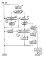
- Fig. 4 is a simplified illustration of the logic flow diagram of the master multiplex controller 10, 110 in accordance with the protocol/format of the invention
- Figs. 5A and 5B are the comparable logic flow diagram for a representative remote controller 12.
- the logic flow diagrams of Figs. 4, 5A and 5B are essentially self-explanatory in view of the disclosure contained hereinbefore, an additional brief description of those routines may assist in a more complete understanding of the invention.
- the initial step 44 consists of generating and applying a continuous series of binary ls to the MUX data line 22 to mark those periods of latency during which no transaction is occurring on the data bus.
- the master controller subsequently selects a particular address of a remote controller 12 and a command to be transmitted to that remote controller.
- the selection of that address and command is determined by a master control program in the master controller and as a function of certain response data received from remote controllers on preceding transactions.
- a transaction is initiated by the generation and transmission of a sync byte, as represented by step 46. Completion of transmission of the sync byte occurs at time T 1 .
- the sync byte is followed by a generation and transmission of an address byte for a remote controller having a particular address i, as represented by step 47.
- the command byte is generated and transmitted as represented by step 48, steps 47 and 48 being completed at times T 2 and T 3 respectively.
- the master controller 10, 110 will also be calculating an error check byte as represented by step 49. That error check byte is transmitted immediately thereafter in the interval between T 3 and T 4 as represented by step 50.
- the master controller 10, 110 receives a remote address byte, as represented by step 51.
- the master controller will also receive the response byte from the remote controller, as indicated by step 52.
- the master controller 10, 110 will be calculating an error check byte based on the re - ceived remote address and response bytes, as represented by step 53.
- the error check byte from the remote controller is received, as represented by step 54.
- the received error check byte is then compared with the internally calculated error check byte, as represented by step 55. If the two error checks agree, then the received remote address is compared with the address byte which had been transmitted by the master controller 10, 110 in its command message, as represented by step 56. Further assuming they agree, the response received from the remote controller is compared with that which is anticipated for the particular command which had been transmitted by the master controller in its command message, as represented by step 57. Again assuming agreement, as would be the case in an error-free transaction, a flag is set indicating the transaction was satisfactory, as represented by step 58. Correspondingly, a "try" counter is set to 0 as represented by step 59 and the routine returns to the marking latency represented by step 44 but which may be immediately replaced with a newly selected address and command as represented by step 45.
- a flag is set indicating that the transaction was not O.K., as represented by step 60, whereupon a "try” counter is incremented by a count of 1, as represented by step 61.
- the "try” count is then compared with a maximum “try” count, as represented by step 62.
- a typical "try” count maximum might be two. Assuming the number of tried attempts at agreement of steps 55, 56 and 57 is less than the "try” count maximum, the routine will return to step 46 to reinitiate the same transaction. On the other hand, if the "try" count exceeds the maximum, the "try” count is reset to 0 as represented by step 59 and the system will move forward to select the next address and command.
- a bit on the MUX data line 22 is shifted-into an input register as by step 65.
- the input register is typically 8 bits in length and receives a serial input from the MUX data line 22.
- a Sync Search Flag is set at 1 during those intervals of bus latency in which the remote controllers awaiting a sync byte and is at 0 during those intervals from T 1 to T 7 in which a transaction is occurring, as represented by step 66.
- the input register or shifter will be monitored to see whether or not its 8 bit contents correspond with a sync byte, i.e., 01101000, as represented by step 67. Assuming the sync byte is not entering or has not yet fully entered the input register, it will continue to shift in bits at step 65 and continue to look for a complete Sync byte. When a full Sync byte has entered the register, as at time T 1 , the Search Sync Flag will be set to 0, as represented by step 68. Successive bits shifted into the input register will then be tested to see if a complete 8 bit byte has been inputted, as represented by step 69.
- step 70 determines whether or not it is the first byte following the Sync byte. Assuming it is the first byte, the contents of the input register are compared with the particular address of the remote controller 12, as at step 71, and assuming agreement a flag is set in that particular remote controller, as represented by step 72, indicating an active transaction addressed to that specific remote controller. On the other hand, if the addresses do not compare, the search sync is reset to one and represented by step 73, and the particular remote controller returns to a standby state awaiting another sync byte and its specific address.
- a subsequent byte from step 69 will be analyzed to determine whether or not it is a second byte in the message as represented by step 74. Assuming the answer is yes, that second byte is identified as a command byte and is saved, as represented by step 75 at time T 3 . Immediately,- the remote controller will begin calculating its error check byte, as represented by step 76. It will be understood that such an error check calculation can be made because the command byte has been saved at step 75 and each remote controller inherently knows its own address.
- step 77 which is completed at time T 4.
- the error check transmitted to the remote controller and saved by step 77 at T 4 is compared at step 78 with the error check byte calculated internally by step 76.
- the command byte saved at step 75 is inspected at step 79 to determine whether or not it is of an input type.
- the input switches or sensors to the particular remote controller provide the basis for a response byte, indicated by step 80, which is subsequently transmitted as part of the reply message.
- the command is not of the input type, it is inspected by step 81 to determine whether or not it is of the output type.
- a response byte will be formulated which comprises a negative acknowledgment, as represented by step 82. It will be noticed that in the event the error check of step 78 does not represent equality, the negative acknowledgment response of step 82 is also appropriate.
- the command byte is of the output type, as determined by step 81, the byte will be decoded and the command executed as represented by step 83, typically in the form of toggling an output.
- a positive acknowledge response is formulated by step 84. All of the foregoing decisions and functions have been effected substantially at the instant designated by time T 4 .
- the address of the particular remote controller is transmitted, as by step 85 completed at time T 5 , and is in turn followed by transmission of the appropriate positive or negative acknowledge response byte, as represented by step 86 completed at time T 6 .
- the remote controller 12 will be calculating an error check byte as represented by step 87 which occupies the interval between T 4 and T 6 .
- the calculated error check byte is then transmitted, as represented by step 88 completed at time T 7 , the time T 7 the search sync flag is set to 1 by step 89, the active transaction flag is set to 0 by step 90, and the input shifter or register is set to all ls as represented by step 91, to reenter a period of standby during bus latency at a waiting receipt of the next sync byte.
Abstract
Description
- The invention relates to an automotive vehicle electrical system and more particularly to a multiplex system for use in an automotive vehicle electrical system. More particularly still, the invention relates to a serial protocol/format for a multiplex system.
- The use of serial time-multiplexed communications of control signals has been known in various vehicular systems, one recent example appearing in U.S. Patent 4,365,694 to Bittar for Preventing Elevator Car Calls Behind Car.
- Various systems have been disclosed for transmitting control data in a serial multiplex fashion between one or more transmitters and one or more receivers in automotive vehicle electrical systems, one relatively early example being illustrated in U.S. Patent 3,742,447 to Sognefest et al.
- Continued development of multiplex systems has placed emphasis on factors such as improved relia- bility and performance. Specifically, the automotive vehicle environment is a very difficult one in which to operate the complex electronic circuits which comprise the current multiplex systems. In that regard, effort has been devoted to reducing the effects of electrical noise, such as electromagnetic interference.
- In U.S. Patent 4,276,640 to McNamee et al, there is disclosed a noise tolerant multiplex system having a transmitter and a receiver, and in which the transmitter includes a tri-state driver for generating a three-level serial data output signal indicative of the status of input switches. The data is generated at a high rate to eliminate any deleterious effects of noise on the system. Specifically, when an input switch is closed, the resulting serial data is transmitted to the receiver at a rate of 10,000 times per second, and the transmission continues as long as the input switch remains closed. Because of this high update rate, occasional incorrect data resulting from noise transients is replaced by correct control data, and the slow-responding loads, such as motors, respond in a correct manner.
- Another system is disclosed in U.S. Patent 4,302,841 to McCulloch in which a microprocessor based transmitter utilizes a serial data line for transmitting data to a plurality of load-controlling receivers connected therealong. The transmitter responds to the states of a plurality of control switches to produce a sequence of digital messages, or words, each containing an address byte, or code, and a command byte, or code. Each receiver includes address code recognition means, and operates to control the associated loads in accordance with the command code included in the same word as its address code. Moreover, the transmitter is such that each word of the digital sequence contains in addition to the address code and the command code, a repetition of one code and the inverse of the other code. Each receiver is capable of checking that each code is consistent with its repetition or inverse. Each receiver is also capable of sending a reply code to the transmitter signifying that the loads controlled by that receiver are appropriately energized. Specifically, each word produced by the transmitter contains, in order, the address code, a repetition of the address code, the command code and the inverse of the command code. The receiver may refuse to receive the command code and its inverse unless it has received the appropriate address code twice. This system achieves a level of noise immunity since each receiver only receives command data when the address data has already been checked.
- The multiplex system of the aforementioned U.S. Patent 4,276,640 is intended for use in a single-receiver system and places reliance upon the relatively slow response rates of the loads and a relatively rapid, repeated data rate to minimixe the effects of noise. Such constraints may be unacceptable in a system requiring several receivers and/or a slower data rate. Moreover, it is unclear how the system responds when two or more input switches are closed concurrently.
- The system of the aforementioned U.S. Patent 4,302,841 provides for transmitting data to each of several receivers, and it formats the data in such a way that circuitry associated with the receiver may, under certain circumstances, determine that an incorrect signal has been received and close down the receiver. However, that system possesses certain characteristics which might be viewed as limitations in certain circumstances. For instance, without a reply address the transmitter does not know which receiver is responding; there is no provision for receiving switch inputs at the receivers; two-bit errors might go unnoticed; and the overhead for error checking is one hundred percent, with an error byte for each message byte.
- It is a principal object of the present invention to provide an improved serial multiplex system for use in an automotive vehicle electrical system. Included within this object is the provision of a multiplex system having improved security against interference from electrical noise.
- It is a further object of the invention to provide an improved multiplex system having stringent error detection/rejection capabilities included in the serial communications protocol/format. Included in this object is a protocol/format suitable for addressing a plurality of remote controllers from a master controller.
- In accordance with the present invention, there is provided for use in an automotive vehicle electrical system, a serial multiplex system having a master controller, a plurality of remote controllers and an improved serial data protocol/format between the controllers for improving the system's security against interference from electrical noise. Stringent error detection and rejection capabilities are provided in the communications protocol/format. As used herein, "protocol" refers to the line discipline or set.of rules that are followed by interconnected devices on the bus in order to insure the orderly transfer of information, and "format" refers to the number of bits per transmission on the bus.
- More particularly, the master controllers and remote controllers are structured to interact with a protocol/format which comprises successive transactions between the master controller and respective ones of the remote controllers. Each transaction is bidirectional and comprises a multibyte command message from the master controller to a particular remote controller, and a multibyte reply message in the reverse direction. The command message includes a particular address byte for a particular intended remote controller, and a command byte. The reply message includes the particular address byte of the particular answering remote controller, and a response byte indicative of a response to the command received by answering remote controller. The response may indicate the response of an output device to a command or it may reveal an input from an input device. The master controller includes the capability of verifying that the address byte received in the reply corresponds with that transmitted in the command message, and that the response byte received in the reply is indicative of the anticipated response to the command byte transmitted in the command message. Absent such verification, the master controller will at least once repeat transmission of the command message.
- Further, the master controller and each of the remote controllers has the dual capability of calculating an error check byte for transmission and of calculating an error check byte for comparison with a received error check byte. Thus, each transaction includes an error check byte transmitted as part of the command message and an error check byte transmitted as part of the reply message. Failure of an error check match at the remote controller is reflected in the response byte of the reply message, and failure of an error check match at the master controller is determined there, either one of which events will result in the master controller at least once repeating the command message. A preferred error check is a cyclical redundancy check based on the address and command bytes in the command message, and based on the address and reply bytes in the reply message.
- A multibit sync byte is transmitted by the master controller to initiate each transaction and terminate a possible interval of latency. The sync byte and each byte of the transaction are eight bits in the illustrated embodiment.
-
- Fig. 1 is a block diagram of a vehicle multiplex system in accordance with the invention;
- Fig. 2 is a block diagram of a modified form of the master controller of the multiplex system;
- Fig. 3 is a graphical illustration of the serial data protocol/format of the invention, including a time scale;
- Fig. 4 is a simplified, logic flow diagram of the master multiplex controller in accordance with the protocol/format of the invention; and
- Figs. 5A and 5B in combination comprise a simplified, logic flow diagram of a representative remote multiplex controller in accordance with the protocol/format of the invention.
- Referring initially to Fig. 1, there is illustrated an automotive multiplexer emulator system capable of implementing the serial data protocol/ format of the invention. The multiplexer system includes a
master controller 10 operatively connected to a plurality of remote controllers 12 individually numbered #1 through #n. The remote controllers 12 are each connected to a four-wire multiplex bus extending from themaster controller 10. One conductor inbus 14,wire 16, provides a signal ground to which themaster controller 10 and each of the remote controllers 12 are connected. Another conductor inbus 14,wire 18, conveys a +5V DC voltage level to themaster controller 10 and each of the remote controllers 12 for powering the electronic circuitry of those controllers. The 5V DC supply is obtained from a5V regulator 19 in turn connected to the 12V DC power system 20 of an automotive vehicle. A further conductor inbus 14,wire 22, conveys serial data between themaster controller 10 and the several remote controllers 12 in accordance with the protocol/format of the present invention. A fourth conductor inbus 14,wire 24, conveys the multiplex clock signal from themaster controller 10 to each of the remote controllers 12. - Typically, each of the remote controllers 12 is utilized to receive one or more inputs from various respective vehicle switches and/or sensors, and/or to provide one or more outputs to various respective vehicle loads, thereby to serve the "body electrical" functions of the vehicle. In the embodiment illustrated in Fig. 1, a controller 12 may receive plural (i.e., 4-8) input signals, generally designated 26, and provide plural (i.e., 4-8) output signals, generally designated 28. The inputs may typically come from a variety of manually actuated switches (not shown) for signalling a desired response from a controlled load device such as one or more particular lights, the horn, trunk release, power windows, etc. Load condition sensors (not shown) might also provide inputs which reveal the status of a particular load. The outputs typically effect one or the other of the states of a two-state load device (i.e., on-off, up-down, open-close), however it will be appreciated that control of a load device to more than two states might also be accomplished at the expense of additional data bits. Similarly, it will be appreciated that certain input devices such as sensors may provide an analog signal. Accordingly, it is necessary either internally or externally of the remote controllers 12 to provide for converting certain input signals from analog to digital and certain output signals from digital to analog. In those instances, plural digital data bits may be required to convey the respective input or output information within the multiplex system.
- In addition to the possible need for A to D conversion, there may also be provision for switch debouncing in the instance of the various input switches and output latching in the event of the various output signals to the output loads. As with the A to D conversion, the switch debouncing and the output latching may either be incorporated as a portion of the respective controllers 12 or provided externally thereto, the former being preferred.
- As illustrated in the embodiment of Fig. 1, the
master controller 10 includes a Mostek38P70 microprocessor controller 30. The 38P70 is an eight bit microprocessor in a controller application, providing 32 bidirection I/O lines configured as four-8 bit ports. One of these ports is used for data transfers with the F-6856 SynchronousProtocol Communications Controller 32. Thecommunications controller 32 can provide serial data rates of up to one megabits per second and supports the protocol/format of the present invention. Thecommunications controller 32 provides half duplex operation in the embodiment of Fig. 1. AMostek 2732PROM 34 piggy-backed into themicroprocessor controller 30 provides 4K bytes of memory which is sufficient for the program requirements of themaster controller 10. A fourMHz clock 36 is supplied to themicroprocessor 30 for timing its operation.. Moreover, the 4MHz clock 36 is supplied to aMUX CLK divider 38 to provide the MUX CLK online 24. The MUX CLK is preferably at a frequency at or above the upper end of the audio range but not so high as to create radio interference. A MUX CLK frequency in the range of 15-25 KHz is generally satisfactory. - The
microprocessor 30 controls the operation of thecommunications controller 32 in accordance with a program stored inPROM 34, the portion of that control relevant to the present invention being described later herein with reference to Figs. 3 and 4. Because the multiplexing system of the present invention is operated in the half duplex mode, there is bidirectional data flow ondata line 22. Thus,communication controller 32 includes both a Transmit Signal Output, TSO, and a Receive Signal Input, RSI, connected to theMUX data line 22 via INTEL 8216 transceivers 40. A similar transceiver 40 is connected to the output of theMUX CLK source 38 for the one-way transmission of the MUX CLK online 24 to the various remote controllers 12. - Referring to the remote controllers 12 as depicted in the Fig. 1 embodiment of the multiplex system operated in accordance with the invention, it will be seen that those controllers also employ respective 38P70 microprocessors 30' as well as F-6856 communications controllers 32' and 8216 transceivers 40'. Each of the remote controllers 12 requires less stored program instruction than does the
master controller 10 thus the 2716 PROMs 34' associated with the microprocessors 30' of the remote controllers 12 need only have a 2K byte capacity. The 4MHz clock 36 for the microprocessors 30' may be developed locally at the respective remote controllers 12 and need not be in synchronization with one another nor with the 4MHz clock 36 of themaster controller 10. - Each of the remote controllers 12 illustrated in Fig. l additionally includes an n-bit parallel conditioner circuit 26' to prepare the system's input signals to proper form (digital logic levels) to be read onto the serial data stream. Also, each remote controller 12 provides an n-bit parallel latch circuit 28' to prepare the system's output signals (digital logic levels) to the voltage and current levels required by vehicle loads (lamps, motors, etc.). Each of the
microprocessors 30 and 30' in the master andremote controllers 10 and 12 respectively has one 8 bit port used for data transfer with therespective communications controller 32 or 32' and a second 8 bit port used to interface with the control lines of therespective communications controller 32 or 32'. Moreover, the microprocessors 30' of the remote controllers 12 use the two remaining 8 bit ports to interface with the n-bit parallel circuitry which in turn provide signals to loads or receive signals from switches or sensors externally of the respective controllers. The actual controlling program for thecommunications controllers 32 and 32' requires less than 512 bytes of PROM memory. The control program is interrupt driven and vector called whenever the Receiver Data Available (RDA) or Transmit Buffer Empty (TBM) signal lines ofcommunications controllers 32 or 32' go active. - Referring to Fig. 2, there is illustrated a
master controller 110 for the multiplexing system, which controller is constituted somewhat differently from that of the Fig. 1 embodiment but which operates in generally the same manner as regards the serial protocol/format of the present invention. More specifically, themaster controller 110 comprises a Zilog Z80 microprocessor 130, Read Only Memory (ROM) 134, Random Access Memory (RAM) 135, and a master multiplexer gate array 132. Amaster clock 36 is obtained from a source such as a crystal, not shown, which may form part of themaster controller 110. Themaster clock 36 may have a frequency of about 2.5 MHz and is extended to the microprocessor 130 and the master multiplex 132 such that they may operate at that rate. A : 100MUX CLK divider 138 provides a 25 KHz MUX CLK signal extended to master multiplexer 132, and thence outputted therefrom and frommaster controller 110 online 24. Similarly, the program stored in ROM 124 determines the operation of the microprocessor controller 130 and thus the serial protocol/format of the invention. The master multiplexer gate array 132 is in many respects analogous to thecommunications controller 32 of Fig. 1; however it interacts with the microprocessor 130 at the 2.5 MHz master clock frequency and its logic design is customized to support the serial protocol/ format of this invention. - The master multiplexer 132 provides an interrupt (INT) on
line 137 to the interrupt port INT on microprocessor 130 in order that the microprocessor may respond to communication-initiated interrupts resulting from serial bus communication transactions. The microprocessor 130 employs an executive program fromROM 134 which responds to real time interrupts to perform internal program functions. Various routines are called in timed fashion and/or in response to communication-initiated interrupts in order to determine a particular command to be sent from the master controller to a remote controller having a particular address. A particular protocol/format is established and observed in transactions between the master controller and a respective remote controller in accordance with the invention, that protocol/format being the same in both the Fig. 1 and the Fig. 2 multiplexer embodiments. The master multiplexer 132 includes logic capable of providing the logic flow routine described hereinafter with reference to Fig. 4. - Although not included in the Fig. 2 illustration, the remote controllers with which
master controller 110 communicates and interacts are functionally similar to remote controllers in Fig. 1; however they may take the form of single-chip integrated circuits which include logic circuits implemented in gate array technology, or other suitable large-scale integrated circuit technology capable of providing the logic flow routine described hereinafter with reference to Figs. 5A and 5B. Thus, the remote controllers associated with themaster controller 110 of Fig. 2 may not require the respective microprocessors, read only memory and separate high frequency clocks associated with controllers 12 of Fig. 1. It should be noted that the remote controllers 12 of Fig. 1, or those associated with the Fig. 2 master controller, each have a particular different address programmed or hardwired thereinto. - Generally speaking, the protocol/format of the invention ensures that serial data communication can occur in the vehicle-installed distributed intelligence multiplex system described previously, in a manner which will permit undegraded system functionality, even in the presence of random vehicle electromagnetic interference. The protocol/format establishes a hierarchy of error check levels which complement the intelligence of the distributed serial multiplex system. Bus communication transactions that have degraded fidelity due to vehicle EMI transients, or "noise", are unable to affect the control of system inputs and outputs, thereby preserving functional integrity of the system.
- Referring to Fig. 3, there is illustrated the preferred protocol/format of the invention, although alternative formats in terms of expanded address, command, and error check bytes are also possible. A tight "handshake"transaction protocol is established. Each communication transaction that occurs on the
serial bus 14 consists of two distinct sections. The first part of a transaction is a "command" transmission or message, issued by themaster controller master controller master controller - An important aspect of the protocol/format is the provision of error checking which occurs at three levels: hardware checks, address checks, and command/response correlation, to be discussed hereinafter in greater detail.
- In the protocol/format illustrated in Fig. 3, a typical bus transaction #n is comprised of 7 bytes, each byte consisting of 8 bits. An initial Sync byte is followed in sequence by a Master's MUX Address byte, a Master's MUX Command byte, a Master's Cyclical Redundancy Check (CRC) byte, a Remote's MUX Address byte, a Remote's MUX Response byte and a Remote's CRC. The Master's MUX Address byte represents the byte generated by
master controller - In each bus transaction, the Command message is immediately followed by a Reply Message which is provided by the particular remote controller 12 which responds to the address contained in the Command Message as received at the remote controllers. In the absence of noise or other errors, the responding remote controller 12 will thus be the controller whose address was initially transmitted in the command message by the
master controller - Referring to the time scale in Fig. 3, and assuming a 25 KHz MUX CLK rate, each 8 bit byte will require 0.32 milliseconds, such that Tl occurs 0.32 milliseconds after TO and a full transaction, i.e., TO-T7 requires 2.24 milliseconds, thus affording nominally 400 transactions per second.
- Error checking in the present system occurs on three levels: hardware checks, address checks, and command/response correlation. The hardware checks are implemented via the cyclic redundancy methods. Each remote multiplex controller 12 and the
master multiplex controller master controller master controller master controller master controller - Address checks are implemented on both the hardware and software level in the present system. Each remote controller 12 is wired via printed circuit board pattern to respond to a unique 8 bit address in the system, thereby permitting an address space of 256 possible remote controllers 12. When the
master controller - The
master controller master controller master controller master controller write 1" case and a (OF) in hexidecimal = (00001111) in binary for the "write 0" case. Failure of the Response byte for an output mode command to correlate will result in themaster controller - In the event a diagnostic mode is employed in the system, the Positive Acknowledge response byte to a diagnostic mode command may be a series of alternating ls and Os if the remote multiplex address is even and a series of alternating Os and ls if the remote address is odd. Note that in each of the four aforementioned Positive Acknowledge response bytes that it requires 8 bit errors simultaneously before any of those bytes can be confused with one another.
- If an input mode command is sent to a remote controller 12, the response byte indicates the state of 8 input devices applied to that controller. Switches are debounced to eliminate transient multiple edges from being reported in response bytes. Depending upon the application, at least two correlation methods can be employed for input response bytes. Specifically, for fairly rapidly changing input switches, two bits per switch can be employed so that the
master controller master controller - Fig. 4 is a simplified illustration of the logic flow diagram of the
master multiplex controller master controller initial step 44 consists of generating and applying a continuous series of binary ls to theMUX data line 22 to mark those periods of latency during which no transaction is occurring on the data bus. As indicated bystep 45, the master controller subsequently selects a particular address of a remote controller 12 and a command to be transmitted to that remote controller. The selection of that address and command is determined by a master control program in the master controller and as a function of certain response data received from remote controllers on preceding transactions. A transaction is initiated by the generation and transmission of a sync byte, as represented by step 46. Completion of transmission of the sync byte occurs at time T1. The sync byte is followed by a generation and transmission of an address byte for a remote controller having a particular address i, as represented bystep 47. Immediately thereafter the command byte is generated and transmitted as represented bystep 48, steps 47 and 48 being completed at times T2 and T3 respectively. In the interval between T1 and T3 themaster controller step 49. That error check byte is transmitted immediately thereafter in the interval between T3 and T4 as represented bystep 50. At time T4 one of the remote controllers 12 should be responding and accordingly themaster controller step 51. Subsequently, in the interval between T5 and T6, the master controller will also receive the response byte from the remote controller, as indicated bystep 52. During the interval from T4 to T6, themaster controller step 53. In the interval between T6 and T7, the error check byte from the remote controller is received, as represented bystep 54. The received error check byte is then compared with the internally calculated error check byte, as represented bystep 55. If the two error checks agree, then the received remote address is compared with the address byte which had been transmitted by themaster controller step 56. Further assuming they agree, the response received from the remote controller is compared with that which is anticipated for the particular command which had been transmitted by the master controller in its command message, as represented bystep 57. Again assuming agreement, as would be the case in an error-free transaction, a flag is set indicating the transaction was satisfactory, as represented bystep 58. Correspondingly, a "try" counter is set to 0 as represented bystep 59 and the routine returns to the marking latency represented bystep 44 but which may be immediately replaced with a newly selected address and command as represented bystep 45. - In the event any one of the three comparisons represented by the
steps step 60, whereupon a "try" counter is incremented by a count of 1, as represented bystep 61. The "try" count is then compared with a maximum "try" count, as represented bystep 62. A typical "try" count maximum might be two. Assuming the number of tried attempts at agreement ofsteps step 59 and the system will move forward to select the next address and command. - Referring to the flow diagram of Figs. 5A and 5B associated with the logic of each respective remote controller 12, a bit on the
MUX data line 22 is shifted-into an input register as bystep 65. The input register is typically 8 bits in length and receives a serial input from theMUX data line 22. A Sync Search Flag is set at 1 during those intervals of bus latency in which the remote controllers awaiting a sync byte and is at 0 during those intervals from T1 to T7 in which a transaction is occurring, as represented bystep 66. Assuming the remote controller is awaiting a sync byte, the input register or shifter will be monitored to see whether or not its 8 bit contents correspond with a sync byte, i.e., 01101000, as represented bystep 67. Assuming the sync byte is not entering or has not yet fully entered the input register, it will continue to shift in bits atstep 65 and continue to look for a complete Sync byte. When a full Sync byte has entered the register, as at time T1, the Search Sync Flag will be set to 0, as represented bystep 68. Successive bits shifted into the input register will then be tested to see if a complete 8 bit byte has been inputted, as represented bystep 69. Once a full byte has been inputted, it is checked bystep 70 to determine whether or not it is the first byte following the Sync byte. Assuming it is the first byte, the contents of the input register are compared with the particular address of the remote controller 12, as atstep 71, and assuming agreement a flag is set in that particular remote controller, as represented by step 72, indicating an active transaction addressed to that specific remote controller. On the other hand, if the addresses do not compare, the search sync is reset to one and represented bystep 73, and the particular remote controller returns to a standby state awaiting another sync byte and its specific address. - Assuming that a particular remote controller 12 has received its address in the first command message byte and has identified that it is within an active transaction, a subsequent byte from
step 69 will be analyzed to determine whether or not it is a second byte in the message as represented bystep 74. Assuming the answer is yes, that second byte is identified as a command byte and is saved, as represented bystep 75 at time T3. Immediately,- the remote controller will begin calculating its error check byte, as represented bystep 76. It will be understood that such an error check calculation can be made because the command byte has been saved atstep 75 and each remote controller inherently knows its own address. - Assuming the incoming data is no longer the second byte, it presumably is the third byte, which represents the error check byte transmitted with the command message, and is correspondingly saved, as represented by
step 77 which is completed at time T 4. - Referring to Fig. 5B, the error check transmitted to the remote controller and saved by
step 77 at T4 is compared atstep 78 with the error check byte calculated internally bystep 76. Assuming equality, the command byte saved atstep 75 is inspected atstep 79 to determine whether or not it is of an input type. Assuming the command is of the input type, the input switches or sensors to the particular remote controller provide the basis for a response byte, indicated bystep 80, which is subsequently transmitted as part of the reply message. On the other hand, if the command is not of the input type, it is inspected bystep 81 to determine whether or not it is of the output type. Assuming the command is not of the output type and assuming that in the embodiment under discussion there is no provision for a diagnostic response, a response byte will be formulated which comprises a negative acknowledgment, as represented bystep 82. It will be noticed that in the event the error check ofstep 78 does not represent equality, the negative acknowledgment response ofstep 82 is also appropriate. Assuming the command byte is of the output type, as determined bystep 81, the byte will be decoded and the command executed as represented bystep 83, typically in the form of toggling an output. Correspondingly, a positive acknowledge response is formulated bystep 84. All of the foregoing decisions and functions have been effected substantially at the instant designated by time T 4. - Subsequently, the address of the particular remote controller is transmitted, as by
step 85 completed at time T5, and is in turn followed by transmission of the appropriate positive or negative acknowledge response byte, as represented bystep 86 completed at time T6. The remote controller 12 will be calculating an error check byte as represented bystep 87 which occupies the interval between T4 and T6. The calculated error check byte is then transmitted, as represented bystep 88 completed at time T7, the time T7 the search sync flag is set to 1 bystep 89, the active transaction flag is set to 0 bystep 90, and the input shifter or register is set to all ls as represented bystep 91, to reenter a period of standby during bus latency at a waiting receipt of the next sync byte. - Although this invention has been shown and described with respect to detailed embodiments thereof, it will be understood by those skilled in the art that various changes in form and detail thereof may be made without departing from the spirit and scope of the claimed invention.
- Having thus described a typical embodiment of the invention, that which is claimed as new and desired to be secured by Letters Patent of the United States is:
Claims (14)
Applications Claiming Priority (2)
| Application Number | Priority Date | Filing Date | Title |
|---|---|---|---|
| US06/469,591 US4534025A (en) | 1983-02-24 | 1983-02-24 | Vehicle multiplex system having protocol/format for secure communication transactions |
| US469591 | 1983-02-24 |
Publications (3)
| Publication Number | Publication Date |
|---|---|
| EP0117832A2 true EP0117832A2 (en) | 1984-09-05 |
| EP0117832A3 EP0117832A3 (en) | 1986-07-16 |
| EP0117832B1 EP0117832B1 (en) | 1988-11-17 |
Family
ID=23864353
Family Applications (1)
| Application Number | Title | Priority Date | Filing Date |
|---|---|---|---|
| EP84630013A Expired EP0117832B1 (en) | 1983-02-24 | 1984-02-03 | Vehicle multiplex system having protocol/format for secure communication transactions |
Country Status (6)
| Country | Link |
|---|---|
| US (1) | US4534025A (en) |
| EP (1) | EP0117832B1 (en) |
| JP (1) | JPS59163697A (en) |
| CA (1) | CA1210169A (en) |
| DE (1) | DE3475176D1 (en) |
| ES (2) | ES529979A0 (en) |
Cited By (21)
| Publication number | Priority date | Publication date | Assignee | Title |
|---|---|---|---|---|
| EP0138735A2 (en) * | 1983-10-07 | 1985-04-24 | UNITED TECHNOLOGIES AUTOMOTIVE, Inc. | Multiplex control system having enhanced integrity |
| FR2578070A1 (en) * | 1985-02-22 | 1986-08-29 | Bosch Gmbh Robert | METHOD FOR OPERATING A DATA PROCESSING FACILITY FOR MOTOR VEHICLES |
| EP0193485A1 (en) | 1985-02-26 | 1986-09-03 | UNITED TECHNOLOGIES AUTOMOTIVE, Inc. | Load current management system for automotive vehicles |
| EP0192819A2 (en) * | 1985-02-23 | 1986-09-03 | Hitachi, Ltd. | Collective wiring system and method of control thereof |
| EP0230203A2 (en) * | 1985-12-13 | 1987-07-29 | UNITED TECHNOLOGIES AUTOMOTIVE, Inc. | Multiplex control system for memory seat or the like load |
| GB2186404A (en) * | 1986-02-06 | 1987-08-12 | Notifier Co | Security system with signal accuracy checking |
| EP0243811A2 (en) * | 1986-04-30 | 1987-11-04 | Koenig & Bauer Aktiengesellschaft | Control device for rotary printing machines |
| EP0247862A2 (en) * | 1986-05-27 | 1987-12-02 | Nohmi Bosai Kogyo Co., Ltd. | Disaster prevention monitoring and control facility |
| EP0295897A2 (en) * | 1987-06-17 | 1988-12-21 | Ford Motor Company Limited | Multiplex wiring system |
| EP0309302A2 (en) * | 1987-08-27 | 1989-03-29 | Automated Process Control, Inc. | Interchange system between logic modules |
| FR2623674A1 (en) * | 1987-11-25 | 1989-05-26 | Peugeot | INFORMATION TRANSMISSION DEVICE FOR A MOTOR VEHICLE AND METHOD FOR IMPLEMENTING SUCH A DEVICE |
| EP0325592A1 (en) * | 1986-08-26 | 1989-08-02 | Slope Indicator Co | Digitally based system for monitoring physical phenomena. |
| EP0406718A2 (en) * | 1989-07-01 | 1991-01-09 | Bayerische Motoren Werke Aktiengesellschaft, Patentabteilung AJ-3 | Communication method for a single wire data bus for a motor vehicle |
| EP0422507A2 (en) * | 1989-10-09 | 1991-04-17 | Nissan Motor Co., Ltd. | System and method for communicating data between control unit and master station applicable to automotive vehicle |
| EP0425199A2 (en) * | 1989-10-27 | 1991-05-02 | Hitachi, Ltd. | Motor vehicle control system and control unit thereof |
| US5046041A (en) * | 1987-12-17 | 1991-09-03 | Automobiles Peugeot | Device for transmitting information between a plurality of elements of an automobile vehicle, and a central information processing unit |
| EP0470056A2 (en) * | 1990-07-30 | 1992-02-05 | MARELLI AUTRONICA S.p.A. | A system for transmitting signals, particularly in motor vehicles, and a method for its operation |
| EP0491095A1 (en) * | 1990-12-17 | 1992-06-24 | UNITED TECHNOLOGIES AUTOMOTIVE, Inc. | Single wire, infrared randomly reflected, automotive multiplexing system |
| GB2266392A (en) * | 1992-04-16 | 1993-10-27 | Equus Inc | A three-line type of vehicle burglarproof system. |
| EP0829394A1 (en) * | 1996-09-17 | 1998-03-18 | Automobiles Peugeot | Method and device for synchronising the operation of at least two computers in an on-board motor vehicule electronics system |
| GB2291568B (en) * | 1994-07-22 | 1998-10-14 | Mitsubishi Electric Corp | Master-slave data communication system |
Families Citing this family (42)
| Publication number | Priority date | Publication date | Assignee | Title |
|---|---|---|---|---|
| US4698748A (en) * | 1983-10-07 | 1987-10-06 | Essex Group, Inc. | Power-conserving control system for turning-off the power and the clocking for data transactions upon certain system inactivity |
| US4622551A (en) * | 1983-10-27 | 1986-11-11 | Otis Elevator Company | Half-duplex industrial communications system |
| US4771425A (en) * | 1984-10-29 | 1988-09-13 | Stratacom, Inc. | Synchoronous packet voice/data communication system |
| US4819228A (en) * | 1984-10-29 | 1989-04-04 | Stratacom Inc. | Synchronous packet voice/data communication system |
| US4667191A (en) * | 1984-12-21 | 1987-05-19 | Motorola, Inc. | Serial link communications protocol |
| DE3540599A1 (en) * | 1985-11-15 | 1987-05-21 | Porsche Ag | DIAGNOSTIC SYSTEM FOR A MOTOR VEHICLE |
| US5040168A (en) * | 1989-06-30 | 1991-08-13 | United Technologies Automotive, Inc. | Single wire, infrared, randomly reflected, vehicular multiplexing system |
| JPH04114203A (en) * | 1990-09-04 | 1992-04-15 | Fuji Heavy Ind Ltd | On-vehicle electronic control system |
| US5237570A (en) * | 1991-07-18 | 1993-08-17 | Motorola, Inc. | Prioritized data transfer method and apparatus for a radiotelephone peripheral |
| US5297142A (en) * | 1991-07-18 | 1994-03-22 | Motorola, Inc. | Data transfer method and apparatus for communication between a peripheral and a master |
| JPH07505022A (en) * | 1991-11-19 | 1995-06-01 | サイエンティフィック−アトランタ インコーポレイテッド | Method and apparatus for communicating program data signals via remote control unit |
| US5434866A (en) * | 1992-03-27 | 1995-07-18 | Integrated Network Corporation | Digital communication system with intelligent channel units |
| US5262683A (en) * | 1992-04-20 | 1993-11-16 | Ford Motor Company | Method for specifying operating characteristics of integrated circuits |
| WO1993022857A1 (en) * | 1992-05-04 | 1993-11-11 | Ford Motor Company Limited | Slave bus controller circuit for class a motor vehicle data communications |
| US5785532A (en) * | 1993-06-09 | 1998-07-28 | United Technologies Automotive, Inc. | Power distribution box and system |
| EP0701514B1 (en) * | 1993-06-09 | 1997-08-06 | UNITED TECHNOLOGIES AUTOMOTIVE, Inc. | Hybrid junction box |
| US5805402A (en) * | 1993-06-09 | 1998-09-08 | Ut Automotive Dearborn, Inc. | Integrated interior trim and electrical assembly for an automotive vehicle |
| US5764010A (en) * | 1995-04-28 | 1998-06-09 | United Technologies Automotive, Inc. | Control system for an automotive vehicle multi-functional apparatus |
| JP3241980B2 (en) * | 1995-11-20 | 2001-12-25 | アルプス電気株式会社 | Multiplex communication system |
| JP3658696B2 (en) * | 1996-03-29 | 2005-06-08 | 能美防災株式会社 | Disaster prevention equipment |
| US5881063A (en) * | 1996-04-08 | 1999-03-09 | Ford Motor Company | Half-message based multiplex communication interface circuit which uses a main microcontroller to detect a match in addresses and generate a qualified signal |
| US5740189A (en) * | 1996-10-03 | 1998-04-14 | Ford Motor Company | Integrity check method and system for serial-based communication |
| US5957985A (en) * | 1996-12-16 | 1999-09-28 | Microsoft Corporation | Fault-resilient automobile control system |
| JPH10274602A (en) | 1997-03-31 | 1998-10-13 | Toyota Motor Corp | Communication control apparatus for vehicle |
| GB2329074B (en) * | 1997-09-08 | 2002-01-23 | Delco Electronics Europ Gmbh | Electrical distribution system |
| FR2769661B1 (en) * | 1997-10-10 | 1999-12-31 | Peugeot | REMOTE CONTROL / LOCKING SYSTEM FOR THE OPENING ELEMENTS OF A MOTOR VEHICLE |
| US6502197B1 (en) | 1998-11-23 | 2002-12-31 | Cypress Semiconductor Corp. | Method and architecture for synchronizing a transport and path overhead generator and/or extractor to an path overhead transport and path processor |
| US6665265B1 (en) * | 1998-11-23 | 2003-12-16 | Cypress Semiconductor Corp. | Overhead serial communication scheme |
| JP3844904B2 (en) * | 1999-03-31 | 2006-11-15 | 三菱電機株式会社 | Vehicle control communication system |
| US6802917B1 (en) | 2000-05-26 | 2004-10-12 | Integran Technologies Inc. | Perforated current collectors for storage batteries and electrochemical cells, having improved resistance to corrosion |
| US6819657B1 (en) * | 2000-11-16 | 2004-11-16 | Aperto Networks, Inc. | Dynamic link parameter control |
| US20020120421A1 (en) * | 2001-02-27 | 2002-08-29 | Crawford Daniel A. | Controller having internal durability test cycle driver |
| DE10240669A1 (en) * | 2002-09-04 | 2004-03-18 | Wabco Gmbh & Co. Ohg | Message handling procedure for car safety critical system uses message identifiers to send messages on redundant channels |
| US7139613B2 (en) | 2002-09-25 | 2006-11-21 | Medtronic, Inc. | Implantable medical device communication system with pulsed power biasing |
| US7013178B2 (en) | 2002-09-25 | 2006-03-14 | Medtronic, Inc. | Implantable medical device communication system |
| US20080272649A1 (en) * | 2003-10-31 | 2008-11-06 | Johnson Controls Technology Company | Electrical connectivity system for use in a vehicle |
| US7286884B2 (en) | 2004-01-16 | 2007-10-23 | Medtronic, Inc. | Implantable lead including sensor |
| DE102006037125A1 (en) * | 2006-08-09 | 2008-02-14 | Daimler Ag | Drive system for a drive unit of a motor vehicle |
| US7881415B2 (en) | 2006-12-29 | 2011-02-01 | Atmel Corporation | Communication protocol method and apparatus for a single wire device |
| US8396563B2 (en) | 2010-01-29 | 2013-03-12 | Medtronic, Inc. | Clock synchronization in an implantable medical device system |
| KR20130099023A (en) * | 2010-08-03 | 2013-09-05 | 콘티넨탈 테베스 아게 운트 코. 오하게 | Communication method with echo |
| JP5680048B2 (en) * | 2012-11-22 | 2015-03-04 | 株式会社リブ技術研究所 | Automatic control system, contact information collection and distribution device, and slave station of automatic control system |
Citations (4)
| Publication number | Priority date | Publication date | Assignee | Title |
|---|---|---|---|---|
| FR2446554A1 (en) * | 1979-01-15 | 1980-08-08 | Marchal Equip Auto | Monitoring and control circuit for vehicle services - uses single wire for transmitted and received data and for power |
| GB2058418A (en) * | 1979-07-06 | 1981-04-08 | Ward Goldstone Ltd | A multiplex information handling system |
| FR2483646A2 (en) * | 1980-05-29 | 1981-12-04 | Seima | Control unit for motor vehicle electrical equipment - issues binary coded signals for control and test of equipment |
| DE3242380A1 (en) * | 1981-11-25 | 1983-06-01 | Aisin Seiki K.K., Kariya, Aichi | TELEPHONE TRANSMISSION SYSTEM ON A ROAD VEHICLE |
Family Cites Families (7)
| Publication number | Priority date | Publication date | Assignee | Title |
|---|---|---|---|---|
| US3924240A (en) * | 1973-04-09 | 1975-12-02 | Gen Electric | System for controlling processing equipment |
| GB1589748A (en) * | 1976-09-10 | 1981-05-20 | Matsushita Electric Works Ltd | Time division multiplex transmission system |
| US4293947A (en) * | 1977-10-12 | 1981-10-06 | Ford Motor Company | Information handling system |
| GB1602816A (en) * | 1978-03-10 | 1981-11-18 | Ward Goldstone Ltd | Multiplex information handling system |
| GB2043313B (en) * | 1979-02-01 | 1982-10-20 | Ward Goldstone Ltd | Multiplex information handling system |
| US4270205A (en) * | 1979-02-27 | 1981-05-26 | Phillips Petroleum Company | Serial line communication system |
| US4304001A (en) * | 1980-01-24 | 1981-12-01 | Forney Engineering Company | Industrial control system with interconnected remotely located computer control units |
-
1983
- 1983-02-24 US US06/469,591 patent/US4534025A/en not_active Expired - Lifetime
-
1984
- 1984-02-03 EP EP84630013A patent/EP0117832B1/en not_active Expired
- 1984-02-03 DE DE8484630013T patent/DE3475176D1/en not_active Expired
- 1984-02-14 CA CA000447327A patent/CA1210169A/en not_active Expired
- 1984-02-23 ES ES529979A patent/ES529979A0/en active Granted
- 1984-02-24 JP JP59034112A patent/JPS59163697A/en active Granted
-
1985
- 1985-02-01 ES ES540035A patent/ES8605911A1/en not_active Expired
Patent Citations (4)
| Publication number | Priority date | Publication date | Assignee | Title |
|---|---|---|---|---|
| FR2446554A1 (en) * | 1979-01-15 | 1980-08-08 | Marchal Equip Auto | Monitoring and control circuit for vehicle services - uses single wire for transmitted and received data and for power |
| GB2058418A (en) * | 1979-07-06 | 1981-04-08 | Ward Goldstone Ltd | A multiplex information handling system |
| FR2483646A2 (en) * | 1980-05-29 | 1981-12-04 | Seima | Control unit for motor vehicle electrical equipment - issues binary coded signals for control and test of equipment |
| DE3242380A1 (en) * | 1981-11-25 | 1983-06-01 | Aisin Seiki K.K., Kariya, Aichi | TELEPHONE TRANSMISSION SYSTEM ON A ROAD VEHICLE |
Non-Patent Citations (2)
| Title |
|---|
| ELECTRO/81 CONFERENCE RECORD, vol. 6, 7th-9th April 1981, pages 1-10, New York, US; D. FOLKES: "Serial network simplifies the design of multiple microcomputer systems" * |
| PROCEEDINGS OF THE IRE, vol. 49, no. 1, January 1961, pages 228-235, The Institute of Radio Engineers Inc., New York, US; W.W. PETERSON et al.: "Cyclic codes for error detection" * |
Cited By (47)
| Publication number | Priority date | Publication date | Assignee | Title |
|---|---|---|---|---|
| EP0138735A3 (en) * | 1983-10-07 | 1987-06-24 | Essex Group Inc. | Multiplex control system having enhanced integrity |
| EP0138735A2 (en) * | 1983-10-07 | 1985-04-24 | UNITED TECHNOLOGIES AUTOMOTIVE, Inc. | Multiplex control system having enhanced integrity |
| US5901156A (en) * | 1985-02-22 | 1999-05-04 | Robert Bosch Gmbh | Method of processing messages to be transmitted for a data processing arrangement |
| FR2578070A1 (en) * | 1985-02-22 | 1986-08-29 | Bosch Gmbh Robert | METHOD FOR OPERATING A DATA PROCESSING FACILITY FOR MOTOR VEHICLES |
| US5001642A (en) * | 1985-02-22 | 1991-03-19 | Robert Bosch Gmbh | Method for operating a data processing system |
| US5303348A (en) * | 1985-02-22 | 1994-04-12 | Robert Bosch Gmbh | Method of arbitrating access to a data bus and apparatus therefor |
| US5621888A (en) * | 1985-02-22 | 1997-04-15 | Robert Bosch Gmbh | Method of building up messages for driving a data processing arrangement with several stations receiving connected thereto |
| US5640511A (en) * | 1985-02-22 | 1997-06-17 | Robert Bosch Gmbh | Method of arbitrating access to a data bus and apparatus therefor |
| EP0580189A1 (en) * | 1985-02-23 | 1994-01-26 | Hitachi, Ltd. | Method of control of vehicle devices |
| EP0192819A3 (en) * | 1985-02-23 | 1988-07-20 | Hitachi, Ltd. | Collective wiring system and method of control thereof |
| EP0192819A2 (en) * | 1985-02-23 | 1986-09-03 | Hitachi, Ltd. | Collective wiring system and method of control thereof |
| US4969082A (en) * | 1985-02-23 | 1990-11-06 | Hitachi, Ltd. | Control method for a collective wiring system |
| EP0487503A1 (en) * | 1985-02-23 | 1992-05-27 | Hitachi, Ltd. | Collective wiring system and method of control thereof |
| US4855896A (en) * | 1985-02-23 | 1989-08-08 | Hitachi, Ltd. | Collective wiring system and method of control thereof |
| EP0193485A1 (en) | 1985-02-26 | 1986-09-03 | UNITED TECHNOLOGIES AUTOMOTIVE, Inc. | Load current management system for automotive vehicles |
| EP0230203A3 (en) * | 1985-12-13 | 1989-02-22 | United Technologies Automotive, Inc. | Multiplex control system for memory seat or the like load |
| EP0230203A2 (en) * | 1985-12-13 | 1987-07-29 | UNITED TECHNOLOGIES AUTOMOTIVE, Inc. | Multiplex control system for memory seat or the like load |
| GB2186404A (en) * | 1986-02-06 | 1987-08-12 | Notifier Co | Security system with signal accuracy checking |
| EP0243811A2 (en) * | 1986-04-30 | 1987-11-04 | Koenig & Bauer Aktiengesellschaft | Control device for rotary printing machines |
| EP0243811A3 (en) * | 1986-04-30 | 1989-08-09 | Koenig & Bauer Aktiengesellschaft | Control device for rotary printing machines |
| EP0247862A3 (en) * | 1986-05-27 | 1989-01-25 | Nohmi Bosai Kogyo Co., Ltd. | Disaster prevention monitoring and control facility |
| EP0247862A2 (en) * | 1986-05-27 | 1987-12-02 | Nohmi Bosai Kogyo Co., Ltd. | Disaster prevention monitoring and control facility |
| EP0325592A1 (en) * | 1986-08-26 | 1989-08-02 | Slope Indicator Co | Digitally based system for monitoring physical phenomena. |
| EP0325592A4 (en) * | 1986-08-26 | 1991-04-17 | The Slope Indicator Company | Digitally based system for monitoring physical phenomena |
| EP0295897A3 (en) * | 1987-06-17 | 1990-09-05 | Ford Motor Company Limited | Multiplex wiring system |
| EP0295897A2 (en) * | 1987-06-17 | 1988-12-21 | Ford Motor Company Limited | Multiplex wiring system |
| EP0309302A3 (en) * | 1987-08-27 | 1990-09-26 | Robert E. Riley, Jr. | Interchange system between logic modules |
| EP0309302A2 (en) * | 1987-08-27 | 1989-03-29 | Automated Process Control, Inc. | Interchange system between logic modules |
| US4929941A (en) * | 1987-11-25 | 1990-05-29 | Automobiles Peugeot | Device for transmitting items of information for an automobile vehicle and a method of using said device |
| EP0318354A1 (en) * | 1987-11-25 | 1989-05-31 | Automobiles Peugeot | Vehicle data transmission device and method for using said device |
| FR2623674A1 (en) * | 1987-11-25 | 1989-05-26 | Peugeot | INFORMATION TRANSMISSION DEVICE FOR A MOTOR VEHICLE AND METHOD FOR IMPLEMENTING SUCH A DEVICE |
| US5046041A (en) * | 1987-12-17 | 1991-09-03 | Automobiles Peugeot | Device for transmitting information between a plurality of elements of an automobile vehicle, and a central information processing unit |
| EP0406718A3 (en) * | 1989-07-01 | 1991-11-27 | Bayerische Motoren Werke Ag | Communication method for a single wire data bus for a motor vehicle. |
| EP0406718A2 (en) * | 1989-07-01 | 1991-01-09 | Bayerische Motoren Werke Aktiengesellschaft, Patentabteilung AJ-3 | Communication method for a single wire data bus for a motor vehicle |
| EP0422507A3 (en) * | 1989-10-09 | 1991-09-18 | Nissan Motor Co., Ltd. | System and method for communicating data between control unit and master station applicable to automotive vehicle |
| EP0422507A2 (en) * | 1989-10-09 | 1991-04-17 | Nissan Motor Co., Ltd. | System and method for communicating data between control unit and master station applicable to automotive vehicle |
| EP0425199A3 (en) * | 1989-10-27 | 1993-10-13 | Hitachi, Ltd. | Motor vehicle control system and control unit thereof |
| EP0425199A2 (en) * | 1989-10-27 | 1991-05-02 | Hitachi, Ltd. | Motor vehicle control system and control unit thereof |
| EP0470056A2 (en) * | 1990-07-30 | 1992-02-05 | MARELLI AUTRONICA S.p.A. | A system for transmitting signals, particularly in motor vehicles, and a method for its operation |
| EP0470056A3 (en) * | 1990-07-30 | 1993-09-22 | Marelli Autronica S.P.A. | A system for transmitting signals, particularly in motor vehicles, and a method for its operation |
| EP0491095A1 (en) * | 1990-12-17 | 1992-06-24 | UNITED TECHNOLOGIES AUTOMOTIVE, Inc. | Single wire, infrared randomly reflected, automotive multiplexing system |
| GB2266392B (en) * | 1992-04-16 | 1995-10-11 | Equus Inc | A three-line type of vehicle burglar-detecting system |
| GB2266392A (en) * | 1992-04-16 | 1993-10-27 | Equus Inc | A three-line type of vehicle burglarproof system. |
| GB2291568B (en) * | 1994-07-22 | 1998-10-14 | Mitsubishi Electric Corp | Master-slave data communication system |
| US6111889A (en) * | 1994-07-22 | 2000-08-29 | Mitsubishi Denki Kabushiki Kaisha | Master-slave data communication system |
| EP0829394A1 (en) * | 1996-09-17 | 1998-03-18 | Automobiles Peugeot | Method and device for synchronising the operation of at least two computers in an on-board motor vehicule electronics system |
| FR2753551A1 (en) * | 1996-09-17 | 1998-03-20 | Peugeot | METHOD AND DEVICE FOR SYNCHRONIZING THE OPERATION OF AT LEAST TWO COMPUTERS OF AN ELECTRONIC SYSTEM ON BOARD ON BOARD OF A MOTOR VEHICLE |
Also Published As
| Publication number | Publication date |
|---|---|
| JPS59163697A (en) | 1984-09-14 |
| JPH0514960B2 (en) | 1993-02-26 |
| CA1210169A (en) | 1986-08-19 |
| DE3475176D1 (en) | 1988-12-22 |
| EP0117832B1 (en) | 1988-11-17 |
| ES540035A0 (en) | 1986-04-01 |
| ES8605911A1 (en) | 1986-04-01 |
| ES8507748A1 (en) | 1985-10-01 |
| EP0117832A3 (en) | 1986-07-16 |
| ES529979A0 (en) | 1985-10-01 |
| US4534025A (en) | 1985-08-06 |
Similar Documents
| Publication | Publication Date | Title |
|---|---|---|
| US4534025A (en) | Vehicle multiplex system having protocol/format for secure communication transactions | |
| EP0207948B1 (en) | Internally register-modelled, serially-bussed radio system | |
| CA1211236A (en) | Multiplex control system having enhanced integrity | |
| US6353615B1 (en) | Protocol for critical security applications | |
| US4642630A (en) | Method and apparatus for bus contention resolution | |
| WO1986006571A1 (en) | Communication system | |
| JPH0728302B2 (en) | Communications system | |
| US3872437A (en) | Supervisory control system | |
| EP0128406B1 (en) | Data transmission/reception network system | |
| CA2277560A1 (en) | Method of determining a uniform global view of the system status of a distributed computer network | |
| US4242752A (en) | Circuit arrangement for coding or decoding of binary data | |
| US7283488B2 (en) | J1850 application specific integrated circuit (ASIC) and messaging technique | |
| US5636343A (en) | Microcomputer with built-in serial input-output circuit and collision detection circuit responsive to common input-output line being occupied | |
| EP0093578B1 (en) | Communications system | |
| US5463645A (en) | System for detecting non-coincidence of codes | |
| GB2186157A (en) | Terminal for a packet switching network | |
| US5339451A (en) | Data transmission system wherein the setting of the transmit data word number indicates whether a new transmission or retransmission should be sent | |
| JPS5829243A (en) | Signal monitoring device of transmission system | |
| CN114253771A (en) | Output data smooth switching method based on two-by-two-out-of-two safety platform | |
| JP2874983B2 (en) | Communication device | |
| JPH05316125A (en) | Serial multiplex communication system | |
| CN113348648A (en) | Transmitting/receiving device for a subscriber station of a serial bus system and method for communication in a serial bus system | |
| JPS59134944A (en) | Data communication system | |
| JPS58198941A (en) | Simple data transmitter | |
| JPS6394733A (en) | Signal transmission equipment |
Legal Events
| Date | Code | Title | Description |
|---|---|---|---|
| PUAI | Public reference made under article 153(3) epc to a published international application that has entered the european phase |
Free format text: ORIGINAL CODE: 0009012 |
|
| AK | Designated contracting states |
Designated state(s): DE FR GB IT SE |
|
| PUAL | Search report despatched |
Free format text: ORIGINAL CODE: 0009013 |
|
| AK | Designated contracting states |
Kind code of ref document: A3 Designated state(s): DE FR GB IT SE |
|
| 17P | Request for examination filed |
Effective date: 19860903 |
|
| 17Q | First examination report despatched |
Effective date: 19870608 |
|
| R17C | First examination report despatched (corrected) |
Effective date: 19870611 |
|
| GRAA | (expected) grant |
Free format text: ORIGINAL CODE: 0009210 |
|
| AK | Designated contracting states |
Kind code of ref document: B1 Designated state(s): DE FR GB IT SE |
|
| REF | Corresponds to: |
Ref document number: 3475176 Country of ref document: DE Date of ref document: 19881222 |
|
| ET | Fr: translation filed | ||
| ITF | It: translation for a ep patent filed |
Owner name: UFFICIO BREVETTI RICCARDI & C. |
|
| PLBE | No opposition filed within time limit |
Free format text: ORIGINAL CODE: 0009261 |
|
| STAA | Information on the status of an ep patent application or granted ep patent |
Free format text: STATUS: NO OPPOSITION FILED WITHIN TIME LIMIT |
|
| 26N | No opposition filed | ||
| ITTA | It: last paid annual fee | ||
| PGFP | Annual fee paid to national office [announced via postgrant information from national office to epo] |
Ref country code: FR Payment date: 19940114 Year of fee payment: 11 |
|
| PGFP | Annual fee paid to national office [announced via postgrant information from national office to epo] |
Ref country code: SE Payment date: 19940118 Year of fee payment: 11 Ref country code: GB Payment date: 19940118 Year of fee payment: 11 |
|
| PGFP | Annual fee paid to national office [announced via postgrant information from national office to epo] |
Ref country code: DE Payment date: 19940119 Year of fee payment: 11 |
|
| EAL | Se: european patent in force in sweden |
Ref document number: 84630013.5 |
|
| PG25 | Lapsed in a contracting state [announced via postgrant information from national office to epo] |
Ref country code: GB Effective date: 19950203 |
|
| PG25 | Lapsed in a contracting state [announced via postgrant information from national office to epo] |
Ref country code: SE Effective date: 19950204 |
|
| GBPC | Gb: european patent ceased through non-payment of renewal fee |
Effective date: 19950203 |
|
| PG25 | Lapsed in a contracting state [announced via postgrant information from national office to epo] |
Ref country code: FR Effective date: 19951031 |
|
| PG25 | Lapsed in a contracting state [announced via postgrant information from national office to epo] |
Ref country code: DE Effective date: 19951101 |
|
| EUG | Se: european patent has lapsed |
Ref document number: 84630013.5 |
|
| REG | Reference to a national code |
Ref country code: FR Ref legal event code: ST |