EP0107981A2 - A graphic image symbol storage system for interactive video displays - Google Patents
A graphic image symbol storage system for interactive video displays Download PDFInfo
- Publication number
- EP0107981A2 EP0107981A2 EP83306599A EP83306599A EP0107981A2 EP 0107981 A2 EP0107981 A2 EP 0107981A2 EP 83306599 A EP83306599 A EP 83306599A EP 83306599 A EP83306599 A EP 83306599A EP 0107981 A2 EP0107981 A2 EP 0107981A2
- Authority
- EP
- European Patent Office
- Prior art keywords
- viewer
- improvement
- scenes
- storage means
- display
- Prior art date
- Legal status (The legal status is an assumption and is not a legal conclusion. Google has not performed a legal analysis and makes no representation as to the accuracy of the status listed.)
- Withdrawn
Links
- 230000002452 interceptive effect Effects 0.000 title description 2
- 230000015654 memory Effects 0.000 claims abstract description 38
- 230000005055 memory storage Effects 0.000 claims abstract description 18
- 230000004044 response Effects 0.000 claims abstract description 5
- 230000000007 visual effect Effects 0.000 claims abstract description 5
- 230000003287 optical effect Effects 0.000 claims description 2
- 230000008520 organization Effects 0.000 abstract description 13
- 238000004880 explosion Methods 0.000 abstract description 9
- 230000001960 triggered effect Effects 0.000 abstract 1
- 235000015842 Hesperis Nutrition 0.000 description 9
- 235000012633 Iberis amara Nutrition 0.000 description 9
- 244000027321 Lychnis chalcedonica Species 0.000 description 9
- 235000017899 Spathodea campanulata Nutrition 0.000 description 9
- 238000010304 firing Methods 0.000 description 5
- 238000013507 mapping Methods 0.000 description 5
- 239000011295 pitch Substances 0.000 description 5
- 238000000034 method Methods 0.000 description 4
- 230000008901 benefit Effects 0.000 description 3
- 230000008859 change Effects 0.000 description 3
- 230000000694 effects Effects 0.000 description 3
- 235000019642 color hue Nutrition 0.000 description 2
- 230000007547 defect Effects 0.000 description 2
- 238000010586 diagram Methods 0.000 description 2
- 230000002159 abnormal effect Effects 0.000 description 1
- 230000009471 action Effects 0.000 description 1
- 239000002131 composite material Substances 0.000 description 1
- 230000003247 decreasing effect Effects 0.000 description 1
- 230000004048 modification Effects 0.000 description 1
- 238000012986 modification Methods 0.000 description 1
- 230000008569 process Effects 0.000 description 1
- 230000009897 systematic effect Effects 0.000 description 1
Images


Classifications
-
- A—HUMAN NECESSITIES
- A63—SPORTS; GAMES; AMUSEMENTS
- A63F—CARD, BOARD, OR ROULETTE GAMES; INDOOR GAMES USING SMALL MOVING PLAYING BODIES; VIDEO GAMES; GAMES NOT OTHERWISE PROVIDED FOR
- A63F13/00—Video games, i.e. games using an electronically generated display having two or more dimensions
- A63F13/50—Controlling the output signals based on the game progress
- A63F13/52—Controlling the output signals based on the game progress involving aspects of the displayed game scene
-
- A—HUMAN NECESSITIES
- A63—SPORTS; GAMES; AMUSEMENTS
- A63F—CARD, BOARD, OR ROULETTE GAMES; INDOOR GAMES USING SMALL MOVING PLAYING BODIES; VIDEO GAMES; GAMES NOT OTHERWISE PROVIDED FOR
- A63F13/00—Video games, i.e. games using an electronically generated display having two or more dimensions
- A63F13/40—Processing input control signals of video game devices, e.g. signals generated by the player or derived from the environment
-
- A—HUMAN NECESSITIES
- A63—SPORTS; GAMES; AMUSEMENTS
- A63F—CARD, BOARD, OR ROULETTE GAMES; INDOOR GAMES USING SMALL MOVING PLAYING BODIES; VIDEO GAMES; GAMES NOT OTHERWISE PROVIDED FOR
- A63F13/00—Video games, i.e. games using an electronically generated display having two or more dimensions
- A63F13/90—Constructional details or arrangements of video game devices not provided for in groups A63F13/20 or A63F13/25, e.g. housing, wiring, connections or cabinets
- A63F13/95—Storage media specially adapted for storing game information, e.g. video game cartridges
-
- A—HUMAN NECESSITIES
- A63—SPORTS; GAMES; AMUSEMENTS
- A63F—CARD, BOARD, OR ROULETTE GAMES; INDOOR GAMES USING SMALL MOVING PLAYING BODIES; VIDEO GAMES; GAMES NOT OTHERWISE PROVIDED FOR
- A63F2300/00—Features of games using an electronically generated display having two or more dimensions, e.g. on a television screen, showing representations related to the game
- A63F2300/20—Features of games using an electronically generated display having two or more dimensions, e.g. on a television screen, showing representations related to the game characterised by details of the game platform
- A63F2300/206—Game information storage, e.g. cartridges, CD ROM's, DVD's, smart cards
-
- A—HUMAN NECESSITIES
- A63—SPORTS; GAMES; AMUSEMENTS
- A63F—CARD, BOARD, OR ROULETTE GAMES; INDOOR GAMES USING SMALL MOVING PLAYING BODIES; VIDEO GAMES; GAMES NOT OTHERWISE PROVIDED FOR
- A63F2300/00—Features of games using an electronically generated display having two or more dimensions, e.g. on a television screen, showing representations related to the game
- A63F2300/60—Methods for processing data by generating or executing the game program
- A63F2300/66—Methods for processing data by generating or executing the game program for rendering three dimensional images
Definitions
- the present invention relates generally to improvements in graphic image symbol storage systems, and more particularly pertains to new and improved memory mapping schemes for one-dimensional memory storage systems and a storage organization wherein one-dimensional storage systems are utilized in conjunction with other memory means to generate a graphic image or images to be displayed on a CRT screen.
- graphic memory storage systems including one-dimensional memory storage systems such as video disc, magnetic floppy disc and optical disc systems are used as storage for video game displays.
- the graphic image stored on a normal video disc memory system is stored and retrieved sequentially.
- the symbol for each graphic frame which contains all the data for a complete image to be displayed on a CRT for a fraction of a second are normally scanned for display on a CRT, one by one, at an approximate speed e.g.30 frames per second starting from the first frame to the 54,000th frame. It takes thirty minutes to run through all the frames for normal video disc models.
- the usual organization of the frames which determines the time flow of the story line of the display is that the frames of the lower numbers appear first. If frame jumps occur, in other words, there is a gap between sequential frames being displayed, there is a discontinuity in the story line.
- N:0 mode For normal display, the frames are accessed one by one in sequential order. For convenience we will call this the N:l mode. When the frames are being displayed sequentially in reverse order at normal speed we will call the N:-l mode.
- the video disc players that have a fast scan mode generally operate by providing access to every fifth frame sequentially. For fast scan in the forward direction, we will call this mode the N:5 mode.
- a frame display time must be utilized. For example, if a jump sequence of the N:100 or N:-100 mode is used, the frame memory is accessable every other frame time because a frame and a blanking time is needed to move over the range of 100 frames. In this case, only 15 frames per second are displayed. Display qualtiy is decreased due to flickering. This flickering, however, is tolerable and over a period of time becomes unnoticeable. The quality of the display can be improved somewhat by repeating display of the same frame twice during the time required for the jump. Whether this is done or not amounts to a tradeoff between quality and cost in a game environment.
- Jump sequences are employed for special purposes such as fast scanning of the frames in memory, repeating the scene or backing up the time flow. These cases are not the normal game display procedure and viewers notice that the game play is abnormal any time display varies from the N:l mode.
- the hardware utilized includes control switches and/or levers for the players to operate. These control devices are used to change the relative dimensional relation between the player's symbol (such as his ship, man, etc.) and the surrounding symbols (such as enemies, roads, etc.).
- the switches and/or the levers manipulated by the player must provide an immediate response on the CRT. For instance, while driving a car on a road, if the player steers the control lever or steering wheel to the right, the player's car must go to the right of the road, while the road scene must move to the left, keeping his car steady on the CRT.
- a bullet In a shooting game, a bullet must be ejected from the gun immediately after the player actuates the firing button.
- the present invention solves the above- mentioned defects of a hybrid-type system and presents a video game display system at reasonable cost with realistic scenes from movies which utilize the full screen with wide and continuous variations according to the player's control at any given moment.
- a linear memory used to store graphic image symbols is mapped by use of jump sequences to simulate dimensional storage. Each unique jump sequence corresponds to a specific physical movement of the player-manipulated controller, or is dictated by the game program.
- the graphic image symbols for frequently used scenes or images are stored in another memory device and are retrieved as required upon prompting from the player-manipulated controller or by the information contained in the linear memory device.
- This invention utilizes a video disc player which incorporates the feature of a frame jump system with a fairly large range such as from N: ⁇ 50 to N: ⁇ 300.
- the jump range has no specific significance to the present invention. It is simply a matter of compromise between software and hardware considerations with respect to cost.
- a jump range of N: ⁇ 100 has been found to be the most economical and suitable range. Accordingly, all game examples explained hereinafter are based on a jump range of about N: ⁇ 100. In the N: ⁇ 100 mode, if frame scanning is started from the 0 frame, the CRT will display the frames in linear memory in the following order. At every 1/30 of a second:
- FIG. 1 an example of a coordinate map which includes the N:*100 mode is illustrated.
- the map locates the serial frame numbers on the horizontal from 0 to No. 15,000, for example, starting from the right top at 0 and extending to the left to 15,000.
- the horizontal axis illustrates the N:ti00 mode.
- all frame numbers are equivalent to its coordinate point, for example, arbitrary point P is equivalent to frame No. 8763.
- the adjoining point to its left according to the jump sequence is 8863 (N:100).
- the adjoining point to its right is 8663 (N:-100).
- the N:100 mode scans frames to the left, while the N:-100 mode scans frames to the right.
- the scanning of frames in a N:t1 mode is illustrated on the vertical axis starting at the upper right-hand corner from frame 0 and going down to frame 100.
- scanning in the N-1 mode would be upwards from this point, and scanning in the N:l mode would be downwards from this point.
- point P would be frame 63.
- the adjacent point next to it in the N:-l mode would be 62.
- the adjacent point next to it in the N:1 mode would be 64.
- the ability to select four different modes according to the invention allows two different relative relations to be controlled by the vertical scan (N:tl) and two more different relative relations to be controlled by the horizontal scan (N: ⁇ 100).
- N:tl the vertical scan
- N: ⁇ 100 the horizontal scan
- For vertical scan, left and right relation of the viewer and the object can be controlled.
- FIG. 2 a block diagram of a system for video game display which employs the invention is illustrated.
- the game controls are illustrated as being a joystick 1 which has four switches (not shown) and a pushbutton switch 2 which may be used as a firing button.
- the four switches of joystick 1 may correspond to the four scanning modes N:l, N:-1, N:100 and N:-100.
- the pushbutton 2 may be utilized to produce firing trajectories such as AH and BH shown in Figure 6 and Figure 9, for example. Such trajectories of bullets or missiles are ejected from a gun or missile launcher, A and B shown ( Figure 6, Figure 9) of the player's ship.
- the memory disc storage device 3 is activated by the disc player/controller 4.
- the frames retrieved from the memory disc are displayed on CRT 5 through the action of the interface control circuitry of CRT display controller 6.
- the memory disc and disc player/ controller circuitry are devices of the type manufactured by Pioneer Electronics Company.
- the CRT display controller 6 is a microprocessor-based device that provides timing and interface control between the CRT circuitry and the disc player/controller 4 and the fixed image producer 7.
- the fixed image producer 7 generates images that are frequently and intermittently used in the viewing sequence, such as bullet trajectories or scenes of an explosion, for example.
- the circuitry for the fixed image producer provides for the storage of such frames and movement of the stored frames pursuant to game control.
- the fixed image producer is activated either by a control device such as pushbutton 2 or a signal from the disc player/controller 4.
- the trajectories AH and BH shown in Figure 6 and Figure 9 are examples of images which are produced at a fixed position on the CRT by the fixed image producer 7.
- Figure 3 is an example of a coordinate map of the frames stored on the video disc of Figure 2 for a space war game having scenes of the type shown in Figures 4 through 6.
- the object of the game is to have a player in a space vehicle 9 voyage through space where many planets 10, 11, 12 and 13, for example, are floating or moving slowly.
- the player is looking for an enemy ship 8 hiding behind one of the planets for the purpose of shooting it and destroying it.
- the player can pilot his ship 9 to move left, right, backward and forward by operating the joystick 1 which has four switch positions.
- the vertical scan (N: ⁇ l) on the map of Figure 3 is illustrated by the vertical axis which is labeled No. 0 through No. 80.
- the vertical scan produces the left and right movement of the player's ship.
- the horizontal scan (N:t100) is illustrated by the horizontal axis on Figure 3. This is labeled No. 0 through No. 10K.
- the horizontal scan provides for the back and forth movement of the ship.
- Each block in Figure 3 represents a relative position between the player's ship 9 and the planets 10, 11, 12 and 13 of the frame number coincident with the upper right-hand corner of the block.
- block A of Figure 3 shows relative position between the player's ship 9 and the various planets 10, 11, 12 and 13 of frame No. 3590. That is the frame number at point 14.
- N-shaped link 31 represents the relative position between these four main planets which are shown in block A of Figure 3, and in addition are shown in Figures 4, 5 and 6 in pictorial form.
- the relative position of the player's ship 9 with respect to the group of planets changes . gradually from right to left during the display of 100 frames from frame 4500 at the top of the column to frame 4599 at the bottom of the column.
- the center position of the four planets 10, 11, 12 and 13 moves 1% per frame from the farthest left to the farthest right.
- the four planets 10, 11, 12 and 13 also change mutual positions gradually.
- the scenes or frames with the last two numbers 99 and the following 00 do not continue because in all frames at the top of the map the player's ship 9 is at the farthest right, and in all frames at the bottom of the map the player's ship 9 is at the farthest left with respect to the group of planets 10, 11, 12 and 13.
- the top and bottom of the frame map must be fenced in to stop overscan. Also, both sides of the map must be fenced in to limit the memory of the game. For these reasons, all the frames bordering on all four sides have a collision scene to stop the scan at these frames.
- a second example of a game that may be illustrated according to the present invention is a space war shooting game, scenes of which are pictorially illustrated in Figures 8, 9 and 10.
- fire ball- like rockets 21 are ejected from an enemy ship 18 one by one at random to attack the player's ship 19.
- the distance between the enemy ship 18 and the player's ship 19 is constant.
- the player's ship 19, however, can move to the left and to the right to avoid the rockets.
- Figure 7 is the frame map for this game.
- the horizontal axis represents the horizontal scan from frame No. 0 to frame No. 4000. Scanning horizontally creates the left and right movement of the player's ship.
- the vertical scan is illustrated on the vertical axis labelled as frames No. 0 through 80. The vertical scan simply provides a time flow.
- the time flow is beyond the player's control.
- the flow of the game in the N:l mode is automatic and it proceeds regardless of the player's control.
- the N:-l mode wherein the frames are scanned in reverse, is not utilized at all.
- the joystick has an effect on the display only when it is moved to the right and left. Backward and forward movement will have no effect on the display.
- the objective of this game is to shoot down the enemy ship 18, as shown in Figure 9, in a manner similar to that illustrated in Figure 6 of the previous game, while at the same time avoiding the fire ball rockets 21.
- the memory volume for this game is 4000 frames. Each frame or block illustrated in Figure 7 represents the relative relation among or between the player's ship 19, the enemy ship 18 and the fire ball rockets 21 ejected from the enemy ship 18.
- each block represents the relative position of the frame number coincident with the upper right corner of the block where the horizontal and vertical lines meet. In the frame sequences, the distance between the player's ship 19 and the enemy ship 18 is kept constant.
- fire ball rockets 21 move along five trajectories 20.
- One fire ball rocket is on each trajectory line.
- a particular one of these fire ball rockets has a flying cycle of 100 frames.
- the five-digit member in frame No. 200 means that the five fire ball rockets traveled 70%, 30%, 90%, 50% and 10% on their respective trajectories in this frame.
- the number 84062 means the fire ball rockets traveled 80%, 40%, 0%, 60% and 20% on the respective trajectories in this frame.
- Frame 0 means the rocket is at the end of the travel line and also the start of the next rocket cycle, and if the player's ship 19 is at this position, they will collide and . explode as shown by the explosion symbol 17.
- the fire ball rocket 21 is displayed almost full size on the screen when it is closest to the player's ship.
- This visual image has great appeal to a player.
- By horizontally scanning the memory the relative position of the player's ship 19 with respect to the enemy ship 18 changes from the farthest right to the farthest left.
- fences of many asteroids 22 on both right and left sides are used to block the scenes.
- the horizontal scan will be in the N:102 and N:-98 mode instead of N::100 to keep the time flow of the rocket travel during horizontal scan.
- Figure 11 is a pictorial illustration of the frame allocation in gross of all the scenes for each of the games on a disc.
- the 4K block 39 depicting the scenes for game No. 1 is for the space game explained in connection with the memory map of Figure 7 and the pictorial illustrations of Figures 8 through 10.
- the 10K memory block 37 for the scenes of game 2 are for the space war game illustrated with respect to Figure 3 and the pictorial illustrations of Figures 4 through 6.
- a series of scenes for a third game (not illustrated) having for example, a 30K frame requirement 41 is illustrated, as well as an 8K -block 43 for a smaller game.
- The'explosion scenes El, E2 and E3 each take up 0.5K of frame space and are allocated on the memory disc at the end of each game frame sequence.
- the entire storage utilized for scene frames in this example is 53.5K.
- Figure 12 is a flow chart illustration of the space games described above. However, this particular game procedure is not limiting on the invention. Many other applications of the invention described herein are possible. Many other types of games may be played and illustrated according to the present invention. For example, car racing games as well as various sports games and shooting games may utilize the present invention to great advantage. All these games may utilize realistic movie excerpts as actual scenes, for example.
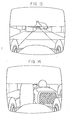
- FIG. 13 through 16 An example of a racing game display is shown in Figures 13 through 16.
- the player drives his car in the foreground steering left and right to avoid colliding with several cars in a group 23.
- Figure 14 When near a collision with a car in front of him ( Figure 14) a huge figure of the other car appears, which the player finds very spectacular.
- This particular game for example, can be laid out in the same manner that the space war game illustrated in the memory map of Figure 7 was laid out.
- the rocket travel of Figure 7 is simply replaced with a racing group of many cars 23.
- the relative positions of the cars in the group change gradually, like the planet positions 10, 11, 12 and 13 of Figure 7 changed.
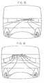
- race course can be changed to a curved one as shown in Figure 15, or an up and down one as shown in Figure 16.
- FIGs 17 and 18 An example of another application of the present invention to illustrate a video game is shown in Figures 17 and 18.
- This game relates to the game of baseball in which the game player can participate by being the batter 26.
- the frames are organized in a typical televised baseball sequence for a variety of pitches coming from the pitcher 24.
- the player as the batter 26 uses a swing button to swing his bat at a time when the ball 25, thrown by a famous pitcher 24, is in the strike zone. The player can let the pitch go by if he thinks it will not be a strike. From the moment that the button to swing the bat is pushed, the display scene changes according to the combination of swing time and the nature of the pitch.
- a variety of pitches may be used, such as a fast ball, screw ball, slow ball, fork ball, knuckle ball, etc., which may result in either a strike or a ball.
- This particular game may be implemented in accordance with the invention by using the swing button to generate scanning in a horizontal direction in an N:102 mode.
- Vertical scan in the N:l mode is for the pitcher's pitching motion and the ball's travel. Scanning in the N:100 and the N:-l mode are not used.
- This game is able to be organized in a 45K frame volume, which provides fifteen kinds of different pitches and 2 seconds of scene after the swing.
Abstract
@ A one-dimensional memory storage device, such as a video disc, is utilized to store graphic image symbols for video game displays. The storage device is organized so that the graphic symbols may be retrieved rapidly enough to give the visual impression that the entire display, including background or scene depiction, is changing in response to the player-manipulated controls. The memory organization scheme utilized establishes a plurality of jump sequences. The particular sequence being utilized to withdraw graphic symbol information from memory is determined by the physical movement of a player-operated control device, i.e., a joystick. Certain frequently used scenes, such as explosions, or bullet or rocket trajectories, for example, are generated separately by a fixed image producer. The graphic image symbols that reproduce such a scene on the CRT scene are stored in a memory in the fixed image producer which is triggered by the information contained on the video disc or by a player-manipulated control device, such as a pushbutton, for example.
Description
- The present invention relates generally to improvements in graphic image symbol storage systems, and more particularly pertains to new and improved memory mapping schemes for one-dimensional memory storage systems and a storage organization wherein one-dimensional storage systems are utilized in conjunction with other memory means to generate a graphic image or images to be displayed on a CRT screen.
- Many different types of graphic memory storage systems including one-dimensional memory storage systems such as video disc, magnetic floppy disc and optical disc systems are used as storage for video game displays. The graphic image stored on a normal video disc memory system is stored and retrieved sequentially. In other words, the symbol for each graphic frame which contains all the data for a complete image to be displayed on a CRT for a fraction of a second are normally scanned for display on a CRT, one by one, at an approximate speed e.g.30 frames per second starting from the first frame to the 54,000th frame. It takes thirty minutes to run through all the frames for normal video disc models. The usual organization of the frames which determines the time flow of the story line of the display is that the frames of the lower numbers appear first. If frame jumps occur, in other words, there is a gap between sequential frames being displayed, there is a discontinuity in the story line.
- Many video disc players have various jump sequence systems available besides a halt condition which gives access and displays a certain frame repeatedly. For convenience, we will call this halt condition the N:0 mode. For normal display, the frames are accessed one by one in sequential order. For convenience we will call this the N:l mode. When the frames are being displayed sequentially in reverse order at normal speed we will call the N:-l mode. The video disc players that have a fast scan mode generally operate by providing access to every fifth frame sequentially. For fast scan in the forward direction, we will call this mode the N:5 mode.
- Considering the performance parameters of a typical video disc player, access to a particular frame can be accomplished without a delay becoming apparent to the viewer within a range of ±15 frames. In other words, the player can move approximately 15 frames in either direction within the blanking time. If access beyond 15 frames is required, a frame display time must be utilized. For example, if a jump sequence of the N:100 or N:-100 mode is used, the frame memory is accessable every other frame time because a frame and a blanking time is needed to move over the range of 100 frames. In this case, only 15 frames per second are displayed. Display qualtiy is decreased due to flickering. This flickering, however, is tolerable and over a period of time becomes unnoticeable. The quality of the display can be improved somewhat by repeating display of the same frame twice during the time required for the jump. Whether this is done or not amounts to a tradeoff between quality and cost in a game environment.
- Jump sequences are employed for special purposes such as fast scanning of the frames in memory, repeating the scene or backing up the time flow. These cases are not the normal game display procedure and viewers notice that the game play is abnormal any time display varies from the N:l mode.
- In a video game system, the hardware utilized includes control switches and/or levers for the players to operate. These control devices are used to change the relative dimensional relation between the player's symbol (such as his ship, man, etc.) and the surrounding symbols (such as enemies, roads, etc.). The switches and/or the levers manipulated by the player must provide an immediate response on the CRT. For instance, while driving a car on a road, if the player steers the control lever or steering wheel to the right, the player's car must go to the right of the road, while the road scene must move to the left, keeping his car steady on the CRT. In a shooting game, a bullet must be ejected from the gun immediately after the player actuates the firing button.
- Conventional video games produce these effects by utilizing simple computer graphics of the symbol patterns on the CRT that are being changed in response to the manipulation of the controls. These are generated by the use of microprocessors and array memories. These computer graphics, however, are all cartoon style and far from the realistic appearance produced by movies or regular broadcast TV.
- There have been video game systems on the market that employed both a computer graphics system and a video disc for the purpose of presenting a video game with a realistic background scene. In these hybrid systems a player's symbol was produced by the computer graphics hardware, while the rest of the scene, including objective patterns, were produced by the video disc system. The two images were simply displayed by superimposing one on the other. The varying locations of the objective patterns (such as enemies, road curves, etc.) in each frame were all memorized in the computer memory rather than in the video disc system, as was the position of the player's symbol. When a player's symbol and the moving objective patterns met on the screen, the disc frame was caused to jump to a separate series of frames to show an explosion or similar scene.
- Since the video disc images and the images retrieved from computer memory were superimposed, the composite scene was not natural in many respects, such as shadows, relative sizes, reflection of light, color hues, brightness, color tone, etc. It was not natural also because the background scene changed constantly to a great extent, while the player's symbol remained fairly stationary. This type of hybrid system is also very expensive because it requires that the location of all the objective patterns in all the frames must be memorized by a computer memory rather than by the video disc memory. This greatly increases the cost of labor and hardware.
- From the standpoint of the viewer or player, however, the defect of this system is that only a small part of the images being displayed is controllable by the manual controls operated by him. From the standpoint of appeal to a viewer/player it is more desirable that his control devices cause direct realistic changes on the screen. For example, if a whole play field scene is controllable by a player as he actually views it from his ship, it is more attractive than if only the player's ship is controllable, while the rest of the scene simply moves along at its own pace, untouchable by the player.
- The present invention solves the above- mentioned defects of a hybrid-type system and presents a video game display system at reasonable cost with realistic scenes from movies which utilize the full screen with wide and continuous variations according to the player's control at any given moment.
- A linear memory used to store graphic image symbols is mapped by use of jump sequences to simulate dimensional storage. Each unique jump sequence corresponds to a specific physical movement of the player-manipulated controller, or is dictated by the game program. The graphic image symbols for frequently used scenes or images are stored in another memory device and are retrieved as required upon prompting from the player-manipulated controller or by the information contained in the linear memory device.
- The objects and many of the attendant advantages of this invention will be readily appreciated as the same becomes understood by reference to the following detailed description when considered in conjunction with the accompanying drawings in which like reference numerals designate like parts throughout the figures thereof, and wherein:
- Figure 1 is a graphic illustration of a jump sequence mapping scheme for a linear memory according to the present invention;
- Figure 2 is a block diagram of a video image display system according to the present inventions
- Figure 3 is a schematic illustration of the frame organization on a linear memory system following a mapping scheme according to the present invention;
- Figure 4 is a pictorial illustration of a video display according to the frame organization shown in Figure 3;
- Figure 5 is a pictorial illustration of a video display according to the frame organization of Figure 3;
- Figure 6 is a pictorial illustration of a video display according to the frame organization of Figure 3;
- Figure 7 is a schematic illustration of the frame organization on a linear memory system following a mapping scheme according to the present invention;
- Figure 8 is a pictorial illustration of a video display according to the frame organization of Figure 7;
- Figure 9 is a pictorial illustration of a video display according to the frame organization of Figure 7;
- Figure 10 is a pictorial illustration of a video display according to the frame organization of Figure 7;
- Figure 11 is a schematic illustration of game scene storage on a linear memory according to the present invention;
- Figure 12 is a flow chart of a game that may utilize the display system of the present invention to great advantage;
- Figure 13 is a pictorial illustration of a scene that may be illustrated according to the present invention;
- Figure 14 is a pictorial illustration of a scene that may be illustrated according to the present invention;
- Figure 15 is a pictorial illustration of a scene that may be illustrated according to the present invention;
- Figure 16 is a pictorial illustration of a scene that may be illustrated according to the present invention;
- Figure 17 is a graphic illustration of a storage scheme for the game illustrated pictorially in Figure 18; and
- Figure 18 is a pictorial illustration of a scene that may be illustrated according to the present invention.
- This invention utilizes a video disc player which incorporates the feature of a frame jump system with a fairly large range such as from N:±50 to N:±300. The jump range has no specific significance to the present invention. It is simply a matter of compromise between software and hardware considerations with respect to cost. A jump range of N:±100 has been found to be the most economical and suitable range. Accordingly, all game examples explained hereinafter are based on a jump range of about N:±100. In the N:±100 mode, if frame scanning is started from the 0 frame, the CRT will display the frames in linear memory in the following order. At every 1/30 of a second:
- No. 0, No. 0, No. 100, No. 100, No. 200, No. 200, No. 400, No. 400, ..... or,
- No. 0, (blank), No. 100, (blank), No. 200, (blank), No. 400, (blank) ...
- In this jump mode it will take about 36 seconds to scan the frames from 0 to 54,000, which is the normal volume of frames on a video disc.
- Referring now to Figure 1, an example of a coordinate map which includes the N:*100 mode is illustrated. The map locates the serial frame numbers on the horizontal from 0 to No. 15,000, for example, starting from the right top at 0 and extending to the left to 15,000. The horizontal axis illustrates the N:ti00 mode. In this manner, all frame numbers are equivalent to its coordinate point, for example, arbitrary point P is equivalent to frame No. 8763. The adjoining point to its left according to the jump sequence is 8863 (N:100). The adjoining point to its right is 8663 (N:-100). In other words, the N:100 mode scans frames to the left, while the N:-100 mode scans frames to the right.
- In the same manner, the scanning of frames in a N:t1 mode is illustrated on the vertical axis starting at the upper right-hand corner from
frame 0 and going down toframe 100. Referring again to a reference point P, scanning in the N-1 mode would be upwards from this point, and scanning in the N:l mode would be downwards from this point. For the example shown, point P would be frame 63. The adjacent point next to it in the N:-l mode would be 62. The adjacent point next to it in the N:1 mode would be 64. In this manner, if the series of the scanned frames which contain the graphic information are systematically arranged so that they look natural and in a normal order of time flow, the viewer is able to select any one of four modes at any time by operating the manually-manipulatable mode switches. - The ability to select four different modes according to the invention allows two different relative relations to be controlled by the vertical scan (N:tl) and two more different relative relations to be controlled by the horizontal scan (N:±100). For example, for horizontal scan, the distance between a viewer and an object in front of the viewer can be controlled. For vertical scan, left and right relation of the viewer and the object can be controlled.
- The horizontal and vertical relations can be exchanged if frame volume of the gradual changes of both scenes is within 100 frames. Other instances of combinations that can be controlled are:
- (1) Up and down relation of viewer and objects/distances between the two;
- (2) Rotational angle of an object/dimensions of the object;
- (3) Color hue graduation of objects/ brightness of it; and
- (4) Fade-in and out of an object/dolly in and out of the object.
- Referring now to Figure 2, a block diagram of a system for video game display which employs the invention is illustrated. The game controls are illustrated as being a
joystick 1 which has four switches (not shown) and apushbutton switch 2 which may be used as a firing button. The four switches ofjoystick 1 may correspond to the four scanning modes N:l, N:-1, N:100 and N:-100. Thepushbutton 2 may be utilized to produce firing trajectories such as AH and BH shown in Figure 6 and Figure 9, for example. Such trajectories of bullets or missiles are ejected from a gun or missile launcher, A and B shown (Figure 6, Figure 9) of the player's ship. - The memory
disc storage device 3 is activated by the disc player/controller 4. The frames retrieved from the memory disc are displayed onCRT 5 through the action of the interface control circuitry ofCRT display controller 6. The memory disc and disc player/ controller circuitry are devices of the type manufactured by Pioneer Electronics Company. TheCRT display controller 6 is a microprocessor-based device that provides timing and interface control between the CRT circuitry and the disc player/controller 4 and thefixed image producer 7. - The
fixed image producer 7 generates images that are frequently and intermittently used in the viewing sequence, such as bullet trajectories or scenes of an explosion, for example. The circuitry for the fixed image producer provides for the storage of such frames and movement of the stored frames pursuant to game control. The fixed image producer is activated either by a control device such aspushbutton 2 or a signal from the disc player/controller 4. The trajectories AH and BH shown in Figure 6 and Figure 9 are examples of images which are produced at a fixed position on the CRT by the fixedimage producer 7. - The organization of the frame sequence stored on the
memory disc 3 is systematic, and according to this invention, in a manner that permits them to be accessed in one of four modes at any time, complying to the operation of thejoystick 1. Figure 3 is an example of a coordinate map of the frames stored on the video disc of Figure 2 for a space war game having scenes of the type shown in Figures 4 through 6. - The object of the game is to have a player in a
space vehicle 9 voyage through space wheremany planets ship 9 to move left, right, backward and forward by operating thejoystick 1 which has four switch positions. - In this particular game, the vertical scan (N:±l) on the map of Figure 3 is illustrated by the vertical axis which is labeled No. 0 through No. 80. The vertical scan produces the left and right movement of the player's ship. The horizontal scan (N:t100) is illustrated by the horizontal axis on Figure 3. This is labeled No. 0 through No. 10K. The horizontal scan provides for the back and forth movement of the ship. Thus, when the
joystick 1 is pushed forward, theplanets ship 9 is advancing forward. When the joystick is pulled backward, the front scene backs up as if the player'sship 9 is backing up. When the joystick is pushed to the left, the whole front scene moves to the right as if theship 9 is moving to the left. When the joystick is pushed to the right the whole front scene made up of theplanets ship 9 is moving to the right. - If a player keeps pushing the joystick forward in spite of the closing in of a planet in front of the ship, the result will be scenes of collision and the consequent explosion. If a player finds an enemy ship 8 (Figure 6) behind a planet he will want to bring its figure to the center H of the CRT screen by piloting his ship left or right. When the trajectories of the firing beams cross at the enemy ship 8 location there will be an explosion of the enemy ship 8 when the
firing button 2 is pushed. These trajectories cross only at the center B of the CRT screen. - A total of 10,000 frames of game scenes are utilized and arranged as shown in the coordinate map of Figure 3. Each block in Figure 3 represents a relative position between the player's
ship 9 and theplanets ship 9 and thevarious planets point 14. - On the column of frame 4500 (two columns to the left of the 3590) ten frames are shown vertically. These frames indicate the gradual changes of the relative positions between the player's
ship 9 and the fourmain planets link 31 represents the relative position between these four main planets which are shown in block A of Figure 3, and in addition are shown in Figures 4, 5 and 6 in pictorial form. - Looking at the ten representative frames in frame column 4500, the relative position of the player's
ship 9 with respect to the group of planets changes . gradually from right to left during the display of 100 frames from frame 4500 at the top of the column to frame 4599 at the bottom of the column. In other words, on the CRT screen the center position of the fourplanets moves 1% per frame from the farthest left to the farthest right. Meanwhile, in the group the fourplanets - On the row of frame Nos. 40, 540, 1040 ....), 9540 and so on, the player's
ship 9 is always almost on the center line of the group of the fourplanets frame 40, to where it almost passes over the next advancing group,frame 9540. - In this kind of layout of frame scenes, the scenes or frames with the last two numbers 99 and the following 00 do not continue because in all frames at the top of the map the player's
ship 9 is at the farthest right, and in all frames at the bottom of the map the player'sship 9 is at the farthest left with respect to the group ofplanets square symbol 15 indicates a collision between the player's ship and one of the various planets. This triggers the explosion sequence, starting with the half collision scene produced by the fixedimage producer 7. - A second example of a game that may be illustrated according to the present invention is a space war shooting game, scenes of which are pictorially illustrated in Figures 8, 9 and 10. In this game fire ball-
like rockets 21 are ejected from anenemy ship 18 one by one at random to attack the player'sship 19. The distance between theenemy ship 18 and the player'sship 19 is constant. The player'sship 19, however, can move to the left and to the right to avoid the rockets. - Figure 7 is the frame map for this game. The horizontal axis represents the horizontal scan from frame No. 0 to frame No. 4000. Scanning horizontally creates the left and right movement of the player's ship. The vertical scan is illustrated on the vertical axis labelled as frames No. 0 through 80. The vertical scan simply provides a time flow.
- According to this game, the time flow is beyond the player's control. In other words, the flow of the game in the N:l mode is automatic and it proceeds regardless of the player's control. The N:-l mode, wherein the frames are scanned in reverse, is not utilized at all. In this instance the joystick has an effect on the display only when it is moved to the right and left. Backward and forward movement will have no effect on the display.
- The objective of this game is to shoot down the
enemy ship 18, as shown in Figure 9, in a manner similar to that illustrated in Figure 6 of the previous game, while at the same time avoiding thefire ball rockets 21. The memory volume for this game is 4000 frames. Each frame or block illustrated in Figure 7 represents the relative relation among or between the player'sship 19, theenemy ship 18 and thefire ball rockets 21 ejected from theenemy ship 18. - In Figure 7, the enemy's
ship symbol 18 is shown placed at the center of each frame block, but in display scenes Figures 8 through 10, the player'sship 19 is always in the center at the bottom. Like the example for the previous game, each block represents the relative position of the frame number coincident with the upper right corner of the block where the horizontal and vertical lines meet. In the frame sequences, the distance between the player'sship 19 and theenemy ship 18 is kept constant. - During the time flow of the vertical scan,
fire ball rockets 21 move along fivetrajectories 20. One fire ball rocket is on each trajectory line. A particular one of these fire ball rockets has a flying cycle of 100 frames. In other words, on the same row of the map the flying phase of the fire ball rockets are all the same, and in each column they fly 1% of the distance per frame from the enemy ship to the player's ship. The five-digit member in frame No. 200 means that the five fire ball rockets traveled 70%, 30%, 90%, 50% and 10% on their respective trajectories in this frame. In the next frame on the vertical axis, thenumber 84062 means the fire ball rockets traveled 80%, 40%, 0%, 60% and 20% on the respective trajectories in this frame. Therefore all these figures in the frames of the row from 0 to 4000 are the same, while the figures in the column, such as frame No. 210 becomes 84062 because the travel distance has advanced 10% from frame No. 200. Thus the time flow continues and from the bottom of the map to the top, it continues also.Frame 0 means the rocket is at the end of the travel line and also the start of the next rocket cycle, and if the player'sship 19 is at this position, they will collide and . explode as shown by theexplosion symbol 17. - As shown in Figure 10 in the scene just before the collision, the
fire ball rocket 21 is displayed almost full size on the screen when it is closest to the player's ship. This visual image has great appeal to a player. By horizontally scanning the memory the relative position of the player'sship 19 with respect to theenemy ship 18 changes from the farthest right to the farthest left. To prevent overscan in this mode, fences ofmany asteroids 22 on both right and left sides are used to block the scenes. The horizontal scan will be in the N:102 and N:-98 mode instead of N::100 to keep the time flow of the rocket travel during horizontal scan. - Figure 11 is a pictorial illustration of the frame allocation in gross of all the scenes for each of the games on a disc. For example, the
4K block 39 depicting the scenes for game No. 1 is for the space game explained in connection with the memory map of Figure 7 and the pictorial illustrations of Figures 8 through 10. The10K memory block 37 for the scenes ofgame 2 are for the space war game illustrated with respect to Figure 3 and the pictorial illustrations of Figures 4 through 6. Likewise, a series of scenes for a third game (not illustrated) having for example, a30K frame requirement 41 is illustrated, as well as an 8K -block 43 for a smaller game. The'explosion scenes El, E2 and E3 each take up 0.5K of frame space and are allocated on the memory disc at the end of each game frame sequence. The entire storage utilized for scene frames in this example is 53.5K. - Figure 12 is a flow chart illustration of the space games described above. However, this particular game procedure is not limiting on the invention. Many other applications of the invention described herein are possible. Many other types of games may be played and illustrated according to the present invention. For example, car racing games as well as various sports games and shooting games may utilize the present invention to great advantage. All these games may utilize realistic movie excerpts as actual scenes, for example.
- An example of a racing game display is shown in Figures 13 through 16. In this game, the player drives his car in the foreground steering left and right to avoid colliding with several cars in a
group 23. When near a collision with a car in front of him (Figure 14) a huge figure of the other car appears, which the player finds very impressive. This particular game, for example, can be laid out in the same manner that the space war game illustrated in the memory map of Figure 7 was laid out. In the racing game, however, the rocket travel of Figure 7 is simply replaced with a racing group ofmany cars 23. Thus the relative positions of the cars in the group change gradually, like the planet positions 10, 11, 12 and 13 of Figure 7 changed. - In addition, the race course can be changed to a curved one as shown in Figure 15, or an up and down one as shown in Figure 16.
- An example of another application of the present invention to illustrate a video game is shown in Figures 17 and 18. This game relates to the game of baseball in which the game player can participate by being the
batter 26. As illustrated in Figure 17, the frames are organized in a typical televised baseball sequence for a variety of pitches coming from thepitcher 24. The player as thebatter 26 uses a swing button to swing his bat at a time when the ball 25, thrown by afamous pitcher 24, is in the strike zone. The player can let the pitch go by if he thinks it will not be a strike. From the moment that the button to swing the bat is pushed, the display scene changes according to the combination of swing time and the nature of the pitch. A variety of pitches may be used, such as a fast ball, screw ball, slow ball, fork ball, knuckle ball, etc., which may result in either a strike or a ball. - This particular game may be implemented in accordance with the invention by using the swing button to generate scanning in a horizontal direction in an N:102 mode. Vertical scan in the N:l mode is for the pitcher's pitching motion and the ball's travel. Scanning in the N:100 and the N:-l mode are not used. This game is able to be organized in a 45K frame volume, which provides fifteen kinds of different pitches and 2 seconds of scene after the swing.
- What has been described is a memory mapping technique for linear memories which provides a very realistic and interactive visual display on a CRT screen. The organization of the scenes can be accomplished through a computer sorting process to provide just about any relative motion between the player's symbol and the objects in the scene. Thus, it should be understood that the foregoing disclosure relates only to preferred embodiments of the invention and that modifications may be made therein without departing from the spirit and scope of the invention as set forth in the appended claims.
Claims (24)
1. In combination with a CRT display system wherein scenes and objects are displayed on the CRT screen in response to graphic image information being read from a memory and movement of an object being displayed may be directed by a manually-manipulated control device, the improvement comprising:
- a one-dimensional memory storage means for storing graphic image information organized into a plurality of jump sequences, each jump sequence, which has a unique series of scenes, being selectively called up for display.
2. The improvement of Claim 1 wherein said one-dimensional memory storage means comprises a video disc.
3. The improvement of Claim 1 wherein said one-dimensional memory storage means comprises a magnetic disk.
4. The improvement of Claim 1 wherein said one-dimensional memory storage means comprises an optical disc.
5. The improvement of Claim 1 wherein said one-dimensional memory storage means responds to the manipulation of said manual control device for providing a certain jump sequence for display.
6. The improvement of Claim 5 wherein said manually-manipulated control device comprises a joystick.
7. The improvement of Claim 6 wherein said one-dimensional memory storage means contains a number of jump sequences, which correspond to the number of active switch closures on said joystick.
8. The improvement of Claim 7 wherein said storage means contains four jump sequences, the first sequence reading each scene sequentially in a forward direction, the second sequence reading each scene sequentially in a backward direction, the third sequence reading every Nth scene in a forward direction, the fourth sequence reading every Nth scene in a backward direction, wherein H is the constant number of frames jumped.
9. The improvement of Claim 8 wherein said first reading sequence contains scenes that decrease the apparent distance between a viewer and an object in front of said viewer, said second reading sequence contains scenes that increase the apparent distance between a viewer and an object in front of said viewer, said third reading sequence contains scenes that apparently move an object in front of said viewer to the viewer's right, and said fourth reading sequence contains scenes that apparently move an object in front of said viewer to the viewer's left.
10. The improvement of Claim 8 wherein said first reading sequence contains scenes that apparently move an object in front of said viewer down with respect to the viewer, said second reading sequence contains scenes that apparently move an object in front of said viewer up with respect to the viewer, said third reading sequence contains scenes that decrease the apparent distance between a viewer and an object in front of said viewer, and said fourth reading sequence contains scenes that increase the apparent distance between a viewer and an object in front of said viewer.
11. The improvement of Claim 8 wherein said first reading sequence contains scenes that apparently rotate an object in front of said viewer to the right, said second reading sequence contains scenes that apparently rotate an object in front of said viewer to the left, said third reading sequence contains scenes that apparently increase the size of an object in front of said viewer, and said fourth reading sequence contains scenes that apparently decrease the size of an object in front of said viewer.
12. The improvement of Claim 8 wherein each one of four jump sequences affects the apparent spatial relationship of an object in front of the viewer with respect to the viewer or an apparent physical characteristic of an object in front of the viewer.
13. The improvement of Claim 7 wherein each one of the jump sequences in said storage means contains scenes therein that when read affect the apparent spatial relationship of an object in front of the viewer with respect to the viewer, or an apparent physical characteristic of an object in front of the viewer.
14. In combination with a CRT display system wherein scenes and objects are displayed on the CRT screen in response to graphic image information being read from a memory and movement of an object being displayed may be directed by a manually-manipulated control device, the improvement comprising:
a one-dimensional memory storage means for storing graphic image information organized into a plurality of jump sequences, each jump sequence, which has a unique series of scenes, being selectively called up for display; and
a second memory storage means for storing graphic image information in a unique series of scenes which depicts an event occurring during display of the graphic image information stored on the one-dimensional memory storage means.
15. The improvement of Claim 14 wherein said one-dimensional memory storage means responds to the -manipulation of said manual control device for providing a certain jump sequence for display.
16. The improvement of Claim 15 wherein said second memory storage means responds to the manipulation of said manual control device, or to the information obtained from said one-dimensional memory storage means for providing its unique series of scenes for display.
17. The improvement of Claim 16 wherein said manually-manipulated control device comprises a joystick with a plurality of active switch closures.
18. The improvement of Claim 17 wherein said one-dimensional memory storage means contains a number of jump sequences, which corresponds to the number of active switch closures on said joystick.
19. The improvement of Claim 18 wherein each one of the jump sequences in said storage means contains scenes therein that when read affects the apparent spatial relationship of an object in front of the viewer with respect to the viewer, or an apparent physical characteristic of an object in front of the viewer.
20. The improvement of Claim 17 wherein said manually-manipulated control device further comprises a pushbutton switch closure.
21. The improvement of Claim 20 wherein said second memory storage means responds to said pushbutton .switch closure for providing its unique series of scenes for display.
22. The improvement of Claim 16 wherein said second storage means activates said one-dimensional memory to display a series of frames, after the final frames from its storage have been called up for display.
23. A video game system wherein the movement of an object being displayed on a screen in relation to other objects displayed on the same screen is directed by a player manipulated control device, said system comprising:
display means for displaying visual images on said screen;
control means responsive to said player manipulated control device for changing the relationship of a first object being displayed on said screen with respect to other objects being displayed on said screen; and
one-dimensional memory means storing said visual images in a plurality of different frame sequence retrieval modes, said memory means being responsive to said player manipulated control means for changing its jump sequence retrieval mode.
24. The video display game system of claim 23, further comprising an additional memory means responsive to events occurring on the display by said control means for retrieving and causing the display of a frame sequence not storing the said one-dimensional memory means.
Applications Claiming Priority (2)
| Application Number | Priority Date | Filing Date | Title |
|---|---|---|---|
| JP57190481A JPH0673573B2 (en) | 1982-10-29 | 1982-10-29 | Two-dimensional memory method for video game machine |
| JP190481/82 | 1982-10-29 |
Publications (2)
| Publication Number | Publication Date |
|---|---|
| EP0107981A2 true EP0107981A2 (en) | 1984-05-09 |
| EP0107981A3 EP0107981A3 (en) | 1985-09-18 |
Family
ID=16258817
Family Applications (1)
| Application Number | Title | Priority Date | Filing Date |
|---|---|---|---|
| EP83306599A Withdrawn EP0107981A3 (en) | 1982-10-29 | 1983-10-28 | A graphic image symbol storage system for interactive video displays |
Country Status (3)
| Country | Link |
|---|---|
| US (1) | US4580782A (en) |
| EP (1) | EP0107981A3 (en) |
| JP (1) | JPH0673573B2 (en) |
Cited By (5)
| Publication number | Priority date | Publication date | Assignee | Title |
|---|---|---|---|---|
| FR2580132A1 (en) * | 1985-04-05 | 1986-10-10 | Giravions Dorand | |
| US4672541A (en) * | 1984-05-31 | 1987-06-09 | Coleco Industries, Inc. | Video game with interactive enlarged play action inserts |
| EP0255142A1 (en) * | 1986-08-01 | 1988-02-03 | Mizuno Corporation | Exercise bicycle apparatus |
| EP0479422A2 (en) * | 1990-08-24 | 1992-04-08 | Hughes Aircraft Company | Theme park attraction for multiple participants using real time simulation |
| WO1995034172A2 (en) * | 1994-06-03 | 1995-12-14 | Idt International Digital Technologies Deutschland Gmbh | Apparatus and method for decoding video images |
Families Citing this family (46)
| Publication number | Priority date | Publication date | Assignee | Title |
|---|---|---|---|---|
| US4695953A (en) * | 1983-08-25 | 1987-09-22 | Blair Preston E | TV animation interactively controlled by the viewer |
| USRE33662E (en) * | 1983-08-25 | 1991-08-13 | TV animation interactively controlled by the viewer | |
| US4799677A (en) * | 1983-09-02 | 1989-01-24 | Bally Manufacturing Corporation | Video game having video disk read only memory |
| US4752836A (en) * | 1984-09-07 | 1988-06-21 | Ivex Corporation | Method and apparatus for reproducing video images to simulate movement within a multi-dimensional space |
| US4873585A (en) * | 1984-09-07 | 1989-10-10 | Ivex Corporation | Method of selectively retrieving video images from a video reproducer for simulating movement |
| FR2571571B1 (en) * | 1984-10-05 | 1986-11-28 | Thomson Csf | METHOD FOR PRODUCING SYNTHETIC VIDEO IMAGES FOR REAL TIME AND HIGH DENSITY INFORMATION DRAWING AND DEVICE USING THE SAME |
| JPS628193A (en) * | 1985-07-04 | 1987-01-16 | インタ−ナショナル ビジネス マシ−ンズ コ−ポレ−ション | Color image display system |
| US5165016A (en) * | 1985-10-07 | 1992-11-17 | Casio Computer Co., Ltd. | Image data output apparatus with display range designation means |
| US4807158A (en) * | 1986-09-30 | 1989-02-21 | Daleco/Ivex Partners, Ltd. | Method and apparatus for sampling images to simulate movement within a multidimensional space |
| US4890833A (en) * | 1987-05-18 | 1990-01-02 | Williams Electronics, Inc. | Apparatus for generating enhanced interactive video game playfield environments |
| GB8722704D0 (en) * | 1987-09-26 | 1987-11-04 | Quantel Ltd | Processing video signals |
| US4895376A (en) * | 1988-06-17 | 1990-01-23 | Tigers Electronics, Inc. | Interactive video game |
| US4969647A (en) * | 1989-06-02 | 1990-11-13 | Atari Corporation | Invertible hand-held electronic game apparatus |
| US5161034A (en) * | 1989-07-18 | 1992-11-03 | Wnm Ventures Inc. | Branching table for interactive video display |
| US5035625A (en) * | 1989-07-24 | 1991-07-30 | Munson Electronics, Inc. | Computer game teaching method and system |
| JP2725062B2 (en) * | 1989-08-01 | 1998-03-09 | 株式会社リコー | Image processing device |
| US5093907A (en) * | 1989-09-25 | 1992-03-03 | Axa Corporation | Graphic file directory and spreadsheet |
| US5171012A (en) * | 1990-01-23 | 1992-12-15 | Dooley Daniel J | Detector system for object movement in a game |
| US5363119A (en) * | 1991-05-01 | 1994-11-08 | Atari Games Corporation | Scaling processor for raster images |
| US5459830A (en) * | 1991-07-22 | 1995-10-17 | Sony Corporation | Animation data index creation drawn from image data sampling composites |
| JPH06101018B2 (en) * | 1991-08-29 | 1994-12-12 | インターナショナル・ビジネス・マシーンズ・コーポレイション | Search of moving image database |
| US5384908A (en) * | 1991-12-30 | 1995-01-24 | Xerox Corporation | Avoiding oscillation in interactive animation |
| US5553864A (en) | 1992-05-22 | 1996-09-10 | Sitrick; David H. | User image integration into audiovisual presentation system and methodology |
| US8821276B2 (en) | 1992-05-22 | 2014-09-02 | Bassilic Technologies Llc | Image integration, mapping and linking system and methodology |
| US5838389A (en) * | 1992-11-02 | 1998-11-17 | The 3Do Company | Apparatus and method for updating a CLUT during horizontal blanking |
| US5596693A (en) * | 1992-11-02 | 1997-01-21 | The 3Do Company | Method for controlling a spryte rendering processor |
| US5481275A (en) | 1992-11-02 | 1996-01-02 | The 3Do Company | Resolution enhancement for video display using multi-line interpolation |
| US5572235A (en) * | 1992-11-02 | 1996-11-05 | The 3Do Company | Method and apparatus for processing image data |
| US5752073A (en) * | 1993-01-06 | 1998-05-12 | Cagent Technologies, Inc. | Digital signal processor architecture |
| US5884016A (en) * | 1993-01-11 | 1999-03-16 | Sun Microsystems, Inc. | System and method for displaying a selected region of a multi-dimensional data object |
| US5435554A (en) * | 1993-03-08 | 1995-07-25 | Atari Games Corporation | Baseball simulation system |
| US5521617A (en) * | 1993-04-15 | 1996-05-28 | Sony Corporation | Three-dimensional image special effect apparatus |
| AU668043B2 (en) * | 1993-05-21 | 1996-04-18 | Sega Enterprises, Ltd. | Image processing device and method |
| US5790950A (en) * | 1994-03-18 | 1998-08-04 | Fujitsu Limited | Computer graphics apparatus having an improved walk-through function |
| US5588914A (en) * | 1994-06-28 | 1996-12-31 | The Walt Disney Company | Method and system for guiding a user in a virtual reality presentation |
| JP3839501B2 (en) * | 1994-10-13 | 2006-11-01 | 株式会社スクウェア・エニックス | VIDEO GAME DEVICE, CONTROL METHOD AND CONTROL DEVICE THEREOF, AND MEMORY CARTRIDGE FOR VIDEO GAME |
| US6010405A (en) * | 1994-12-30 | 2000-01-04 | Sega Enterprises, Ltd. | Videogame system for creating simulated comic book game |
| TW266277B (en) * | 1994-12-31 | 1995-12-21 | Sega Of America Inc | Videogame system and methods for enhanced processing and display of graphical character elements |
| JP3661228B2 (en) * | 1995-06-16 | 2005-06-15 | ソニー株式会社 | Image display apparatus and method, and information providing apparatus and method |
| AU4811597A (en) * | 1996-10-08 | 1998-05-05 | Image Technology Laboratories, Inc. | Method of displaying three-dimensional images |
| US5812978A (en) * | 1996-12-09 | 1998-09-22 | Tracer Round Associaties, Ltd. | Wheelchair voice control apparatus |
| US6002407A (en) | 1997-12-16 | 1999-12-14 | Oak Technology, Inc. | Cache memory and method for use in generating computer graphics texture |
| JP3844603B2 (en) | 1998-08-24 | 2006-11-15 | 株式会社センテクリエイションズ | Play equipment |
| US6591019B1 (en) | 1999-12-07 | 2003-07-08 | Nintendo Co., Ltd. | 3D transformation matrix compression and decompression |
| US20040229688A1 (en) * | 2003-05-12 | 2004-11-18 | Electronic Arts Inc. | Methods and apparatus for playing video sequences while loading game data |
| JP3916648B1 (en) * | 2006-02-17 | 2007-05-16 | 株式会社コナミデジタルエンタテインメント | GAME SERVER DEVICE, GAME SERVICE METHOD, AND PROGRAM |
Citations (3)
| Publication number | Priority date | Publication date | Assignee | Title |
|---|---|---|---|---|
| EP0016314A1 (en) * | 1979-02-05 | 1980-10-01 | Best, Robert MacAndrew | Method and apparatus for voice dialogue between a video picture and a human |
| EP0044642A2 (en) * | 1980-07-14 | 1982-01-27 | American Heart Association | Health education system |
| WO1983002705A1 (en) * | 1982-01-22 | 1983-08-04 | Rodesch, Dale, F. | Interactive video disc systems |
Family Cites Families (12)
| Publication number | Priority date | Publication date | Assignee | Title |
|---|---|---|---|---|
| US4127849A (en) * | 1975-11-03 | 1978-11-28 | Okor Joseph K | System for converting coded data into display data |
| US4199036A (en) * | 1976-07-06 | 1980-04-22 | Instrument Components Co., Inc. | Wheel chair |
| US4368517A (en) * | 1978-03-16 | 1983-01-11 | Bunker Ramo Corporation | Aircraft landing display system |
| JPS54142935A (en) * | 1978-04-28 | 1979-11-07 | Toshiba Corp | Picture display system |
| US4207959A (en) * | 1978-06-02 | 1980-06-17 | New York University | Wheelchair mounted control apparatus |
| JPS5563669A (en) * | 1978-11-06 | 1980-05-13 | Mitsubishi Electric Corp | Gameemachine |
| JPS5576676A (en) * | 1978-12-05 | 1980-06-09 | Nintendo Co Ltd | Quadrilateral display pattern information generator |
| JPS6057356B2 (en) * | 1978-12-16 | 1985-12-14 | 任天堂株式会社 | Aggregation shape pattern information generator of rectangular display blocks |
| US4333152A (en) * | 1979-02-05 | 1982-06-01 | Best Robert M | TV Movies that talk back |
| JPS5765075A (en) * | 1980-10-08 | 1982-04-20 | Trio Kenwood Corp | High speed reproduction method of video disc |
| FR2495485A1 (en) * | 1980-12-05 | 1982-06-11 | Champeaux Albert | VISUAL AND AUDIO-VISUAL MATERIAL INCLUDING IMAGE SUPPORT |
| JPS57139378A (en) * | 1981-02-24 | 1982-08-28 | Pacific Kogyo Kk | Game machine |
-
1982
- 1982-10-29 JP JP57190481A patent/JPH0673573B2/en not_active Expired - Lifetime
-
1983
- 1983-07-07 US US06/511,594 patent/US4580782A/en not_active Expired - Lifetime
- 1983-10-28 EP EP83306599A patent/EP0107981A3/en not_active Withdrawn
Patent Citations (3)
| Publication number | Priority date | Publication date | Assignee | Title |
|---|---|---|---|---|
| EP0016314A1 (en) * | 1979-02-05 | 1980-10-01 | Best, Robert MacAndrew | Method and apparatus for voice dialogue between a video picture and a human |
| EP0044642A2 (en) * | 1980-07-14 | 1982-01-27 | American Heart Association | Health education system |
| WO1983002705A1 (en) * | 1982-01-22 | 1983-08-04 | Rodesch, Dale, F. | Interactive video disc systems |
Cited By (9)
| Publication number | Priority date | Publication date | Assignee | Title |
|---|---|---|---|---|
| US4672541A (en) * | 1984-05-31 | 1987-06-09 | Coleco Industries, Inc. | Video game with interactive enlarged play action inserts |
| FR2580132A1 (en) * | 1985-04-05 | 1986-10-10 | Giravions Dorand | |
| EP0200601A1 (en) * | 1985-04-05 | 1986-11-05 | GIRAVIONS DORAND, Société dite: | Method for displaying panoramic pictures using a video disc, video disc and arrangement for carrying out this method |
| EP0255142A1 (en) * | 1986-08-01 | 1988-02-03 | Mizuno Corporation | Exercise bicycle apparatus |
| EP0479422A2 (en) * | 1990-08-24 | 1992-04-08 | Hughes Aircraft Company | Theme park attraction for multiple participants using real time simulation |
| EP0479422A3 (en) * | 1990-08-24 | 1992-05-13 | Hughes Aircraft Company | Theme park attraction for multiple participants using real time simulation |
| WO1995034172A2 (en) * | 1994-06-03 | 1995-12-14 | Idt International Digital Technologies Deutschland Gmbh | Apparatus and method for decoding video images |
| WO1995034172A3 (en) * | 1994-06-03 | 1996-05-23 | Idt Deutschland Gmbh | Apparatus and method for decoding video images |
| US6046773A (en) * | 1994-06-03 | 2000-04-04 | Idt International Digital Technologies Deutschland Gmbh | Apparatus and method for decoding video images |
Also Published As
| Publication number | Publication date |
|---|---|
| JPH0673573B2 (en) | 1994-09-21 |
| JPS5980278A (en) | 1984-05-09 |
| US4580782A (en) | 1986-04-08 |
| EP0107981A3 (en) | 1985-09-18 |
Similar Documents
| Publication | Publication Date | Title |
|---|---|---|
| US4580782A (en) | Memory mapping scheme for one-dimensional memory storage system | |
| US4766541A (en) | Apparatus for generating interactive video game playfield environments | |
| CN1640519B (en) | Processor and method for image processing | |
| Wolf | Inventing space: Toward a taxonomy of on-and off-screen space in video games | |
| EP0823271B1 (en) | Apparatus for and method of designating a point on displayed image, and readable recording medium storing program for designating a point on displayed image | |
| US4890833A (en) | Apparatus for generating enhanced interactive video game playfield environments | |
| US4475132A (en) | Interactive video disc systems | |
| US4873585A (en) | Method of selectively retrieving video images from a video reproducer for simulating movement | |
| Wolf | 3 Space in the Video Game | |
| DE69937414T2 (en) | Image processing apparatus for determining the flight movement of an object | |
| US5636036A (en) | Interactive video system having frame recall dependent upon user input and current displayed image | |
| JPH085747Y2 (en) | Interactive video system | |
| US4508353A (en) | Image matching video game | |
| JPS6352389B2 (en) | ||
| US20070197289A1 (en) | Gaming machine | |
| JPS6330033B2 (en) | ||
| US4193598A (en) | Video game system | |
| KR100308859B1 (en) | Display control method | |
| JP3325075B2 (en) | Multiplayer game device | |
| Lendino | Attract mode: The rise and fall of coin-op arcade games | |
| GB1589647A (en) | Team player video game | |
| JP2888723B2 (en) | Three-dimensional game device and image composition method | |
| EP0559889A1 (en) | Television game machine | |
| CA1197030A (en) | Vector scan system for video game display | |
| JPH06213595A (en) | Shooting type game device |
Legal Events
| Date | Code | Title | Description |
|---|---|---|---|
| PUAI | Public reference made under article 153(3) epc to a published international application that has entered the european phase |
Free format text: ORIGINAL CODE: 0009012 |
|
| AK | Designated contracting states |
Designated state(s): DE FR GB IT |
|
| PUAL | Search report despatched |
Free format text: ORIGINAL CODE: 0009013 |
|
| AK | Designated contracting states |
Designated state(s): DE FR GB IT |
|
| 17P | Request for examination filed |
Effective date: 19860204 |
|
| 17Q | First examination report despatched |
Effective date: 19870428 |
|
| STAA | Information on the status of an ep patent application or granted ep patent |
Free format text: STATUS: THE APPLICATION IS DEEMED TO BE WITHDRAWN |
|
| 18D | Application deemed to be withdrawn |
Effective date: 19871110 |
|
| RIN1 | Information on inventor provided before grant (corrected) |
Inventor name: OCHI, SHIKANOSUKE |