EP0104894A2 - Tool components - Google Patents
Tool components Download PDFInfo
- Publication number
- EP0104894A2 EP0104894A2 EP83305631A EP83305631A EP0104894A2 EP 0104894 A2 EP0104894 A2 EP 0104894A2 EP 83305631 A EP83305631 A EP 83305631A EP 83305631 A EP83305631 A EP 83305631A EP 0104894 A2 EP0104894 A2 EP 0104894A2
- Authority
- EP
- European Patent Office
- Prior art keywords
- recess
- tool component
- pin
- component according
- corner
- Prior art date
- Legal status (The legal status is an assumption and is not a legal conclusion. Google has not performed a legal analysis and makes no representation as to the accuracy of the status listed.)
- Withdrawn
Links
- 239000002131 composite material Substances 0.000 claims abstract description 26
- 239000000956 alloy Substances 0.000 claims abstract description 11
- 229910045601 alloy Inorganic materials 0.000 claims abstract description 11
- PXHVJJICTQNCMI-UHFFFAOYSA-N Nickel Chemical compound [Ni] PXHVJJICTQNCMI-UHFFFAOYSA-N 0.000 claims abstract description 10
- RYGMFSIKBFXOCR-UHFFFAOYSA-N Copper Chemical compound [Cu] RYGMFSIKBFXOCR-UHFFFAOYSA-N 0.000 claims abstract description 5
- HCHKCACWOHOZIP-UHFFFAOYSA-N Zinc Chemical compound [Zn] HCHKCACWOHOZIP-UHFFFAOYSA-N 0.000 claims abstract description 5
- 229910052802 copper Inorganic materials 0.000 claims abstract description 5
- 239000010949 copper Substances 0.000 claims abstract description 5
- 229910052759 nickel Inorganic materials 0.000 claims abstract description 5
- 229910052709 silver Inorganic materials 0.000 claims abstract description 5
- 239000004332 silver Substances 0.000 claims abstract description 5
- 229910052725 zinc Inorganic materials 0.000 claims abstract description 5
- 239000011701 zinc Substances 0.000 claims abstract description 5
- PWHULOQIROXLJO-UHFFFAOYSA-N Manganese Chemical compound [Mn] PWHULOQIROXLJO-UHFFFAOYSA-N 0.000 claims abstract description 4
- 229910052748 manganese Inorganic materials 0.000 claims abstract description 4
- 239000011572 manganese Substances 0.000 claims abstract description 4
- 239000007787 solid Substances 0.000 claims abstract description 4
- BQCADISMDOOEFD-UHFFFAOYSA-N Silver Chemical compound [Ag] BQCADISMDOOEFD-UHFFFAOYSA-N 0.000 claims abstract description 3
- 239000010432 diamond Substances 0.000 claims description 5
- 229910003460 diamond Inorganic materials 0.000 claims description 4
- 239000002245 particle Substances 0.000 description 5
- 238000005219 brazing Methods 0.000 description 3
- 238000005553 drilling Methods 0.000 description 3
- 230000008018 melting Effects 0.000 description 3
- 238000002844 melting Methods 0.000 description 3
- UONOETXJSWQNOL-UHFFFAOYSA-N tungsten carbide Chemical compound [W+]#[C-] UONOETXJSWQNOL-UHFFFAOYSA-N 0.000 description 3
- 229910000831 Steel Inorganic materials 0.000 description 2
- 238000004519 manufacturing process Methods 0.000 description 2
- 239000010959 steel Substances 0.000 description 2
- 229910052582 BN Inorganic materials 0.000 description 1
- PZNSFCLAULLKQX-UHFFFAOYSA-N Boron nitride Chemical compound N#B PZNSFCLAULLKQX-UHFFFAOYSA-N 0.000 description 1
- OKTJSMMVPCPJKN-UHFFFAOYSA-N Carbon Chemical compound [C] OKTJSMMVPCPJKN-UHFFFAOYSA-N 0.000 description 1
- 238000005516 engineering process Methods 0.000 description 1
- WPBNNNQJVZRUHP-UHFFFAOYSA-L manganese(2+);methyl n-[[2-(methoxycarbonylcarbamothioylamino)phenyl]carbamothioyl]carbamate;n-[2-(sulfidocarbothioylamino)ethyl]carbamodithioate Chemical compound [Mn+2].[S-]C(=S)NCCNC([S-])=S.COC(=O)NC(=S)NC1=CC=CC=C1NC(=S)NC(=O)OC WPBNNNQJVZRUHP-UHFFFAOYSA-L 0.000 description 1
- 229910052751 metal Inorganic materials 0.000 description 1
- 239000002184 metal Substances 0.000 description 1
Images
Classifications
-
- E—FIXED CONSTRUCTIONS
- E21—EARTH DRILLING; MINING
- E21B—EARTH DRILLING, e.g. DEEP DRILLING; OBTAINING OIL, GAS, WATER, SOLUBLE OR MELTABLE MATERIALS OR A SLURRY OF MINERALS FROM WELLS
- E21B10/00—Drill bits
- E21B10/46—Drill bits characterised by wear resisting parts, e.g. diamond inserts
- E21B10/56—Button-type inserts
- E21B10/567—Button-type inserts with preformed cutting elements mounted on a distinct support, e.g. polycrystalline inserts
-
- B—PERFORMING OPERATIONS; TRANSPORTING
- B23—MACHINE TOOLS; METAL-WORKING NOT OTHERWISE PROVIDED FOR
- B23B—TURNING; BORING
- B23B27/00—Tools for turning or boring machines; Tools of a similar kind in general; Accessories therefor
- B23B27/14—Cutting tools of which the bits or tips or cutting inserts are of special material
- B23B27/18—Cutting tools of which the bits or tips or cutting inserts are of special material with cutting bits or tips or cutting inserts rigidly mounted, e.g. by brazing
- B23B27/20—Cutting tools of which the bits or tips or cutting inserts are of special material with cutting bits or tips or cutting inserts rigidly mounted, e.g. by brazing with diamond bits or cutting inserts
Definitions
- This invention relates to tool components and more particularly to cutting components for drill bits.
- Abrasive compacts are well known in the art and are used for a variety of abrading operations such as cutting, drilling, grinding and the like.
- Abrasive compacts consist of a polycrystalline mass of bonded abrasive particles, the abrasive particle content of which is at least 70 percent by volume and generally 80 to 90 percent by volume.
- the abrasive particles may be self-bonded without the aid or use of a second or bonding phase. Alternatively, a second or bonding phase may be provided.
- the abrasive particles for compacts are invariably diamond or cubic boron nitride.
- Abrasive compacts may be bonded to cemented carbide supports. Such bonded compacts are often referred to as composite compacts. Bonding between the compact and the carbide support may be direct but without the interposition of a braze layer. Alternatively, a bonding braze layer may be provided between the compact and the carbide support.
- Rotary drills used for oil and gas well drilling and core drilling generally comprise a drill bit having formed thereon a plurality of preformed sockets in which cutting elements or components are mounted.
- the cutting elements or components may be brazed, force fitted or heat shrunk into the sockets.
- Typical cutting elements used in the prior art are steel teeth, steel teeth laminated with tungsten carbide, inserts of cemented tungsten carbide and natural-diamonds.
- Cutting components for drill bits and utilising composite compacts have also been described in the literature and have been used commercially.
- Such cutting elements comprise an elongate pin of cemented carbide to which is bonded a composite compact, bonding being achieved through the carbide support of the composite compact. Bonding between the carbide support and the elongate pin is achieved by a braze metal which has a melting point above 700°C. Such a high temperature braze, so the art teaches, is essential in order to achieve a sufficiently strong bond between the composite compact and the elongate pin.
- Reference in this regard may be had to the disclosures of United States Patent No. 4,225,322.
- a tool component comprising:
- the tool component of the invention is characterised by the recess being formed to one side of a longitudinal plane passing through the central axis of the pin and the base wall slopes from the one end surface to a side surface.
- This location of the recess to one side of the pin has been found to be of importance because the composite compact is provided thereby with substantial carbide backing support and strength.
- the top end of the sloping base wall will typically start at the central axis of the pin.
- Bonding of the carbide support to the elongate pin may be achieved by means of a suitable braze alloy.
- a braze alloy having a working temperature of less than 700°C and containing silver, copper, zinc, manganese and nickel has been found to be particularly suitable.
- Braze alloys have a melting range and by "working temperature” is meant the temperature at which melting will take place under ambient conditions to allow a braze joint to be formed.
- the use of a braze alloy having a working temperature of less than 700°C means that the risk of damage to the abrasive particles of the compact occurring during brazing is minimised. Moreover, it makes for simpler manufacturing conditions and apparatus.
- the preferred braze alloy contains 49 percent silver, l6.percent copper, 23 percent zinc, 7,5 percent manganese, 4,5 percent nickel, all percentages being by weight. Examples of such alloys are Degussa 4900 and Argo-braze 49.
- the base wall of the recess will preferably slope at an angle of 17 to 25°, typically 20°, to the longitudinal plane.
- the base walls and side walls of the recess meet at a corner or line.
- the corner should have a radius and the edge of the carbide support which is received by this corner should have a larger radius than that of the corner or be chamfered. In both cases, direct point contact is avoided and space is provided between the compact and the pin to receive the braze alloys This may explain why fracture problems are avoided.
- the side walls of the recess may be circular when viewed in plan or form an arc.
- the composite compact may be any known in the art and as described in any one of the United States patents described above.
- the compact for the composite compact will in general be a diamond compact.
- the most usual shape of the composite compact is a disc.
- the solid, elongate cylindrical pin will generally be made of a cemented carbide such as cemented tungsten carbide.
- the elongate pin will generally have a right-circular cylindrical shape.
- the surfaces of the pin immediately behind the composite compact may be cut away to provide sufficient clearance in use.
- the tool component of the invention has particular application as a cutting element or component for a drill bit.
- the component may be secured in a preformed hole in a drill bit by brazing, force fitting or heat shrinking in the conventional manner.
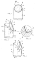
- FIG. 1 A first embodiment of the invention is illustrated by Figures 1 to 3 of the accompanying drawings.
- a cutting component for a drill bit comprising an elongate pin 10 of right-circular cylindrical shape.
- a disc-shaped composite compact 12 comprising a cemented carbide support 14 and an abrasive compact 16.
- the opposite side of the pin has formed therein a longitudinal groove 18. The groove assists in the location of the pin in the drill bit and for the - removal of gasses; when brazing is used.
- the composite compact is located in a recess 20.
- the recess 20 has a base wall 22 and a side wall 24.
- the recess is formed in the pin to one side of longitudinal plane 26 which passes through the central axis of the pin.
- the base wall 22 of the recess slopes from the end surface 28 towards side surface 30. This location of the recess, as mentioned above, is of importance in order to give the composite compact substantial rear support. This rear support is provided by the substantial volume of pin to the left hand side of longitudinal plane 26.
- the composite compact is located in the recess such that the base of the carbide support 14 is supported by the base wall 22 and the side walls 32 of the carbide support are partially supported by the side walls 24 of the recess.
- the side walls 24, when viewed in plan, define an arc.
- the top edge 34 provides the cutting edge.
- the base wall 22 joins the side wall 24 of the recess along line or corner 36.
- This corner receives the lower edge of the carbide support, as can better be seen from Figure 3. Referring to Figure 3, it will be seen that the corner 36 has a radius whereas the tower edge 38 of the carbide support is chamfered. This arrangement produces a non-matching fit between the carbide edge 38 and the corner 36 and thereby avoids direct point contact.
- braze alloy 40 can be accommodated between the two components in this region.
- a radius of 0,3 mm and a chamfer having a vertical height of 0,5 mm and an angle of 45° provides a particularly strong and fracture-resistant tool component.
- the top edges of the pin are cut away at 40 and 42.
Abstract
A tool component comprising a composite compact (12) located in a sloping recess in one end of a solid, elongate right-circular cylindrical pin (10) and bonded thereto. The recess is characterised in that it is formed in the pin to one side of a longitudinal plane (26) passing through the central axis of the pin and the base wall (22) of the recess slopes from one end surface (28) towards a side surface (30). Bonding of the composite compact to the pin is preferably achieved by means of a braze alloy having a working temperature of less than 700°C and containing silver, copper, zinc, manganese and nickel. The tool component has particular application as a cutting component for a drill bit.
Description
- This invention relates to tool components and more particularly to cutting components for drill bits.
- Abrasive compacts are well known in the art and are used for a variety of abrading operations such as cutting, drilling, grinding and the like. Abrasive compacts consist of a polycrystalline mass of bonded abrasive particles, the abrasive particle content of which is at least 70 percent by volume and generally 80 to 90 percent by volume. The abrasive particles may be self-bonded without the aid or use of a second or bonding phase. Alternatively, a second or bonding phase may be provided. The abrasive particles for compacts are invariably diamond or cubic boron nitride.
- Abrasive compacts may be bonded to cemented carbide supports. Such bonded compacts are often referred to as composite compacts. Bonding between the compact and the carbide support may be direct but without the interposition of a braze layer. Alternatively, a bonding braze layer may be provided between the compact and the carbide support.
- A more detailed description of abrasive compacts and composite compacts may be found in a number of published patent specifications, for example United States Patents 3,743,489, 3,767,371, 41063,909 and 3,745,623.
- Rotary drills used for oil and gas well drilling and core drilling generally comprise a drill bit having formed thereon a plurality of preformed sockets in which cutting elements or components are mounted. The cutting elements or components may be brazed, force fitted or heat shrunk into the sockets. Typical cutting elements used in the prior art are steel teeth, steel teeth laminated with tungsten carbide, inserts of cemented tungsten carbide and natural-diamonds.
- Cutting components for drill bits and utilising composite compacts have also been described in the literature and have been used commercially. Such cutting elements comprise an elongate pin of cemented carbide to which is bonded a composite compact, bonding being achieved through the carbide support of the composite compact. Bonding between the carbide support and the elongate pin is achieved by a braze metal which has a melting point above 700°C. Such a high temperature braze, so the art teaches, is essential in order to achieve a sufficiently strong bond between the composite compact and the elongate pin. Reference in this regard may be had to the disclosures of United States Patent No. 4,225,322.
- It has also been proposed to produce a cutting component utilising composite compacts by forming a pocket or recess in an elongate pin to accommodate the composite compact. The composite compact is located in the pocket or recess and then brazed thereto using a braze such as Easy Flo 45 braze. Reference in this regard may be had to the article "Design, Fabrication and Field Test Performance of Slug-type Diamond Compacts Oil Bits" by N.H. Daniels and D.A. Thompson, Journal of Energy Resources Technology, March 1979, Vol. 101 pages 41 to 45. To the best of the Applicant's knowledge, such cutting components have never been used commercially. It is believed that one of the reasons why such cutting components have not been used commercially is that a stress concentration caused by the pocket apparently makes the carbide mounting pin a weaker link. Fracture of the pin through the pocket zone occurs.
- According to the present invention there is provided a tool component comprising:
- a) a composite compact comprising an abrasive compact bonded to a cemented carbide support;
- b) a solid, elongate cylindrical pin having end surfaces joined by side surfaces;
- c) a recess formed in the pin and comprising a base wall and side walls; and
- d) the composite compact being located in the recess such that the carbide support is received by the recess and bonded to the walls thereof. and the abrasive compact presents a cutting edge, characterised in that:
-
- Figure 1 illustrates a front view of a tool component of the invention;
- Figure 2 illustrates a side view of the embodiment of Figure 1;
- Figure 3 illustrates an enlarged sectional view of the ringed area of Figure 2; and
- Figure 4 illustrates a side view of a second embodiment of the invention. I
- As mentioned above, the tool component of the invention is characterised by the recess being formed to one side of a longitudinal plane passing through the central axis of the pin and the base wall slopes from the one end surface to a side surface. This location of the recess to one side of the pin has been found to be of importance because the composite compact is provided thereby with substantial carbide backing support and strength. The top end of the sloping base wall will typically start at the central axis of the pin.
- Bonding of the carbide support to the elongate pin may be achieved by means of a suitable braze alloy. In particular, a braze alloy having a working temperature of less than 700°C and containing silver, copper, zinc, manganese and nickel has been found to be particularly suitable. Braze alloys have a melting range and by "working temperature" is meant the temperature at which melting will take place under ambient conditions to allow a braze joint to be formed. The use of a braze alloy having a working temperature of less than 700°C means that the risk of damage to the abrasive particles of the compact occurring during brazing is minimised. Moreover, it makes for simpler manufacturing conditions and apparatus. The preferred braze alloy contains 49 percent silver, l6.percent copper, 23 percent zinc, 7,5 percent manganese, 4,5 percent nickel, all percentages being by weight. Examples of such alloys are Degussa 4900 and Argo-braze 49.
- The base wall of the recess will preferably slope at an angle of 17 to 25°, typically 20°, to the longitudinal plane.
- The base walls and side walls of the recess meet at a corner or line. To provide maximum strength and to minimise fracture taking place in the pin during use, it has been found that the corner should have a radius and the edge of the carbide support which is received by this corner should have a larger radius than that of the corner or be chamfered. In both cases, direct point contact is avoided and space is provided between the compact and the pin to receive the braze alloys This may explain why fracture problems are avoided.
- The side walls of the recess may be circular when viewed in plan or form an arc.
- The composite compact may be any known in the art and as described in any one of the United States patents described above. The compact for the composite compact will in general be a diamond compact. The most usual shape of the composite compact is a disc.
- The solid, elongate cylindrical pin will generally be made of a cemented carbide such as cemented tungsten carbide.
- The elongate pin will generally have a right-circular cylindrical shape.
- As is known in the art, the surfaces of the pin immediately behind the composite compact may be cut away to provide sufficient clearance in use.
- The tool component of the invention has particular application as a cutting element or component for a drill bit. The component may be secured in a preformed hole in a drill bit by brazing, force fitting or heat shrinking in the conventional manner.
- A first embodiment of the invention is illustrated by Figures 1 to 3 of the accompanying drawings. Referring to Figures 1 and 2, there is shown a cutting component for a drill bit comprising an
elongate pin 10 of right-circular cylindrical shape. To one side of the pin there is bonded a disc-shaped composite compact 12 comprising a cementedcarbide support 14 and an abrasive compact 16. The opposite side of the pin has formed therein alongitudinal groove 18. The groove assists in the location of the pin in the drill bit and for the - removal of gasses; when brazing is used. - The composite compact is located in a
recess 20. Therecess 20 has abase wall 22 and aside wall 24. The recess is formed in the pin to one side oflongitudinal plane 26 which passes through the central axis of the pin. - The
base wall 22 of the recess slopes from theend surface 28 towardsside surface 30. This location of the recess, as mentioned above, is of importance in order to give the composite compact substantial rear support. This rear support is provided by the substantial volume of pin to the left hand side oflongitudinal plane 26. - The composite compact is located in the recess such that the base of the
carbide support 14 is supported by thebase wall 22 and theside walls 32 of the carbide support are partially supported by theside walls 24 of the recess. Theside walls 24, when viewed in plan, define an arc. In use, thetop edge 34 provides the cutting edge. Thebase wall 22 joins theside wall 24 of the recess along line orcorner 36. This corner receives the lower edge of the carbide support, as can better be seen from Figure 3. Referring to Figure 3, it will be seen that thecorner 36 has a radius whereas thetower edge 38 of the carbide support is chamfered. This arrangement produces a non-matching fit between thecarbide edge 38 and thecorner 36 and thereby avoids direct point contact. This, it has been found, is of importance in minimising fracture of the pin during use of the component. Moreover, brazealloy 40 can be accommodated between the two components in this region. By way of example, it has been found that for a composite compact of disc shape, as illustrated, and having a diameter of 13,44 mm and a depth of 5,0 mm, a radius of 0,3 mm and a chamfer having a vertical height of 0,5 mm and an angle of 45° provides a particularly strong and fracture-resistant tool component. - The top edges of the pin are cut away at 40 and 42.
- The embodiment. of Figure 4 is similar to that of Figures 1 to 3 and like parts carry like numerals. The difference in this embodiment is that the
side walls 24 of the recess surround the carbide support completely, and are therefore circular in plan.
the recess is formed in the pin on one side of a longitudinal plane passing through the central axis of the pin and the base wall thereof slopes from one end surface towards a side surface.
Claims (12)
1. A tool component comprising:
the recess is formed in the pin on one side of a longitudinal plane passing through the central axis of the pin and the base wall thereof slopes from one end surface towards a side surface.
a) a composite compact comprising an abrasive compact bonded to a cemented carbide support;
b) a solid, elongate cylindrical pin having end surfaces joined by side surfaces;
c) a recess formed in the pin and comprising a base wall and side walls; and
d) the composite compact being located in the recess such that the carbide support is received by the recess and bonded to the walls thereof and the abrasive compact presents a cutting edge, characterised in that:
the recess is formed in the pin on one side of a longitudinal plane passing through the central axis of the pin and the base wall thereof slopes from one end surface towards a side surface.
2. A tool component according to claim 1 wherein the bonding of the support to the walls of the recess is achieved by a braze alloy having a working temperature of less than 700°C and containing silver, copper, zinc, manganese and nickel.
3. A tool component according to claim 2 wherein the braze alloy contains 49 percent silver, 16 percent copper, 23 percent zinc, 7,5 percent manganese and 4,5 percent nickel, all percentages being by weight.
4. A tool component according to any one of the preceding claims wherein the base wall of the recess slopes at an angle of 17 to 25° to the longitudinal plane.
5. A tool component according to claim 4 wherein the angle is 20°.
6. A tool component according to any one of the preceding claims wherein the base wall of the recess is joined to the side wall by a corner having a radius and a chamfered corner of the carbide support is received by the radiused corner of the recess.
7. A tool component according to any one of claims 1 to 5 wherein the base wall of the recess is joined to the side wall by a corner having a radius and a corner of the carbide support, having a radius larger than that of the corner, is received by this corner.
8. A tool component according to any one of the preceding claims wherein the side walls completely surround the carbide support and are circular in plan.
9. A tool component according to any one of the preceding claims wherein the side walls partially surround the carbide support and are arc- shaped in plan.
10. A tool component according to any one of the preceding claims wherein the compact for the composite compact is a diamond compact.
11. A tool component according to any one of the preceding claims wherein the pin is made of cemented carbide.
12. A tool component according to any one of the preceding claims wherein the pin has a right circular cylindrical shape.
Applications Claiming Priority (2)
| Application Number | Priority Date | Filing Date | Title |
|---|---|---|---|
| ZA827030 | 1982-09-24 | ||
| ZA827030 | 1982-09-24 |
Publications (2)
| Publication Number | Publication Date |
|---|---|
| EP0104894A2 true EP0104894A2 (en) | 1984-04-04 |
| EP0104894A3 EP0104894A3 (en) | 1985-07-31 |
Family
ID=25576289
Family Applications (2)
| Application Number | Title | Priority Date | Filing Date |
|---|---|---|---|
| EP83305631A Withdrawn EP0104894A3 (en) | 1982-09-24 | 1983-09-22 | Tool components |
| EP83305630A Expired EP0104893B1 (en) | 1982-09-24 | 1983-09-22 | Tool component |
Family Applications After (1)
| Application Number | Title | Priority Date | Filing Date |
|---|---|---|---|
| EP83305630A Expired EP0104893B1 (en) | 1982-09-24 | 1983-09-22 | Tool component |
Country Status (5)
| Country | Link |
|---|---|
| US (1) | US4520881A (en) |
| EP (2) | EP0104894A3 (en) |
| JP (2) | JPS59134609A (en) |
| AT (1) | ATE33953T1 (en) |
| DE (1) | DE3376471D1 (en) |
Families Citing this family (23)
| Publication number | Priority date | Publication date | Assignee | Title |
|---|---|---|---|---|
| US4595067A (en) * | 1984-01-17 | 1986-06-17 | Reed Tool Company | Rotary drill bit, parts therefor, and method of manufacturing thereof |
| DE3500931A1 (en) * | 1984-01-31 | 1985-08-08 | De Beers Industrial Diamond Division (Proprietary) Ltd., Johannesburg, Transvaal | CUTTING TOOL |
| AU576032B2 (en) * | 1984-12-06 | 1988-08-11 | De Beers Industrial Diamond Division (Proprietary) Limited | Brazing |
| EP0283605A1 (en) * | 1987-03-24 | 1988-09-28 | Anderson Strathclyde Plc | Cutter tool tip inserts |
| US4797138A (en) * | 1986-02-18 | 1989-01-10 | General Electric Company | Polycrystalline diamond and CBN cutting tools |
| US4690691A (en) * | 1986-02-18 | 1987-09-01 | General Electric Company | Polycrystalline diamond and CBN cutting tools |
| US4702649A (en) * | 1986-02-27 | 1987-10-27 | General Electric Company | Polycrystalline diamond and CBN cutting tools |
| US4714385A (en) * | 1986-02-27 | 1987-12-22 | General Electric Company | Polycrystalline diamond and CBN cutting tools |
| US4767050A (en) * | 1986-03-24 | 1988-08-30 | General Electric Company | Pocketed stud for polycrystalline diamond cutting blanks and method of making same |
| GB8612012D0 (en) * | 1986-05-16 | 1986-06-25 | Nl Petroleum Prod | Rotary drill bits |
| AU604462B2 (en) * | 1986-07-28 | 1990-12-20 | Furukawa Electric Co. Ltd., The | Fin of heat exchanger and method of making it |
| EP0263660B1 (en) * | 1986-10-06 | 1996-01-10 | De Beers Industrial Diamond Division (Proprietary) Limited | Cutting component |
| US4727945A (en) * | 1986-12-29 | 1988-03-01 | Strata Bit Corporation | Cutting element having diamond cutting blank reinforced by a shoulder |
| JPH0431348Y2 (en) * | 1987-07-24 | 1992-07-28 | ||
| GB2216929B (en) * | 1988-04-05 | 1992-11-04 | Reed Tool Co | Improvements in or relating to cutting elements for rotary drill bits |
| GB8901729D0 (en) * | 1989-01-26 | 1989-03-15 | Reed Tool Co | Improvements in or relating to cutter assemblies for rotary drill bits |
| JP2527621Y2 (en) * | 1990-06-29 | 1997-03-05 | 東邦金属株式会社 | Lock bit |
| US20040155096A1 (en) * | 2003-02-07 | 2004-08-12 | General Electric Company | Diamond tool inserts pre-fixed with braze alloys and methods to manufacture thereof |
| JP4858940B2 (en) * | 2005-03-25 | 2012-01-18 | 三菱マテリアル株式会社 | Drilling bit and cutting edge insert |
| RU2008137529A (en) * | 2006-02-23 | 2010-03-27 | Бейкер Хьюз Инкорпорейтед (Us) | INSERT FOR ATTACHING THE AUXILIARY CUTTING ELEMENT OF A ROTARY DRILLING BIT |
| US8881850B2 (en) * | 2009-05-01 | 2014-11-11 | Smith International, Inc. | Cutter pocket design |
| US10381322B1 (en) | 2018-04-23 | 2019-08-13 | Sandisk Technologies Llc | Three-dimensional memory device containing self-aligned interlocking bonded structure and method of making the same |
| US10879260B2 (en) | 2019-02-28 | 2020-12-29 | Sandisk Technologies Llc | Bonded assembly of a support die and plural memory dies containing laterally shifted vertical interconnections and methods for making the same |
Citations (7)
| Publication number | Priority date | Publication date | Assignee | Title |
|---|---|---|---|---|
| US3745623A (en) * | 1971-12-27 | 1973-07-17 | Gen Electric | Diamond tools for machining |
| US3970158A (en) * | 1975-04-28 | 1976-07-20 | Hughes Tool Company | Tooth loading for earth boring bits |
| US4073354A (en) * | 1976-11-26 | 1978-02-14 | Christensen, Inc. | Earth-boring drill bits |
| US4156329A (en) * | 1977-05-13 | 1979-05-29 | General Electric Company | Method for fabricating a rotary drill bit and composite compact cutters therefor |
| US4225322A (en) * | 1978-01-10 | 1980-09-30 | General Electric Company | Composite compact components fabricated with high temperature brazing filler metal and method for making same |
| US4244432A (en) * | 1978-06-08 | 1981-01-13 | Christensen, Inc. | Earth-boring drill bits |
| US4350215A (en) * | 1978-09-18 | 1982-09-21 | Nl Industries Inc. | Drill bit and method of manufacture |
Family Cites Families (7)
| Publication number | Priority date | Publication date | Assignee | Title |
|---|---|---|---|---|
| GB410947A (en) * | 1932-07-28 | 1934-05-31 | Charles Erickson | Improvements in rock drills |
| GB1532840A (en) * | 1976-09-24 | 1978-11-22 | Sheffield Smelting Co Ltd | Brazing alloys |
| US4289211A (en) * | 1977-03-03 | 1981-09-15 | Sandvik Aktiebolag | Rock drill bit |
| ZA781154B (en) * | 1978-02-28 | 1979-09-26 | De Beers Ind Diamond | Abrasive bodies |
| US4221270A (en) * | 1978-12-18 | 1980-09-09 | Smith International, Inc. | Drag bit |
| US4303136A (en) * | 1979-05-04 | 1981-12-01 | Smith International, Inc. | Fluid passage formed by diamond insert studs for drag bits |
| JPS563790A (en) * | 1979-06-19 | 1981-01-16 | Toho Kinzoku Kk | Rock bit |
-
1983
- 1983-09-21 US US06/534,195 patent/US4520881A/en not_active Expired - Fee Related
- 1983-09-22 EP EP83305631A patent/EP0104894A3/en not_active Withdrawn
- 1983-09-22 DE DE8383305630T patent/DE3376471D1/en not_active Expired
- 1983-09-22 JP JP58176177A patent/JPS59134609A/en active Granted
- 1983-09-22 AT AT83305630T patent/ATE33953T1/en not_active IP Right Cessation
- 1983-09-22 JP JP58176178A patent/JPS59130996A/en active Pending
- 1983-09-22 EP EP83305630A patent/EP0104893B1/en not_active Expired
Patent Citations (7)
| Publication number | Priority date | Publication date | Assignee | Title |
|---|---|---|---|---|
| US3745623A (en) * | 1971-12-27 | 1973-07-17 | Gen Electric | Diamond tools for machining |
| US3970158A (en) * | 1975-04-28 | 1976-07-20 | Hughes Tool Company | Tooth loading for earth boring bits |
| US4073354A (en) * | 1976-11-26 | 1978-02-14 | Christensen, Inc. | Earth-boring drill bits |
| US4156329A (en) * | 1977-05-13 | 1979-05-29 | General Electric Company | Method for fabricating a rotary drill bit and composite compact cutters therefor |
| US4225322A (en) * | 1978-01-10 | 1980-09-30 | General Electric Company | Composite compact components fabricated with high temperature brazing filler metal and method for making same |
| US4244432A (en) * | 1978-06-08 | 1981-01-13 | Christensen, Inc. | Earth-boring drill bits |
| US4350215A (en) * | 1978-09-18 | 1982-09-21 | Nl Industries Inc. | Drill bit and method of manufacture |
Non-Patent Citations (1)
| Title |
|---|
| JOURNAL OF ENERGY RESOURCES TECHNOLOGY, vol. 101, March 1979; DANIELS et al. "Design, fabrication and field testperformance of slug-type diamond compacts oil bits", pages 41-45 * |
Also Published As
| Publication number | Publication date |
|---|---|
| JPS59130996A (en) | 1984-07-27 |
| JPS59134609A (en) | 1984-08-02 |
| EP0104893A2 (en) | 1984-04-04 |
| EP0104894A3 (en) | 1985-07-31 |
| US4520881A (en) | 1985-06-04 |
| JPH0253597B2 (en) | 1990-11-19 |
| ATE33953T1 (en) | 1988-05-15 |
| EP0104893A3 (en) | 1985-08-07 |
| EP0104893B1 (en) | 1988-05-04 |
| DE3376471D1 (en) | 1988-06-09 |
Similar Documents
| Publication | Publication Date | Title |
|---|---|---|
| US4520881A (en) | Tool component | |
| US4655508A (en) | Tool component | |
| EP0238938B1 (en) | Pocketed stud for polycrystalline diamond cutting blanks | |
| EP0353214B1 (en) | Drill bit with cemented carbide inserts | |
| US4359112A (en) | Hybrid diamond insert platform locator and retention method | |
| US5533582A (en) | Drill bit cutting element | |
| JP2934927B2 (en) | Diamond rotary cutter | |
| US4529048A (en) | Inserts having two components anchored together at a non-perpendicular angle of attachment for use in rotary type drag bits | |
| EP0741228A2 (en) | Improvement in or relating to cutting element for rotary drill bits | |
| EP1201873B1 (en) | PDC bit with stress relief groove | |
| US5193948A (en) | Chip control inserts with diamond segments | |
| KR20070034109A (en) | Indexable cutting inserts and manufacturing method thereof | |
| EP0236086B1 (en) | An insert for a tool | |
| AU1937000A (en) | Rotatable cutting bit assembly with cutting inserts | |
| EP0263660B1 (en) | Cutting component | |
| GB2084219A (en) | Mounting of cutters on cutting tools | |
| US4941891A (en) | Tool component | |
| US6527633B1 (en) | Abrasive body | |
| EP0138392A1 (en) | Cutting tool | |
| US4941892A (en) | Tool component | |
| GB2300437A (en) | Cutting elements for rotary drill bits | |
| JPH08168905A (en) | Cutting tool | |
| JPH09201705A (en) | Center | |
| Araki et al. | High Hardness Cutting Tool |
Legal Events
| Date | Code | Title | Description |
|---|---|---|---|
| PUAI | Public reference made under article 153(3) epc to a published international application that has entered the european phase |
Free format text: ORIGINAL CODE: 0009012 |
|
| AK | Designated contracting states |
Designated state(s): AT CH DE FR GB LI SE |
|
| PUAL | Search report despatched |
Free format text: ORIGINAL CODE: 0009013 |
|
| AK | Designated contracting states |
Designated state(s): AT CH DE FR GB LI SE |
|
| 17P | Request for examination filed |
Effective date: 19850805 |
|
| 17Q | First examination report despatched |
Effective date: 19860604 |
|
| D17Q | First examination report despatched (deleted) | ||
| STAA | Information on the status of an ep patent application or granted ep patent |
Free format text: STATUS: THE APPLICATION IS DEEMED TO BE WITHDRAWN |
|
| 18D | Application deemed to be withdrawn |
Effective date: 19870825 |
|
| RIN1 | Information on inventor provided before grant (corrected) |
Inventor name: PHAAL, CORNELIUS |