EP0100977A2 - Endoscope - Google Patents
Endoscope Download PDFInfo
- Publication number
- EP0100977A2 EP0100977A2 EP83107511A EP83107511A EP0100977A2 EP 0100977 A2 EP0100977 A2 EP 0100977A2 EP 83107511 A EP83107511 A EP 83107511A EP 83107511 A EP83107511 A EP 83107511A EP 0100977 A2 EP0100977 A2 EP 0100977A2
- Authority
- EP
- European Patent Office
- Prior art keywords
- main body
- casing
- operation section
- gripping cover
- casing body
- Prior art date
- Legal status (The legal status is an assumption and is not a legal conclusion. Google has not performed a legal analysis and makes no representation as to the accuracy of the status listed.)
- Granted
Links
- 238000003825 pressing Methods 0.000 claims abstract description 8
- 230000002093 peripheral effect Effects 0.000 claims description 22
- 238000007789 sealing Methods 0.000 claims description 8
- 238000012856 packing Methods 0.000 claims description 4
- 239000000057 synthetic resin Substances 0.000 claims description 3
- 229920003002 synthetic resin Polymers 0.000 claims description 3
- 238000005452 bending Methods 0.000 description 48
- 239000002184 metal Substances 0.000 description 19
- 230000003449 preventive effect Effects 0.000 description 14
- 238000007906 compression Methods 0.000 description 12
- 230000006835 compression Effects 0.000 description 12
- 238000003780 insertion Methods 0.000 description 12
- 230000037431 insertion Effects 0.000 description 12
- 238000005304 joining Methods 0.000 description 9
- 238000000638 solvent extraction Methods 0.000 description 6
- 230000001105 regulatory effect Effects 0.000 description 5
- 230000008878 coupling Effects 0.000 description 4
- 238000010168 coupling process Methods 0.000 description 4
- 238000005859 coupling reaction Methods 0.000 description 4
- XLYOFNOQVPJJNP-UHFFFAOYSA-N water Substances O XLYOFNOQVPJJNP-UHFFFAOYSA-N 0.000 description 3
- 238000005219 brazing Methods 0.000 description 2
- 238000006243 chemical reaction Methods 0.000 description 2
- 238000009826 distribution Methods 0.000 description 2
- 230000000694 effects Effects 0.000 description 2
- 238000004519 manufacturing process Methods 0.000 description 2
- 238000000034 method Methods 0.000 description 2
- 230000002265 prevention Effects 0.000 description 2
- 239000012260 resinous material Substances 0.000 description 2
- 238000005299 abrasion Methods 0.000 description 1
- 230000001154 acute effect Effects 0.000 description 1
- 238000010276 construction Methods 0.000 description 1
- 230000003247 decreasing effect Effects 0.000 description 1
- 239000000835 fiber Substances 0.000 description 1
- 239000012530 fluid Substances 0.000 description 1
- 239000000463 material Substances 0.000 description 1
- 238000000465 moulding Methods 0.000 description 1
- 230000008092 positive effect Effects 0.000 description 1
- 239000012858 resilient material Substances 0.000 description 1
- 230000000630 rising effect Effects 0.000 description 1
- 230000006641 stabilisation Effects 0.000 description 1
- 238000011105 stabilization Methods 0.000 description 1
- 238000004804 winding Methods 0.000 description 1
Images


Classifications
-
- A—HUMAN NECESSITIES
- A61—MEDICAL OR VETERINARY SCIENCE; HYGIENE
- A61B—DIAGNOSIS; SURGERY; IDENTIFICATION
- A61B1/00—Instruments for performing medical examinations of the interior of cavities or tubes of the body by visual or photographical inspection, e.g. endoscopes; Illuminating arrangements therefor
- A61B1/00131—Accessories for endoscopes
- A61B1/00137—End pieces at either end of the endoscope, e.g. caps, seals or forceps plugs
-
- A—HUMAN NECESSITIES
- A61—MEDICAL OR VETERINARY SCIENCE; HYGIENE
- A61B—DIAGNOSIS; SURGERY; IDENTIFICATION
- A61B1/00—Instruments for performing medical examinations of the interior of cavities or tubes of the body by visual or photographical inspection, e.g. endoscopes; Illuminating arrangements therefor
- A61B1/005—Flexible endoscopes
- A61B1/0051—Flexible endoscopes with controlled bending of insertion part
- A61B1/0052—Constructional details of control elements, e.g. handles
-
- G—PHYSICS
- G02—OPTICS
- G02B—OPTICAL ELEMENTS, SYSTEMS OR APPARATUS
- G02B23/00—Telescopes, e.g. binoculars; Periscopes; Instruments for viewing the inside of hollow bodies; Viewfinders; Optical aiming or sighting devices
- G02B23/24—Instruments or systems for viewing the inside of hollow bodies, e.g. fibrescopes
- G02B23/2476—Non-optical details, e.g. housings, mountings, supports
Definitions
- the present invention relates to an endoscope having an operation section which has been structurally improved, thereby facilitating assembly of the endoscope.
- the operation section of a prior art endoscope is assembled in such a way that, as shown in Fig. 1, a pair of covering members b are screwed and fastened by means of, e.g., setscrews, to a base'member a serving as a main body of said operation section, from the right and left sides thereof, respectively.
- the base member a is designed to have sufficient mechanical strength and the covering members b'are intended to function only as a casing attached to the base member a.
- the base member a within the operation section has disposed therearound a plurality of built-in members c, such as a bending operation wire, a treating instrument inductor raising wire, an air/water intake tube, various channels, an electrical wire distribution, etc.
- built-in members c such as a bending operation wire, a treating instrument inductor raising wire, an air/water intake tube, various channels, an electrical wire distribution, etc.
- the elements extended into the side of the endoscope whose base member has an insertion portion must be connected to the elements extended from the side of an ocular portion or from the side of a connector portion connected to accessory devices. For this reason, it is impossible to construct the base member a in such a way that its structure may entail a large section modulus to house the built-in members.
- a structure such as that shown in Fig. 1, having a sectional configuration shaped like the letter I, may be adopted for the base member.
- a primary object of the present invention is to provide an endoscope with a structure having sufficient mechanical strength, while satisfying the requirement that the operation section be light and small, a prerequisite of the operation section of an endoscope operable with one hand over a long period of time.
- Fig. 2 schematically shows an entire endoscope.
- This endoscope is comprised of an insertion section 1, an operation section 2 and a light guide cable section 3.
- the operation section 2 is comprised of a main body 4 as shown in Fig. 3, and a casing 5 (Figs. 2 and 9) consisting of synthetic resin and so arranged as to cover and contain the main body 4.
- the casing 5 is divided into two parts, one of which is a casing body 6 made substantially rectangular and shaped like a hollow box and the other of which is a cylindrical gripping cover 7. Those two parts are joined together in such a manner that their hollow portions are allowed to come into contact with each other.
- the casing body 6 is provided with an ocular portion 8, an air/water feed control element 9, suction control element 11 and a bending operation knob 12 (Fig. 3).
- the reference numeral 10a in Fig. 2 denotes an intermediate coupling portion of an air/water feeding tube while the reference numeral 10b denotes an intermediate coupling portion of a suction tube 54 as later described.
- These intermediate coupling portions 10a and 10b are disposed within the gripping cover 7.
- an inclined face 13 is formed on the portion of the casing body 6 opposite to the portion where the bending operation knob 12 is provided. This inclined face 13 is provided with an opening portion 14 in such a manner that this portion 14 is opposed to the main body 4 of the operation section.
- the opening portion 14 is attached with a casing cover 15, that is, a lid member 15, which consists of synthetic resin in such a manner that the opening is closed by the lid member 15.
- a casing cover 15 that is, a lid member 15, which consists of synthetic resin in such a manner that the opening is closed by the lid member 15.
- This fixing metal fitting 17 is formed or prepared by fabricating, i.e., by pressing a thin metal plate, such as that which has a Japanese Industrial Standard of, e.g., C 1720P, C 5211P, C 2680P, C 2800P, A 5052P, SPCC, SUS 304CP, etc., and is comprised of a top plate portion 18 and three support leg portions 19 made integral with the top plate portion 18 and bent from the same. Further, a bent portion 19a is formed on the lower end portion of each of the three support leg portions 19 and is formed with an attaching hole 19b, through which a fastening screw 20 is idly inserted via a spring washer 20a.
- a thin metal plate such as that which has a Japanese Industrial Standard of, e.g., C 1720P, C 5211P, C 2680P, C 2800P, A 5052P, SPCC, SUS 304CP, etc.
- the fixing metal fitting 17 is attached to the main body 4 of the operation section by means of the fastening screw 20. Accordingly, the top plate portion 18 of the fixing metal fitting 17 and upper portions of the support leg portions 19 are allowed to protrude from the opening portion 14 of the casing body 6. The top plate portion 18 and support leg portions 19 thus protruded are formed with attaching holes 21.
- a base end portion of the light guide cable 3 is comprised of a flexible tube 22 used to have equipped therein elongate members such as a light guide fiber f, a fluid transport pipe t and an electric signal wire !, and a mouthpiece pipe 23 fitted to an end portion of this flexible tube 22.
- a base end portion of the mouthpiece pipe 23 is formed with a notched portion 24, which is formed with screw holes 25 arranged to oppose said attaching holes 21 of the fixing metal fitting 17.
- the fixing metal fitting 17 and the base end portion of the mouthpiece pipe 23 are integrally fixed to each other by screwing into the screw holes 25 the fixing screws 26 passing through the attaching holes 21.
- a break preventive rubber tube 27 onto the base end portion of the flexible tube 22 there is fitted a break preventive rubber tube 27 whose open end has a mouthpiece 28 screwed thereinto and thus joined thereto.
- a base end portion of a fastening ring 29 is screwed into and joined and fixed to this mouthpiece 28.
- the fastening ring 29 is allowed to protrude from the end face of the break preventive rubber tube 27, the protruded portion thereof being formed with a first annular groove 30 on its inner peripheral surface and a second annular groove 31 on its outer peripheral surface.
- the first and second annular grooves 30 and 31 are formed in such a manner that they adjoin to each other in the axial direction of the light guide cable section 3.
- the first and second annular grooves 30 and 31 have received therein resilient seal members 32 and 33 consisting of 0-ring, respectively.
- a stepped portion 34 is provided on the outer peripheral surface of the portion of the fastening ring 29 located between the first and second annular grooves 30 and 31; while, on the other hand, an internally threaded portion 35 is formed on the inner peripheral surface of the fastening ring corresponding to the second annular groove 31.
- This internally threaded portion 35 is screwed onto an externally threaded portion 36 provided on the outer peripheral surface of the mouthpiece pipe 23.
- the base end face of the fastening ring 29 is integrally provided with a fastening annular portion 37 shaped like a wedged in section, in such a way that this portion is engaged with the casing lid member 15.
- the opening portion 14 provided with reference to the inclined face 13 of the casing body 6 is formed in a rectangular shape and is provided, on its inner peripheral edge, with an inclined pressure receiving portion 38.
- the casing lid member 15 is made rectangular, in such a manner that it closes the opening portion 14; and is provided, on its outer peripheral edge, with an inclined pressure application portion 39, which is to be joined to the. inclined pressure receiving portion 38.
- the casing lid member 15 is also formed, along its outer peripheral edge, with a protruded portion 40 at a position inward of the inclined pressing portion 39.
- a resilient seal member 41 consisting of 0-ring which is intended to seal, on a watertight basis, the portion between the outer side of the protruded portion and the inner peripheral surface of the casing body 6.
- a square hollow member 42 which covers the fixing metal fitting 17.
- a tip end portion of the fitting hollow member 42 is provided with a circular fitting portion 43 fitted onto the outer periphery of the fastening ring 29, and an opening end of this fitting portion 43 is formed with a fitting step portion 44 opposing the stepped portion 34 of the fastening ring 29.
- An inner peripheral protrusion portion 45 is provided on a portion, opposing a part of the fastening annular portion 37, of the inner peripheral surface of the fitting square hollow member 42. This inner peripheral protrusion portion 45 is formed with an engaging notched portion 46 which is to be brought into engagement with the fastening annular portion 37.
- the method of connecting, for assembly, the light guide cable 3 to the main body 4 of the operation section fixed to the casing 5 may be described as follows.
- the fixing metal fitting 17 is inserted into the casing body 6 from the opening portion 14 thereof and the support leg portions 19 are fastened and secured to the main body 4 by means of the fixing screws 20.
- the attaching holes 19b of the support leg portions 19 are each made large enough (in diameter) to permit the fixing screw 20 to idly pass therethrough, it is possible to fix the fixing metal fitting 17 to the main body 4 of the operation section on an adjustable basis.
- the base end portion of the mouthpiece pipe 23 provided with reference to the flexible tube 22 of the light guide cable 3 is positioned with respect to the top plate portion 18, whereby the mouthpiece pipe 23 and the fixing metal fitting 17 are integrally attached to each other by means of the fixing screws 26.
- the fixing metal fitting 17 is,formed of a thin metal plate or sheet, the positioning of the mouthpiece pipe 23 can be adjusted by elastically deforming the fixing metal fitting 17.
- the fitting square hollow member 42 of the casing lid member 15 covers the flexible tube 22 of the light guide cable 3. Then, the casing lid member 15 is moved toward the casing body 6; and, while the fixing metal fitting 17 is enclosed by the hollow member 42, the inclined pressing portion 39 of the casing lid member 15 is allowed to abut against the inclined pressure receiving portion 38 of the casing body 6, thereby closing the opening portion 14.
- the fastening ring 29 fitted with the resilient seal members 32 and 33, and the break preventive rubber tube 27 integrally joined thereto cover the flexible tube 22 of the light guide cable 3, thereafter to screw the internally threaded portion 35 onto the externally threaded portion 36 of the mouthpiece pipe 23 of the flexible tube 22, thereby to fasten the fastening ring onto the same.
- the fastening of the fastening ring 29 causes the resilient seal member 33 to exert a force acting in a direction perpendicular to the axis 15a, namely in the direction of arrow A.
- the fastening annular portion 37 of the fastening ring 29 is engaged with the engaging notched portion 46 of the inner peripheral protrusion 45 of the fitting square hollow member 42, the fastening of the fastening ring 29 causes a force acting in the direction indicated by arrow P to be applied to the inner peripheral protrusion 45.
- the casing lid member 15 and the casing body 6 are adhered or bonded to each other by a joining of the inclined pressing portion 39 to the inclined pressure receiving portion 38.
- the resilient seal member 33 has its body biased by the fastening of the fastening ring 29, the sealing between the fastening ring 29 and the casing lid member 15 is ensured, even when such resilient seal member has its body maximally biased to a value great enough to permit the creation of a clearance therebetween.
- the sealing of the fastening ring 29 to the mouthpiece pipe 23 is completely achieved by the resilient seal member 32, on a watertight basis.
- the sealing of the casing body 6 to the casing lid member 15 is accomplished by means of the resilient seal member 41, on a watertight basis.
- the above-mentioned gripping cover 7 has an outer diameter and a length which are suitable for gripping by an examiner using only one hand.
- an attaching hollow portion 48 used to mount a channel mouthpiece 47 thereto as shown in Figs. 7 and 8. That is, the channel mouthpiece 47 is removably inserted from outside and fitted into the attaching hollow portion 48 and is fixed thereto by means of a pair of attaching screws 51, as shown in Fig. 7. Further, as shown in Fig. 8, the channel mouthpiece 47 is connected to one end of a three-way joint 52.
- a channel tube 53 To one of the remaining ends of the three-way tube, there is connected a channel tube 53, and a suction tube 54 is connected to the other of said remaining ends.
- a suction tube 54 This provides the above-mentioned intermediate coupling portion 10b wherein the channel tube 53 and the suction tube 54 are respectively connected to the ends of the three-way joint 52.
- the main body 4 of the operation section disposed within the casing 5 as shown in Fig. 3, is comprised of a plurality of members; or, as in this embodiment; is comprised of a base plate 56 made of metal, a pair of frames 57 and a cylindrical member 58. More specifically, a pair of bent piece portions 59 are provided on an end portion of the metallic base plate 56 located on the side of the insertion section 1. Further, a pair of said frames 57 are screwed and connected, at one end, to the bent piece portions 59, respectively, and, at the other end, to the side surface of the cylindrical member 58.
- the base plate 56 is so disposed as to extend through the casing body 6 and the gripping cover 7.
- the paired frames are disposed within the gripping cover 7, and the cylindrical member 58 is disposed in such a manner as to extend and project from a tip end opening portion of the gripping cover 7.
- the said three-way joint 52 is attached and stabilized by means of setscrews 61, as shown in Fig. 8.
- a base end portion 62 of the flexible tube extending from the insertion section 1 is connected, by means of a check ring 63, to an extended tip end portion of the cylindrical member 58.
- a break preventive member 65 consisting of resilient material having a relatively high rigidity is connected to the cylindrical member 58 through a connecting pipe 64.
- a cylindrical watertight cover 66 is fitted onto the outer periphery of the cylindrical member 58 and is partially allowed to enter the opening end of the gripping cover 7 and is connected thereto on a watertight basis.
- the other end of the watertight cover 66 is joined to an end face of the break preventive member 65.
- Ring-like resilient packings 67 are interposed between the joining portions of the watertight cover 66 and the gripping cover 7, between the joining portions of the watertight cover 66 and the cylindrical member 58 located on the side of the insertion section 1, and between the cylindrical member 58 and a base end portion of the insertion section 1, respectively, so as to ensure the watertightness therebetween.
- a receiving portion.68 is formed, which portion 68 projects toward the central axis thereof, over the entire inner peripheral surface of said opening portion, as shown in Fig. 8.
- a pair of nut-like juxtaposed fastening members 71 are abutted, being screwed onto an external thread 69 formed on the outer peripheral surface of the cylindrical member 58.
- the other end of the main body 4 of the operation section 2, i.e., the end of the base plate 56 located on the side of the ocular portion 8, is attached and fixed, for example, to a side wall 74 of the casing body 6 by means of a pair of members, such as metallic members 72 and 73 as shown in Figs. 3 and 12.
- the side wall 74 is sandwiched between the paired metallic members 72, 73 and -is fastened and fixed therebetween by means of setscrews 75, each passing through these three members, and by mean of nuts 76.
- the inner metallic member 72 has a piece 77 formed. on one side edge thereof, which piece 77 is screwed onto the base plate 56. Further, the parts of the ocular portion 8 are assembled on the outer metallic member 73, as shown in Fig. 12.
- the casing body 6 of the casing 5 and the gripping cover 7 are connected to each other in a manner such as that shown in Fig. 9. That is, the casing body 6 is formed with a projection 79 which projects toward the side of the gripping cover 7 from a joining znd face 78 of the casing body 6 and which has a configuration corresponding to that of the opening portion of the grippint cover 7. Further, said projection 79 is so arranged as to be fitted into the opening end of the gripping cover 7. Further, an inner peripheral surface of the opening end portion of the gripping cover 7 fitted with the projection 79 is made large in diameter correspondingly to the thickness of the projection 79, whereby a step portion 80 is formed.
- a projection portion 80a allowed to project toward the casing body 6 is formed on a tip end of a rising wall surface of this step portion 80 while, on a tip end of the projection 79 as well, a projection portion 79a is so formed as to corresponding to the projection portion 80a.
- the projection portions 79a and 80a are each formed with an inclined surface at the side of the bottom surface of the step portion 80, and a.resilient packing 81 shaped like a ring is fitted into a space portion thus enclosed by those surfaces.
- the base plate 56 of the main body 4 of the operation section has a bending operation mechanism mounted thereon, as-shown in Fig. 9.
- a fixing portion 82a of a shaft 82 provided projecting from the base plate.
- An inner sleeve 83 and an outer sleeve 84 are rotatably fitted onto the shaft 82.
- the sleeves 83, 84 are respectively engaged at one of their side ends with a pair of sprockets 85 (only one of which is shown) disposed at upper and lower positions in the axial direction of the shaft 82, in such a manner as to be rotatable thereabout; and are allowed, at their other side ends, to project from the casing body 6, being respectively connected to the above-mentioned bending operation knobs 12 (only one of which is shown in Fig. 3).
- a partitioning member 86 which U-shaped in cross section is attached and fixed to the base plate 56 (longitudinally thereof) by means of a fixing plate 87, through its intermediate bottom portion.
- a passage 89 is defined by a defining wall 88, in such a manner that the resultant passages 89 are arranged at upper and lower stages, with the partitioning member interposed therebetween.
- the defining wall 88 is divided into two parts, one being an inner defining wall 88a and the other being an outer defining wall 88b, in the widthwise direction of the passage 89.
- the inner and outer defining walls 88a and 88b are supported by and fixed to support portions 90a and 90 erected on the base plate 56, at their midway positions taken in their longitudinal directions and at their ends located on the side of the sprockets 85.
- An attaching plate 91 is erected on the upper surface of the end portion of the partitioning wall member 86 located on the side opposite to that at which the sprockets 85 are disposed.
- a flat-plate like retaining member 92 having a width greater than that of the partitioning wall member 86.
- sets of notches 93 which sets each consist of two notches, are formed correspondingly to the passages 89, respectively.
- a hollow cylindrical regulating member 94 formed with a step portion 94a made smaller in diameter at a midway position taken in the axial direction thereof, in a state wherein the step portion 94a is engaged with the notch 93 in such a manner that this regulating member 94 is thereby prevented from being moved in the axial direction thereof.
- This regulating member 94 is held in place in such a manner that the disengagement thereof from the notch 93 is prevented by the abutment of an end portion of the outer defining wall member 88b against the peripheral surface of the regulating member 94.
- a base end portion consisting of a flexible wire guide pipe 95 comprised of a coil of a close winding or the like is inserted into the insertion section 1 throughout the entire length thereof, whereby said base end portion is fixed by brazing to the regulating member 94, by the use of a brazing material member 96a.
- a wire 96 is inserted through the wire guide pipe 95. This wire is connected and fixed at its tip end to a top (not shown) constituting the bending portion, and is lead into the passage 89 at its base end side.
- a connecting member 97 is connected to the base end of the wire 96 guided into and through the passage 89.
- An end portion of a chain 98 engaged at its midway position with the above-mentioned.sprocket 85 is connected to the connecting member 97. Further, on the connecting member 97, there is planted or provided an abutment member 99 in such a manner that the member 99 intersects the axial line of the wire 96 at right angles thereto. A part of this abutment member 99 is allowed to project toward an outside of the base plate 56 taken in the widthwise direction thereof. The outer peripheral surface of this projected portion of the abutment member is formed into an inclined surface 100 defining an acute angle with an end face thereof.
- a wall portion 101 formed by bending a part of the base plate 56 or a separate member into the shape of the letter U-shape' is provided between the first and second support portions 90a, 90 erected on the base plate 56.
- a support hole 102 is formed in one way portion of this wall portion 101 located along the widthwise direction of the base plate 56.
- the screw 103 is provided in such a manner that its axial line is made parallel to the axial line of the wire 96 and is located at a position, on the outside of the base plate 56 taken in the widthwise direction thereof, which is more outward of this plate than the axial line of the wire 96.
- a terminal end of the threaded portion 103a is engaged with a support hole 104 formed in the second support portion 90.
- a stopper 105 is screwed onto the threaded portion 103a of the screw 103 and has a height slightly lower than the height of the passage 89.
- the upper surface of the stopper 105 is allowed to abut against an upper wall surface of the passage 89 and is thereby prevented from being rotated in such a way as to be moved forwards and backwards through the passage 89.
- the passage 89 corresponding to a portion wherein the screw 103 is provided is defined by the above-mentioned defining wall 88b.
- an inclined surface 106 having an angle of inclination corresponding to the inclined surface 100 of the abutment member 99 is formed.
- the travel of the wire 96 i.e., the maximum bending angle of the bending portion defined in the rightward and leftward directions, as well as in the upward and downward directions, is limited.
- the head portion 103b of the screw 103 is formed with an engaging bore 107 allowed to pass therethrough, in the radial direction thereof.
- An engaging stopper spring 108 prepared by bending a wire into a waveform configuration is engaged at one end with said engaging bore 107. Further, the engaging stopper spring 108 is pressed at the other end against the first support portion 90a in a state wherein it is kept compressed.
- the screw 103 is prevented by the engaging stopper spring 108 from being rotated about its axis, and an end face of the head portion 103b is pressed due to the restoring force of the engaging stopper spring 108 against a side face of the wall portion 101, whereby the head portion 103b is prevented from being moved in a direction in which it is escaped from, or spaced away from, the support hole 102.
- the maximum bending angle of the bending portion is defined by the stopper 105. Further, when the abutment member 99 is allowed to abut against the stopper 105, the screw 103 is pressed onto the side face of the second support portion 90 through the stopper 105. At this time, however; in this screw 103, the end face of the head portion 103b thereof is allowed to abut against the side face of the wall portion 101, whereby the screw 103 is prevented from being axially moved, along with the stopper 105. As a result, the possibility that the maximum bending angle of the bending portion would become greater than an initial preset angle may be eliminated.
- the engaging stopper spring 108 provided, in a state wherein it is compressed, between the first support portion 90a and the engaging bore 107 of the head portion 103b of the screw 103 is dismounted by being further compressed.
- the screw 103 is rotated, whereby the stopper 105 is displaced toward the second support portion 90.
- the bending portion is bent until it has a predetermined bending angle, by rotation of the bending operation knob 12.
- the screw 103 is rotated in the opposite direction to that in which the preceding rotation thereof was made, until the inclined surface 106 of the stopper 105 abuts against the inclined surface 100 of the abutment member 99.
- the engaging stopper spring 108 is again mounted between the first support portion 90a and the engaging bore 107 of the head portion 103b of the screw 103, whereby the stopper 105 is fixed to a predetermined position through the screw 103.
- the maximum bending angle of the bending portion is set by the stopper 105.
- flexure preventive stopper members 111, 112 are mounted upon protruded tip ends of the support portions 90, respectively, as shown in Figs. 11 and 13.
- the flexure preventive stopper members lll, 112 are each made of a synthetic resinous material and are mounted in such a manner that their external threaded portions formed on their one-side end portions are screwed into the threaded bores 104 formed in the support portions 90.
- the other side ends of these flexure preventive stopper members 111, 112 are allowed to abut against the inner wall surface of the casing 5; or, in this case, against the inner wall surface of the casing body 6. As shown in Fig.
- a stopper piece 113 serving as a separate flexure preventive stopper member is screwed and fixed to the base plate 56 at a position thereof which is opposite to that at which the flexure preventive stopper members 111, 112 are fixed thereto. As shown in Fig. 13, this stopper piece 113 abuts against the inner wall surface (i.e., the inner wall surface opposite to that against which the flexure preventive stopper members 111, 112 abut) of the casing body 6. It should be noted here that, preferably, the flexure preventive stopper members 111, 112 and the stopper piece 113 are disposed substantially on flat planes intersecting the surface of the base plate 56 at right angles thereto, as shown in Fig. 13.
- the flexure preventive stopper members lll, 112 and the stopper piece 113 are provided on the sides of the main body 4 of the operation section at which the same is flexed and swollen, for example, at the time of the bending operation, in such a manner that they are allowed at all times to abut against the inner wall surfaces of the casing body 6, the main body 4, especially the base plate 56, is prevented from being flexed at the time of, for example, the bending operation, even when it tends to be flexed.
- the flexure preventive stopper members 111, 112 and the'stopper piece 113 are not required to be kept in constant abutment against the inner wall of the casing body 6 in a state wherein they are cohered to this inner wall, but may be spaced therefrom to such an extent that, when the main body 4 has been flexed slightly, they may abut against said inner wall.
- the assembling structure of the operation section 2 is so disposed that the hollow box casing body 6 and the cylindrical gripping cover 7 are joined together to form the cylindrical casing 5 as a whole; the main body 4 is inserted and disposed within said casing 5; and the ends of the casing 5 are supported by the main body 4 of the operation section, in such a manner as to afford a pulling force to pull the main body 4.
- the end of the main body 4 of the operation section 2 located on the side of the ocular portion 8 is attached and fixed to the side wall 74 of the casing body 6 by utilizing said pair of metallic members 72, 73.
- the cylindrical member 58 of the end portion, located on the side of the insertion section 1, of the main body 4 of the operation section is supported in a state wherein the fastening member 71 is pressed against the receiving portion 68 of the gripping cover 7, and the main body 4 of the operation section receives a pulling force while, on the other hand, the casing 5 receives a compression force as a reaction. Further, the resilient packing 81 disposed between the casing body 6 and the gripping cover 7 is compressed, whereby watertightness is ensured therebetween.
- the casing 5 resists the flexure, buckling and bending forces resulting from its being compressed.
- the casing 5 since the casing 5 is designed to occupy the outermost position of the operation section 2, in particular, and is formed into a hollow box and into a cylinder, the casing 5 has a large section modulus, even when its thickness is reduced. Accordingly, it is possible to make the.casing 5 fine and light; and, at the same time, this casing can have a high resistance to the compression and the bending force. Since, on the other hand, the main body 4 of the operation section is so constructed that it receives a pulling force, this main body can be made thin and fine by being formed of metal or the like.
- the main body 4 of the operation section can be so designed as to have a sufficiently high mechanical strength against the pulling force, even when it is made thin and fine, this main body can be formed into a compact structure. Moreover, since the main body 4 has a pulling stress at all times, it offsets the compression force acting upon the operation section 2. Further, since the pulling stress is at all times afforded to the main body 4 of the operation section, this main body 4 has a higher resistance to the bending force than in the case where the main body 4 .has no pulling stress.
- the main body 4 of the operation section must be bent and increased in length (QP ⁇ QR).
- the bending and the increase in length of the main body 4 of the operation section are lessened, the variation likely to occur in the casing is suppressed. Accordingly, the bending of the casing at the position of abutment between the casing body 6 and the gripping cover 7 is also prevented.
- the operation section 2 can be not only constructed such that it has a sufficiently high resistance to the pulling force and is made fine and light in weight, but can also have a sufficiently high resistance to the compression and bending force as well.
- the operation section 2 becomes bulky or large in mass and heavy and besides has an excessive strength against the pulling force thus to have a uselessness in that regard.
- the distribution of the sectional area and weight involved is made such that the portions of the main body 4 of the operation section where inconvenience arises to obtain a strength against the compression and bending force are reduced in sectional area and weight and that the sectional area and weight of the outermost casing member is increased by that extent.
- the operation section 2 while the strengths thereof against the pulling, compression and bending forces are being made optimum, is made fine and light in weight and also has a sufficiently high strength.
- the sealing portion between the casing body 6 and the gripping cover 7 may easily be formed as a simple ring-like joining portion, the sealing structure at that sealing portion is simple and permits a reliable sealing between both.
- the mounting of the casing body 6 to the gripping cover 7 is achieved by the pressing of one against the other, by means of the fastening member, and does not require any superfluous through-hole, such as a hole for permitting the passage therethrough of a setscrew or the like, with the result that the sealability therebetween is increased.
- the main body 4 of the operation section is stabilized in such a way that the side wall 74 of the casing body 6 is sandwiched between the metallic members 72, 73, a pair of members relatively large in area, this stabilization is achieved on a firm and reliable basis. Simultaneously, the concentration of a stress onto the casing body 6 is thus lessened with the result that the durability thereof is increased.
- the compression and bending forces are applied.to the main body 4 of the operation section between the portion of fixing the base end of the bending operation wire guide pipe 95 and the portion of fixing the bending wire advancing and retreating means.
- the compression force is offset by this pulling force while the bending force is resisted by this pulling force to a high degree.
- the operation section it is possible to make the operation section light in weight while providing a structure therefor which has sufficient mechanical strength to resist compression and bending forces, having high durability.
- the sealability therefor can also be enhanced, and the manufacturing cost therefor is also reduced.
Landscapes
- Health & Medical Sciences (AREA)
- Life Sciences & Earth Sciences (AREA)
- Physics & Mathematics (AREA)
- Surgery (AREA)
- Optics & Photonics (AREA)
- Biomedical Technology (AREA)
- Engineering & Computer Science (AREA)
- Nuclear Medicine, Radiotherapy & Molecular Imaging (AREA)
- Pathology (AREA)
- Heart & Thoracic Surgery (AREA)
- Veterinary Medicine (AREA)
- Biophysics (AREA)
- Public Health (AREA)
- Radiology & Medical Imaging (AREA)
- Medical Informatics (AREA)
- Molecular Biology (AREA)
- Animal Behavior & Ethology (AREA)
- General Health & Medical Sciences (AREA)
- General Physics & Mathematics (AREA)
- Astronomy & Astrophysics (AREA)
- Endoscopes (AREA)
Abstract
Description
- The present invention relates to an endoscope having an operation section which has been structurally improved, thereby facilitating assembly of the endoscope.
- The operation section of a prior art endoscope is assembled in such a way that, as shown in Fig. 1, a pair of covering members b are screwed and fastened by means of, e.g., setscrews, to a base'member a serving as a main body of said operation section, from the right and left sides thereof, respectively. In this case, however, the base member a is designed to have sufficient mechanical strength and the covering members b'are intended to function only as a casing attached to the base member a.
- However, the base member a within the operation section has disposed therearound a plurality of built-in members c, such as a bending operation wire, a treating instrument inductor raising wire, an air/water intake tube, various channels, an electrical wire distribution, etc. Moreover, within the operation section having such a base member, the elements extended into the side of the endoscope whose base member has an insertion portion must be connected to the elements extended from the side of an ocular portion or from the side of a connector portion connected to accessory devices. For this reason, it is impossible to construct the base member a in such a way that its structure may entail a large section modulus to house the built-in members. At best only a structure such as that shown in Fig. 1, having a sectional configuration shaped like the letter I, may be adopted for the base member.
- Accordingly, it was necessary to make the operation section large, both in weight and thickness, to ensure sufficient mechanical strength to resist compression and bending forces. In other words, the prior art endoscope was unsatisfactory as an endoscope which might be operated over long periods, even with one hand.
- In view of the above, a primary object of the present invention is to provide an endoscope with a structure having sufficient mechanical strength, while satisfying the requirement that the operation section be light and small, a prerequisite of the operation section of an endoscope operable with one hand over a long period of time.
- This invention can be more fully understood from the following detailed description when taken in conjunction with the accompanying drawings, in which:
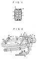
- Fig. 1 is a cross sectional view of the operation section of a prior art endoscope; and
- Figs. 2 to 14 show the endoscope according to an embodiment of the invention, in which:
- Fig. 2 is a perspective view schematically showing the endoscope as a whole;
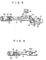
- Figs. 3 and 4 are perspective views of a main body of the operation section from different directions;
- Fig. 5 is a sectional view showing a portion of a structure wherein a light guide cable is connected to the operation section;
- Fig'. 6 is a sectional view taken along line VI-VI of Fig. 5;
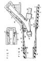
- Fig. 7 is a sectional view showing a joining portion of a channel mouth;
- Fig. 8 is a sectional view showing a joining portion between the operation section and insertion section of the endoscope;
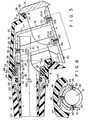
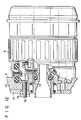
- Fig. 9 is a sectional view of the operation section;
- Figs. 10 and 11 are sectional views which show the internal mechanism of the operation section;
- Fig. 12 is a sectional view showing a connection portion between the operation section and ocular section;
- Fig. 13 is a cross sectional view of a casing; and
- Fig. 14 is a view explaining the function of the casing.
- An embodiment of the invention may now be described with reference to Figs. 2 to 14.
- Fig. 2 schematically shows an entire endoscope. This endoscope is comprised of an
insertion section 1, anoperation section 2 and a lightguide cable section 3. Theoperation section 2 is comprised of amain body 4 as shown in Fig. 3, and a casing 5 (Figs. 2 and 9) consisting of synthetic resin and so arranged as to cover and contain themain body 4. Further, thecasing 5 is divided into two parts, one of which is acasing body 6 made substantially rectangular and shaped like a hollow box and the other of which is acylindrical gripping cover 7. Those two parts are joined together in such a manner that their hollow portions are allowed to come into contact with each other. Thecasing body 6 is provided with anocular portion 8, an air/water feed control element 9,suction control element 11 and a bending operation knob 12 (Fig. 3). Note here that the reference numeral 10a in Fig. 2 denotes an intermediate coupling portion of an air/water feeding tube while the reference numeral 10b denotes an intermediate coupling portion of asuction tube 54 as later described. These intermediate coupling portions 10a and 10b are disposed within thegripping cover 7. Further, an inclined face 13 is formed on the portion of thecasing body 6 opposite to the portion where thebending operation knob 12 is provided. This inclined face 13 is provided with anopening portion 14 in such a manner that thisportion 14 is opposed to themain body 4 of the operation section. Theopening portion 14 is attached with acasing cover 15, that is, alid member 15, which consists of synthetic resin in such a manner that the opening is closed by thelid member 15. To thiscasing lid member 15, there is connected a base end of the above-mentionedlight guide cable 3. - The joining structure wherein the
casing lid member 15 is joined or coupled to thecasing body 6, as well as the connecting structure wherein thelight guide cable 3 is connected to themain body 4 of theoperation section 2, may now be described in detail, with reference to Figs. 5 and 6. Afixing metal fitting 17 is provided on the surface of themain body 4 in opposition to theopening portion 14. This fixingmetal fitting 17 is formed or prepared by fabricating, i.e., by pressing a thin metal plate, such as that which has a Japanese Industrial Standard of, e.g., C 1720P, C 5211P, C 2680P, C 2800P, A 5052P, SPCC, SUS 304CP, etc., and is comprised of atop plate portion 18 and threesupport leg portions 19 made integral with thetop plate portion 18 and bent from the same. Further, a bent portion 19a is formed on the lower end portion of each of the threesupport leg portions 19 and is formed with an attachinghole 19b, through which afastening screw 20 is idly inserted via a spring washer 20a. Thefixing metal fitting 17 is attached to themain body 4 of the operation section by means of thefastening screw 20. Accordingly, thetop plate portion 18 of the fixing metal fitting 17 and upper portions of thesupport leg portions 19 are allowed to protrude from theopening portion 14 of thecasing body 6. Thetop plate portion 18 and supportleg portions 19 thus protruded are formed with attachingholes 21. To this fixingmetal fitting 17 there is connected a base end portion of thelight guide cable 3. That is, thelight guide cable 3 is comprised of aflexible tube 22 used to have equipped therein elongate members such as a light guide fiber f, a fluid transport pipe t and an electric signal wire !, and amouthpiece pipe 23 fitted to an end portion of thisflexible tube 22. A base end portion of themouthpiece pipe 23 is formed with a notchedportion 24, which is formed withscrew holes 25 arranged to oppose said attachingholes 21 of the fixingmetal fitting 17. Thus, the fixing metal fitting 17 and the base end portion of themouthpiece pipe 23 are integrally fixed to each other by screwing into thescrew holes 25 thefixing screws 26 passing through the attachingholes 21. Further, onto the base end portion of theflexible tube 22 there is fitted a breakpreventive rubber tube 27 whose open end has amouthpiece 28 screwed thereinto and thus joined thereto. Further, a base end portion of afastening ring 29 is screwed into and joined and fixed to thismouthpiece 28. The fasteningring 29 is allowed to protrude from the end face of the breakpreventive rubber tube 27, the protruded portion thereof being formed with a first annular groove 30 on its inner peripheral surface and a second annular groove 31 on its outer peripheral surface. The first and second annular grooves 30 and 31 are formed in such a manner that they adjoin to each other in the axial direction of the lightguide cable section 3. The first and second annular grooves 30 and 31 have received thereinresilient seal members stepped portion 34 is provided on the outer peripheral surface of the portion of thefastening ring 29 located between the first and second annular grooves 30 and 31; while, on the other hand, an internally threaded portion 35 is formed on the inner peripheral surface of the fastening ring corresponding to the second annular groove 31. - This internally threaded portion 35 is screwed onto an externally threaded
portion 36 provided on the outer peripheral surface of themouthpiece pipe 23. Further, the base end face of thefastening ring 29 is integrally provided with a fastening annular portion 37 shaped like a wedged in section, in such a way that this portion is engaged with thecasing lid member 15. - Further, the
opening portion 14 provided with reference to the inclined face 13 of thecasing body 6 is formed in a rectangular shape and is provided, on its inner peripheral edge, with an inclinedpressure receiving portion 38. Thecasing lid member 15 is made rectangular, in such a manner that it closes theopening portion 14; and is provided, on its outer peripheral edge, with an inclinedpressure application portion 39, which is to be joined to the. inclinedpressure receiving portion 38. Thecasing lid member 15 is also formed, along its outer peripheral edge, with aprotruded portion 40 at a position inward of the inclinedpressing portion 39. On the outer side of the protrudedportion 40, there is fitted aresilient seal member 41 consisting of 0-ring which is intended to seal, on a watertight basis, the portion between the outer side of the protruded portion and the inner peripheral surface of thecasing body 6. On the outer surface of thecasing lid member 15, there is integrally protruded a squarehollow member 42 which covers thefixing metal fitting 17. A tip end portion of the fittinghollow member 42 is provided with acircular fitting portion 43 fitted onto the outer periphery of thefastening ring 29, and an opening end of thisfitting portion 43 is formed with afitting step portion 44 opposing thestepped portion 34 of thefastening ring 29. An innerperipheral protrusion portion 45 is provided on a portion, opposing a part of the fastening annular portion 37, of the inner peripheral surface of the fitting squarehollow member 42. This innerperipheral protrusion portion 45 is formed with an engaging notchedportion 46 which is to be brought into engagement with the fastening annular portion 37. - The method of connecting, for assembly, the
light guide cable 3 to themain body 4 of the operation section fixed to thecasing 5 may be described as follows. The fixing metal fitting 17 is inserted into thecasing body 6 from the openingportion 14 thereof and thesupport leg portions 19 are fastened and secured to themain body 4 by means of the fixing screws 20. In this case, since the attachingholes 19b of thesupport leg portions 19 are each made large enough (in diameter) to permit the fixingscrew 20 to idly pass therethrough, it is possible to fix the fixing metal fitting 17 to themain body 4 of the operation section on an adjustable basis. Thereafter, the base end portion of themouthpiece pipe 23 provided with reference to theflexible tube 22 of thelight guide cable 3 is positioned with respect to thetop plate portion 18, whereby themouthpiece pipe 23 and the fixing metal fitting 17 are integrally attached to each other by means of the fixing screws 26. In this case as well, since the fixing metal fitting 17 is,formed of a thin metal plate or sheet, the positioning of themouthpiece pipe 23 can be adjusted by elastically deforming the fixingmetal fitting 17. Thus, it is also possible to position the metal fitting 17 relative to the fitting squarehollow member 42 of thecasing lid member 15, which will be described later. On the other hand, after theresilient seal member 41 is fitted onto the protrudedportion 40 of thecasing lid member 15, the fitting squarehollow member 42 of thecasing lid member 15 covers theflexible tube 22 of thelight guide cable 3. Then, thecasing lid member 15 is moved toward thecasing body 6; and, while the fixing metal fitting 17 is enclosed by thehollow member 42, the inclined pressingportion 39 of thecasing lid member 15 is allowed to abut against the inclinedpressure receiving portion 38 of thecasing body 6, thereby closing the openingportion 14. Thereafter; thefastening ring 29 fitted with theresilient seal members preventive rubber tube 27 integrally joined thereto, cover theflexible tube 22 of thelight guide cable 3, thereafter to screw the internally threaded portion 35 onto the externally threadedportion 36 of themouthpiece pipe 23 of theflexible tube 22, thereby to fasten the fastening ring onto the same. In this case, since the axis 15a of thelight guide cable 3 is eccentric from theaxis 42a of the fitting squarehollow member 42, by a, the fastening of thefastening ring 29 causes theresilient seal member 33 to exert a force acting in a direction perpendicular to the axis 15a, namely in the direction of arrow A. Further, since the fastening annular portion 37 of thefastening ring 29 is engaged with the engaging notchedportion 46 of the innerperipheral protrusion 45 of the fitting squarehollow member 42, the fastening of thefastening ring 29 causes a force acting in the direction indicated by arrow P to be applied to the innerperipheral protrusion 45. As a consequence, thecasing lid member 15 and thecasing body 6 are adhered or bonded to each other by a joining of the inclined pressingportion 39 to the inclinedpressure receiving portion 38. Although, in this case, theresilient seal member 33 has its body biased by the fastening of thefastening ring 29, the sealing between thefastening ring 29 and thecasing lid member 15 is ensured, even when such resilient seal member has its body maximally biased to a value great enough to permit the creation of a clearance therebetween. Thus, the sealing of thefastening ring 29 to themouthpiece pipe 23 is completely achieved by theresilient seal member 32, on a watertight basis. On the other hand, the sealing of thecasing body 6 to thecasing lid member 15 is accomplished by means of theresilient seal member 41, on a watertight basis. - Meanwhile, the above-mentioned
gripping cover 7 has an outer diameter and a length which are suitable for gripping by an examiner using only one hand. On the side face of an end portion of thecover 7 located on the side of theinsertion section 1, there is integrally formed an attachinghollow portion 48 used to mount achannel mouthpiece 47 thereto as shown in Figs. 7 and 8. That is, thechannel mouthpiece 47 is removably inserted from outside and fitted into the attachinghollow portion 48 and is fixed thereto by means of a pair of attachingscrews 51, as shown in Fig. 7. Further, as shown in Fig. 8, thechannel mouthpiece 47 is connected to one end of a three-way joint 52. To one of the remaining ends of the three-way tube, there is connected achannel tube 53, and asuction tube 54 is connected to the other of said remaining ends. This provides the above-mentioned intermediate coupling portion 10b wherein thechannel tube 53 and thesuction tube 54 are respectively connected to the ends of the three-way joint 52. - Also, the
main body 4 of the operation section disposed within thecasing 5 as shown in Fig. 3, is comprised of a plurality of members; or, as in this embodiment; is comprised of abase plate 56 made of metal, a pair offrames 57 and acylindrical member 58. More specifically, a pair ofbent piece portions 59 are provided on an end portion of themetallic base plate 56 located on the side of theinsertion section 1. Further, a pair of saidframes 57 are screwed and connected, at one end, to thebent piece portions 59, respectively, and, at the other end, to the side surface of thecylindrical member 58. Thebase plate 56 is so disposed as to extend through thecasing body 6 and thegripping cover 7. The paired frames are disposed within thegripping cover 7, and thecylindrical member 58 is disposed in such a manner as to extend and project from a tip end opening portion of thegripping cover 7. To thecylindrical member 58, the said three-way joint 52 is attached and stabilized by means ofsetscrews 61, as shown in Fig. 8. Further, abase end portion 62 of the flexible tube extending from theinsertion section 1 is connected, by means of acheck ring 63, to an extended tip end portion of thecylindrical member 58. Further, a breakpreventive member 65 consisting of resilient material having a relatively high rigidity is connected to thecylindrical member 58 through a connectingpipe 64. Further, a cylindricalwatertight cover 66 is fitted onto the outer periphery of thecylindrical member 58 and is partially allowed to enter the opening end of thegripping cover 7 and is connected thereto on a watertight basis. The other end of thewatertight cover 66 is joined to an end face of the breakpreventive member 65. Ring-likeresilient packings 67 are interposed between the joining portions of thewatertight cover 66 and thegripping cover 7, between the joining portions of thewatertight cover 66 and thecylindrical member 58 located on the side of theinsertion section 1, and between thecylindrical member 58 and a base end portion of theinsertion section 1, respectively, so as to ensure the watertightness therebetween. - Meanwhile, on the inner peripheral surface of an opening portion of the
gripping cover 7 located on the side of theinsertion section 1, a receiving portion.68 is formed, whichportion 68 projects toward the central axis thereof, over the entire inner peripheral surface of said opening portion, as shown in Fig. 8. Against this receivingportion 68, a pair of nut-like juxtaposed fastening members 71 are abutted, being screwed onto anexternal thread 69 formed on the outer peripheral surface of thecylindrical member 58. When these fastening members 71 are advanced toward the side of thegripping cover 7, it is possible to press this gripping cover and at the same time themain body 4 of the operation section is pulled as a reaction of this pressing operation. - On the other hand, the other end of the
main body 4 of theoperation section 2, i.e., the end of thebase plate 56 located on the side of theocular portion 8, is attached and fixed, for example, to aside wall 74 of thecasing body 6 by means of a pair of members, such asmetallic members side wall 74 is sandwiched between the pairedmetallic members setscrews 75, each passing through these three members, and by mean of nuts 76. - The inner
metallic member 72 has apiece 77 formed. on one side edge thereof, whichpiece 77 is screwed onto thebase plate 56. Further, the parts of theocular portion 8 are assembled on the outermetallic member 73, as shown in Fig. 12. - The
casing body 6 of thecasing 5 and thegripping cover 7 are connected to each other in a manner such as that shown in Fig. 9. That is, thecasing body 6 is formed with aprojection 79 which projects toward the side of thegripping cover 7 from a joiningznd face 78 of thecasing body 6 and which has a configuration corresponding to that of the opening portion of thegrippint cover 7. Further, saidprojection 79 is so arranged as to be fitted into the opening end of thegripping cover 7. Further, an inner peripheral surface of the opening end portion of thegripping cover 7 fitted with theprojection 79 is made large in diameter correspondingly to the thickness of theprojection 79, whereby astep portion 80 is formed. A projection portion 80a allowed to project toward thecasing body 6 is formed on a tip end of a rising wall surface of thisstep portion 80 while, on a tip end of theprojection 79 as well, a projection portion 79a is so formed as to corresponding to the projection portion 80a. The projection portions 79a and 80a are each formed with an inclined surface at the side of the bottom surface of thestep portion 80, and a.resilient packing 81 shaped like a ring is fitted into a space portion thus enclosed by those surfaces. - The
base plate 56 of themain body 4 of the operation section has a bending operation mechanism mounted thereon, as-shown in Fig. 9. On the upper surface of one end portion of thebase plate 56 located within thecasing body 6, there is provided a fixingportion 82a of ashaft 82 provided projecting from the base plate. Aninner sleeve 83 and anouter sleeve 84 are rotatably fitted onto theshaft 82. Thesleeves shaft 82, in such a manner as to be rotatable thereabout; and are allowed, at their other side ends, to project from thecasing body 6, being respectively connected to the above-mentioned bending operation knobs 12 (only one of which is shown in Fig. 3). Further, on the upper surface of the other end of thebase plate 56 allowed to project into thegripping cover 7, a partitioningmember 86 which U-shaped in cross section is attached and fixed to the base plate 56 (longitudinally thereof) by means of a fixingplate 87, through its intermediate bottom portion. Outside each side wall of the partitioningmember 86, apassage 89 is defined by a definingwall 88, in such a manner that theresultant passages 89 are arranged at upper and lower stages, with the partitioning member interposed therebetween. The definingwall 88 is divided into two parts, one being an inner defining wall 88a and the other being an outer definingwall 88b, in the widthwise direction of thepassage 89. The inner and outer definingwalls 88a and 88b are supported by and fixed to supportportions base plate 56, at their midway positions taken in their longitudinal directions and at their ends located on the side of thesprockets 85. - An attaching
plate 91 is erected on the upper surface of the end portion of thepartitioning wall member 86 located on the side opposite to that at which thesprockets 85 are disposed. To this attachingplate 91, there is joined and fixed a flat-plate like retainingmember 92 having a width greater than that of thepartitioning wall member 86. On both ends of this retainingmember 92 taken in the widthwise direction thereof, sets ofnotches 93, which sets each consist of two notches, are formed correspondingly to thepassages 89, respectively. At thenotch 93, there is provided a hollowcylindrical regulating member 94 formed with a step portion 94a made smaller in diameter at a midway position taken in the axial direction thereof, in a state wherein the step portion 94a is engaged with thenotch 93 in such a manner that this regulatingmember 94 is thereby prevented from being moved in the axial direction thereof. This regulatingmember 94 is held in place in such a manner that the disengagement thereof from thenotch 93 is prevented by the abutment of an end portion of the outer definingwall member 88b against the peripheral surface of the regulatingmember 94. Further, into the hollowcylindrical regularing member 94, a base end portion consisting of a flexiblewire guide pipe 95 comprised of a coil of a close winding or the like is inserted into theinsertion section 1 throughout the entire length thereof, whereby said base end portion is fixed by brazing to the regulatingmember 94, by the use of abrazing material member 96a. Awire 96 is inserted through thewire guide pipe 95. This wire is connected and fixed at its tip end to a top (not shown) constituting the bending portion, and is lead into thepassage 89 at its base end side. A connectingmember 97 is connected to the base end of thewire 96 guided into and through thepassage 89. An end portion of a chain 98 engaged at its midway position with the above-mentioned.sprocket 85 is connected to the connectingmember 97. Further, on the connectingmember 97, there is planted or provided anabutment member 99 in such a manner that themember 99 intersects the axial line of thewire 96 at right angles thereto. A part of thisabutment member 99 is allowed to project toward an outside of thebase plate 56 taken in the widthwise direction thereof. The outer peripheral surface of this projected portion of the abutment member is formed into aninclined surface 100 defining an acute angle with an end face thereof. - On the other hand, a
wall portion 101 formed by bending a part of thebase plate 56 or a separate member into the shape of the letter U-shape' is provided between the first andsecond support portions base plate 56. Asupport hole 102 is formed in one way portion of thiswall portion 101 located along the widthwise direction of thebase plate 56. On thissupport hole 102, there is rotatably,supported ascrew 103 having a receivingportion 103c between its threadedportion 103a and itshead portion 103b, through this receivingportion 103c. Thescrew 103 is provided in such a manner that its axial line is made parallel to the axial line of thewire 96 and is located at a position, on the outside of thebase plate 56 taken in the widthwise direction thereof, which is more outward of this plate than the axial line of thewire 96. A terminal end of the threadedportion 103a is engaged with asupport hole 104 formed in thesecond support portion 90. Astopper 105 is screwed onto the threadedportion 103a of thescrew 103 and has a height slightly lower than the height of thepassage 89. As a result, when thescrew 103 is allowed to rotate about its axis, the upper surface of thestopper 105 is allowed to abut against an upper wall surface of thepassage 89 and is thereby prevented from being rotated in such a way as to be moved forwards and backwards through thepassage 89. Here, it should be noted that thepassage 89 corresponding to a portion wherein thescrew 103 is provided is defined by the above-mentioneddefining wall 88b. On one side of thestopper 105 directed toward thepartitioning wall member 86, aninclined surface 106 having an angle of inclination corresponding to theinclined surface 100 of theabutment member 99 is formed. By abutment of theinclined surface 100 of theabutment member 99 against theinclined surface 106 of thestopper 105, the travel of thewire 96, i.e., the maximum bending angle of the bending portion defined in the rightward and leftward directions, as well as in the upward and downward directions, is limited. - The
head portion 103b of thescrew 103 is formed with anengaging bore 107 allowed to pass therethrough, in the radial direction thereof. An engagingstopper spring 108 prepared by bending a wire into a waveform configuration is engaged at one end with said engagingbore 107. Further, the engagingstopper spring 108 is pressed at the other end against thefirst support portion 90a in a state wherein it is kept compressed. Accordingly, thescrew 103 is prevented by the engagingstopper spring 108 from being rotated about its axis, and an end face of thehead portion 103b is pressed due to the restoring force of the engagingstopper spring 108 against a side face of thewall portion 101, whereby thehead portion 103b is prevented from being moved in a direction in which it is escaped from, or spaced away from, thesupport hole 102. - In the bending operation mechanism having the foregoing construction, when the
sprocket 85 is rotated by the bendingoperation knob 12 for the purpose of bending the bending portion of theinsertion section 1, and the chain 98 is thus allowed to travel, thewire 96 located in one of saidpassages 89 in the widthwise direction of thebase plate 56 is pulled, while thewire 96 located in the other of saidpassages 89 in a similar direction is pushed. Accordingly, the bending portion is bent toward the side of thewire 96 pulled. When thewire 96 is further pulled, theinclined surface 100 of theabutment member 99 provided to the connectingmember 97 connecting thewire 96 at the base end thereof to the chain 98 is brought into abutting engagement with theinclined surface 106 of thestopper 105. This makes it impossible to pull thewire 96 any further. Thus, the maximum bending angle of the bending portion is defined by thestopper 105. Further, when theabutment member 99 is allowed to abut against thestopper 105, thescrew 103 is pressed onto the side face of thesecond support portion 90 through thestopper 105. At this time, however; in thisscrew 103, the end face of thehead portion 103b thereof is allowed to abut against the side face of thewall portion 101, whereby thescrew 103 is prevented from being axially moved, along with thestopper 105. As a result, the possibility that the maximum bending angle of the bending portion would become greater than an initial preset angle may be eliminated. - The following procedural operations should be conducted for the purpose of changing the maximum bending angle of the bending portion. The engaging
stopper spring 108 provided, in a state wherein it is compressed, between thefirst support portion 90a and theengaging bore 107 of thehead portion 103b of thescrew 103 is dismounted by being further compressed. Next, thescrew 103 is rotated, whereby thestopper 105 is displaced toward thesecond support portion 90. Thereafter, the bending portion is bent until it has a predetermined bending angle, by rotation of the bendingoperation knob 12. Then, while the bendingoperation knob 12 is kept thus rotated, thescrew 103 is rotated in the opposite direction to that in which the preceding rotation thereof was made, until theinclined surface 106 of thestopper 105 abuts against theinclined surface 100 of theabutment member 99. Subsequently, the engagingstopper spring 108 is again mounted between thefirst support portion 90a and theengaging bore 107 of thehead portion 103b of thescrew 103, whereby thestopper 105 is fixed to a predetermined position through thescrew 103. Thus, the maximum bending angle of the bending portion is set by thestopper 105. - Although a slight rotation of the
screw 103 from a prescribed position thereof is necessary, to cause the end portion of the engagingstopper spring 108 to come into engagement with theengaging bore 107, thestopper 105 is almost unmoved, due to such slight rotation of thescrew 103, only if the pitch of thescrew 103 is made sufficiently small. Thus, there is no positive effect on the maximum bending angle of the bending portion. - Meanwhile, flexure
preventive stopper members support portions 90, respectively, as shown in Figs. 11 and 13. The flexure preventive stopper members lll, 112 are each made of a synthetic resinous material and are mounted in such a manner that their external threaded portions formed on their one-side end portions are screwed into the threaded bores 104 formed in thesupport portions 90. The other side ends of these flexurepreventive stopper members casing 5; or, in this case, against the inner wall surface of thecasing body 6. As shown in Fig. 4, astopper piece 113 serving as a separate flexure preventive stopper member is screwed and fixed to thebase plate 56 at a position thereof which is opposite to that at which the flexurepreventive stopper members stopper piece 113 abuts against the inner wall surface (i.e., the inner wall surface opposite to that against which the flexurepreventive stopper members casing body 6. It should be noted here that, preferably, the flexurepreventive stopper members stopper piece 113 are disposed substantially on flat planes intersecting the surface of thebase plate 56 at right angles thereto, as shown in Fig. 13. That is, since the flexure preventive stopper members lll, 112 and thestopper piece 113 are provided on the sides of themain body 4 of the operation section at which the same is flexed and swollen, for example, at the time of the bending operation, in such a manner that they are allowed at all times to abut against the inner wall surfaces of thecasing body 6, themain body 4, especially thebase plate 56, is prevented from being flexed at the time of, for example, the bending operation, even when it tends to be flexed. The prevention of such flexure is completely achieved by thestopper members stopper piece 113, although this prevention is also due to the fact that a pulling force acts upon themain body 4 of the operation section, as later described. This also produces the effect of making it possible to construct themain body 4 of the operation section in such a way that the same is made thinner and more compact. Further, only a very small stress is applied to thestopper members stopper piece 113 due to their abutment against thecasing body 4, and no unnecessary concentrated stress is applied thereto. Here, it should be noted that the flexurepreventive stopper members the'stopper piece 113 are not required to be kept in constant abutment against the inner wall of thecasing body 6 in a state wherein they are cohered to this inner wall, but may be spaced therefrom to such an extent that, when themain body 4 has been flexed slightly, they may abut against said inner wall. - Thus, the assembling structure of the
operation section 2 is so disposed that the hollowbox casing body 6 and the cylindricalgripping cover 7 are joined together to form thecylindrical casing 5 as a whole; themain body 4 is inserted and disposed within saidcasing 5; and the ends of thecasing 5 are supported by themain body 4 of the operation section, in such a manner as to afford a pulling force to pull themain body 4. Thus, the end of themain body 4 of theoperation section 2 located on the side of theocular portion 8 is attached and fixed to theside wall 74 of thecasing body 6 by utilizing said pair ofmetallic members cylindrical member 58 of the end portion, located on the side of theinsertion section 1, of themain body 4 of the operation section is supported in a state wherein the fastening member 71 is pressed against the receivingportion 68 of thegripping cover 7, and themain body 4 of the operation section receives a pulling force while, on the other hand, thecasing 5 receives a compression force as a reaction. Further, the resilient packing 81 disposed between thecasing body 6 and thegripping cover 7 is compressed, whereby watertightness is ensured therebetween. - Meanwhile, the
casing 5 resists the flexure, buckling and bending forces resulting from its being compressed. However, since thecasing 5 is designed to occupy the outermost position of theoperation section 2, in particular, and is formed into a hollow box and into a cylinder, thecasing 5 has a large section modulus, even when its thickness is reduced. Accordingly, it is possible to makethe.casing 5 fine and light; and, at the same time, this casing can have a high resistance to the compression and the bending force. Since, on the other hand, themain body 4 of the operation section is so constructed that it receives a pulling force, this main body can be made thin and fine by being formed of metal or the like. That is, since themain body 4 of the operation section can be so designed as to have a sufficiently high mechanical strength against the pulling force, even when it is made thin and fine, this main body can be formed into a compact structure. Moreover, since themain body 4 has a pulling stress at all times, it offsets the compression force acting upon theoperation section 2. Further, since the pulling stress is at all times afforded to themain body 4 of the operation section, thismain body 4 has a higher resistance to the bending force than in the case where themain body 4 .has no pulling stress. - Still further, where the
casing body 6 and thegripping cover 7 tend to be separated from one another at the face of the abutment therebetween; and, thus, the casing tends to be bent at this face, as shown in Fig. 14 by two-dot chain lines, themain body 4 of the operation section must be bent and increased in length (QP < QR). However; since, as mentioned above, the bending and the increase in length of themain body 4 of the operation section are lessened, the variation likely to occur in the casing is suppressed. Accordingly, the bending of the casing at the position of abutment between thecasing body 6 and thegripping cover 7 is also prevented. For the above-mentioned reasons, theoperation section 2 can be not only constructed such that it has a sufficiently high resistance to the pulling force and is made fine and light in weight, but can also have a sufficiently high resistance to the compression and bending force as well. In the prior art structure, when an attempt is made-to obtain a sufficiently high resistance to, or mechanical strength against, the compression and bending force, theoperation section 2 becomes bulky or large in mass and heavy and besides has an excessive strength against the pulling force thus to have a uselessness in that regard. In the above-mentioned structure of the present invention, however, the distribution of the sectional area and weight involved is made such that the portions of themain body 4 of the operation section where inconvenience arises to obtain a strength against the compression and bending force are reduced in sectional area and weight and that the sectional area and weight of the outermost casing member is increased by that extent. Thus, according to the structure of the present invention, theoperation section 2, while the strengths thereof against the pulling, compression and bending forces are being made optimum, is made fine and light in weight and also has a sufficiently high strength. - Moreover, in the assembling structure mentioned above, when the
casing body 6 is dismounted, the connecting or joining portions contained therein are exposed, with the result that the efficiency with which the assembling operation is carried out increases. Also, since the sealing portion between thecasing body 6 and thegripping cover 7 may easily be formed as a simple ring-like joining portion, the sealing structure at that sealing portion is simple and permits a reliable sealing between both. In this regard, it should also be mentioned that the mounting of thecasing body 6 to thegripping cover 7 is achieved by the pressing of one against the other, by means of the fastening member, and does not require any superfluous through-hole, such as a hole for permitting the passage therethrough of a setscrew or the like, with the result that the sealability therebetween is increased. In addition, since no abrasion occurs, due to the eccentricity of the through-hole relative to the setscrew, or vice versa, it is easy to use a synthetic resinous material; and, at the same time, the manufacturing cost involved is decreased, if the molding technique is applied. - Further; since, in the above-mentioned structure, the
main body 4 of the operation section is stabilized in such a way that theside wall 74 of thecasing body 6 is sandwiched between themetallic members casing body 6 is thus lessened with the result that the durability thereof is increased. - Still further, at the time of bending operation, the compression and bending forces are applied.to the
main body 4 of the operation section between the portion of fixing the base end of the bending operationwire guide pipe 95 and the portion of fixing the bending wire advancing and retreating means. However, since such compression and bending forces are allowed to act on that portion of main body between both which has a pulling force applied in advance, the compression force is offset by this pulling force while the bending force is resisted by this pulling force to a high degree. - As stated above, according to the present invention, it is possible to make the operation section light in weight while providing a structure therefor which has sufficient mechanical strength to resist compression and bending forces, having high durability. In addition, since the assembling operability for the operation section is high the sealability therefor can also be enhanced, and the manufacturing cost therefor is also reduced. These are additional advantages or effects of the present invention.
Claims (7)
wherein said casing includes:
Applications Claiming Priority (4)
| Application Number | Priority Date | Filing Date | Title |
|---|---|---|---|
| JP57138259A JPS5928942A (en) | 1982-08-09 | 1982-08-09 | Endoscope |
| JP138259/82 | 1982-08-09 | ||
| JP143682/82 | 1982-08-19 | ||
| JP57143682A JPS5934238A (en) | 1982-08-19 | 1982-08-19 | Endoscope |
Publications (3)
| Publication Number | Publication Date |
|---|---|
| EP0100977A2 true EP0100977A2 (en) | 1984-02-22 |
| EP0100977A3 EP0100977A3 (en) | 1984-11-07 |
| EP0100977B1 EP0100977B1 (en) | 1988-01-20 |
Family
ID=26471357
Family Applications (1)
| Application Number | Title | Priority Date | Filing Date |
|---|---|---|---|
| EP83107511A Expired EP0100977B1 (en) | 1982-08-09 | 1983-07-29 | Endoscope |
Country Status (3)
| Country | Link |
|---|---|
| US (1) | US4552129A (en) |
| EP (1) | EP0100977B1 (en) |
| DE (1) | DE3375430D1 (en) |
Families Citing this family (6)
| Publication number | Priority date | Publication date | Assignee | Title |
|---|---|---|---|---|
| JP2002238831A (en) * | 2001-02-16 | 2002-08-27 | Fuji Photo Optical Co Ltd | Endoscope |
| JP4155072B2 (en) * | 2003-03-26 | 2008-09-24 | フジノン株式会社 | Endoscope |
| EP2868252A4 (en) * | 2012-10-22 | 2016-07-13 | Olympus Corp | Endoscope |
| JP5657843B1 (en) * | 2013-02-07 | 2015-01-21 | オリンパスメディカルシステムズ株式会社 | Endoscope operation unit structure |
| WO2016009690A1 (en) * | 2014-07-17 | 2016-01-21 | オリンパス株式会社 | Endoscope |
| JP6081684B1 (en) * | 2015-06-29 | 2017-02-15 | オリンパス株式会社 | Endoscope |
Citations (4)
| Publication number | Priority date | Publication date | Assignee | Title |
|---|---|---|---|---|
| US3788303A (en) * | 1972-01-24 | 1974-01-29 | American Cystoscope Makers Inc | Orthogonally deflectable endoscope |
| DE2914748A1 (en) * | 1978-04-12 | 1979-10-18 | Medos Kenkyusho Kk | GAME ADJUSTMENT DEVICE FOR AN ENDOSCOPE |
| EP0028396A2 (en) * | 1979-10-31 | 1981-05-13 | Olympus Optical Co., Ltd. | Endoscope |
| EP0032595A2 (en) * | 1980-01-17 | 1981-07-29 | Olympus Optical Co., Ltd. | Endoscope |
Family Cites Families (4)
| Publication number | Priority date | Publication date | Assignee | Title |
|---|---|---|---|---|
| US1627941A (en) * | 1924-10-16 | 1927-05-10 | Reinhold H Wappler | Surgical instrument |
| US3294085A (en) * | 1963-09-27 | 1966-12-27 | American Cystoscope Makers Inc | Endoscope |
| JPS5610321Y2 (en) * | 1974-12-26 | 1981-03-09 | ||
| JPS5582884A (en) * | 1978-12-19 | 1980-06-21 | Olympus Optical Co | Flexible tube and its manufacture |
-
1983
- 1983-07-29 DE DE8383107511T patent/DE3375430D1/en not_active Expired
- 1983-07-29 EP EP83107511A patent/EP0100977B1/en not_active Expired
- 1983-08-02 US US06/519,741 patent/US4552129A/en not_active Expired - Lifetime
Patent Citations (4)
| Publication number | Priority date | Publication date | Assignee | Title |
|---|---|---|---|---|
| US3788303A (en) * | 1972-01-24 | 1974-01-29 | American Cystoscope Makers Inc | Orthogonally deflectable endoscope |
| DE2914748A1 (en) * | 1978-04-12 | 1979-10-18 | Medos Kenkyusho Kk | GAME ADJUSTMENT DEVICE FOR AN ENDOSCOPE |
| EP0028396A2 (en) * | 1979-10-31 | 1981-05-13 | Olympus Optical Co., Ltd. | Endoscope |
| EP0032595A2 (en) * | 1980-01-17 | 1981-07-29 | Olympus Optical Co., Ltd. | Endoscope |
Also Published As
| Publication number | Publication date |
|---|---|
| DE3375430D1 (en) | 1988-02-25 |
| EP0100977A3 (en) | 1984-11-07 |
| EP0100977B1 (en) | 1988-01-20 |
| US4552129A (en) | 1985-11-12 |
Similar Documents
| Publication | Publication Date | Title |
|---|---|---|
| US4490576A (en) | Connector for use with jacketed metal clad cable | |
| US4960964A (en) | Quick set grounding assembly | |
| US4552129A (en) | Endoscope | |
| FI971751A (en) | Connector for long cable | |
| KR950009031A (en) | Retained Seal Assembly | |
| EP1089155A2 (en) | Adjustable pedal-pocketed gears | |
| US5447343A (en) | Rigid endoscope connector | |
| EP0647464A3 (en) | Spiral filtration module having bypass prevention flange. | |
| JPH0243484B2 (en) | ||
| JPH0650318A (en) | Device for assembly by clamp of elastic compressive part | |
| DE3708131A1 (en) | WATERPROOF ELECTRICAL CONTACT KIT, ESPECIALLY ON AN ENDOSCOPE | |
| JPH0416166B2 (en) | ||
| JP4787427B2 (en) | Seal structure for waterproof electronic devices | |
| ATE208020T1 (en) | FASTENING ELEMENT | |
| JPH035166B2 (en) | ||
| JPH034205B2 (en) | ||
| DE3728735A1 (en) | Waterproof housing for a video-camera recorder (camcorder) | |
| GB2095051A (en) | A cable gland | |
| JP3246799B2 (en) | Endoscope bending operation device | |
| KR810000494Y1 (en) | Band clamp for t.v deflect york | |
| JPH0546305Y2 (en) | ||
| KR960006828Y1 (en) | Structure for fixing a cabinet | |
| JPS637203Y2 (en) | ||
| JP3521419B2 (en) | Corner pole device for automobile | |
| JPH0426081Y2 (en) |
Legal Events
| Date | Code | Title | Description |
|---|---|---|---|
| PUAI | Public reference made under article 153(3) epc to a published international application that has entered the european phase |
Free format text: ORIGINAL CODE: 0009012 |
|
| AK | Designated contracting states |
Designated state(s): DE FR GB |
|
| PUAL | Search report despatched |
Free format text: ORIGINAL CODE: 0009013 |
|
| AK | Designated contracting states |
Designated state(s): DE FR GB |
|
| 17P | Request for examination filed |
Effective date: 19841117 |
|
| 17Q | First examination report despatched |
Effective date: 19861030 |
|
| GRAA | (expected) grant |
Free format text: ORIGINAL CODE: 0009210 |
|
| AK | Designated contracting states |
Kind code of ref document: B1 Designated state(s): DE FR GB |
|
| REF | Corresponds to: |
Ref document number: 3375430 Country of ref document: DE Date of ref document: 19880225 |
|
| ET | Fr: translation filed | ||
| PLBE | No opposition filed within time limit |
Free format text: ORIGINAL CODE: 0009261 |
|
| STAA | Information on the status of an ep patent application or granted ep patent |
Free format text: STATUS: NO OPPOSITION FILED WITHIN TIME LIMIT |
|
| 26N | No opposition filed | ||
| PGFP | Annual fee paid to national office [announced via postgrant information from national office to epo] |
Ref country code: FR Payment date: 19950711 Year of fee payment: 13 |
|
| PGFP | Annual fee paid to national office [announced via postgrant information from national office to epo] |
Ref country code: GB Payment date: 19950718 Year of fee payment: 13 |
|
| PG25 | Lapsed in a contracting state [announced via postgrant information from national office to epo] |
Ref country code: GB Effective date: 19960729 |
|
| GBPC | Gb: european patent ceased through non-payment of renewal fee |
Effective date: 19960729 |
|
| PG25 | Lapsed in a contracting state [announced via postgrant information from national office to epo] |
Ref country code: FR Effective date: 19970328 |
|
| REG | Reference to a national code |
Ref country code: FR Ref legal event code: ST |
|
| PGFP | Annual fee paid to national office [announced via postgrant information from national office to epo] |
Ref country code: DE Payment date: 20000724 Year of fee payment: 18 |
|
| PG25 | Lapsed in a contracting state [announced via postgrant information from national office to epo] |
Ref country code: DE Free format text: LAPSE BECAUSE OF NON-PAYMENT OF DUE FEES Effective date: 20020501 |