EP0096492A1 - Elongate electrical heaters - Google Patents
Elongate electrical heaters Download PDFInfo
- Publication number
- EP0096492A1 EP0096492A1 EP83302884A EP83302884A EP0096492A1 EP 0096492 A1 EP0096492 A1 EP 0096492A1 EP 83302884 A EP83302884 A EP 83302884A EP 83302884 A EP83302884 A EP 83302884A EP 0096492 A1 EP0096492 A1 EP 0096492A1
- Authority
- EP
- European Patent Office
- Prior art keywords
- strip
- conductors
- heating
- heater
- heating strip
- Prior art date
- Legal status (The legal status is an assumption and is not a legal conclusion. Google has not performed a legal analysis and makes no representation as to the accuracy of the status listed.)
- Granted
Links
Images


Classifications
-
- H—ELECTRICITY
- H05—ELECTRIC TECHNIQUES NOT OTHERWISE PROVIDED FOR
- H05B—ELECTRIC HEATING; ELECTRIC LIGHT SOURCES NOT OTHERWISE PROVIDED FOR; CIRCUIT ARRANGEMENTS FOR ELECTRIC LIGHT SOURCES, IN GENERAL
- H05B3/00—Ohmic-resistance heating
- H05B3/10—Heater elements characterised by the composition or nature of the materials or by the arrangement of the conductor
- H05B3/12—Heater elements characterised by the composition or nature of the materials or by the arrangement of the conductor characterised by the composition or nature of the conductive material
- H05B3/14—Heater elements characterised by the composition or nature of the materials or by the arrangement of the conductor characterised by the composition or nature of the conductive material the material being non-metallic
-
- H—ELECTRICITY
- H05—ELECTRIC TECHNIQUES NOT OTHERWISE PROVIDED FOR
- H05B—ELECTRIC HEATING; ELECTRIC LIGHT SOURCES NOT OTHERWISE PROVIDED FOR; CIRCUIT ARRANGEMENTS FOR ELECTRIC LIGHT SOURCES, IN GENERAL
- H05B3/00—Ohmic-resistance heating
- H05B3/40—Heating elements having the shape of rods or tubes
- H05B3/54—Heating elements having the shape of rods or tubes flexible
- H05B3/56—Heating cables
-
- H—ELECTRICITY
- H05—ELECTRIC TECHNIQUES NOT OTHERWISE PROVIDED FOR
- H05B—ELECTRIC HEATING; ELECTRIC LIGHT SOURCES NOT OTHERWISE PROVIDED FOR; CIRCUIT ARRANGEMENTS FOR ELECTRIC LIGHT SOURCES, IN GENERAL
- H05B3/00—Ohmic-resistance heating
- H05B3/10—Heater elements characterised by the composition or nature of the materials or by the arrangement of the conductor
- H05B3/12—Heater elements characterised by the composition or nature of the materials or by the arrangement of the conductor characterised by the composition or nature of the conductive material
- H05B3/14—Heater elements characterised by the composition or nature of the materials or by the arrangement of the conductor characterised by the composition or nature of the conductive material the material being non-metallic
- H05B3/146—Conductive polymers, e.g. polyethylene, thermoplastics
Definitions
- This invention relates to elongate electrical strip heaters.
- Many elongate electrical heaters e.g. for heating pipes, tanks and other apparatus in the chemical process industry, comprise two (or more) relatively low resistance conductors which are connected to the power source and run the length of the heater, with a plurality of heating elements connected in parallel with each other between the conductors (also referred to in the art as electrodes.)
- the heating elements are in the form of a continuous strip of conductive polymer in which the conductors are embedded.
- the heating elements are one or more resistive metallic heating wires.
- the heatinq wires are wrapped around the conductors, which are insulated except at spaced-apart points where they are connected to the heating wires.
- the heating wires contact the conductors alternately and make multiple wraps around the conductors between the connection points.
- elongate heaters are preferably self-regulating. This is achieved, in conventional conductive polymer heaters, by using a continuous strip of conductive polymer which exhibits PTC behavior. It has also been proposed to make zone heaters self-regulating by connecting the heating wire(s) to one or both of the conductors through a connecting element composed of a ceramic PTC material.
- This invention relates to improved elongate electrical heaters which comprise
- the heating strip comprises an elongate non-metallic resistive heating component, especially an elongate conductive polymer component.
- Such heaters are distinguished from conventional conductive polymer strip heaters and conductive polymer heaters as disclosed in U.S. U.S. Patents Nos. 4,271,350 and 4,309,597 by the requirement that the contact points are longitudinally spaced apart along the length of the heating strip. This is a difference which can result in very important advantages.
- One advantage results from the fact that elongate conductive polymer components are generally produced by methods which involve continuously shaping the conductive polymer composition into a strip, eg. by melt-extrusion or by deposition onto a substrate.
- the uniformity of the resistance of such a strip is greater in the longitudinal (or "machine") direction (eg. the direction of extrusion) than in the transverse direction.
- machine e.g. the direction of extrusion
- the current usually passes through the conductive polymer mainly or exclusively in the longitudinal direction.
- the new heaters can have improved power output and voltage stability.
- Another advantage is that if an arcing fault occurs in a known conductive polymer heater, the fault can be propagated along the whole length of the heater, and thus render the whole heater inoperative.
- a fault occurs in a heater of the invention, it is difficult or impossible for it to propagate along the heater, because there is no continuous interface between the conductive polymer component of the heating strip and the conductors.
- the heater is a self-regulating heater because the heating strip comprises a continuous elongate element which exhibits PTC behavior
- a component is said to exhibit PTC behavior if its resistance increases by a factor of at least about 2 over a temperature ranqe of 100°C
- a more rapid increase in resistance is preferred for example an increase in resistance by a factor of at least 2 5 over a temperature range of 14°C or by a factor of at least 10 over a temperature range of 100°C and preferably both
- Such heaters are distinguished from known conductive polymer heaters by the requirement for spaced-apart contact points on the strip as just described and from self-regulating zone heaters as disclosed in U S Patent No 4 117 312 by the fact that the heating strip comprises a continuous elongate element which exhibits PTC behavior whereas in Patent No 4 117 312 it is only the connecting element which exhibits PTC behavior This difference results in important advantages because the use of a small PTC connecting element as described in Patent No- 4 117 312 results in very high
- the heating strip (a) has a resistance at 23°C of at least 10 preferably at least 100 ohms per cm length and a cross-sectional area of at least 0 0001 cm 2 preferably at least 0 001 cm 2 and (b) makes electrical contact with each conductor each time the heating strip crosses the conductor
- Such heaters are distinguished from known conductive polymer heaters by the requirement for spaced-apart contact points on the strip as just described and from self-regulating zone heaters as disclosed in U S Patent No 4 117 312 by the resistance and cross-sectional area requirements and the requirement for electrical contact at each crossing point In this way a great disadvanta q e of known zone heaters is avoided namely the necessity for multiple wraps of the heating wire between contact points in order to obtain the necessary level of resistance with the consequent need to insulate the conductors except at the contact points
- a preferred class of heaters of the invention comprises a PTC conductive polymer heating strip wrapped around a pair of conductors and making contact with each of the conductors at each wrapping point the heating strip having for example a cross-sectional area of 0 002 to 0 08 cm and a resistance of 100 to 5 000 ohms per cm length
- Another class of heaters of the invention comprises two or three conductors wrapped around a central element which comprises an elongate PTC conductive polymer heating strip and an elongate insulating element the conductors making contact with the PTC element at each wrapping point the heating strip having for example a cross-sectional area of 0 002 to 0 6 cm and a resistivity at 23°C of 1 to 10 000 ohm cm preferably 1 to 100 ohm cm for heaters to be powered by low voltage sources and 100 to 5 000 ohm cm for heaters to be powered by conventional line voltages
- novel heaters offer the considerable benefit that excellent conductive polymer heaters can be made from polymers which cannot be satisfactorily used in conventional heaters in particular tetrafluorethylene/perfluoroalkoxy polymers whose hiqh melting point makes them particularly valuable Also the absence of a continuous metal/conductive polymer interface renders the heaters less liable to failure in the presence of moisture. Finally, heaters of different powers can easily be made from the same components merely by changing the geometry of the heaters.
- the novel heaters are preferably self-regulating heaters comprising a heating strip which exhibits PTC behavior, particularly a heating strip comprising a component which runs the length of the heatinq strip and which exhibits PTC behavior, when its resistance/temperature characteristic is measured in the absence of the other components of the heater, particularly a heating strip comprising a PTC conductive polymer component.
- the heating strip can also exhibit PTC behavior as a result (at least in part) of constructing and arranging the heater so that, when the heater increases in temperature, the heating strip undergoes a reversible physical change (e.g. elastic stretching due to thermal expansion of part of the heating strip and/or other components of the heater) which increases its resistance.
- the heater comprises an insulating polymeric jacket, pressure exerted by this jacket can (but usually does not) influence the PTC behavior of the strip.
- the path may be for example generally helical (including generally circular and flattened circular helical) sinusoidal or Z-shaped
- both the conductors and the heating strip(s) may follow regular sinuous paths which are different in shape or pitch or of opposite hand or for one or both to follow an irregular sinuous path
- the heating strip is wrapped around a pair of straight parallel conductors which may be maintained the desired distance apart by means of a separator strip
- the heating strip is wrapped around a separator strip and the wrapped strip is then contacted by straight conductors
- the conductors are wrapped around one or more straight heating strips and one or more straight insulating cores the core may be (or contain) the substrate to be heated- eg an insulated metal pipe or a pipe composed of insulating material.
- the conductors' are wrapped around an insulating core and are then contacted by straight heating strips It is often convenient for the wrapped element to have a generally helical configuration such as may be obtained using conventional wire- wrapping apparatus However other wrapped configurations are also possible and can be advantageous in ensuring that substantially all the current passing through the heating strip does so along the axis of the strip for example when the conductors are wrapped around the heating strip(s) they can be wrapped so that their axes.
- the wrapped component can for example follow a path which is generally circular, oval or rectangular with rounded corners.
- the heater has a shape which is generally rectangular with rounded corners.
- the heating strip it is also possible tor the heating strip to be laid out, eg. through use of a vibrating extrusion head, in a regular sinuous pattern, either on top of the conductors or on a support, with the conductors then being applied to the laid-out heating strip. If the heating strip is laid out on top of the conductors, further conductors can be placed on top of the original ones, thus sandwiching the heating strip in the middle of a two part conductor.
- the novel heaters generally contain two elongate conductors which are alternately contacted by the heating strip. However, there can be three or more conductors which are sequentially contacted by the heating strip, provided that the conductors are suitably connected to one or more suitable power sources. When three or more conductors are present, they can be arranged so that different power outputs can be obtained by connecting different pairs of conductors to a single phase or two phase power source. When three conductors are present they can be arranged so that the heater is suitable for connection to a three phase power source.
- the conductors are usually parallel to each other.
- the conductors are preferably of metal, eg. single or stranded wires, but other materials of low resistivity can be used.
- the shape of the conductor at the contact points with the heating strip can influence the electrical characteristics of the junctions. Round wire conductors are often convenient and give good results but conductors of other cross-sections (for example flat metal strips) can also be used.
- the conductors can be contacted by the heating strip directly or through an intermediate conductive component for example the conductors can be coated with a layer of conductive material eg a low resistivity ZTC conductive polymer composition before being contacted by the heating strip.
- the novel heaters preferably comprise at least one separator strip which lies between the conductors
- the separator strip is preferably one which will remain substantially unchanged during preparation and use of the heater. except for thermal expansion and contraction due to temperature changes such thermal expansion and contraction can be significant in influencing PTC behavior especially when the separator strip comprises a metal insert, particularly when the insert is a conductor which generates heat by I 2 R heating during use of the heater. as further described below.
- the separator strip will usually have the same general configuration as the conductors. eg if they are straight- the separator is straight. and if they are wrapped. the separator is wrapped with them
- the separator strip electrically insulates the conductors from each other so that when the conductors are connected to a power source all the current passing between the conductors passes through the heating strip or strips.
- a separator strip can consist essentially of electrically insulating material.
- the properties of the heaters are improved if the separator has good thermal conductivity. and for this reason (since most materials of good thermal conductivity are also electrical conductors) the separator strip can comprise electrically conductive material. eg. metal- surrounded by insulating material.
- the insulating material is generally a polymeric material. preferably one containing a thermally conductive- material.
- the separator strip is composed of electrically resistive material and thus provides an additional source of heat when the conductors are connected to a power source.
- the heater preferably comprises a second resistive heating strip which is composed of a conductive polymer composition and which is in continuous electrical contact with the conductors.
- the resistance and resistance/ temperature characteristics of such a separator strip can be correlated with those of the heating strip or strips to produce desired results. as further discussed below.
- the conductors can also be maintained in desired positions by means of insulating material which also provides an insulating jacket around the conductors and heating strip or strips.
- the jacket can for example be in the form of a tube which has been drawn down around a pair of conductors having a heater strip wrapped around them.
- the novel heaters can contain one or more additional elongate conductors which are insulated from the other electrical components and which can be used to connect the heater in the novel way disclosed in U.S. application Serial No. 369,309 and optionally to provide an auxiliary source of heat.
- One or more of such conductors can be embedded in an insulating separator strip.
- the novel heaters contain at least one heatinq strip which contacts the elongate conductors. In many cases, use of a single heating strip gives excellent results. However, two or more heating strips can be used, in which case the heating strips are usually, but not necessarily, parallel to each other along the length of the heater; the heating strips are preferably the same, but can be different; for example, one of the heating strips can be PTC with one T s and another can be ZTC or PTC with a different T .
- heaters of the same power output can be obtained by a single strip wrapped at a relatively low pitch (a high number of turns per unit length) or by a plurality of parallel heating strips wrapped at a relatively high pitch; use of a plurality of strips results in a lower voltage stress on the heating strip.
- the strip or strips are arranged so that successive contact points on each conductor are spaced apart from each other. If desired, one or more insulatinq members can be wrapped with one or more heating strips so as to maintain desired spacing between adjacent wraps of the heating strip or strips.
- the heating strip can have any configuration which results in the desired alternate contact of the heatinq strip with the conductors.
- excessive bending of the heater strip often has an adverse effect on its electrical and/or physical properties. Consequently it is preferred that the heating strip is in a configuration such that most, and preferably substantially all, of the parts of the heating strip which are electrically active (i.e. which make a useful contribution to the heat output of the heater) are not excessively bent, eg. have a radius of curvature at all points in the substantial current path which is at least 3 times, preferably at least 5 times, especially at least 10 times its diameter.
- the heating strip preferably comprises a conductive polymer component which runs the length of the heating strip, and the invention will be chiefly described by reference to such a strip.
- the invention includes any kind of resistive heating strip, for example a heating strip which comprises conductive ceramic material, e.g. desposited on single filament or multifilament yarn.
- the heating strip can consist essentially of a single conductive composition, or it can comprise (a) a first component which runs the length of the heating strip and (b) a second component which runs the length of the heating strip and which is composed of a conductive composition, at least a part of the second component lying between the first component and the conductors.
- the first component can be electrically conducting, eg. be composed of a conductive polymer composition, or electrically insulating, eg. be composed of glass or other ceramic material or natural or synthetic polymeric material.
- the first and second components are preferably distinct from each other, eg. a first component which provides the core and a second component in the form of a jacket which surrounds the core.
- the second component can also be distributed in a first component which is preferably an electrical insulator, eg. a glass filament yarn which has been passed through a liquid conductive composition eg. a solvent-based composition.
- a first component which is preferably an electrical insulator, eg. a glass filament yarn which has been passed through a liquid conductive composition eg. a solvent-based composition.
- the first component is preferably composed of a conductive polymer composition which exhibits PTC behavior with a switching temperature below the switching temperature of the second component.
- An alternative way of providing the desired PTC behavior is to construct the heater so that when the heater increases in temperature, the length of the conductive polymer component of the heating strip is caused to change by an amount different from its normal thermal expansion or contraction.
- the heater can contain conductors or a separator strip comprising a material having a high coefficient of thermal expansion, or the heating strip can comprise a first component composed of a material having a high coefficient of thermal expansion.
- a heatinq strip comprising a ZTC conductive polymer component can be caused to exhibit PTC behavior. This is useful because it makes it possible to use ZTC conductive polymer compositions if this is desirable, eg. for particular physical properties. It is of course important that any stretching of the heating strip should be below its elastic limit, and for this reason the heating strip may comprise a first component which is composed of an elastomeric material.
- the novel heaters can contain a separator strip which provides a second resistive heating strip. which is composed of a second conductive polymer composition and which is in continuous electrical contact with the conductors.
- the second conductive polymer composition can exhibit PTC behavior, with a switching temperature which is above or below the switching temperature. T S . of a PTC conductive polymer in the wrapped heating strip.
- the second conductive polymer composition can exhibit ZTC behavior at temperatures below T and can provide a current path between the conductors whose resistance (a) is higher than the resistance of the current path along the first heating strip when the heater is at 23°C and (b) is lower than the resistance of the current path along the first heating strip at an elevated temperature.
- conductive polymer heating strips for use in the present invention can be effected in any convenient way, eq. by melt-extrusion, which is usually preferred, or by passing a substrate through a liquid (eg. solvent-based) conductive polymer composition, followed by coolinq or solvent-removal.
- a liquid (eg. solvent-based) conductive polymer composition e.g. solvent-based
- the draw-down ratio has an important effect on the electrical properties of the heater.
- use of higher draw-down ratios generally increases the resistance uniformity of the strip but reduces the extent of any PTC effect.
- the optimum draw-down ratio depends on the particular conductive polymer composition.
- the thickness of the conductive polymer in the heating strip is preferably 0.025 to 0.2 cm. e.g. 0.06 to 0.14 cm.
- the strip can be of round or other cross- section: for example the heater strip can be in the form of a flat tape.
- the conductive polymer heating strips can optionally be cross-linked, eg. by irradiation. either before or after they are assembled into heaters.
- a very.wide variety of conductive polymers can be used in the heating strips, for example compositions based on polyolefins. copolymers of olefins and polar comonomers, fluoropolymers and elastomers, as well as mixtures of two or more of these. Suitable conductive polymers are disclosed in the publications referenced above.
- the resistivity of such conductive polymers at 23°C is usually 1-100.000, preferably 100 to 5.000. particularly 200 to 3.000, ohm.cm.
- the conductive polymer can be PTC or ZTC. the term ZTC being used to mean that the conductive polymer does not exhibit PTC behavior in the normal temperature range of operation of the heater (i.e. including NTC behavior).
- the novel heaters are preferably made by wrapping the heating strip (or strips) around the conductors, or vice versa, while maintaining the conductors the desired distance apart, either through use of a separator strip or otherwise.
- care should be taken to make use of a wrapping tension which provides a suitable compromise between the desire to bring the heating strip into good contact with the conductors and the desire to avoid stretching the strip, which usually causes undesirable changes in its resistance and/or resistance/temperature characteristics.
- a solvent-based composition which is allowed to dry after it has been applied), so as to reduce contact resistance.
- Such a coating can also help to ensure that substantially all the current passes only through the substantially straight portions of the heating strip. Care should be taken, however, to ensure that the coating does not extend any substantial distance up the heating strip beyond the junctions, since this reduces the effective (heat-generatinq) length of the heating strip.
- Similar low resistance coatings can be applied to the contact points by other methods, eg. by flame-spraying or vapor deposition of a metal.
- Other methods which can be used to reduce contact resistance include pre-heating the conductors before they are contacted by the heating strip, and heat-treatinc conductive polymer adjacent the conductors after the heater has been assembled. The whole heater can be heated or localized heating can be effected eg. by powering the conductors.
- a particular advantage of the present invention is that heaters having different electrical characteristics can be easily produced from a single heating strip.
- a range of very different heaters, eq. of different power outputs can easily be produced merely by changing the pitch used to wrap the heating strip or the conductors, and/or by using two or more heating strips, and/or by changing the distance between the conductors.
- the pitch of the heating strip is preferably 0.20 to 2.5 cm and the distance between the conductors is preferably 0.5 to 1.5 cm.
- These different variables can be maintained substantially constant or one or more of them can be varied periodically to produce a heater having segments of different power outputs.
- the pitch of the wrapped component and/or the distance between the conductors can be varied gradually to compensate for changes in the potential difference between the conductors at different distances from the power source.
- the presence of voids is preferably avoided, and a polysiloxane grease or other thermal conductor can be used to fill any voids.
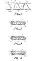
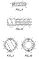
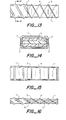
- Figures 1-18 are plan and cross-sectional views of heaters of the invention and Figures 19-22 are cross-sectional views of heatina strips suitable for use in the invention.
- the reference numerals in the Figures denote the same or similar components.
- numerals 1, 2, iA and 2A denote heating strips; 11 denotes a first conductive polymer component of a heating strip; 12 denotes a second conductive polymer component of a heating strip; 13 denotes an insulating component of a heating strip; 14 denotes a multifilament yarn composed of an insulating material; 3, 4, 5 and 5A denote round wire conductors; 6 denotes a separator strip which maintains the conductors in a desired configuration; and 61 denotes a metal conductor embedded in an insulating separator strip; 7 denotes an outer insulating jacket; and 9 denotes a low resistivity conductive material at the junctions of the heating strip and the conductors.
- a single heating strip 1 is wrapped helically around conductors 3 and 4 and separator strip 6. Electrical contact between the heating strip and the conductors is enhanced by means of low resistivity material 9 which forms a fillet between the strip and the conductor at the contact points.
- the separator strip may consist of polymeric insulating material (Figure 2), or comprise a metal conductor embedded in polymeric insulating material (Figure 3), or consist of a conductive polymer composition ( Figures 5 and 6 are very similar to Figures 1 and 2 except that there are two heating strips 1 and 2.
- Figure 7 shows a heater which is suitable for use with a 3-phase power source and which comprises three conductors 3.
- FIGS. 4 and 5 separated by a generally triangular insulating strip 6 and having a heating strip 1 wrapped around them.
- a polymeric insulating jacket 7 which surrounds the heating strip, the conductors and the separator.
- Figure 8 is the same as Figure 1 except that it does not contain a separator strip, the insulating jacket 7 serving to maintain the conductors in the desired configuration.
- Figure 9 is similar to Figure 1 except that the heater strip is wrapped around the separator and the conductors are then brought into contact with the heating strip.
- Figures 10 and 11 show a heater in which heating strips 1, 2, 1A and 2A are spaced around an insulating separator strip 6 and conductors 3 and 4 are wrapped helically around the separator strip and the heating strips.
- Figure 12 shows a heater in which a heating strip 1 is wrapped helically around four conductors 3, 4, 5 and 5A which are supported by a metal pipe 61 which is surrounded by insulating material 6.
- Figures 13 and 14 show a heater in which conductors 3 and 4 are wrapped helically around a core comprising an insulating strip 6 sandwiched between heating strips 1 and 2.
- Figures 15 and 16 show a heater which is the same as that shown in Figures 13 and 14 except that the conductors are wrapped in a Z-configuration so that they cross the heating strips 1 and 2 at riqht angles.
- Figures 17 and 18 show a heater in which a heating strip 1 is laid down in a sinusoidal path on top of conductors 3 and 4.
- Figures 19, 20. 21 and 22 show cross-sections of different heating strips which can be used in the invention.
- Figure 19 shows a strip which is a simple melt-extrudate of a PTC conductive polymer.
- Figure 20 shows a strip which contains a melt-extruded core 12 of a ZTC conductive polymer and a melt-extruded outer layer 11 of a PTC conductive polymer.
- Figure 21 shows a strip which contains an insulating core 13 and a melt-extruded outer layer 11 of a PTC conductive polymer.
- Figure 22 shows a multifilament glass yarn which has been coated, at least on its surface, with a conductive polymer composition, e.g. by passing the yarn through a water or solvent-based composition followed by drying.
- Example 6 the conductive polymer was extruded around a glass fiber yarn which had a diameter of 0.042 cm, and which had previously been coated with a graphite emulsion and dried. The heating strip was then wrapped around a pair of nickel-coated copper conductors of the size shown.
- Example 1 the conductors were first coated with a graphite emulsion and then dried.
- Example 6 the conductors were first coated with a layer 0.034 cm thick of the same composition as was used for the PTC heating strip. The wrapping of the strip was at the pitch shown. In Examples 1-4 and 6, a single strip was wound. In Example 5, two equispaced strips were wound. In Example 1, the conductors were maintained 0.63 cm apart while they were being wrapped. In the other Examples, the strip was wrapped around the conductors and a separator strip. The dimensions and materials of the separator strip are shown in the Table, and it is to be noted that in Examples 3-6, the separator contained an aluminum strip of the dimensions shown, encapsulated with the polymeric separator materials.
- the separator strips had concave ends into which the conductors fitted.
- the junctions between the conductors and the heating strip were coated with graphite emulsion and then dried.
- a polymeric jacket of the material and thickness shown in the Table, was applied by melt-extrusion around the heater.
- the first jacket layer was a mixture of PFA polymer and 5% by weight of glass fibers;
- the second layer (not indicated in the Table) was a tin-coated copper braid (12 end, 34 AWG); the final layer was composed of ETFE.
- the jacket was a mixture of FEP polymer and 10% by weight of glass fibers.
- the ETFE polymer was an ethylene/ tetrafluoroethylene copolymer sold by du Pont under the trade name Tefzel 2010.
- the PFA polymer was a tetrafluoro- ethylene/perfluoroalkoxy copolymer sold by du Pont under the trade name Teflon PFA.
- the FEP polymer was a tetra- fiuoroethylene/hexafiuoropropyiene copolymer sold by du Pont under the trade name Teflon FEP 100.
- the zinc oxide was Kadox 515 available from Gulf and Western.
- Continex N330 is a carbon black available from Cabot.
- Vulcan XC-72 is a carbon black.
- the graphite emulsion was Electrodag 502, available from Acheson Colloids.
Abstract
Description
- This invention relates to elongate electrical strip heaters.
- Many elongate electrical heaters, e.g. for heating pipes, tanks and other apparatus in the chemical process industry, comprise two (or more) relatively low resistance conductors which are connected to the power source and run the length of the heater, with a plurality of heating elements connected in parallel with each other between the conductors (also referred to in the art as electrodes.) In conventional conductive polymer strip heaters, the heating elements are in the form of a continuous strip of conductive polymer in which the conductors are embedded. In other conventional heaters, known as zone heaters, the heating elements are one or more resistive metallic heating wires. In zone heaters, the heatinq wires are wrapped around the conductors, which are insulated except at spaced-apart points where they are connected to the heating wires. The heating wires contact the conductors alternately and make multiple wraps around the conductors between the connection points. For many uses, elongate heaters are preferably self-regulating. This is achieved, in conventional conductive polymer heaters, by using a continuous strip of conductive polymer which exhibits PTC behavior. It has also been proposed to make zone heaters self-regulating by connecting the heating wire(s) to one or both of the conductors through a connecting element composed of a ceramic PTC material.
- Elongate heaters of various kinds, and conductive polymers for use in such heaters, are disclosed in U. S. Patents Nos. 2,952,761, 2,978,665, 3,243,753, 3,351,882, 3,571,777, 3,757,086, 3,793,716, 3,823,217, 3,858,144, 3,861,029, 4,017,715, 4,072,848, 4,085,286, 4,117,312, 4,177,376, 4,177,446, 4,188,276, 4,237,441, 4,242,573, 4,246,468, 4,250,400, 4,255,698, 4,271,350, 4,272,471, 4,309,596, 4,309,597 4,314,230, 4,315,237 4,318,881, 4,327,351, 4,330,704, 4,334,148, 4,334,351 and 4,361,799; J. Applied Polymer Science 19, 813-815 (1975), Klason and Kubat; Polymer Engineering and Science 18, 649-653 (1978), Narkis et al; German OLS Nos. 2,634,999, 2,755,077, 2,746,602, 2,755,076, 2,821,799, and 3,030,799; U.K. Patents No. 1,600,256 and 1,605,005; published European Patent Applications Nos. 0038713, 0038714, 0038718 and 0063440; and the applications filed corresponding to U.S. Serial Nos. 300,709, 369,309, 141,988, 150,909 and 254,352. The disclosure of each of the patents, publications and applications referred to above is incorporated herein by reference.
- This invention relates to improved elongate electrical heaters which comprise
- (1) first and second elongate, spaced-apart, conductors which can be connected to a source of electrical power and
- (2) an elongate resistive heating strip which is in electrical contact alternately with the first conductor and the second conductor at contact points which are longitudinally spaced-apart along the length of the strip and along the length of each of the conductors.
- In one embodiment of the invention, the heating strip comprises an elongate non-metallic resistive heating component, especially an elongate conductive polymer component. Such heaters are distinguished from conventional conductive polymer strip heaters and conductive polymer heaters as disclosed in U.S. U.S. Patents Nos. 4,271,350 and 4,309,597 by the requirement that the contact points are longitudinally spaced apart along the length of the heating strip. This is a difference which can result in very important advantages. One advantage results from the fact that elongate conductive polymer components are generally produced by methods which involve continuously shaping the conductive polymer composition into a strip, eg. by melt-extrusion or by deposition onto a substrate. It has been found that the uniformity of the resistance of such a strip is greater in the longitudinal (or "machine") direction (eg. the direction of extrusion) than in the transverse direction. In the known conductive polymer heaters, current passes through the conductive polymer mainly or exclusively in the transverse direction, whereas in the strip heaters of the invention, the current usually passes through the conductive polymer mainly or exclusively in the longitudinal direction. In consequence the new heaters can have improved power output and voltage stability. Another advantage is that if an arcing fault occurs in a known conductive polymer heater, the fault can be propagated along the whole length of the heater, and thus render the whole heater inoperative. On the other hand, if such a fault occurs in a heater of the invention, it is difficult or impossible for it to propagate along the heater, because there is no continuous interface between the conductive polymer component of the heating strip and the conductors.
- In a second embodiment of the invention, the heater is a self-regulating heater because the heating strip comprises a continuous elongate element which exhibits PTC behavior In this specification a component is said to exhibit PTC behavior if its resistance increases by a factor of at least about 2 over a temperature ranqe of 100°C A more rapid increase in resistance is preferred for example an increase in resistance by a factor of at least 2 5 over a temperature range of 14°C or by a factor of at least 10 over a temperature range of 100°C and preferably both Such heaters are distinguished from known conductive polymer heaters by the requirement for spaced-apart contact points on the strip as just described and from self-regulating zone heaters as disclosed in U S
Patent No 4 117 312 by the fact that the heating strip comprises a continuous elongate element which exhibits PTC behavior whereas inPatent No 4 117 312 it is only the connecting element which exhibits PTC behavior This difference results in important advantages because the use of a small PTC connecting element as described in Patent No- 4 117 312 results in very high power densities in the connecting element with conse- ouent danger of damage to the element or its connections to the bus wire and the heating wire - In a third embodiment of the invention the heating strip (a) has a resistance at 23°C of at least 10 preferably at least 100 ohms per cm length and a cross-sectional area of at least 0 0001 cm2 preferably at least 0 001 cm2 and (b) makes electrical contact with each conductor each time the heating strip crosses the conductor Such heaters are distinguished from known conductive polymer heaters by the requirement for spaced-apart contact points on the strip as just described and from self-regulating zone heaters as disclosed in U S
Patent No 4 117 312 by the resistance and cross-sectional area requirements and the requirement for electrical contact at each crossing point In this way a great disadvantaqe of known zone heaters is avoided namely the necessity for multiple wraps of the heating wire between contact points in order to obtain the necessary level of resistance with the consequent need to insulate the conductors except at the contact points - The three embodiments of the invention are not of course mutually exclusive Thus a preferred class of heaters of the invention comprises a PTC conductive polymer heating strip wrapped around a pair of conductors and making contact with each of the conductors at each wrapping point the heating strip having for example a cross-sectional area of 0 002 to 0 08 cm and a resistance of 100 to 5 000 ohms per cm length Another class of heaters of the invention comprises two or three conductors wrapped around a central element which comprises an elongate PTC conductive polymer heating strip and an elongate insulating element the conductors making contact with the PTC element at each wrapping point the heating strip having for example a cross-sectional area of 0 002 to 0 6 cm and a resistivity at 23°C of 1 to 10 000 ohm cm preferably 1 to 100 ohm cm for heaters to be powered by low voltage sources and 100 to 5 000 ohm cm for heaters to be powered by conventional line voltages
- In addition to the advantages already noted the novel heaters offer the considerable benefit that excellent conductive polymer heaters can be made from polymers which cannot be satisfactorily used in conventional heaters in particular tetrafluorethylene/perfluoroalkoxy polymers whose hiqh melting point makes them particularly valuable Also the absence of a continuous metal/conductive polymer interface renders the heaters less liable to failure in the presence of moisture. Finally, heaters of different powers can easily be made from the same components merely by changing the geometry of the heaters.
- The novel heaters are preferably self-regulating heaters comprising a heating strip which exhibits PTC behavior, particularly a heating strip comprising a component which runs the length of the heatinq strip and which exhibits PTC behavior, when its resistance/temperature characteristic is measured in the absence of the other components of the heater, particularly a heating strip comprising a PTC conductive polymer component. However, the heating strip can also exhibit PTC behavior as a result (at least in part) of constructing and arranging the heater so that, when the heater increases in temperature, the heating strip undergoes a reversible physical change (e.g. elastic stretching due to thermal expansion of part of the heating strip and/or other components of the heater) which increases its resistance. When (as is usually the case) the heater comprises an insulating polymeric jacket, pressure exerted by this jacket can (but usually does not) influence the PTC behavior of the strip.
- There are a wide variety of relative confiqurations of the heating strip(s) and the conductors which will give rise to the desired spaced-apart contact points. Generally it will be convenient for the conductors to be straight and the heatinq strip(s) to follow a regular sinuous path, or vice-versa. The path may be for example generally helical (including generally circular and flattened circular helical) sinusoidal or Z-shaped However it is also possible for both the conductors and the heating strip(s) to follow regular sinuous paths which are different in shape or pitch or of opposite hand or for one or both to follow an irregular sinuous path In one preferred configuration the heating strip is wrapped around a pair of straight parallel conductors which may be maintained the desired distance apart by means of a separator strip In another configuration the heating strip is wrapped around a separator strip and the wrapped strip is then contacted by straight conductors In another preferred configuration the conductors are wrapped around one or more straight heating strips and one or more straight insulating cores the core may be (or contain) the substrate to be heated- eg an insulated metal pipe or a pipe composed of insulating material. In another configuration the conductors'are wrapped around an insulating core and are then contacted by straight heating strips It is often convenient for the wrapped element to have a generally helical configuration such as may be obtained using conventional wire- wrapping apparatus However other wrapped configurations are also possible and can be advantageous in ensuring that substantially all the current passing through the heating strip does so along the axis of the strip for example when the conductors are wrapped around the heating strip(s) they can be wrapped so that their axes. as they cross the heating strip(s) are substantially'at right angles to the axis of the heating strip with the progression of the conductors down the length of the strip being mainly or exclusively achieved while the conductors are not in contact with the heating strip In the various wrapped configurations, the wrapped component can for example follow a path which is generally circular, oval or rectangular with rounded corners. For the best heat transfer to a substrate, it is often preferred that the heater has a shape which is generally rectangular with rounded corners.
- It is also possible tor the heating strip to be laid out, eg. through use of a vibrating extrusion head, in a regular sinuous pattern, either on top of the conductors or on a support, with the conductors then being applied to the laid-out heating strip. If the heating strip is laid out on top of the conductors, further conductors can be placed on top of the original ones, thus sandwiching the heating strip in the middle of a two part conductor.
- The novel heaters generally contain two elongate conductors which are alternately contacted by the heating strip. However, there can be three or more conductors which are sequentially contacted by the heating strip, provided that the conductors are suitably connected to one or more suitable power sources. When three or more conductors are present, they can be arranged so that different power outputs can be obtained by connecting different pairs of conductors to a single phase or two phase power source. When three conductors are present they can be arranged so that the heater is suitable for connection to a three phase power source. The conductors are usually parallel to each other. The conductors are preferably of metal, eg. single or stranded wires, but other materials of low resistivity can be used. The shape of the conductor at the contact points with the heating strip can influence the electrical characteristics of the junctions. Round wire conductors are often convenient and give good results but conductors of other cross-sections (for example flat metal strips) can also be used. The conductors can be contacted by the heating strip directly or through an intermediate conductive component for example the conductors can be coated with a layer of conductive material eg a low resistivity ZTC conductive polymer composition before being contacted by the heating strip.
- The conductors must remain spaced apart from each other. and for this reason the novel heaters preferably comprise at least one separator strip which lies between the conductors The separator strip is preferably one which will remain substantially unchanged during preparation and use of the heater. except for thermal expansion and contraction due to temperature changes such thermal expansion and contraction can be significant in influencing PTC behavior especially when the separator strip comprises a metal insert, particularly when the insert is a conductor which generates heat by I2R heating during use of the heater. as further described below. The separator strip will usually have the same general configuration as the conductors. eg if they are straight- the separator is straight. and if they are wrapped. the separator is wrapped with them
- In one class of heaters the separator strip electrically insulates the conductors from each other so that when the conductors are connected to a power source all the current passing between the conductors passes through the heating strip or strips. Such a separator strip can consist essentially of electrically insulating material. However the properties of the heaters are improved if the separator has good thermal conductivity. and for this reason (since most materials of good thermal conductivity are also electrical conductors) the separator strip can comprise electrically conductive material. eg. metal- surrounded by insulating material. The insulating material is generally a polymeric material. preferably one containing a thermally conductive- material.
- In another class of heaters. the separator strip is composed of electrically resistive material and thus provides an additional source of heat when the conductors are connected to a power source. In this class of heaters. the heater preferably comprises a second resistive heating strip which is composed of a conductive polymer composition and which is in continuous electrical contact with the conductors. The resistance and resistance/ temperature characteristics of such a separator strip can be correlated with those of the heating strip or strips to produce desired results. as further discussed below. In such heaters there will usually be a continuous interface between the conductors and the conductive separator strip and at least a substantial proportion of the current which passes through the separator strip will do so in a transverse direction.
- The conductors can also be maintained in desired positions by means of insulating material which also provides an insulating jacket around the conductors and heating strip or strips. The jacket can for example be in the form of a tube which has been drawn down around a pair of conductors having a heater strip wrapped around them.
- In addition to the conductors which are contacted by the heating strip, the novel heaters can contain one or more additional elongate conductors which are insulated from the other electrical components and which can be used to connect the heater in the novel way disclosed in U.S. application Serial No. 369,309 and optionally to provide an auxiliary source of heat. One or more of such conductors can be embedded in an insulating separator strip.
- The novel heaters contain at least one heatinq strip which contacts the elongate conductors. In many cases, use of a single heating strip gives excellent results. However, two or more heating strips can be used, in which case the heating strips are usually, but not necessarily, parallel to each other along the length of the heater; the heating strips are preferably the same, but can be different; for example, one of the heating strips can be PTC with one T s and another can be ZTC or PTC with a different T . For a particular heating strip, heaters of the same power output can be obtained by a single strip wrapped at a relatively low pitch (a high number of turns per unit length) or by a plurality of parallel heating strips wrapped at a relatively high pitch; use of a plurality of strips results in a lower voltage stress on the heating strip.
- The strip or strips are arranged so that successive contact points on each conductor are spaced apart from each other. If desired, one or more insulatinq members can be wrapped with one or more heating strips so as to maintain desired spacing between adjacent wraps of the heating strip or strips.
- The heating strip can have any configuration which results in the desired alternate contact of the heatinq strip with the conductors. However, excessive bending of the heater strip often has an adverse effect on its electrical and/or physical properties. Consequently it is preferred that the heating strip is in a configuration such that most, and preferably substantially all, of the parts of the heating strip which are electrically active (i.e. which make a useful contribution to the heat output of the heater) are not excessively bent, eg. have a radius of curvature at all points in the substantial current path which is at least 3 times, preferably at least 5 times, especially at least 10 times its diameter.
- The heating strip preferably comprises a conductive polymer component which runs the length of the heating strip, and the invention will be chiefly described by reference to such a strip. However, it is to be understood that the invention includes any kind of resistive heating strip, for example a heating strip which comprises conductive ceramic material, e.g. desposited on single filament or multifilament yarn.
- The heating strip can consist essentially of a single conductive composition, or it can comprise (a) a first component which runs the length of the heating strip and (b) a second component which runs the length of the heating strip and which is composed of a conductive composition, at least a part of the second component lying between the first component and the conductors. The first component can be electrically conducting, eg. be composed of a conductive polymer composition, or electrically insulating, eg. be composed of glass or other ceramic material or natural or synthetic polymeric material. The first and second components are preferably distinct from each other, eg. a first component which provides the core and a second component in the form of a jacket which surrounds the core. However, the second component can also be distributed in a first component which is preferably an electrical insulator, eg. a glass filament yarn which has been passed through a liquid conductive composition eg. a solvent-based composition. When the first and second components are both composed of a conductive polymer composition, the first component is preferably composed of a conductive polymer composition which exhibits PTC behavior with a switching temperature below the switching temperature of the second component.
- An alternative way of providing the desired PTC behavior (or of modifying PTC behavior resulting from use of a PTC heating strip) is to construct the heater so that when the heater increases in temperature, the length of the conductive polymer component of the heating strip is caused to change by an amount different from its normal thermal expansion or contraction. For example the heater can contain conductors or a separator strip comprising a material having a high coefficient of thermal expansion, or the heating strip can comprise a first component composed of a material having a high coefficient of thermal expansion. In this way, for example, a heatinq strip comprising a ZTC conductive polymer component can be caused to exhibit PTC behavior. This is useful because it makes it possible to use ZTC conductive polymer compositions if this is desirable, eg. for particular physical properties. It is of course important that any stretching of the heating strip should be below its elastic limit, and for this reason the heating strip may comprise a first component which is composed of an elastomeric material.
- As briefly noted above. the novel heaters can contain a separator strip which provides a second resistive heating strip. which is composed of a second conductive polymer composition and which is in continuous electrical contact with the conductors. The second conductive polymer composition can exhibit PTC behavior, with a switching temperature which is above or below the switching temperature. TS. of a PTC conductive polymer in the wrapped heating strip. Alternatively the second conductive polymer composition can exhibit ZTC behavior at temperatures below T and can provide a current path between the conductors whose resistance (a) is higher than the resistance of the current path along the first heating strip when the heater is at 23°C and (b) is lower than the resistance of the current path along the first heating strip at an elevated temperature.
- The production of conductive polymer heating strips for use in the present invention can be effected in any convenient way, eq. by melt-extrusion, which is usually preferred, or by passing a substrate through a liquid (eg. solvent-based) conductive polymer composition, followed by coolinq or solvent-removal. When producing the strip by melt-extrusion, the draw-down ratio has an important effect on the electrical properties of the heater. Thus use of higher draw-down ratios generally increases the resistance uniformity of the strip but reduces the extent of any PTC effect. The optimum draw-down ratio depends on the particular conductive polymer composition.
- The thickness of the conductive polymer in the heating strip is preferably 0.025 to 0.2 cm. e.g. 0.06 to 0.14 cm. The strip can be of round or other cross- section: for example the heater strip can be in the form of a flat tape.
- The conductive polymer heating strips can optionally be cross-linked, eg. by irradiation. either before or after they are assembled into heaters.
- A very.wide variety of conductive polymers can be used in the heating strips, for example compositions based on polyolefins. copolymers of olefins and polar comonomers, fluoropolymers and elastomers, as well as mixtures of two or more of these. Suitable conductive polymers are disclosed in the publications referenced above. The resistivity of such conductive polymers at 23°C is usually 1-100.000, preferably 100 to 5.000. particularly 200 to 3.000, ohm.cm. The conductive polymer can be PTC or ZTC. the term ZTC being used to mean that the conductive polymer does not exhibit PTC behavior in the normal temperature range of operation of the heater (i.e. including NTC behavior).
- The novel heaters are preferably made by wrapping the heating strip (or strips) around the conductors, or vice versa, while maintaining the conductors the desired distance apart, either through use of a separator strip or otherwise. When using a PTC heating strip, care should be taken to make use of a wrapping tension which provides a suitable compromise between the desire to bring the heating strip into good contact with the conductors and the desire to avoid stretching the strip, which usually causes undesirable changes in its resistance and/or resistance/temperature characteristics. It is preferred to coat the junctions between the conductors and the heating strip with a low resistivity (preferably less than 1 ohm.cm) composition, e.g. a conductive polymer composition (eg. a solvent-based composition which is allowed to dry after it has been applied), so as to reduce contact resistance. Such a coating can also help to ensure that substantially all the current passes only through the substantially straight portions of the heating strip. Care should be taken, however, to ensure that the coating does not extend any substantial distance up the heating strip beyond the junctions, since this reduces the effective (heat-generatinq) length of the heating strip. Similar low resistance coatings can be applied to the contact points by other methods, eg. by flame-spraying or vapor deposition of a metal.
- Other methods which can be used to reduce contact resistance include pre-heating the conductors before they are contacted by the heating strip, and heat-treatinc conductive polymer adjacent the conductors after the heater has been assembled. The whole heater can be heated or localized heating can be effected eg. by powering the conductors.
- A particular advantage of the present invention is that heaters having different electrical characteristics can be easily produced from a single heating strip. For example, a range of very different heaters, eq. of different power outputs, can easily be produced merely by changing the pitch used to wrap the heating strip or the conductors, and/or by using two or more heating strips, and/or by changing the distance between the conductors. The pitch of the heating strip is preferably 0.20 to 2.5 cm and the distance between the conductors is preferably 0.5 to 1.5 cm. These different variables can be maintained substantially constant or one or more of them can be varied periodically to produce a heater having segments of different power outputs. Further, if desired, the pitch of the wrapped component and/or the distance between the conductors can be varied gradually to compensate for changes in the potential difference between the conductors at different distances from the power source.
- In assembling the novel heaters, the presence of voids is preferably avoided, and a polysiloxane grease or other thermal conductor can be used to fill any voids.
- Referring now to the drawing, Figures 1-18 are plan and cross-sectional views of heaters of the invention and Figures 19-22 are cross-sectional views of heatina strips suitable for use in the invention. The reference numerals in the Figures denote the same or similar components. Thus
numerals 1, 2, iA and 2A denote heating strips; 11 denotes a first conductive polymer component of a heating strip; 12 denotes a second conductive polymer component of a heating strip; 13 denotes an insulating component of a heating strip; 14 denotes a multifilament yarn composed of an insulating material; 3, 4, 5 and 5A denote round wire conductors; 6 denotes a separator strip which maintains the conductors in a desired configuration; and 61 denotes a metal conductor embedded in an insulating separator strip; 7 denotes an outer insulating jacket; and 9 denotes a low resistivity conductive material at the junctions of the heating strip and the conductors. - Referring now to Figures 1-4, a single heating strip 1 is wrapped helically around
conductors separator strip 6. Electrical contact between the heating strip and the conductors is enhanced by means oflow resistivity material 9 which forms a fillet between the strip and the conductor at the contact points. The separator strip may consist of polymeric insulating material (Figure 2), or comprise a metal conductor embedded in polymeric insulating material (Figure 3), or consist of a conductive polymer composition (Figure 4). Figures 5 and 6 are very similar to Figures 1 and 2 except that there are twoheating strips 1 and 2. Figure 7 shows a heater which is suitable for use with a 3-phase power source and which comprises threeconductors 3. 4 and 5 separated by a generally triangularinsulating strip 6 and having a heating strip 1 wrapped around them. In each of Figures 1-7 there is a polymeric insulatingjacket 7 which surrounds the heating strip, the conductors and the separator. Figure 8 is the same as Figure 1 except that it does not contain a separator strip, the insulatingjacket 7 serving to maintain the conductors in the desired configuration. Figure 9 is similar to Figure 1 except that the heater strip is wrapped around the separator and the conductors are then brought into contact with the heating strip. Figures 10 and 11 show a heater in which heating strips 1, 2, 1A and 2A are spaced around an insulatingseparator strip 6 andconductors - Figure 12 shows a heater in which a heating strip 1 is wrapped helically around four
conductors metal pipe 61 which is surrounded by insulatingmaterial 6. Figures 13 and 14 show a heater in whichconductors strip 6 sandwiched betweenheating strips 1 and 2. Figures 15 and 16 show a heater which is the same as that shown in Figures 13 and 14 except that the conductors are wrapped in a Z-configuration so that they cross the heating strips 1 and 2 at riqht angles. Figures 17 and 18 show a heater in which a heating strip 1 is laid down in a sinusoidal path on top ofconductors - Figures 19, 20. 21 and 22 show cross-sections of different heating strips which can be used in the invention. Figure 19 shows a strip which is a simple melt-extrudate of a PTC conductive polymer. Figure 20 shows a strip which contains a melt-extruded
core 12 of a ZTC conductive polymer and a melt-extruded outer layer 11 of a PTC conductive polymer. Figure 21 shows a strip which contains an insulatingcore 13 and a melt-extruded outer layer 11 of a PTC conductive polymer. Figure 22 shows a multifilament glass yarn which has been coated, at least on its surface, with a conductive polymer composition, e.g. by passing the yarn through a water or solvent-based composition followed by drying. - The invention is illustrated in the followina Examples, which are summarized in the Table below. In each Example, the ingredients and parts by weight thereof listed in the Table were dry-blended, melt-extruded through a twin screw extruder and chopped into pellets. The pellets were melt-extruded through a Brabender extruder fitted with a die of the diameter shown in the Table, and the extrudate was drawn down to the extent necessary to give a PTC heating strip of the diameter shown. In Example 6, the conductive polymer was extruded around a glass fiber yarn which had a diameter of 0.042 cm, and which had previously been coated with a graphite emulsion and dried. The heating strip was then wrapped around a pair of nickel-coated copper conductors of the size shown. In Example 1, the conductors were first coated with a graphite emulsion and then dried. In Example 6, the conductors were first coated with a layer 0.034 cm thick of the same composition as was used for the PTC heating strip. The wrapping of the strip was at the pitch shown. In Examples 1-4 and 6, a single strip was wound. In Example 5, two equispaced strips were wound. In Example 1, the conductors were maintained 0.63 cm apart while they were being wrapped. In the other Examples, the strip was wrapped around the conductors and a separator strip. The dimensions and materials of the separator strip are shown in the Table, and it is to be noted that in Examples 3-6, the separator contained an aluminum strip of the dimensions shown, encapsulated with the polymeric separator materials. The separator strips had concave ends into which the conductors fitted. In Examples 2-6, the junctions between the conductors and the heating strip were coated with graphite emulsion and then dried. Finally, a polymeric jacket, of the material and thickness shown in the Table, was applied by melt-extrusion around the heater. In Examples 2-4, the first jacket layer was a mixture of PFA polymer and 5% by weight of glass fibers; the second layer (not indicated in the Table) was a tin-coated copper braid (12 end, 34 AWG); the final layer was composed of ETFE. In Example 6, the jacket was a mixture of FEP polymer and 10% by weight of glass fibers. The various ingredients used in the Table and referred to above are further identified below. The ETFE polymer was an ethylene/ tetrafluoroethylene copolymer sold by du Pont under the trade name Tefzel 2010. The PFA polymer was a tetrafluoro- ethylene/perfluoroalkoxy copolymer sold by du Pont under the trade name Teflon PFA. The FEP polymer was a tetra- fiuoroethylene/hexafiuoropropyiene copolymer sold by du Pont under the trade name Teflon FEP 100. The zinc oxide was Kadox 515 available from Gulf and Western. Continex N330 is a carbon black available from Cabot. Vulcan XC-72 is a carbon black. The graphite emulsion was Electrodag 502, available from Acheson Colloids.

Claims (10)
said strip heater exhibiting PTC behavior when the conductors are connected to a source of electrical power to cause heating of said resistive heating strip.
Priority Applications (1)
| Application Number | Priority Date | Filing Date | Title |
|---|---|---|---|
| AT83302884T ATE30825T1 (en) | 1982-05-21 | 1983-05-19 | EXTENDED ELECTRIC HEATING ELEMENTS. |
Applications Claiming Priority (2)
| Application Number | Priority Date | Filing Date | Title |
|---|---|---|---|
| US380400 | 1982-05-21 | ||
| US06/380,400 US4459473A (en) | 1982-05-21 | 1982-05-21 | Self-regulating heaters |
Publications (2)
| Publication Number | Publication Date |
|---|---|
| EP0096492A1 true EP0096492A1 (en) | 1983-12-21 |
| EP0096492B1 EP0096492B1 (en) | 1987-11-11 |
Family
ID=23501027
Family Applications (1)
| Application Number | Title | Priority Date | Filing Date |
|---|---|---|---|
| EP83302884A Expired EP0096492B1 (en) | 1982-05-21 | 1983-05-19 | Elongate electrical heaters |
Country Status (16)
| Country | Link |
|---|---|
| US (1) | US4459473A (en) |
| EP (1) | EP0096492B1 (en) |
| JP (1) | JPH067509B2 (en) |
| KR (1) | KR910000829B1 (en) |
| AT (1) | ATE30825T1 (en) |
| AU (1) | AU555857B2 (en) |
| CA (1) | CA1208268A (en) |
| DE (1) | DE3374515D1 (en) |
| DK (1) | DK157648C (en) |
| ES (1) | ES281130Y (en) |
| FI (1) | FI75464C (en) |
| GB (1) | GB2120909B (en) |
| HK (1) | HK83589A (en) |
| MX (1) | MX158292A (en) |
| MY (1) | MY103947A (en) |
| NO (1) | NO154180C (en) |
Cited By (8)
| Publication number | Priority date | Publication date | Assignee | Title |
|---|---|---|---|---|
| EP0175453A1 (en) * | 1984-07-19 | 1986-03-26 | RAYCHEM CORPORATION (a Delaware corporation) | Modular electrical heater |
| EP0202896A2 (en) * | 1985-05-17 | 1986-11-26 | RAYCHEM CORPORATION (a Delaware corporation) | Electrical sheet heaters |
| FR2593014A1 (en) * | 1986-01-16 | 1987-07-17 | Pyrotenax Canada Ltd | ELECTRIC CABLES AND PREFORMS TO MAKE THESE CABLES |
| WO1990003091A1 (en) * | 1988-09-02 | 1990-03-22 | Monette Kabel- Und Elektrowerk Gmbh | Parallel electric band heater |
| WO1998001010A1 (en) * | 1996-06-28 | 1998-01-08 | Raychem Corporation | Heating cable |
| WO2010032017A1 (en) | 2008-09-18 | 2010-03-25 | Heat Trace Limited | Heating cable |
| DE202015105640U1 (en) * | 2015-10-23 | 2017-01-24 | Rehau Ag + Co | media line |
| RU2708231C1 (en) * | 2019-01-29 | 2019-12-05 | Аньхуэй Хуанжуй Хитинг Мануфэкчуринг Ко., Лтд. | Three-layer co-extruded heating cable and plant for its production |
Families Citing this family (53)
| Publication number | Priority date | Publication date | Assignee | Title |
|---|---|---|---|---|
| US4845343A (en) * | 1983-11-17 | 1989-07-04 | Raychem Corporation | Electrical devices comprising fabrics |
| US5089688A (en) * | 1984-07-10 | 1992-02-18 | Raychem Corporation | Composite circuit protection devices |
| US5148005A (en) * | 1984-07-10 | 1992-09-15 | Raychem Corporation | Composite circuit protection devices |
| US5064997A (en) * | 1984-07-10 | 1991-11-12 | Raychem Corporation | Composite circuit protection devices |
| US4661687A (en) * | 1984-07-11 | 1987-04-28 | Raychem Corporation | Method and apparatus for converting a fluid tracing system into an electrical tracing system |
| US4668857A (en) * | 1985-08-16 | 1987-05-26 | Belton Corporation | Temperature self-regulating resistive heating element |
| US4689475A (en) * | 1985-10-15 | 1987-08-25 | Raychem Corporation | Electrical devices containing conductive polymers |
| US4801785A (en) * | 1986-01-14 | 1989-01-31 | Raychem Corporation | Electrical devices |
| DK87287A (en) | 1986-02-20 | 1987-08-21 | Raychem Corp | METHOD AND APPARATUS FOR USING ION EXCHANGE MATERIAL |
| GB2194719B (en) * | 1986-08-19 | 1990-08-29 | Mohan Singh Boyal | Electrical heating cable |
| JPS6361799U (en) * | 1986-10-14 | 1988-04-23 | ||
| US4733059A (en) * | 1987-06-15 | 1988-03-22 | Thermon Manufacturing Company | Elongated parallel, constant wattage heating cable |
| US4967057A (en) * | 1988-08-02 | 1990-10-30 | Bayless Ronald E | Snow melting heater mats |
| US4885457A (en) * | 1988-09-30 | 1989-12-05 | Raychem Corporation | Method of making a conductive polymer sheet |
| GB2225691A (en) * | 1988-12-02 | 1990-06-06 | Electric Surface Heating Ltd | Parallel circuit heating cable |
| US5111032A (en) * | 1989-03-13 | 1992-05-05 | Raychem Corporation | Method of making an electrical device comprising a conductive polymer |
| US5052699A (en) * | 1989-07-10 | 1991-10-01 | Raychem Corporation | Grommet |
| US5925276A (en) * | 1989-09-08 | 1999-07-20 | Raychem Corporation | Conductive polymer device with fuse capable of arc suppression |
| CA1338315C (en) * | 1989-09-22 | 1996-05-07 | Glenwood Franklin Heizer | Cut to length heater cable |
| US5004432A (en) * | 1989-10-02 | 1991-04-02 | Raychem Corporation | Electrical connector |
| US5045673A (en) * | 1990-04-04 | 1991-09-03 | General Signal Corporation | PTC devices and their composition |
| KR100245568B1 (en) * | 1990-05-07 | 2000-02-15 | 허버트 지. 버카드 | Electrical device |
| JPH04272680A (en) * | 1990-09-20 | 1992-09-29 | Thermon Mfg Co | Switch-controlled-zone type heating cable and assembling method thereof |
| US6111234A (en) * | 1991-05-07 | 2000-08-29 | Batliwalla; Neville S. | Electrical device |
| US5317061A (en) * | 1993-02-24 | 1994-05-31 | Raychem Corporation | Fluoropolymer compositions |
| US5432323A (en) * | 1994-01-07 | 1995-07-11 | Sopory; Umesh K. | Regulated electric strip heater |
| US5552199A (en) * | 1994-09-02 | 1996-09-03 | Minnesota Mining And Manufacturing Company | Melt-processable electroconductive fluoroplastic |
| US5756972A (en) * | 1994-10-25 | 1998-05-26 | Raychem Corporation | Hinged connector for heating cables of various sizes |
| US5550350A (en) * | 1994-11-17 | 1996-08-27 | Donald W. Barnes | Heated ice-melting blocks for steps |
| US5622642A (en) * | 1995-02-06 | 1997-04-22 | Raychem Corporation | Sealing apparatus for elongate cables having movable insert with gripping members |
| US5792987A (en) * | 1995-08-28 | 1998-08-11 | Raychem Corporation | Sealing device |
| US5718600A (en) * | 1996-01-17 | 1998-02-17 | Raychem Corporation | Electrical plug |
| US5767448A (en) * | 1996-09-30 | 1998-06-16 | Raychem Corporation | Sealing device |
| EP1121728B1 (en) | 1998-10-15 | 2005-11-09 | TYCO Electronics Corporation | Connector for electrical cable |
| US6288372B1 (en) * | 1999-11-03 | 2001-09-11 | Tyco Electronics Corporation | Electric cable having braidless polymeric ground plane providing fault detection |
| US7588029B2 (en) * | 2000-03-21 | 2009-09-15 | Fisher & Paykel Healthcare Limited | Humidified gases delivery apparatus |
| US7111624B2 (en) | 2000-03-21 | 2006-09-26 | Fisher & Paykel Healthcare Limited | Apparatus for delivering humidified gases |
| EP1326665B1 (en) * | 2000-10-16 | 2019-05-08 | Fisher & Paykel Healthcare Limited | Apparatus used for the humidification of gases in medical procedures |
| US6597551B2 (en) | 2000-12-13 | 2003-07-22 | Huladyne Corporation | Polymer current limiting device and method of manufacture |
| GB2390004A (en) * | 2002-03-08 | 2003-12-24 | Martin Cook | Flexible heating element |
| ITVE20020012A1 (en) * | 2002-03-13 | 2003-09-15 | Alper Srl | ELECTRIC DEANANT OR INSECTICIDE EMANATOR. |
| GB0216932D0 (en) * | 2002-07-20 | 2002-08-28 | Heat Trace Ltd | Electrical heating cable |
| FR2851116B1 (en) * | 2003-02-07 | 2008-01-18 | Atofina | PTC-COATED TEMPERATURE RESISTANCE HEATING WIRE, CONTAINING THE SAME AND APPLICATIONS THEREOF |
| PL4049703T3 (en) | 2004-08-20 | 2024-03-04 | Fisher & Paykel Healthcare Limited | Apparatus for measuring properties of gases supplied to a patient |
| US20110068098A1 (en) * | 2006-12-22 | 2011-03-24 | Taiwan Textile Research Institute | Electric Heating Yarns, Methods for Manufacturing the Same and Application Thereof |
| US8212191B2 (en) * | 2008-05-16 | 2012-07-03 | Thermon Manufacturing Co. | Heating cable with a heating element positioned in the middle of bus wires |
| JP5444886B2 (en) * | 2009-06-30 | 2014-03-19 | トヨタ紡織株式会社 | Skin material for vehicle seats |
| US8294066B2 (en) * | 2010-11-19 | 2012-10-23 | Eaton Corporation | Thermally and electrically conductive element |
| US9403538B2 (en) * | 2012-08-16 | 2016-08-02 | Messiah Locomotive Service, Inc. | Efficient sand tub heater |
| WO2017142955A1 (en) * | 2016-02-15 | 2017-08-24 | Pentair Thermal Management Llc | Flexible small-diameter self-regulating heater cable |
| US10470251B2 (en) | 2016-04-29 | 2019-11-05 | Nvent Services Gmbh | Voltage-leveling monolithic self-regulating heater cable |
| US10932326B2 (en) | 2018-05-24 | 2021-02-23 | Goodrich Aerospace Services Private Limited | Flexible heated hose assembly with printed positive temperature co-efficient heater |
| WO2020260951A1 (en) * | 2019-06-26 | 2020-12-30 | Nvent Services Gmbh | Self-regulating heater cable with buffer layer |
Citations (5)
| Publication number | Priority date | Publication date | Assignee | Title |
|---|---|---|---|---|
| CH468704A (en) * | 1963-03-05 | 1969-02-15 | Elofol Ag | Electrical resistance material |
| DE2614433A1 (en) * | 1975-04-07 | 1976-10-14 | Philips Nv | SELF-REGULATING HEATING ELEMENT |
| DE2634999A1 (en) * | 1975-08-04 | 1977-02-10 | Raychem Corp | IMPROVED PTC DIMENSIONS, METHODS OF MANUFACTURING IT, AND USING IT AS A HEATING RAND |
| US4072848A (en) * | 1976-07-22 | 1978-02-07 | Thermon Manufacturing Company | Electrical heating cable with temperature self-limiting heating elements |
| US4271350A (en) * | 1980-05-19 | 1981-06-02 | Sunbeam Corporation | Blanket wire utilizing positive temperature coefficient resistance heater |
Family Cites Families (20)
| Publication number | Priority date | Publication date | Assignee | Title |
|---|---|---|---|---|
| US2575987A (en) * | 1947-08-29 | 1951-11-20 | Rca Corp | Conducting rubber heating element |
| US2719907A (en) * | 1952-04-19 | 1955-10-04 | Connecticut Hard Rubber Co | Heating tape and method of making same |
| JPS4115076Y1 (en) * | 1965-10-02 | 1966-07-14 | ||
| GB1167551A (en) * | 1965-12-01 | 1969-10-15 | Texas Instruments Inc | Heaters and Methods of Making Same |
| US3410984A (en) * | 1966-05-03 | 1968-11-12 | Gen Electric | Flexible electrically heated personal warming device |
| US3441893A (en) * | 1966-12-28 | 1969-04-29 | Gen Electric | Resistance temperature detector |
| JPS5230896Y2 (en) * | 1971-08-20 | 1977-07-14 | ||
| US3781528A (en) * | 1972-05-30 | 1973-12-25 | Bulten Kanthal Ab | Heat resistant,electrical insulating heating unit |
| US3861029A (en) * | 1972-09-08 | 1975-01-21 | Raychem Corp | Method of making heater cable |
| US3757086A (en) * | 1972-10-05 | 1973-09-04 | W Indoe | Electrical heating cable |
| US4017715A (en) * | 1975-08-04 | 1977-04-12 | Raychem Corporation | Temperature overshoot heater |
| US4330703A (en) * | 1975-08-04 | 1982-05-18 | Raychem Corporation | Layered self-regulating heating article |
| JPS5230728A (en) * | 1975-09-05 | 1977-03-08 | Nippon Steel Corp | Production method of zinc plated steel plate |
| JPS52119146U (en) * | 1976-03-09 | 1977-09-09 | ||
| US4100673A (en) * | 1977-05-05 | 1978-07-18 | Leavines Joseph E | Method of making high temperature parallel resistance pipe heater |
| JPS5461663A (en) * | 1977-10-05 | 1979-05-18 | Ford Motor Co | Encapsuled titania thermistor and its preparation |
| US4276466A (en) * | 1979-05-11 | 1981-06-30 | Raychem Corporation | Heater with distributed heating element |
| US4250400A (en) * | 1979-11-19 | 1981-02-10 | The Scott & Fetzer Company | Flexible temperature self regulating heating cable |
| US4309597A (en) * | 1980-05-19 | 1982-01-05 | Sunbeam Corporation | Blanket wire utilizing positive temperature coefficient resistance heater |
| DE3147995A1 (en) * | 1981-12-04 | 1983-06-16 | Heraeus-Wittmann Gmbh, 6450 Hanau | "ELECTRIC HEATING RIBBON" |
-
1982
- 1982-05-21 US US06/380,400 patent/US4459473A/en not_active Expired - Lifetime
-
1983
- 1983-05-17 AU AU14594/83A patent/AU555857B2/en not_active Ceased
- 1983-05-18 ES ES1983281130U patent/ES281130Y/en not_active Expired
- 1983-05-19 AT AT83302884T patent/ATE30825T1/en not_active IP Right Cessation
- 1983-05-19 DE DE8383302884T patent/DE3374515D1/en not_active Expired
- 1983-05-19 EP EP83302884A patent/EP0096492B1/en not_active Expired
- 1983-05-19 GB GB08313833A patent/GB2120909B/en not_active Expired
- 1983-05-20 CA CA000428564A patent/CA1208268A/en not_active Expired
- 1983-05-20 FI FI831812A patent/FI75464C/en not_active IP Right Cessation
- 1983-05-20 DK DK228483A patent/DK157648C/en not_active IP Right Cessation
- 1983-05-20 NO NO831815A patent/NO154180C/en not_active IP Right Cessation
- 1983-05-20 MX MX197366A patent/MX158292A/en unknown
- 1983-05-21 JP JP58089899A patent/JPH067509B2/en not_active Expired - Lifetime
- 1983-05-21 KR KR1019830002233A patent/KR910000829B1/en not_active IP Right Cessation
-
1988
- 1988-12-22 MY MYPI88001515A patent/MY103947A/en unknown
-
1989
- 1989-10-19 HK HK835/89A patent/HK83589A/en not_active IP Right Cessation
Patent Citations (6)
| Publication number | Priority date | Publication date | Assignee | Title |
|---|---|---|---|---|
| CH468704A (en) * | 1963-03-05 | 1969-02-15 | Elofol Ag | Electrical resistance material |
| DE2614433A1 (en) * | 1975-04-07 | 1976-10-14 | Philips Nv | SELF-REGULATING HEATING ELEMENT |
| DE2634999A1 (en) * | 1975-08-04 | 1977-02-10 | Raychem Corp | IMPROVED PTC DIMENSIONS, METHODS OF MANUFACTURING IT, AND USING IT AS A HEATING RAND |
| US4072848A (en) * | 1976-07-22 | 1978-02-07 | Thermon Manufacturing Company | Electrical heating cable with temperature self-limiting heating elements |
| US4117312A (en) * | 1976-07-22 | 1978-09-26 | Thermon Manufacturing Company | Self-limiting temperature electrical heating cable |
| US4271350A (en) * | 1980-05-19 | 1981-06-02 | Sunbeam Corporation | Blanket wire utilizing positive temperature coefficient resistance heater |
Cited By (12)
| Publication number | Priority date | Publication date | Assignee | Title |
|---|---|---|---|---|
| EP0175453A1 (en) * | 1984-07-19 | 1986-03-26 | RAYCHEM CORPORATION (a Delaware corporation) | Modular electrical heater |
| EP0202896A2 (en) * | 1985-05-17 | 1986-11-26 | RAYCHEM CORPORATION (a Delaware corporation) | Electrical sheet heaters |
| EP0202896B1 (en) * | 1985-05-17 | 1991-09-04 | RAYCHEM CORPORATION (a Delaware corporation) | Electrical sheet heaters |
| FR2593014A1 (en) * | 1986-01-16 | 1987-07-17 | Pyrotenax Canada Ltd | ELECTRIC CABLES AND PREFORMS TO MAKE THESE CABLES |
| WO1990003091A1 (en) * | 1988-09-02 | 1990-03-22 | Monette Kabel- Und Elektrowerk Gmbh | Parallel electric band heater |
| WO1998001010A1 (en) * | 1996-06-28 | 1998-01-08 | Raychem Corporation | Heating cable |
| US6005232A (en) * | 1996-06-28 | 1999-12-21 | Raychem Corporation | Heating cable |
| WO2010032017A1 (en) | 2008-09-18 | 2010-03-25 | Heat Trace Limited | Heating cable |
| CN102160457B (en) * | 2008-09-18 | 2014-09-03 | 电伴热有限公司 | Heating cable |
| US8952300B2 (en) | 2008-09-18 | 2015-02-10 | Heat Trace Limited | Heating cable |
| DE202015105640U1 (en) * | 2015-10-23 | 2017-01-24 | Rehau Ag + Co | media line |
| RU2708231C1 (en) * | 2019-01-29 | 2019-12-05 | Аньхуэй Хуанжуй Хитинг Мануфэкчуринг Ко., Лтд. | Three-layer co-extruded heating cable and plant for its production |
Also Published As
| Publication number | Publication date |
|---|---|
| AU1459483A (en) | 1983-11-24 |
| DK157648B (en) | 1990-01-29 |
| US4459473A (en) | 1984-07-10 |
| MY103947A (en) | 1993-10-30 |
| ES281130U (en) | 1985-10-16 |
| FI831812A0 (en) | 1983-05-20 |
| NO831815L (en) | 1983-11-22 |
| NO154180B (en) | 1986-04-21 |
| FI75464C (en) | 1988-06-09 |
| FI831812L (en) | 1983-11-22 |
| EP0096492B1 (en) | 1987-11-11 |
| ES281130Y (en) | 1986-05-16 |
| GB2120909B (en) | 1986-02-19 |
| MX158292A (en) | 1989-01-20 |
| CA1208268A (en) | 1986-07-22 |
| JPH067509B2 (en) | 1994-01-26 |
| KR910000829B1 (en) | 1991-02-09 |
| GB8313833D0 (en) | 1983-06-22 |
| DE3374515D1 (en) | 1987-12-17 |
| GB2120909A (en) | 1983-12-07 |
| ATE30825T1 (en) | 1987-11-15 |
| FI75464B (en) | 1988-02-29 |
| DK228483D0 (en) | 1983-05-20 |
| AU555857B2 (en) | 1986-10-09 |
| NO154180C (en) | 1986-08-06 |
| DK228483A (en) | 1983-11-22 |
| HK83589A (en) | 1989-10-27 |
| DK157648C (en) | 1990-07-02 |
| KR840004655A (en) | 1984-10-22 |
| JPS58214295A (en) | 1983-12-13 |
Similar Documents
| Publication | Publication Date | Title |
|---|---|---|
| EP0096492B1 (en) | Elongate electrical heaters | |
| US4922083A (en) | Flexible, elongated positive temperature coefficient heating assembly and method | |
| US4271350A (en) | Blanket wire utilizing positive temperature coefficient resistance heater | |
| US4309597A (en) | Blanket wire utilizing positive temperature coefficient resistance heater | |
| CA2260189C (en) | Heating cable | |
| US4037083A (en) | High temperature parallel resistance pipe heater | |
| NZ196936A (en) | Heating cable: fibre core carbon impregnated | |
| EP0475458B1 (en) | Elongated parallel, constant wattage heating cable | |
| RU2358416C2 (en) | Self-regulating electrical heating cable | |
| EP0287898B1 (en) | Flexible, elongated thermistor heating cable | |
| US4308448A (en) | Heating cable with a specific heating capacity | |
| JPH0526316B2 (en) | ||
| GB2236236A (en) | Electric heating cable | |
| EP0930804B1 (en) | Heating cable | |
| CA2098154C (en) | Heating cable | |
| KR100497692B1 (en) | Heating cable | |
| KR20170097406A (en) | Heating cable enhancing available effective length | |
| JPH044590A (en) | Self temp controlling heat emitting element |
Legal Events
| Date | Code | Title | Description |
|---|---|---|---|
| PUAI | Public reference made under article 153(3) epc to a published international application that has entered the european phase |
Free format text: ORIGINAL CODE: 0009012 |
|
| 17P | Request for examination filed |
Effective date: 19830610 |
|
| AK | Designated contracting states |
Designated state(s): AT BE CH DE FR IT LI NL SE |
|
| GRAA | (expected) grant |
Free format text: ORIGINAL CODE: 0009210 |
|
| AK | Designated contracting states |
Kind code of ref document: B1 Designated state(s): AT BE CH DE FR IT LI NL SE |
|
| PG25 | Lapsed in a contracting state [announced via postgrant information from national office to epo] |
Ref country code: AT Effective date: 19871111 |
|
| REF | Corresponds to: |
Ref document number: 30825 Country of ref document: AT Date of ref document: 19871115 Kind code of ref document: T |
|
| REF | Corresponds to: |
Ref document number: 3374515 Country of ref document: DE Date of ref document: 19871217 |
|
| ITF | It: translation for a ep patent filed |
Owner name: MODIANO & ASSOCIATI S.R.L. |
|
| ET | Fr: translation filed | ||
| PLBE | No opposition filed within time limit |
Free format text: ORIGINAL CODE: 0009261 |
|
| STAA | Information on the status of an ep patent application or granted ep patent |
Free format text: STATUS: NO OPPOSITION FILED WITHIN TIME LIMIT |
|
| 26N | No opposition filed | ||
| ITTA | It: last paid annual fee | ||
| EAL | Se: european patent in force in sweden |
Ref document number: 83302884.8 |
|
| PGFP | Annual fee paid to national office [announced via postgrant information from national office to epo] |
Ref country code: SE Payment date: 20010417 Year of fee payment: 19 |
|
| PGFP | Annual fee paid to national office [announced via postgrant information from national office to epo] |
Ref country code: CH Payment date: 20010511 Year of fee payment: 19 |
|
| PGFP | Annual fee paid to national office [announced via postgrant information from national office to epo] |
Ref country code: DE Payment date: 20010514 Year of fee payment: 19 |
|
| PGFP | Annual fee paid to national office [announced via postgrant information from national office to epo] |
Ref country code: FR Payment date: 20010518 Year of fee payment: 19 |
|
| PGFP | Annual fee paid to national office [announced via postgrant information from national office to epo] |
Ref country code: NL Payment date: 20010531 Year of fee payment: 19 |
|
| PGFP | Annual fee paid to national office [announced via postgrant information from national office to epo] |
Ref country code: BE Payment date: 20010717 Year of fee payment: 19 |
|
| PG25 | Lapsed in a contracting state [announced via postgrant information from national office to epo] |
Ref country code: SE Free format text: LAPSE BECAUSE OF NON-PAYMENT OF DUE FEES Effective date: 20020520 |
|
| PG25 | Lapsed in a contracting state [announced via postgrant information from national office to epo] |
Ref country code: LI Free format text: LAPSE BECAUSE OF NON-PAYMENT OF DUE FEES Effective date: 20020531 Ref country code: CH Free format text: LAPSE BECAUSE OF NON-PAYMENT OF DUE FEES Effective date: 20020531 Ref country code: BE Free format text: LAPSE BECAUSE OF NON-PAYMENT OF DUE FEES Effective date: 20020531 |
|
| PG25 | Lapsed in a contracting state [announced via postgrant information from national office to epo] |
Ref country code: NL Free format text: LAPSE BECAUSE OF NON-PAYMENT OF DUE FEES Effective date: 20021201 |
|
| PG25 | Lapsed in a contracting state [announced via postgrant information from national office to epo] |
Ref country code: DE Free format text: LAPSE BECAUSE OF NON-PAYMENT OF DUE FEES Effective date: 20021203 |
|
| EUG | Se: european patent has lapsed | ||
| REG | Reference to a national code |
Ref country code: CH Ref legal event code: PL |
|
| PG25 | Lapsed in a contracting state [announced via postgrant information from national office to epo] |
Ref country code: FR Free format text: LAPSE BECAUSE OF NON-PAYMENT OF DUE FEES Effective date: 20030131 |
|
| NLV4 | Nl: lapsed or anulled due to non-payment of the annual fee |
Effective date: 20021201 |
|
| REG | Reference to a national code |
Ref country code: FR Ref legal event code: ST |