EP0096373A1 - Adjustable support for CRT keyboard - Google Patents
Adjustable support for CRT keyboard Download PDFInfo
- Publication number
- EP0096373A1 EP0096373A1 EP83105470A EP83105470A EP0096373A1 EP 0096373 A1 EP0096373 A1 EP 0096373A1 EP 83105470 A EP83105470 A EP 83105470A EP 83105470 A EP83105470 A EP 83105470A EP 0096373 A1 EP0096373 A1 EP 0096373A1
- Authority
- EP
- European Patent Office
- Prior art keywords
- support
- primary
- auxiliary
- work surface
- linkage
- Prior art date
- Legal status (The legal status is an assumption and is not a legal conclusion. Google has not performed a legal analysis and makes no representation as to the accuracy of the status listed.)
- Granted
Links
Images


Classifications
-
- F—MECHANICAL ENGINEERING; LIGHTING; HEATING; WEAPONS; BLASTING
- F16—ENGINEERING ELEMENTS AND UNITS; GENERAL MEASURES FOR PRODUCING AND MAINTAINING EFFECTIVE FUNCTIONING OF MACHINES OR INSTALLATIONS; THERMAL INSULATION IN GENERAL
- F16M—FRAMES, CASINGS OR BEDS OF ENGINES, MACHINES OR APPARATUS, NOT SPECIFIC TO ENGINES, MACHINES OR APPARATUS PROVIDED FOR ELSEWHERE; STANDS; SUPPORTS
- F16M11/00—Stands or trestles as supports for apparatus or articles placed thereon Stands for scientific apparatus such as gravitational force meters
- F16M11/20—Undercarriages with or without wheels
- F16M11/24—Undercarriages with or without wheels changeable in height or length of legs, also for transport only, e.g. by means of tubes screwed into each other
-
- A—HUMAN NECESSITIES
- A47—FURNITURE; DOMESTIC ARTICLES OR APPLIANCES; COFFEE MILLS; SPICE MILLS; SUCTION CLEANERS IN GENERAL
- A47B—TABLES; DESKS; OFFICE FURNITURE; CABINETS; DRAWERS; GENERAL DETAILS OF FURNITURE
- A47B21/00—Tables or desks for office equipment, e.g. typewriters, keyboards
- A47B21/03—Tables or desks for office equipment, e.g. typewriters, keyboards with substantially horizontally extensible or adjustable parts other than drawers, e.g. leaves
- A47B21/0314—Platforms for supporting office equipment
-
- F—MECHANICAL ENGINEERING; LIGHTING; HEATING; WEAPONS; BLASTING
- F16—ENGINEERING ELEMENTS AND UNITS; GENERAL MEASURES FOR PRODUCING AND MAINTAINING EFFECTIVE FUNCTIONING OF MACHINES OR INSTALLATIONS; THERMAL INSULATION IN GENERAL
- F16M—FRAMES, CASINGS OR BEDS OF ENGINES, MACHINES OR APPARATUS, NOT SPECIFIC TO ENGINES, MACHINES OR APPARATUS PROVIDED FOR ELSEWHERE; STANDS; SUPPORTS
- F16M11/00—Stands or trestles as supports for apparatus or articles placed thereon Stands for scientific apparatus such as gravitational force meters
- F16M11/02—Heads
- F16M11/04—Means for attachment of apparatus; Means allowing adjustment of the apparatus relatively to the stand
- F16M11/06—Means for attachment of apparatus; Means allowing adjustment of the apparatus relatively to the stand allowing pivoting
- F16M11/08—Means for attachment of apparatus; Means allowing adjustment of the apparatus relatively to the stand allowing pivoting around a vertical axis, e.g. panoramic heads
-
- F—MECHANICAL ENGINEERING; LIGHTING; HEATING; WEAPONS; BLASTING
- F16—ENGINEERING ELEMENTS AND UNITS; GENERAL MEASURES FOR PRODUCING AND MAINTAINING EFFECTIVE FUNCTIONING OF MACHINES OR INSTALLATIONS; THERMAL INSULATION IN GENERAL
- F16M—FRAMES, CASINGS OR BEDS OF ENGINES, MACHINES OR APPARATUS, NOT SPECIFIC TO ENGINES, MACHINES OR APPARATUS PROVIDED FOR ELSEWHERE; STANDS; SUPPORTS
- F16M11/00—Stands or trestles as supports for apparatus or articles placed thereon Stands for scientific apparatus such as gravitational force meters
- F16M11/20—Undercarriages with or without wheels
- F16M11/2007—Undercarriages with or without wheels comprising means allowing pivoting adjustment
- F16M11/2014—Undercarriages with or without wheels comprising means allowing pivoting adjustment around a vertical axis
-
- F—MECHANICAL ENGINEERING; LIGHTING; HEATING; WEAPONS; BLASTING
- F16—ENGINEERING ELEMENTS AND UNITS; GENERAL MEASURES FOR PRODUCING AND MAINTAINING EFFECTIVE FUNCTIONING OF MACHINES OR INSTALLATIONS; THERMAL INSULATION IN GENERAL
- F16M—FRAMES, CASINGS OR BEDS OF ENGINES, MACHINES OR APPARATUS, NOT SPECIFIC TO ENGINES, MACHINES OR APPARATUS PROVIDED FOR ELSEWHERE; STANDS; SUPPORTS
- F16M11/00—Stands or trestles as supports for apparatus or articles placed thereon Stands for scientific apparatus such as gravitational force meters
- F16M11/20—Undercarriages with or without wheels
- F16M11/2092—Undercarriages with or without wheels comprising means allowing depth adjustment, i.e. forward-backward translation of the head relatively to the undercarriage
-
- A—HUMAN NECESSITIES
- A47—FURNITURE; DOMESTIC ARTICLES OR APPLIANCES; COFFEE MILLS; SPICE MILLS; SUCTION CLEANERS IN GENERAL
- A47B—TABLES; DESKS; OFFICE FURNITURE; CABINETS; DRAWERS; GENERAL DETAILS OF FURNITURE
- A47B21/00—Tables or desks for office equipment, e.g. typewriters, keyboards
- A47B21/03—Tables or desks for office equipment, e.g. typewriters, keyboards with substantially horizontally extensible or adjustable parts other than drawers, e.g. leaves
- A47B21/0314—Platforms for supporting office equipment
- A47B2021/0321—Keyboard supports
- A47B2021/0328—Keyboard supports of the pantograph type
-
- A—HUMAN NECESSITIES
- A47—FURNITURE; DOMESTIC ARTICLES OR APPLIANCES; COFFEE MILLS; SPICE MILLS; SUCTION CLEANERS IN GENERAL
- A47B—TABLES; DESKS; OFFICE FURNITURE; CABINETS; DRAWERS; GENERAL DETAILS OF FURNITURE
- A47B21/00—Tables or desks for office equipment, e.g. typewriters, keyboards
- A47B21/03—Tables or desks for office equipment, e.g. typewriters, keyboards with substantially horizontally extensible or adjustable parts other than drawers, e.g. leaves
- A47B21/0314—Platforms for supporting office equipment
- A47B2021/0321—Keyboard supports
- A47B2021/0335—Keyboard supports mounted under the worksurface
- A47B2021/0342—Keyboard supports mounted under the worksurface having one double articulated arm
-
- F—MECHANICAL ENGINEERING; LIGHTING; HEATING; WEAPONS; BLASTING
- F16—ENGINEERING ELEMENTS AND UNITS; GENERAL MEASURES FOR PRODUCING AND MAINTAINING EFFECTIVE FUNCTIONING OF MACHINES OR INSTALLATIONS; THERMAL INSULATION IN GENERAL
- F16M—FRAMES, CASINGS OR BEDS OF ENGINES, MACHINES OR APPARATUS, NOT SPECIFIC TO ENGINES, MACHINES OR APPARATUS PROVIDED FOR ELSEWHERE; STANDS; SUPPORTS
- F16M2200/00—Details of stands or supports
- F16M2200/04—Balancing means
- F16M2200/044—Balancing means for balancing rotational movement of the undercarriage
-
- F—MECHANICAL ENGINEERING; LIGHTING; HEATING; WEAPONS; BLASTING
- F16—ENGINEERING ELEMENTS AND UNITS; GENERAL MEASURES FOR PRODUCING AND MAINTAINING EFFECTIVE FUNCTIONING OF MACHINES OR INSTALLATIONS; THERMAL INSULATION IN GENERAL
- F16M—FRAMES, CASINGS OR BEDS OF ENGINES, MACHINES OR APPARATUS, NOT SPECIFIC TO ENGINES, MACHINES OR APPARATUS PROVIDED FOR ELSEWHERE; STANDS; SUPPORTS
- F16M2200/00—Details of stands or supports
- F16M2200/06—Arms
- F16M2200/063—Parallelogram arms
Definitions
- This invention relates to an adjustably positionable auxiliary work support surface, such as for supporting the keyboard of a CRT unit.
- Small computers normally employ a screen (conventionally referred to as a CRT) and a keyboard, the latter generally being separate from the CRT to permit the operator to move same about.
- CRT computer monitor
- keyboard keyboard
- These computers often are relatively deep so that a conventional desk or work surface is generally not convenient for positioning the computer. Further, most operators prefer to independently adjust the elevation of the keyboard and screen to accommodate their own comfort and convenience.
- most such computers are utilized on specialized free-standing desks which have a separate lower or auxiliary surface for the keyboard.
- These known desks oftentimes permit limited adjustability of the auxiliary surface by use of complex mechanisms and manipulations.
- these units are relatively expensive, require purchase of a specialized piece of equipment which is suitable solely for this use, and require substantial space.
- this invention provides an improved auxiliary work support surface which is particularly suitable for mounting thereon the keyboard of a CR T unit, which auxiliary work support surface overcomes the disadvantages associated with prior structures.
- this invention provides an improved auxiliary work support surface which can be readily attached to and in fact retrofitted onto a conventional primary work surface, with the auxiliary work surface being readily movable between a storage position beneath the primary work surface and a use position spaced forwardly of the primary work surface.
- This improved auxiliary work surface can also be selectively moved about when in the use position so that the operator can selectively vary the position of the auxiliary work surface both elevationally and horizontally relative to the primary work surface.
- the adjustable auxiliary work surface assembly includes a shelflike auxiliary work surface which is suitably connected to one end of a linkage, specifically a parallelogram linkage.
- the other end of this linkage is connected to a carriage which is rollingly supported within horizontally elongated guide rails, the latter being fixedly secured to the underside of a primary work surface.
- the parallelogram linkage enables the auxiliary work surface to be vertically swung between an upper position wherein it is substantially flush with the primary work surface, and a lower position wherein it is spaced downwardly a substantial distance therebelow, which distance is sufficient to accommodate a keyboard unit thereon at an elevation disposed entirely below the primary work surface.
- This parallelogram linkage has a manually actuated lock so that the operator can lock the linkage at any selected elevation of the auxiliary work surface.
- the carriage can be rollingly moved inwardly or outwardly to position the auxiliary work surface in a use position spaced forwardly from the front edge of the primary work surface, and a storage position wherein the auxiliary work surface is disposed entirely beneath the primary work surface.
- a control structure permits the auxiliary work surface to be moved into the storage position only when the auxiliary work surface is in its lowermost elevation.
- Vertical hinge structures are preferably provided adjacent the opposite ends of the linkage so that the auxiliary work surface can be positioned at an angle relative to the primary work surface if desired, or alternately can be displaced laterally while still maintaining a parallel relationship with the primary work surface.
- FIGS 1 and 2 illustrate an adjustable work surface assembly 10 according to the invention.
- This assembly includes a shelflike auxiliary support 11 which is sized to enable it to comfortably support thereon a keyboard K as conventionally associated with a computer.
- This keyboard support 11 is interconnected by a support mechanism 12 to a conventional stationary work-surface support 13, the latter conventionally comprising the top of a table, desk or other similar work surface structure.
- the work surface assembly 10 and the support mechanism 12 which interconnects the keyboard support 11 to the stationary support 13, provides the auxiliary support 11 with a wide range of movements relative to the primary support 13 so that the keyboard K can be positioned for optimum user comfort while also providing maximum flexibility in terms of positional movement.
- This support mechanism 12 enables the keyboard support 11 to be horizontally moved between an outer position wherein it is spaced a substantial distance forwardly from the front edge 14 of the stationary support 13, as illustrated in Figure 1, and an inner position wherein this keyboard support 11 is disposed closely adjacent the front edge 14 of the stationary support 13, as illustrated by solid lines in Figure 2.
- This support mechanism 12 also enables the keyboard support 11 to be vertically displaced through a selected distance, such as between an upper position wherein the keyboard support 11 is approximately planar with the stationary support 13 as indicated by the solid line positions in Figures 1 and 2, and a lowered position wherein the keyboard support 11 is positioned vertically downwardly a substantial distance below the stationary support 13, as indicated by dotted lines in Figure 2.
- This support mechanism 12 enables the keyboard support to be positioned horizontally at any location between these inner and outer positions, and also vertically at any location between these upper and lower positions.
- Support mechanism 12 also enables the keyboard support 11 and the keyboard K mounted thereon, when the keyboard support 11 is in its lowermost position as indicated by dotted lines in Figure 2, to be moved rearwardly into a storage position located totally below the stationary support 13 as indicated by dotted lines in Figure 1.
- the support mechanism 12 also includes hinge structures which enable the keyboard support 11 to be angularly tilted or displaced horizontally sidewardly relative to the work surface 13, substantially as indicated by dotted lines in Figure 8.
- the support mechanism 12 includes a carriage 16 slidably supported on the underside of the stationary support 13, which carriage mounts thereon a first vertical hinge assembly 17.
- This hinge assembly 17 is connected to the rearward end of a link means 18, the latter being a vertical parallelogram linkage in the preferred embodiment, which at its forward end is connected to a second vertical hinge assembly 19 as mounted on the underside of the keyboard support 11.
- the underside of stationary support 13 has guide rail means 21 fixed thereto.
- This guide rail means includes a base plate 22 ( Figure 6) secured to the underside of the support 13, and a pair of parallel guide rails 23 are fixed thereto and project rearwardly from a location adjacent the front edge 14 of the support 13 to a location adjacent the rear edge thereof.
- These rails 23, in cooperation with base plate 22, define a pair of opposed, sidewardly opening guide channels 24. The forward ends of these guide channels are closed by a stop plate 29 which extends thereacross in close proximity to the front edge 14.
- the carriage 16 includes a shallow, upwardly opening channel or U-shaped member 26.
- the legs 27 of member 26 project upwardly adjacent the channels 24, and these legs 27 mount pairs of front and rear rollers 28 which are confined within the channels 24.
- a U-shaped, rearwardly opening bracket 31 projects downwardly from the carriage plate 26 and is fixed thereto.
- This bracket 31 mounts thereon an L-shaped hinge bracket 32, the latter defining a lower hinge plate 33 which is parallel with and spaced downwardly from the planar center portion 26A of the carriage member 26.
- a vertically elongated hinge shaft 36 extends between these plates 26A and 33.
- the upper end of hinge shaft 34 is threaded into a nut 35 which is fixed to the carriage plate 26.
- This hinge shaft 34 which defines a first vertical hinge axis 36, has an enlarged head 37 on the lower end thereof, and a plurality of spring washers 38 surround the shaft and are supported on the head 37.
- This pivotally supported intermediate member 41 includes parallel top and bottom walls 42 ( Figure 5) rigidly joined together by sidewalls 43.
- the resiliently urged bushing 39 bears against the bottom wall 42 so that the top wall 42 is hence maintained in engagement with a plastic support washer 44 which functions as part of a friction brake to normally prevent the horizontal pivoting of the intermediate member 41 within the stationary bracket structure about the vertical hinge axis 36.
- keyboard support 11 same is preferably formed of a plastics material which is suitably molded about a central core 45, whereby the keyboard support defines an upper planar surface 46 which is substantially horizontal and approximately parallel with the upper surface 47 of the stationary support 13.
- the keyboard support 11 preferably has a small upwardly projecting ridge 48 around the periphery thereof.
- Support 11 also has a support plate 50 fixedly molded in the underside thereof, which support plate 50 has a vertical bracket plate 49 fixed thereto and projecting downwardly therefrom.
- This bracket 49 fixedly mounts thereon an L-shaped bracket 51 having a lower hinge plate 52 which is parallel with and spaced downwardly from the support plate 50.
- a hinge pin or shaft 54 extends vertically between the plates 50 and 52, and defines a second vertical hinge axis 56.
- this hinge pin 54 is threadably anchored within a nut 53 which is fixed to the support plate 50, whereas the lower end of the hinge pin has an enlarged head 55 and spring washers 57 are mounted thereon and resiliently coact with an annular bushing 58 which is slidably supported on the hinge pin 54 and extends through an opening in the hinge plate 52 for engagement with the lower wall of an intermediate member 59 which is urged upwardly so that its upper wall engages the friction washer 60.
- the member 59 is substantially identical to the aforedescribed intermediate member 41 and is supported for pivoting movement on the hinge pin 54 about the vertical hinge axis 56 thereof. This latter-described structure hence defines the second vertical hinge assembly 19.
- the link means 18 includes elongated upper and lower links 61 and 62, respectively, disposed in substantially parallel relationship.
- the upper link 61 is, in the illustrated embodiment, of a downwardly opening U-shaped configuration and includes a pair of parallel vertical side legs 63 joined together by a top wall 64.
- the rearward end of this upper link 61 is hingedly joined to the intermediate member 41 by a horizontal hinge pin 65 which extends through the intermediate member sidewalls 43 and is supported on the link sidewalls 63, which latter sidewalls overlap the outer surfaces of the intermediate member sidewalls 43.
- a similar horizontal hinge pin 66 pivotally joins the forward end of link 61 to the other intermediate member 59.
- the lower link 62 in the preferred embodiment, is of a tubular cross section and is sized so as to be totally confined between the sidewalls 63 of the upper link inasmuch as this provides the overall link means with a more streamlined appearance.
- the rearward end of this lower link 62 is also hingedly joined to the intermediate member 41 by a horizontal hinge pin 68 which extends through the lower link so that the opposite ends there of are appropriately supported on the intermediate member sidewalls 43.
- a similar horizontal hinge pin 69 joins the forward end of the link 62 to the other intermediate member 59.
- the links 61 and 62 are each of equal length, and the hinge pins 68 and 69 are equally spaced downwardly from the respective upper hinge pins 65 and 66, whereby the links 61 and 62 and their pivotal cooperation with the intermediate members 41 and 59 define a pivotally displaceable parallelogram linkage.
- This relationship enables the forward end of the linkage to be pivotally swung upwardly or downwardly, thereby causing a raising or lowering of the keyboard support 11, while at the same time maintaining the upper surface 46 of the keyboard support 1- substantially horizontal irrespective of the elevation thereof.
- a lock means 71 is provided at the outer end of the link means 18 so as to be readily accessible to the keyboard operator.
- This lock means 71 includes the lower outer hinge pin 69, which pin 69 is of increased length so as to project through elongated slots 72 formed in the sidewalls 63 of the upper link 61, which slots 72 are generated about the axis of the upper outer hinge pin 66 as a center.
- the hinge pin 69 projects through these arcuate slots 72 and has an enlarged head 73 at one end thereof, and a threaded end 74 at the other end thereof.
- a hand knob 76 is positioned adjacent the sidewall 63 and is threadably engaged with end 74 of hinge pin 69, which hand knob 76 has the hub thereof adapted to engage a friction washer 77 which surrounds the hinge pin and is clampable between the hub of the knob 76 and the sidewall 63.
- the hinge pin 69 is slidably moved along the arcuate slots 72.
- the forward end of the slot acts as a stop and defines the lowermost elevational position of the keyboard support, whereas the rearward end of the slot 72 acts as a stop for defining the uppermost elevational position of the keyboard support.
- hand knob 76 is manually rotated to snugly frictionally engage the friction washer 77 between the hand knob and the sidewall 63, this prevents the hinge pin 69 from being slidably displaced within the slot 72, thereby holding the parallel links 61 and 62 in a rigid relationship so that the keyboard support 11 is stationarily held in the selected elevational position.
- Link means 18 also has spring means associated therewith for urging the keyboard support 11 into its uppermost elevational position.
- This spring means includes a pair of elongated tension springs 79 which are confined within the interior of the upper link 61, whereby one end of the springs 79 are anchored around the rear upper hinge pin 65, whereas the other ends of these springs 79 are anchored to the lower link 62, such as in the vicinity of the front hinge pin 69.
- Springs 79 continually bias the linkage 61-62 in a counterclockwise direction toward the uppermost elevational position.
- the assembly 10 also includes a positional limit structure 81 coacting between the stationary support 13 and the support mechanism 12.
- This limit structure 81 includes an elongated control rail 82 fixed to the underside of the support surface 13 at a location between the guide rails 23.
- This control rail 82 projects forwardly from the rearward end of the guide rails and terminates at its forward end in a transverse stop surface 83.
- This stop surface 83 is spaced rearwardly a substantial distance from the front edge 14, and in fact is spaced rearwardly a substantial distance from the front stop 29. The spacing between these stops 29 and 83 effectively defines and limits the permissible front-to-back horizontal displacement of the keyboard support 11 relative to the stationary support 13.
- This limit structure 81 also includes a cooperating stop element associated with the support mechanism 12. This is provided by a bracket 86 which is secured to and projects upwardly from the upper link 61 adjacent the rearward end thereof, which bracket 86 supports thereon a cam or stop in the form of a roller 87.
- This roller 87 is movable horizontally between and is adapted to abuttingly contact the opposed stop surfaces 83 and 29 for limiting the respective inner and outer positions of the keyboard support 11 so long as the latter is spaced slightly upwardly above its lowermost elevational position. Further, so long as the keyboard support 11 is spaced slightly upwardly above its lowermost elevational position, the roller 87 will abut the rear stop surface 83 and prevent the keyboard support 11 from being moved significantly under the stationary support 13. This thus prevents the keyboard support from being pushed inwardly a sufficient extent as to cause the keyboard K to strike the front edge 14.
- the roller 87 is disposed at an elevation whereby it will move rearwardly past the rear stop surface 83, and in fact this roller 87 will effectively rollingly move along the lower control surface 84 defined on the control rail 82, whereupon the keyboard support 11 and the keyboard K thereon can hence be moved rearwardly into a storage position located in its entirety below the stationary support 13.
- this lowermost elevational position sufficient clearance exists for the keyboard K to be stored totally beneath the stationary support 13. Further, the engagement of the roller 87 with the control surface 84 maintains the keyboard support in this lowermost elevational position so as to permit safe storage of the keyboard K beneath the stationary support 13.
- the carriage additionally mounts thereon a friction brake which cooperates with the stationary base plate 22.
- This friction brake includes a friction brake block 88 (of plastics material) mounted on the carriage plate 26 and disposed in frictional sliding engagement with the guide rails 23 so as to permit linear displacement of the carriage only when the operator applies a substantial force to the assembly 10 so as to forcibly move the carriage and hence the keyboard support 11 inwardly or outwardly relative to the stationary support 13. This friction brake is otherwise sufficient to stationarily hold the carriage in the selected position.
- the brake blocks 88 are mounted on the carriage legs 27 by pins 89, and springs 90 urge the brake blocks against the guide rails.
- the keyboard support 11 mounting thereon the keyboard K will normally be stored in the storage position indicated by dotted lines in Figure 1, in which position the keyboard support 11 is in its lowermost elevational position and is retracted rearwardly so as to be disposed entirely below the work surface 13.
- the roller 87 engages the control rail 82 and positively maintains the support 11 in this lowermost position, in opposition to the urging of springs 79.
- the operator will grasp the edge of support 11 and slide assembly 10 outwardly into a use position wherein the support 11 is positioned in front of the stationary support 13.
- the support 11 is maintained in its lowermost position until reaching a position wherein the rear edge of support 11 is approximately vertically aligned with the front edge 14 of support 13.
- the roller 87 disengages the forward end of control rail 82 and springs 79 then resiliently urge the linkage 61-62 counterclockwise, whereby support 11 is swung upwardly into its uppermost position wherein the rear edge of support 11 is closely adjacent but spaced slightly from the front edge 14 of support 13.
- This uppermost use position is limited by the engagement of hinge pin 69 with the outer end of the arcuate slots 72.
- the roller 87 is disposed substantially in engagement with the base plate 22.
- the operator can then horizontally position the keyboard support 11 relative to the stationary support 13 by pulling the support 11 further outwardly to increase the spacing thereof from the stationary support 13, which outward pulling is accompanied by corresponding displacement of the carriage 16.
- the friction brake 88 then holds the carriage 16 stationary in the selected position. If desired, the operator can press downwardly on the support 11, thereby causing the linkage 61-62 to swing downwardly about the hinge pins 65-66 in opposition to the urging of the springs 79, which will cause a lowering of the support 11 while still maintaining the upper surface horizontal.
- the support 11 can thus he positioned elevationally either at or anywhere between the upper and lower elevational positions indicated in Figure 2.
- the operator then manually grips the hand knob 76 and rotatably tightens same so that the friction lock 71 will be engaged, thereby preventing displacement of the hinge pin 69 along the slots 72, and hence rigidly connecting the links 61 and 62 together to prevent pivoting movement thereof.
- This stationarily locks the keyboard support 11 at the selected elevation.
- the keyboard support 11 can also be angularly displaced relative to the stationary support 13. This angular movement can occur about either of the hinge axes 36 and 56.
- the washer 60 functions as a friction brake (due to urging of spring washers 57) which coacts between the support 11 and intermediate member 59 for normally holding the support 11 stationary relative to the outer hinge axis 56.
- this friction brake can be overcome so that the support 11 can be manually pivoted about the outer vertical hinge axis 56 to permit angular orientation of the support about this latter axis, substantially as indicated by dash-dot lines in Figure 8.
- the desired angularity of the support 11 can be achieved solely by hingeably swinging the assembly about the inner vertical hinge axis 36.
- the washer 44 creates a friction brake (due to urging of springs 38) which coacts between the carriage 26 and the intermediate member 41 for normally preventing pivoting movement about this axis 36, but the operator can again manually overcome this friction brake and angularly displace both the support 11 and the linkage 18 about this inner vertical axis 36.
- the operator can also pivot the link means 18 in one rotational direction about the inner hinge axis 36, and pivot the support 11 in the opposite rotational direction about the outer vertical hinge axis 56, move the support 11 sidewardly while still maintaining the support 11 substantially parallel with the front edge 14, this latter position being indicated by dotted lines in Figure 8.
- any accidental inward movement of the keyboard support 11 toward the stationary support 13, such as due to someone inadvertently leaning against the front edge thereof, will be limited to movement into a position wherein the rear edge of the support 11 is adjacent or approximately vertically aligned with the front edge 14 inasmuch as the roller 87 will engage the perpendicular stop surface 83 and prevent any further inward movement. This hence prevents the keyboard K from striking the edge 14.
- the assembly can be moved into its storage position only by the operator first manually rotating the hand knob 76 so as to release the friction lock 71, following which the operator must then manually depress the support 11 into its lowermost use position as limited by the hinge pin 69 sliding along the slots 72 until the hinge pin contacts the rear ends of these slots, in which position the control roller 87 has been lowered below the stop surface 83 so as to permit the carriage 16 to then be rollingly moved rearwardly from the stop surface 83 into the rear storage position.
- the support 11 when in its use position will have a permissible range of both elevational and horizontal displacement in the order of six to seven inches. However, this range of movement can obviously be increased or decreased depending on desired use conditions.
- FIGS 9 and 10 illustrate a variation of the hinge means used for connecting the inner end of the link means 18 to the carriage 16.
- the parts are designated by the same reference numerals utilized in Figures 1-7 except for the addition of a prime (') thereto.
- the modified inner hinge assembly 17' shown in Figures 9 and 10 increases the permissible angular displacement of the work surface assembly about the vertical axis 36', and in fact permits the work surface assembly to be rotated through 360° about the hinge axis 36'.
- the inner hinge pin 34' is again fixed to and projects vertically downwardly from the center portion of the carriage plate 26'.
- the intermediate member 41' is rotatably supported on the hinge pin 34' and includes a top swivel plate 91 which is positioned directly below the underside of the carriage plate 26', with a suitable friction pad 92 being provided on the plate 91 for frictional engagement with the carriage plate 26'.
- Intermediate member 41' also includes a downwardly opening, U-shaped part 93 which has the upper wall 94 thereof abutted against the swivel plate 91 and rotatably surrounding the hinge pin 34'.
- the swivel plate 91 has appropriate reinforcing brackets 96 which are fixedly engaged to the opposite legs or sidewalls 97 of the part 93. These latter sidewalls 97 function the same as the side legs 43 of the intermediate member 41 described above, and hence hingedly connect to the inner ends of the links 61 and 62 by means of the hinge pins 65 and 68.
- the work surface assembly hence can be rotatably swivelled about the inner vertical hinge axis 36' through 360° if necessary.
- the assembly can be swung about the axis 36' so as to position the support 11 adjacent either side of the table at intervals spaced 180° apart, or adjacent an end edge of the table.
- the support 11 is preferably provided with a stop fixed to and projecting upwardly therefrom adjacent the rearward edge thereof, which stop contacts the edge 14 and prevents the support 11 from being moved into a position below the stationary support 13.
- This stop has a height which permits it to pass under the support 13 only when the support 11 is in its lowermost elevational position so as to insure proper clearance for the keyboard.
- the guide rail means 21 can be mounted on the underside of the stationary support 11 so as to extend parallel with the free edge 14 (rather than perpendicular thereto as illustrated by Figures 1 and 2). With the guide rail means 21 extending parallel to the support edge 14, and with the link means 18 extending perpendicular to the direction of movement along the rail means, then the assembly can be moved laterally along the edge of the work surface so that the keyboard can be moved from one work station to another.
Abstract
Description
- This invention relates to an adjustably positionable auxiliary work support surface, such as for supporting the keyboard of a CRT unit.
- Small computers normally employ a screen (conventionally referred to as a CRT) and a keyboard, the latter generally being separate from the CRT to permit the operator to move same about. These computers often are relatively deep so that a conventional desk or work surface is generally not convenient for positioning the computer. Further, most operators prefer to independently adjust the elevation of the keyboard and screen to accommodate their own comfort and convenience. At the present time, most such computers are utilized on specialized free-standing desks which have a separate lower or auxiliary surface for the keyboard. These known desks oftentimes permit limited adjustability of the auxiliary surface by use of complex mechanisms and manipulations. In addition, these units are relatively expensive, require purchase of a specialized piece of equipment which is suitable solely for this use, and require substantial space.
- Accordingly, this invention provides an improved auxiliary work support surface which is particularly suitable for mounting thereon the keyboard of a CRT unit, which auxiliary work support surface overcomes the disadvantages associated with prior structures.
- More specifically, this invention provides an improved auxiliary work support surface which can be readily attached to and in fact retrofitted onto a conventional primary work surface, with the auxiliary work surface being readily movable between a storage position beneath the primary work surface and a use position spaced forwardly of the primary work surface. This improved auxiliary work surface can also be selectively moved about when in the use position so that the operator can selectively vary the position of the auxiliary work surface both elevationally and horizontally relative to the primary work surface.
- According to the invention, the adjustable auxiliary work surface assembly includes a shelflike auxiliary work surface which is suitably connected to one end of a linkage, specifically a parallelogram linkage. The other end of this linkage is connected to a carriage which is rollingly supported within horizontally elongated guide rails, the latter being fixedly secured to the underside of a primary work surface. The parallelogram linkage enables the auxiliary work surface to be vertically swung between an upper position wherein it is substantially flush with the primary work surface, and a lower position wherein it is spaced downwardly a substantial distance therebelow, which distance is sufficient to accommodate a keyboard unit thereon at an elevation disposed entirely below the primary work surface. This parallelogram linkage has a manually actuated lock so that the operator can lock the linkage at any selected elevation of the auxiliary work surface. In addition, the carriage can be rollingly moved inwardly or outwardly to position the auxiliary work surface in a use position spaced forwardly from the front edge of the primary work surface, and a storage position wherein the auxiliary work surface is disposed entirely beneath the primary work surface. A control structure permits the auxiliary work surface to be moved into the storage position only when the auxiliary work surface is in its lowermost elevation. Vertical hinge structures are preferably provided adjacent the opposite ends of the linkage so that the auxiliary work surface can be positioned at an angle relative to the primary work surface if desired, or alternately can be displaced laterally while still maintaining a parallel relationship with the primary work surface.
-
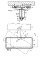
- Figure 1 is a side elevational view illustrating the auxiliary work surface assembly of this invention as mounted on a conventional primary work surface.
- Figure 2 is a sectional view similar to Figure 1 but showing the auxiliary work surface assembly on an enlarged scale.
- Figure 3 is a fragmentary top view of the carriage assembly as taken along line III-III in Figure 2.
- Figure 4 is an end elevational view taken along line IV-IV in Figure 1.
- Figures 5, 6 and 7 are enlarged, fragmentary sectional views taken respectively along lines V-V, VI-VI and VII-VII in Figure 2.
- Figure 8 is a fragmentary top view showing different locations of the auxiliary work surface relative to the primary work surface.
- Figure 9 is a fragmentary elevational view of a modification.
- Figure 10 is an end view along line X-X in Figure 9.
- Figures 1 and 2 illustrate an adjustable
work surface assembly 10 according to the invention. This assembly includes a shelflikeauxiliary support 11 which is sized to enable it to comfortably support thereon a keyboard K as conventionally associated with a computer. Thiskeyboard support 11 is interconnected by asupport mechanism 12 to a conventional stationary work-surface support 13, the latter conventionally comprising the top of a table, desk or other similar work surface structure. - The
work surface assembly 10 and thesupport mechanism 12 which interconnects thekeyboard support 11 to thestationary support 13, provides theauxiliary support 11 with a wide range of movements relative to theprimary support 13 so that the keyboard K can be positioned for optimum user comfort while also providing maximum flexibility in terms of positional movement. Thissupport mechanism 12 enables thekeyboard support 11 to be horizontally moved between an outer position wherein it is spaced a substantial distance forwardly from thefront edge 14 of thestationary support 13, as illustrated in Figure 1, and an inner position wherein thiskeyboard support 11 is disposed closely adjacent thefront edge 14 of thestationary support 13, as illustrated by solid lines in Figure 2. Thissupport mechanism 12 also enables thekeyboard support 11 to be vertically displaced through a selected distance, such as between an upper position wherein thekeyboard support 11 is approximately planar with thestationary support 13 as indicated by the solid line positions in Figures 1 and 2, and a lowered position wherein thekeyboard support 11 is positioned vertically downwardly a substantial distance below thestationary support 13, as indicated by dotted lines in Figure 2. Thissupport mechanism 12 enables the keyboard support to be positioned horizontally at any location between these inner and outer positions, and also vertically at any location between these upper and lower positions.Support mechanism 12 also enables thekeyboard support 11 and the keyboard K mounted thereon, when thekeyboard support 11 is in its lowermost position as indicated by dotted lines in Figure 2, to be moved rearwardly into a storage position located totally below thestationary support 13 as indicated by dotted lines in Figure 1. Thesupport mechanism 12 also includes hinge structures which enable thekeyboard support 11 to be angularly tilted or displaced horizontally sidewardly relative to thework surface 13, substantially as indicated by dotted lines in Figure 8. - To provide the numerous movements and positional relationships described above, the
support mechanism 12 includes acarriage 16 slidably supported on the underside of thestationary support 13, which carriage mounts thereon a firstvertical hinge assembly 17. Thishinge assembly 17 is connected to the rearward end of a link means 18, the latter being a vertical parallelogram linkage in the preferred embodiment, which at its forward end is connected to a secondvertical hinge assembly 19 as mounted on the underside of thekeyboard support 11. - To movably and guidably support the
carriage 16, the underside ofstationary support 13 has guide rail means 21 fixed thereto. This guide rail means includes a base plate 22 (Figure 6) secured to the underside of thesupport 13, and a pair ofparallel guide rails 23 are fixed thereto and project rearwardly from a location adjacent thefront edge 14 of thesupport 13 to a location adjacent the rear edge thereof. Theserails 23, in cooperation withbase plate 22, define a pair of opposed, sidewardly openingguide channels 24. The forward ends of these guide channels are closed by astop plate 29 which extends thereacross in close proximity to thefront edge 14. - The
carriage 16 includes a shallow, upwardly opening channel or U-shapedmember 26. Thelegs 27 ofmember 26 project upwardly adjacent thechannels 24, and theselegs 27 mount pairs of front andrear rollers 28 which are confined within thechannels 24. - The structure of hinge means 17 will now be des=ribed. A U-shaped, rearwardly opening
bracket 31 projects downwardly from thecarriage plate 26 and is fixed thereto. Thisbracket 31 mounts thereon an L-shaped hinge bracket 32, the latter defining alower hinge plate 33 which is parallel with and spaced downwardly from theplanar center portion 26A of thecarriage member 26. A verticallyelongated hinge shaft 36 extends between theseplates hinge shaft 34 is threaded into anut 35 which is fixed to thecarriage plate 26. Thishinge shaft 34, which defines a firstvertical hinge axis 36, has an enlarged head 37 on the lower end thereof, and a plurality ofspring washers 38 surround the shaft and are supported on the head 37. Thesespring washers 38 react against anannular bushing 39, the latter being slidably supported on theshaft 34 and slidably supported within an enlarged opening formed in thehinge plate 33, whereby thebushing 39 is resiliently urged upwardly into engagement with anintermediate member 41 which is pivotally supported on thehinge shaft 34. - This pivotally supported
intermediate member 41 includes parallel top and bottom walls 42 (Figure 5) rigidly joined together bysidewalls 43. The resiliently urged bushing 39 bears against thebottom wall 42 so that thetop wall 42 is hence maintained in engagement with aplastic support washer 44 which functions as part of a friction brake to normally prevent the horizontal pivoting of theintermediate member 41 within the stationary bracket structure about thevertical hinge axis 36. - Considering now the
keyboard support 11, same is preferably formed of a plastics material which is suitably molded about acentral core 45, whereby the keyboard support defines an upperplanar surface 46 which is substantially horizontal and approximately parallel with theupper surface 47 of thestationary support 13. Thekeyboard support 11 preferably has a small upwardly projectingridge 48 around the periphery thereof.Support 11 also has asupport plate 50 fixedly molded in the underside thereof, whichsupport plate 50 has avertical bracket plate 49 fixed thereto and projecting downwardly therefrom. Thisbracket 49 fixedly mounts thereon an L-shaped bracket 51 having alower hinge plate 52 which is parallel with and spaced downwardly from thesupport plate 50. A hinge pin or shaft 54 extends vertically between theplates vertical hinge axis 56. The upper end of this hinge pin 54 is threadably anchored within anut 53 which is fixed to thesupport plate 50, whereas the lower end of the hinge pin has an enlarged head 55 andspring washers 57 are mounted thereon and resiliently coact with anannular bushing 58 which is slidably supported on the hinge pin 54 and extends through an opening in thehinge plate 52 for engagement with the lower wall of anintermediate member 59 which is urged upwardly so that its upper wall engages thefriction washer 60. Themember 59 is substantially identical to the aforedescribedintermediate member 41 and is supported for pivoting movement on the hinge pin 54 about thevertical hinge axis 56 thereof. This latter-described structure hence defines the secondvertical hinge assembly 19. - Considering now the link means 18, same includes elongated upper and
lower links upper link 61 is, in the illustrated embodiment, of a downwardly opening U-shaped configuration and includes a pair of parallelvertical side legs 63 joined together by atop wall 64. The rearward end of thisupper link 61 is hingedly joined to theintermediate member 41 by ahorizontal hinge pin 65 which extends through the intermediate member sidewalls 43 and is supported on the link sidewalls 63, which latter sidewalls overlap the outer surfaces of the intermediate member sidewalls 43. A similarhorizontal hinge pin 66 pivotally joins the forward end oflink 61 to the otherintermediate member 59. - The
lower link 62, in the preferred embodiment, is of a tubular cross section and is sized so as to be totally confined between thesidewalls 63 of the upper link inasmuch as this provides the overall link means with a more streamlined appearance. The rearward end of thislower link 62 is also hingedly joined to theintermediate member 41 by ahorizontal hinge pin 68 which extends through the lower link so that the opposite ends there of are appropriately supported on the intermediate member sidewalls 43. A similarhorizontal hinge pin 69 joins the forward end of thelink 62 to the otherintermediate member 59. Thelinks links intermediate members keyboard support 11, while at the same time maintaining theupper surface 46 of the keyboard support 1- substantially horizontal irrespective of the elevation thereof. - To enable
keyboard support 11 to be stationarily supported at any selected elevational position, a lock means 71 is provided at the outer end of the link means 18 so as to be readily accessible to the keyboard operator. This lock means 71 includes the lowerouter hinge pin 69, whichpin 69 is of increased length so as to project throughelongated slots 72 formed in thesidewalls 63 of theupper link 61, whichslots 72 are generated about the axis of the upperouter hinge pin 66 as a center. Thehinge pin 69 projects through thesearcuate slots 72 and has anenlarged head 73 at one end thereof, and a threadedend 74 at the other end thereof. Ahand knob 76 is positioned adjacent thesidewall 63 and is threadably engaged withend 74 ofhinge pin 69, whichhand knob 76 has the hub thereof adapted to engage afriction washer 77 which surrounds the hinge pin and is clampable between the hub of theknob 76 and thesidewall 63. - When the parallelogram linkage 61-62 is vertically pivoted upwardly or downwardly, the
hinge pin 69 is slidably moved along thearcuate slots 72. The forward end of the slot acts as a stop and defines the lowermost elevational position of the keyboard support, whereas the rearward end of theslot 72 acts as a stop for defining the uppermost elevational position of the keyboard support. Whenhand knob 76 is manually rotated to snugly frictionally engage thefriction washer 77 between the hand knob and thesidewall 63, this prevents thehinge pin 69 from being slidably displaced within theslot 72, thereby holding theparallel links keyboard support 11 is stationarily held in the selected elevational position. - Link means 18 also has spring means associated therewith for urging the
keyboard support 11 into its uppermost elevational position. This spring means includes a pair of elongated tension springs 79 which are confined within the interior of theupper link 61, whereby one end of thesprings 79 are anchored around the rearupper hinge pin 65, whereas the other ends of thesesprings 79 are anchored to thelower link 62, such as in the vicinity of thefront hinge pin 69.Springs 79 continually bias the linkage 61-62 in a counterclockwise direction toward the uppermost elevational position. - To define the inner and outer positional limits of the
keyboard support 11 when the latter is in its use position, and to prevent the keyboard support from being moved into its storage position except when the keyboard support is in its lowermost elevational position, theassembly 10 also includes apositional limit structure 81 coacting between thestationary support 13 and thesupport mechanism 12. Thislimit structure 81 includes anelongated control rail 82 fixed to the underside of thesupport surface 13 at a location between the guide rails 23. Thiscontrol rail 82 projects forwardly from the rearward end of the guide rails and terminates at its forward end in atransverse stop surface 83. Thisstop surface 83 is spaced rearwardly a substantial distance from thefront edge 14, and in fact is spaced rearwardly a substantial distance from thefront stop 29. The spacing between thesestops keyboard support 11 relative to thestationary support 13. - This
limit structure 81 also includes a cooperating stop element associated with thesupport mechanism 12. This is provided by abracket 86 which is secured to and projects upwardly from theupper link 61 adjacent the rearward end thereof, whichbracket 86 supports thereon a cam or stop in the form of aroller 87. Thisroller 87 is movable horizontally between and is adapted to abuttingly contact the opposed stop surfaces 83 and 29 for limiting the respective inner and outer positions of thekeyboard support 11 so long as the latter is spaced slightly upwardly above its lowermost elevational position. Further, so long as thekeyboard support 11 is spaced slightly upwardly above its lowermost elevational position, theroller 87 will abut therear stop surface 83 and prevent thekeyboard support 11 from being moved significantly under thestationary support 13. This thus prevents the keyboard support from being pushed inwardly a sufficient extent as to cause the keyboard K to strike thefront edge 14. - However, when the
keyboard support 11 is in its lowermost elevational position, then theroller 87 is disposed at an elevation whereby it will move rearwardly past therear stop surface 83, and in fact thisroller 87 will effectively rollingly move along thelower control surface 84 defined on thecontrol rail 82, whereupon thekeyboard support 11 and the keyboard K thereon can hence be moved rearwardly into a storage position located in its entirety below thestationary support 13. When in this lowermost elevational position, sufficient clearance exists for the keyboard K to be stored totally beneath thestationary support 13. Further, the engagement of theroller 87 with thecontrol surface 84 maintains the keyboard support in this lowermost elevational position so as to permit safe storage of the keyboard K beneath thestationary support 13. - To restrict accidental displacement of the
carriage 16 along the guide rails 23, the carriage additionally mounts thereon a friction brake which cooperates with thestationary base plate 22. This friction brake includes a friction brake block 88 (of plastics material) mounted on thecarriage plate 26 and disposed in frictional sliding engagement with the guide rails 23 so as to permit linear displacement of the carriage only when the operator applies a substantial force to theassembly 10 so as to forcibly move the carriage and hence thekeyboard support 11 inwardly or outwardly relative to thestationary support 13. This friction brake is otherwise sufficient to stationarily hold the carriage in the selected position. The brake blocks 88 are mounted on thecarriage legs 27 bypins 89, and springs 90 urge the brake blocks against the guide rails. - With the illustrated embodiment, the
keyboard support 11 mounting thereon the keyboard K will normally be stored in the storage position indicated by dotted lines in Figure 1, in which position thekeyboard support 11 is in its lowermost elevational position and is retracted rearwardly so as to be disposed entirely below thework surface 13. In this storage position, theroller 87 engages thecontrol rail 82 and positively maintains thesupport 11 in this lowermost position, in opposition to the urging ofsprings 79. - To use the keyboard, the operator will grasp the edge of
support 11 andslide assembly 10 outwardly into a use position wherein thesupport 11 is positioned in front of thestationary support 13. As theassembly 10 is manually moved outwardly, thesupport 11 is maintained in its lowermost position until reaching a position wherein the rear edge ofsupport 11 is approximately vertically aligned with thefront edge 14 ofsupport 13. At that point, theroller 87 disengages the forward end ofcontrol rail 82 and springs 79 then resiliently urge the linkage 61-62 counterclockwise, wherebysupport 11 is swung upwardly into its uppermost position wherein the rear edge ofsupport 11 is closely adjacent but spaced slightly from thefront edge 14 ofsupport 13. This uppermost use position is limited by the engagement ofhinge pin 69 with the outer end of thearcuate slots 72. In this uppermost use position, theroller 87 is disposed substantially in engagement with thebase plate 22. The operator can then horizontally position thekeyboard support 11 relative to thestationary support 13 by pulling thesupport 11 further outwardly to increase the spacing thereof from thestationary support 13, which outward pulling is accompanied by corresponding displacement of thecarriage 16. Thefriction brake 88 then holds thecarriage 16 stationary in the selected position. If desired, the operator can press downwardly on thesupport 11, thereby causing the linkage 61-62 to swing downwardly about the hinge pins 65-66 in opposition to the urging of thesprings 79, which will cause a lowering of thesupport 11 while still maintaining the upper surface horizontal. Thesupport 11 can thus he positioned elevationally either at or anywhere between the upper and lower elevational positions indicated in Figure 2. When thesupport 11 is at the des--red elevation, the operator then manually grips thehand knob 76 and rotatably tightens same so that thefriction lock 71 will be engaged, thereby preventing displacement of thehinge pin 69 along theslots 72, and hence rigidly connecting thelinks keyboard support 11 at the selected elevation. - The
keyboard support 11 can also be angularly displaced relative to thestationary support 13. This angular movement can occur about either of the hinge axes 36 and 56. For example, thewasher 60 functions as a friction brake (due to urging of spring washers 57) which coacts between thesupport 11 andintermediate member 59 for normally holding thesupport 11 stationary relative to theouter hinge axis 56. However, by exerting sufficient manual torque on thesupport 11, this friction brake can be overcome so that thesupport 11 can be manually pivoted about the outervertical hinge axis 56 to permit angular orientation of the support about this latter axis, substantially as indicated by dash-dot lines in Figure 8. Alternately, the desired angularity of thesupport 11 can be achieved solely by hingeably swinging the assembly about the innervertical hinge axis 36. Again, thewasher 44 creates a friction brake (due to urging of springs 38) which coacts between thecarriage 26 and theintermediate member 41 for normally preventing pivoting movement about thisaxis 36, but the operator can again manually overcome this friction brake and angularly displace both thesupport 11 and thelinkage 18 about this innervertical axis 36. - The operator can also pivot the link means 18 in one rotational direction about the
inner hinge axis 36, and pivot thesupport 11 in the opposite rotational direction about the outervertical hinge axis 56, move thesupport 11 sidewardly while still maintaining thesupport 11 substantially parallel with thefront edge 14, this latter position being indicated by dotted lines in Figure 8. - With the
keyboard support 11 in its use position and at any elevation other than its lowermost position, any accidental inward movement of thekeyboard support 11 toward thestationary support 13, such as due to someone inadvertently leaning against the front edge thereof, will be limited to movement into a position wherein the rear edge of thesupport 11 is adjacent or approximately vertically aligned with thefront edge 14 inasmuch as theroller 87 will engage theperpendicular stop surface 83 and prevent any further inward movement. This hence prevents the keyboard K from striking theedge 14. The assembly can be moved into its storage position only by the operator first manually rotating thehand knob 76 so as to release thefriction lock 71, following which the operator must then manually depress thesupport 11 into its lowermost use position as limited by thehinge pin 69 sliding along theslots 72 until the hinge pin contacts the rear ends of these slots, in which position thecontrol roller 87 has been lowered below thestop surface 83 so as to permit thecarriage 16 to then be rollingly moved rearwardly from thestop surface 83 into the rear storage position. - It is anticipated that the
support 11 when in its use position will have a permissible range of both elevational and horizontal displacement in the order of six to seven inches. However, this range of movement can obviously be increased or decreased depending on desired use conditions. - The assembly of this invention can be easily manually manipulated to enable it to accommodate many different use positions and orientations, while at =he same time the operator has to control only a single brake, namely by use of the readily
accessible hand knob 76. - Figures 9 and 10 illustrate a variation of the hinge means used for connecting the inner end of the link means 18 to the
carriage 16. In this variation, the parts are designated by the same reference numerals utilized in Figures 1-7 except for the addition of a prime (') thereto. - The modified inner hinge assembly 17' shown in Figures 9 and 10 increases the permissible angular displacement of the work surface assembly about the vertical axis 36', and in fact permits the work surface assembly to be rotated through 360° about the hinge axis 36'. The inner hinge pin 34' is again fixed to and projects vertically downwardly from the center portion of the carriage plate 26'. The intermediate member 41' is rotatably supported on the hinge pin 34' and includes a
top swivel plate 91 which is positioned directly below the underside of the carriage plate 26', with asuitable friction pad 92 being provided on theplate 91 for frictional engagement with the carriage plate 26'. Intermediate member 41' also includes a downwardly opening,U-shaped part 93 which has theupper wall 94 thereof abutted against theswivel plate 91 and rotatably surrounding the hinge pin 34'. Theswivel plate 91 has appropriate reinforcingbrackets 96 which are fixedly engaged to the opposite legs orsidewalls 97 of thepart 93. Theselatter sidewalls 97 function the same as theside legs 43 of theintermediate member 41 described above, and hence hingedly connect to the inner ends of thelinks - With the arrangement of Figures 9 and 10, the work surface assembly hence can be rotatably swivelled about the inner vertical hinge axis 36' through 360° if necessary. Thus, if the assembly is mounted on a narrow table, the assembly can be swung about the axis 36' so as to position the
support 11 adjacent either side of the table at intervals spaced 180° apart, or adjacent an end edge of the table. Thesupport 11 is preferably provided with a stop fixed to and projecting upwardly therefrom adjacent the rearward edge thereof, which stop contacts theedge 14 and prevents thesupport 11 from being moved into a position below thestationary support 13. This stop has a height which permits it to pass under thesupport 13 only when thesupport 11 is in its lowermost elevational position so as to insure proper clearance for the keyboard. - As a further modification, the guide rail means 21 can be mounted on the underside of the
stationary support 11 so as to extend parallel with the free edge 14 (rather than perpendicular thereto as illustrated by Figures 1 and 2). With the guide rail means 21 extending parallel to thesupport edge 14, and with the link means 18 extending perpendicular to the direction of movement along the rail means, then the assembly can be moved laterally along the edge of the work surface so that the keyboard can be moved from one work station to another.
Claims (10)
Applications Claiming Priority (2)
| Application Number | Priority Date | Filing Date | Title |
|---|---|---|---|
| US38613182A | 1982-06-07 | 1982-06-07 | |
| US386131 | 1982-06-07 |
Publications (2)
| Publication Number | Publication Date |
|---|---|
| EP0096373A1 true EP0096373A1 (en) | 1983-12-21 |
| EP0096373B1 EP0096373B1 (en) | 1989-04-26 |
Family
ID=23524297
Family Applications (1)
| Application Number | Title | Priority Date | Filing Date |
|---|---|---|---|
| EP83105470A Expired EP0096373B1 (en) | 1982-06-07 | 1983-06-01 | Adjustable support for crt keyboard |
Country Status (3)
| Country | Link |
|---|---|
| EP (1) | EP0096373B1 (en) |
| JP (1) | JPS592126A (en) |
| DE (1) | DE3379750D1 (en) |
Cited By (14)
| Publication number | Priority date | Publication date | Assignee | Title |
|---|---|---|---|---|
| FR2554269A1 (en) * | 1983-10-26 | 1985-05-03 | Saunier Duval | Variable geometry control and drive console |
| WO1985002524A1 (en) * | 1983-12-09 | 1985-06-20 | Data Decor Pty. Ltd. | Height adjustable support arm |
| US4638969A (en) * | 1984-12-24 | 1987-01-27 | Milliken Research Corporation | Video display arrangement |
| EP0281093A2 (en) * | 1987-03-03 | 1988-09-07 | Hans Dieter Horn | Support for an apparatus |
| DE8813958U1 (en) * | 1988-11-08 | 1989-01-12 | Steelform Ab, Lammhult, Se | |
| WO1991020023A2 (en) * | 1990-06-13 | 1991-12-26 | Waterloo Furniture Components Ltd. | Improved adjustable support mechanism for a keyboard platform |
| EP0707809A3 (en) * | 1994-10-20 | 2000-10-18 | SCHÜCO International KG | Work table |
| EP1191866A1 (en) * | 1999-06-07 | 2002-04-03 | ACCURIDE INTERNATIONAL, Inc. | Extendable swivel mounting bracket |
| US7841570B2 (en) | 1997-03-12 | 2010-11-30 | Humanscale Corporation | Keyboard support mechanism |
| CN111971503A (en) * | 2018-04-13 | 2020-11-20 | 微软技术许可有限责任公司 | System and method for providing multiple location display |
| CN112824633A (en) * | 2019-11-21 | 2021-05-21 | 云丁网络技术(北京)有限公司 | Intelligent lock |
| US11493953B2 (en) | 2019-07-01 | 2022-11-08 | Microsoft Technology Licensing, Llc | Multi-position display with an unfixed center of rotation |
| US11538442B2 (en) | 2018-04-13 | 2022-12-27 | Microsoft Technology Licensing, Llc | Systems and methods of displaying virtual elements on a multipositional display |
| US11572975B2 (en) | 2018-04-13 | 2023-02-07 | Microsoft Technology Licensing, Llc | Systems and methods of providing a multipositional display |
Families Citing this family (1)
| Publication number | Priority date | Publication date | Assignee | Title |
|---|---|---|---|---|
| US5257767A (en) | 1990-06-13 | 1993-11-02 | Waterloo Furniture Components, Ltd. | Adjustable support mechanism for a keyboard platform |
Citations (6)
| Publication number | Priority date | Publication date | Assignee | Title |
|---|---|---|---|---|
| US3516343A (en) * | 1967-07-26 | 1970-06-23 | Gilbert H Tunney | Camera-positioning apparatus |
| US3891301A (en) * | 1972-08-18 | 1975-06-24 | Contraves Ag | Adjustable support or stand for an optical observation instrument |
| EP0010491A1 (en) * | 1978-10-12 | 1980-04-30 | Compagnie du RONEO société anonyme | Support for a computer terminal |
| DE2847135A1 (en) * | 1978-10-30 | 1980-05-08 | Nixdorf Computer Ag | Support mechanism for VDU - has arm on base section rotating around horizontal axis and top link around parallel axis allowing adjustment to suit operator |
| EP0038068A1 (en) * | 1980-04-15 | 1981-10-21 | Siemens Aktiengesellschaft | Device for fastening a monitor to a text processing station |
| EP0046225A2 (en) * | 1980-08-20 | 1982-02-24 | Siemens Aktiengesellschaft | Device for mounting a display unit on a working area |
Family Cites Families (1)
| Publication number | Priority date | Publication date | Assignee | Title |
|---|---|---|---|---|
| US2541075A (en) * | 1947-07-10 | 1951-02-13 | Clarence W Koch | Typewriter desk |
-
1983
- 1983-06-01 DE DE8383105470T patent/DE3379750D1/en not_active Expired
- 1983-06-01 EP EP83105470A patent/EP0096373B1/en not_active Expired
- 1983-06-07 JP JP58101572A patent/JPS592126A/en active Granted
Patent Citations (6)
| Publication number | Priority date | Publication date | Assignee | Title |
|---|---|---|---|---|
| US3516343A (en) * | 1967-07-26 | 1970-06-23 | Gilbert H Tunney | Camera-positioning apparatus |
| US3891301A (en) * | 1972-08-18 | 1975-06-24 | Contraves Ag | Adjustable support or stand for an optical observation instrument |
| EP0010491A1 (en) * | 1978-10-12 | 1980-04-30 | Compagnie du RONEO société anonyme | Support for a computer terminal |
| DE2847135A1 (en) * | 1978-10-30 | 1980-05-08 | Nixdorf Computer Ag | Support mechanism for VDU - has arm on base section rotating around horizontal axis and top link around parallel axis allowing adjustment to suit operator |
| EP0038068A1 (en) * | 1980-04-15 | 1981-10-21 | Siemens Aktiengesellschaft | Device for fastening a monitor to a text processing station |
| EP0046225A2 (en) * | 1980-08-20 | 1982-02-24 | Siemens Aktiengesellschaft | Device for mounting a display unit on a working area |
Cited By (18)
| Publication number | Priority date | Publication date | Assignee | Title |
|---|---|---|---|---|
| FR2554269A1 (en) * | 1983-10-26 | 1985-05-03 | Saunier Duval | Variable geometry control and drive console |
| WO1985002524A1 (en) * | 1983-12-09 | 1985-06-20 | Data Decor Pty. Ltd. | Height adjustable support arm |
| US4638969A (en) * | 1984-12-24 | 1987-01-27 | Milliken Research Corporation | Video display arrangement |
| EP0281093A2 (en) * | 1987-03-03 | 1988-09-07 | Hans Dieter Horn | Support for an apparatus |
| EP0281093A3 (en) * | 1987-03-03 | 1989-06-14 | Hans Dieter Horn | Support for an apparatus |
| DE8813958U1 (en) * | 1988-11-08 | 1989-01-12 | Steelform Ab, Lammhult, Se | |
| WO1991020023A2 (en) * | 1990-06-13 | 1991-12-26 | Waterloo Furniture Components Ltd. | Improved adjustable support mechanism for a keyboard platform |
| WO1991020023A3 (en) * | 1990-06-13 | 1992-01-23 | Waterloo Furniture Components | Improved adjustable support mechanism for a keyboard platform |
| EP0707809A3 (en) * | 1994-10-20 | 2000-10-18 | SCHÜCO International KG | Work table |
| US7841570B2 (en) | 1997-03-12 | 2010-11-30 | Humanscale Corporation | Keyboard support mechanism |
| US7841569B2 (en) | 1997-03-12 | 2010-11-30 | Humanscale Corporation | Keyboard support mechanism |
| EP1191866A1 (en) * | 1999-06-07 | 2002-04-03 | ACCURIDE INTERNATIONAL, Inc. | Extendable swivel mounting bracket |
| EP1191866A4 (en) * | 1999-06-07 | 2002-08-14 | Accuride Int Inc | Extendable swivel mounting bracket |
| CN111971503A (en) * | 2018-04-13 | 2020-11-20 | 微软技术许可有限责任公司 | System and method for providing multiple location display |
| US11538442B2 (en) | 2018-04-13 | 2022-12-27 | Microsoft Technology Licensing, Llc | Systems and methods of displaying virtual elements on a multipositional display |
| US11572975B2 (en) | 2018-04-13 | 2023-02-07 | Microsoft Technology Licensing, Llc | Systems and methods of providing a multipositional display |
| US11493953B2 (en) | 2019-07-01 | 2022-11-08 | Microsoft Technology Licensing, Llc | Multi-position display with an unfixed center of rotation |
| CN112824633A (en) * | 2019-11-21 | 2021-05-21 | 云丁网络技术(北京)有限公司 | Intelligent lock |
Also Published As
| Publication number | Publication date |
|---|---|
| JPS592126A (en) | 1984-01-07 |
| EP0096373B1 (en) | 1989-04-26 |
| JPH046976B2 (en) | 1992-02-07 |
| DE3379750D1 (en) | 1989-06-01 |
Similar Documents
| Publication | Publication Date | Title |
|---|---|---|
| US4616798A (en) | Adjustable support for CRT keyboard | |
| US4644875A (en) | Adjustable keyboard supporting mechanism | |
| US6273382B1 (en) | Adjustable tilt-down keyboard support device | |
| EP0096373A1 (en) | Adjustable support for CRT keyboard | |
| US6076785A (en) | Ergonomic sit/stand keyboard support mechanism | |
| US4706919A (en) | Keyboard support with automatic lowering mechanism | |
| US5257767A (en) | Adjustable support mechanism for a keyboard platform | |
| US5145136A (en) | Adjustable support mechanism for a keyboard platform | |
| US5037054A (en) | Adjustable support mechanism for a keyboard platform | |
| US6270047B1 (en) | Keyboard tilt mechanism | |
| US5836560A (en) | Articulated keyboard shelf | |
| US8567735B2 (en) | Work station with height adjustment lock | |
| US5294087A (en) | Adjustable keyboard holder for computer workstation | |
| US20040099779A1 (en) | Keyboard support mechanism | |
| US5098053A (en) | Selectively controlled keyboard support | |
| US5483898A (en) | Tilting and sliding surface assembly for a table | |
| US4687166A (en) | Swivel arm | |
| US6135404A (en) | Keyboard mounting mechanism | |
| US5108354A (en) | Barbell support | |
| US5368377A (en) | Flip-top computer workstation | |
| CA1179932A (en) | Backgauge structure | |
| KR20060097732A (en) | Adjustable keyboard support assembly | |
| US6257531B1 (en) | Ergonomic workstation and keyboard support | |
| US5074221A (en) | Lift mechanism for tiltable worksurface | |
| US3468589A (en) | Level adjusting mechanism for free arm sewing machine |
Legal Events
| Date | Code | Title | Description |
|---|---|---|---|
| PUAI | Public reference made under article 153(3) epc to a published international application that has entered the european phase |
Free format text: ORIGINAL CODE: 0009012 |
|
| AK | Designated contracting states |
Designated state(s): BE DE FR GB SE |
|
| 17P | Request for examination filed |
Effective date: 19840615 |
|
| GRAA | (expected) grant |
Free format text: ORIGINAL CODE: 0009210 |
|
| AK | Designated contracting states |
Kind code of ref document: B1 Designated state(s): BE DE FR GB SE |
|
| PG25 | Lapsed in a contracting state [announced via postgrant information from national office to epo] |
Ref country code: SE Effective date: 19890426 |
|
| REF | Corresponds to: |
Ref document number: 3379750 Country of ref document: DE Date of ref document: 19890601 |
|
| ET | Fr: translation filed | ||
| PLBE | No opposition filed within time limit |
Free format text: ORIGINAL CODE: 0009261 |
|
| STAA | Information on the status of an ep patent application or granted ep patent |
Free format text: STATUS: NO OPPOSITION FILED WITHIN TIME LIMIT |
|
| 26N | No opposition filed | ||
| PGFP | Annual fee paid to national office [announced via postgrant information from national office to epo] |
Ref country code: GB Payment date: 19900524 Year of fee payment: 8 |
|
| PGFP | Annual fee paid to national office [announced via postgrant information from national office to epo] |
Ref country code: FR Payment date: 19900606 Year of fee payment: 8 |
|
| PGFP | Annual fee paid to national office [announced via postgrant information from national office to epo] |
Ref country code: BE Payment date: 19900612 Year of fee payment: 8 |
|
| PGFP | Annual fee paid to national office [announced via postgrant information from national office to epo] |
Ref country code: DE Payment date: 19900730 Year of fee payment: 8 |
|
| PG25 | Lapsed in a contracting state [announced via postgrant information from national office to epo] |
Ref country code: GB Effective date: 19910601 |
|
| PG25 | Lapsed in a contracting state [announced via postgrant information from national office to epo] |
Ref country code: BE Effective date: 19910630 |
|
| BERE | Be: lapsed |
Owner name: HAWORTH INC. Effective date: 19910630 |
|
| GBPC | Gb: european patent ceased through non-payment of renewal fee | ||
| PG25 | Lapsed in a contracting state [announced via postgrant information from national office to epo] |
Ref country code: FR Effective date: 19920228 |
|
| PG25 | Lapsed in a contracting state [announced via postgrant information from national office to epo] |
Ref country code: DE Effective date: 19920401 |