EP0087249A2 - Apparatus for reproducing video and audio signals - Google Patents
Apparatus for reproducing video and audio signals Download PDFInfo
- Publication number
- EP0087249A2 EP0087249A2 EP83300703A EP83300703A EP0087249A2 EP 0087249 A2 EP0087249 A2 EP 0087249A2 EP 83300703 A EP83300703 A EP 83300703A EP 83300703 A EP83300703 A EP 83300703A EP 0087249 A2 EP0087249 A2 EP 0087249A2
- Authority
- EP
- European Patent Office
- Prior art keywords
- drop
- frequency
- signal
- signals
- mixed
- Prior art date
- Legal status (The legal status is an assumption and is not a legal conclusion. Google has not performed a legal analysis and makes no representation as to the accuracy of the status listed.)
- Granted
Links
Images


Classifications
-
- H—ELECTRICITY
- H04—ELECTRIC COMMUNICATION TECHNIQUE
- H04N—PICTORIAL COMMUNICATION, e.g. TELEVISION
- H04N9/00—Details of colour television systems
- H04N9/79—Processing of colour television signals in connection with recording
- H04N9/80—Transformation of the television signal for recording, e.g. modulation, frequency changing; Inverse transformation for playback
- H04N9/82—Transformation of the television signal for recording, e.g. modulation, frequency changing; Inverse transformation for playback the individual colour picture signal components being recorded simultaneously only
- H04N9/83—Transformation of the television signal for recording, e.g. modulation, frequency changing; Inverse transformation for playback the individual colour picture signal components being recorded simultaneously only the recorded chrominance signal occupying a frequency band under the frequency band of the recorded brightness signal
- H04N9/835—Transformation of the television signal for recording, e.g. modulation, frequency changing; Inverse transformation for playback the individual colour picture signal components being recorded simultaneously only the recorded chrominance signal occupying a frequency band under the frequency band of the recorded brightness signal involving processing of the sound signal
- H04N9/8355—Transformation of the television signal for recording, e.g. modulation, frequency changing; Inverse transformation for playback the individual colour picture signal components being recorded simultaneously only the recorded chrominance signal occupying a frequency band under the frequency band of the recorded brightness signal involving processing of the sound signal the sound carriers being frequency multiplexed between the luminance carrier and the chrominance carrier
-
- H—ELECTRICITY
- H04—ELECTRIC COMMUNICATION TECHNIQUE
- H04N—PICTORIAL COMMUNICATION, e.g. TELEVISION
- H04N9/00—Details of colour television systems
- H04N9/79—Processing of colour television signals in connection with recording
- H04N9/87—Regeneration of colour television signals
- H04N9/88—Signal drop-out compensation
Landscapes
- Engineering & Computer Science (AREA)
- Multimedia (AREA)
- Signal Processing (AREA)
- Television Signal Processing For Recording (AREA)
- Signal Processing Not Specific To The Method Of Recording And Reproducing (AREA)
Abstract
Description
- This invention relates to apparatus for reproducing video and audio signals, such as may constitute a television signal, that have been recorded on a magnetic medium.
- In video tape recorders, when recording a colour television signal on a magnetic tape, the chrominance and luminance signal components that constitute the colour video signal are usually separated, and the carrier frequency of the chrominance signal component is converted to a low value relative to the higher carrier frequency that the luminance component frequency modulates. The frequency-converted chrominance signal component and the high side band of the frequency-modulated luminance signal component are then mixed or combined to form a composite colour video signal that is recorded on a magnetic tape in successive, parallel record tracks extending obliquely with respect to the longitudinal or running direction of the tape. In such a system for recording a colour television signal, the audio signal is recorded on the tape in separate record tracks that extend in the longitudinal direction of the tape.
- In such,a recording system, the oblique tracks in which the composite colour video signal made up of the frequency-converted chrominance signal component and the frequency-modulated luminance signal component are recorded, are formed by first and second substantially diametrically opposed rotary magnetic heads both supplied with the composite colour video signal. The heads alternately scan the tape along a path at an angle to the longitudinal direction in which the tape is transported. In order to increase the recording density of the colour video signal on the tape, and thereby increase the duration of the recording, it has been known to restrict the speed at which the tape is transported so that the successive oblique tracks scanned by the heads will be more closely spaced or be immediately adjacent to each other, that is, so that the spaces or so-called guard bands between the adjacent tracks will be eliminated. Nevertheless, in such a case, the problem of "cross-talk" arises in the reproduction mode. In other words, during reproduction of these closely arranged tracks, a transducer or head scanning one of the oblique tracks for reproducing the composite colour video signal recorded therein will also reproduce signals from the next adjacent tracks, such signals being known as cross-talk.
- This problem of cross-talk has been substantially solved, at least in respect of the relatively high frequency frequency-modulated luminance signal component of the recorded composite colour video signal, by providing the first and second rotary magnetic heads with different azimuth angles, so that the composite colour video signal will be recorded in each oblique track by a head having an azimuth angle different from the azimuth angle of the head with which the composite colour video signal is recorded in the next adjacent track. Subsequently, during reproduction, each oblique track is scanned by the rotary magnetic head having the corresponding azimuth angle, with the result that a substantial and beneficial azimuth loss is experienced in the relatively high frequency components of the cross-talk derived from the adjacent tracks. Thus, the cross-talk in the frequency-modulated luminance signal component is substantially suppressed.
- Nevertheless, the azimuth loss effect is more serious with respect to the low frequency band of the cross-talk, that is, with respect to the frequency-converted chrominance signal component, so that other measures need be taken to reduce or eliminate the low-frequency component of the cross-talk. As disclosed in detail in our U.S. Patent No. 4,007,482, cross-talk in the frequency-converted chrominance signal situated in a relatively low-frequency band is substantially eliminated by recording the chrominance signal component with different first and second carriers in the adjacent tracks, respectively. These first and second carriers, which have been modulated by the chrominance signal component and recorded in adjacent tracks, may be distinguished from each other by their respective frequency and/or polarity characteristics so that, upon reproduction of the signal recorded in a particular track, the low frequency component of the cross-talk from the tracks next to it can be suppressed or eliminated by reason of the different frequency, and/or polarity, or phase characteristics of the respective carriers.
- More specifically, as disclosed in the above U.S. patent, the chrominance signal component of the colour video signal to be recorded may be frequency-converted so as selectively to produce first and second frequency converted signals which, when considered instantaneously, have the same carrier frequency but which differ from each other in their phase or polarity characteristics. In this case, each of the line areas of one track may have recorded therein a frequency-converted chrominance signal component with a carrier of constant polarity, while in the next adjacent tracks the carrier of the frequency-converted chrominance signal component recorded therein reverses its polarity for successive line intervals. Such a pattern of recording ensures that during reproduction cross-talk effects can be minimized or eliminated.
- When high density recording of the colour video signal in successive oblique tracks on the tape is effected as described above, the rotational speed of the rotary magnetic heads is relied upon to provide the desired relatively high speed with respect to the magnetic tape for ensuring high quality recording of the colour video signal in the oblique tracks. Nevertheless, in achieving the high density recording of the colour video signal the transport speed of the tape is necessarily quite low, thus, the relative velocity between the tape and the fixed heads, which record the audio signals in the respective audio tracks, is also quite low, with the result that the quality of the audio recording is adversely affected.
- It has been proposed that the audio signals be frequency modulated and then mixed with the composite colour video signal to provide a mixed or combined signal supplied to the rotary magnetic heads for recording the combined signal in the oblique tracks. It has also been proposed that the video and audio signal recording apparatus comprise frequency modulating means for modulating first and second carriers by a first audio signal to be recorded, for example, by a stereophonic left signal, thereby providing first and second frequency-modulated audio signals, respectively, and for modulating third and fourth frequency-modulated audio signals, respectively. These first, second, third and fourth carriers would all have different frequencies. The proposed apparatus also includes a first mixing means for mixing, with the video signal, two of the frequency-modulated audio signals that represent the first and second audio signals to be recorded, respectively, and thereby providing a first mixed audio and video signal, and also second mixing means for mixing the other two of the frequency-modulated audio signals with the video signal, thereby providing a second mixed audio and video signal. In this system the first and second magnetic heads have different azimuth angles and receive the first and second mixed audio and video signals, respectively, for recording the first and second mixed signals in respective record tracks that are adjacent to each other on the magnetic tape.
- The respective frequencies of the first, second, third and fourth carriers of the frequency-modulated audio signals, as described above, can have successively increasing values, wherein the first frequency-modulated audio signals mixed with the video signal in the first mixing means for providing the first mixed audio and video signal are the first and third frequency-modulated audio signals, and the other two frequency-modulated audio signals mixed with the video signal to provide the second mixed audio and video signal are the second and fourth frequency-modulated audio signals.
- When reproducing video and audio signals recorded as first and second mixed signals, as described above, with different azimuth angles in adjacent parallel tracks on a magnetic record medium, the adjacent tracks are scanned by first and second magnetic heads having corresponding azimuth angles so as alternately to reproduce the first and second mixed signals. The reproduced signals are then separated into the respective frequency-modulated audio signals from the reproduced first and second mixed signals, and the frequency-modulated audio signals that have been separated from the first and second mixed signals are frequency demodulated, thereby to obtain respective alternately reproduced demodulated portions of the first and second audio signals. These alternately reproduced signals are then sequentially combined to provide substantially continuous demodulated first and second audio signals.
- Thus, it is known to have high density recording of mixed audio and video signals in a fashion such that adverse effects of cross-talk between adjacent tracks are substantially eliminated. Nevertheless, the ability to accomplish high-density recording without deleterious cross-talk accentuates another problem that was present all along but was overshadowed by the cross-talk problem, that is, the problem of drop-outs. These drop-outs occur at random and involve an absence of signal at a particular instant during reproduction, typically due to mistracking caused by tape/head misalignment or by a stretched magnetic tape, or by particles of dirt or other foreign material on the head or on the magnetic tape. These causes lead to the randomness of the drop-outs. Drop-outs adversely affect the audio signal as well as the video signal, and cause a brief absence of sound in the audio signal and a white line in the visual display. The ever increasing ability to raise the information density on the magnetic tape has made the random drop-out problem all the more important and one that requires a realistic and practical solution.
- According to the present invention there is provided an apparatus for reproducing video and audio signals recorded as first and second mixed signals in adjacent first and second parallel tracks, respectively, on a magnetic record medium and in which said first and second mixed signals comprise respective carriers of different frequencies frequency-modulated by at least one audio signal to constitute respective frequency-modulated audio signals mixed with a video signal, the apparatus comprising:
- first and second magnetic head means scanning said adjacent first and second tracks to reproduce alternately said first and second mixed signals therefrom;
- means for separating said frequency-modulated signals from the reproduced mixed signals;
- frequency-demodulating means for receiving the frequency-modulated audio signal separated from said first and second mixed signals and demodulating therefrom respective alternately reproduced portions of said at least one audio signal;
- combining means for sequentially combining said alternately reproduced portions of said at least one audio signal and thereby providing a reconstituted, substantially continuous, demodulated audio signal; detecting means for detecting drop-outs occurring at random in said reproduced signals; and
- drop-out compensating means responsive to the detection of drop-outs by said detecting means for compensating the respective drop-outs in said reconstituted, substantially continuous, audio signal.
- According to the present invention there is also provided an apparatus for reproducing video and audio signals recorded as first and second mixed signals in adjacent first and second parallel tracks, respectively, on a magnetic record medium and in which each of said first and second mixed signals includes a video signal mixed with at least one frequency-modulated audio signal having a respective carrier frequency, the apparatus comprising:
- first and second magnetic heads for scanning said adjacent first and second tracks to reproduce alternately said first and second mixed signals therefrom;
- means for separating said frequency-modulated audio signals from said reproduced first and second mixed signals and for frequency demodulating the separated signals to form alternately reproduced portions of said at least one audio signal;
- combining means for sequentially combining said alternately reproduced portions of said at least one audio signal into a reconstituted audio signal; drop-out detecting means for detecting drop-outs occurring at random in said reproduced signals; and
- drop-out compensating means responsive to the detection of the drop-outs by said drop-out detecting means for compensating for the effects of the respective drop-outs in said reconstituted audio signal.
- The invention will now be described by way of example with reference to the accompanying drawings, throughout which like parts are referred to by like references, and in which:
- Figure 1 is a block diagram illustrating a video and audio signal recording apparatus for recording signals on a record medium;
- Figure 2 is a diagram showing the frequency spectrum of frequency-modulated audio signals, as might be produced by the apparatus of Figure 1, together with the chrominance and luminance components of a video signal, to which reference will be made in explaining various operations of the apparatus of Figure 1;
- Figure 3 contains upper and lower diagrams, showing the frequency spectra of mixed signals that are recorded in parallel adjacent tracks, respectively, by the apparatus of Figure 1;
- Figure 4 is a diagramatic view of a section of magnetic tape illustrating the record tracks thereon, in which mixed video and audio signals are recorded by the apparatus of Figure 1;
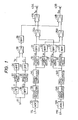
- Figure 5 is a block diagram of an embodiment of video and audio signal reproducing apparatus according to the invention;
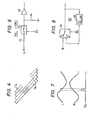
- Figure 6 is a schematic view of a drop-out compensator for use in an audio signal path, as might be used in the embodiment of Figure 5;
- Figure 7 is a waveform diagram to which reference will be made in explaining the operation of the apparatus of Figure 5;
- Figure 8 is a block diagram of a drop-out compensator, as might be used in a video path in the embodiment of Figure 5; and
- Figure 9 is a block diagram of another embodiment of video and audio signal reproducing apparatus according to the invention.
- Referring to Figure 1, a video and audio signal recording apparatus has audio
signal input terminals terminal 11L through an automatic gaincontrol amplifier circuit 12L, anoise reduction circuit 13L, and a pre-emphasis circuit 14L, in succession, to first andsecond frequency modulators terminal 11R through an automatic gaincontrol amplifier circuit 12R, anoise reduction circuit 13R, and apre-emphasis circuit 14R, in succession, to third andfourth frequency modulators - The
first frequency modulator 15 frequency modulates a carrier having a frequency fl, for example, of 1.325 MHz, by the left channel signal L to provide a frequency shift or deviation of the carrier of about 100 to 150 kHz, and to provide at the output of the frequency modulator 15 a frequency-modulated (FM) left channel signal or first FM audio signal LA. Thesecond frequency modulator 16 similarly frequency-modulates, by means of the left channel signal L,. a carrier having a frequency f2, for example, of 1.475 MHz, which is higher than the frequency f1 so as to provide at the output of thefrequency modulator 16 another FM left channel signal, or second FM audio signal LB, having the same frequency-shift deviation as the first FM audio signal LA, that is, a frequency deviation of about 100 to 150 kHz, but about a different central frequency. The third andfourth frequency modulators frequency modulators - The first and second or left FM audio signals LA and LB and the third and fourth or right FM audio signals RA and RB are passed from the
modulators pass filters - Referring once again to Figure 1, the left FM signal LA, representing the first FM audio signal from the band-
pass filter 21, and the right FM signal RA, representing the third FM audio signal from the band-pass filter 23, are supplied to amixing amplifier 25A, while the left FM signal LB from the band-pass filter 22 and the right FM signal RB from the band-pass filter 24 are supplied to amixing amplifier 25B. The output of the mixingamplifier 25A, that is, the first FM audio signal LA combined with the third FM audio signal RA, is supplied to asubsequent mixing amplifier 41A for mixing with the video signal, as will be described hereinafter. Similarly, the mixed output of the mixingamplifier 25B that is, the second FM audio signal LB combined with the fourth FM audio signal R8, is supplied to a mixingamplifier 41B that also has the video signal supplied thereto. The video signals supplied to the mixingamplifiers - The composite colour video signal formed of the FM luminance signal and the frequency-converted chrominance signal may be provided by a simplified video signal processing circuit as shown in Figure 1, including an
input terminal 31 that receives a colour video signal V containing both luminance and chrominance components. A low-pass filter 32 receives the colour video signal V from the terminal 31 and separates the luminance component Y from the composite signal. The luminance component is then passed through afrequency modulator 33 in which a carrier with a selected central frequency is frequency modulated by the luminance component Y to provide the FM luminance component that is then passed through a high-pass filter 34 and fed to an input of a mixingamplifier 38. The other input of the mixing-amplifier 38 is the chrominance component CL that is also derived from the composite video signal appearing at the terminal 31. Specifically, the colour video signal V supplied to the terminal 31 is fed to a band-pass filter 35 that separates the chrominance component Co from the colour video signal and passes the chrominance component through afrequency converter 36 in which the chrominance component is converted to a frequency band lower than that of the FM audio signals applied to the mixingamplifiers - The resulting frequency-converted chrominance component is supplied through a low-
pass filter 37 to the other input of the mixingamplifier 38 to which is also supplied the FM luminance component Y F* The output of the mixingamplifier 38 is fed through a band-pass filter 39, which acts as a "trap filter" to suppress the frequency band wherein the audio signals would lie, that is, the band-pass filter 39 passes only that part of the frequency spectrum that would contain the luminance and chrominance signal portions of the video signal. The output of the band-pass filter 39 is then fed to the mixingamplifiers amplifiers amplifiers magnetic heads amplifiers - In a helical scan VTR, the magnetic record medium is in the form of a magnetic tape, which is guided in a helical path about a substantial portion of the periphery of a guide drum, and the
heads heads head 43A scans alternate oblique tracks TA while thehead 43B scans the remaining alternate tracks TB. Usually, but not necessarily, each of the tracks TA and TB has recorded therein the video signal information corresponding to a respective field interval of the video signal. Since theheads heads 43A and 438, each of theheads respective head - In order to permit the alternating tracks TA and TB, as shown in Figure 4, to be distinguished from one another during reproduction, there is typically provided a control signal that is simultaneously recorded on the tape. The signal is typically derived from the vertical sync signals that are a part of the composite video signal supplied to the
input terminal 31. These control signals based on the vertical sync signals are detected during reproduction and are used to identify the tracks TA and TB, as to which signals were recorded by theheads - Referring to Figure 2, it is seen that the frequency f of the colour sub-carrier of the frequency-converted chrominance signal CL has a sufficiently low value, for example, 688 kHz, so that the resulting low frequency band of the chrominance signal CL will be below the band of the first FM audio signal LA having the above-mentioned central frequency f of 1.325 MHz. Additionally, when the frequency-converted chrominance signal CL and the FM luminance signal YF constituting a composite colour video signal are to be recorded along with the FM audio signals LA, LB, RA and RB in oblique tracks TA and TB, respectively, the central frequency of the carrier to be modulated by the lumiance component YF in the
frequency modulator 33 of Figure 1, is selected so that in the resulting FM luminance signal YF, the sync signal of the luminance component corresponds to a frequency which is substantially higher than the central frequency f4 of the fourth audio signal RB, while the maximum amplitude of the luminance component corresponds to a frequency that is higher than the frequency of the sync signal of the luminance component. In Figure 2 it will be noted from the value of the chrominance sub-carrier frequency fc and the relatively higher frequency of the FM luminance signal YF, that the resulting composite colour video signal to be recorded in the tracks TA and TB, has a space or blank in its spectrum between the chrominance signal and the luminance signal sufficient to accommodate all four of the FM audio signals LA LB, RA and RB. - As will also be noted from Figure 2, the amplitude level of the frequency-converted chrominance signal CL is selected to be larger than the levels of all of the FM audio signals LA, LB, RA and RB, and the amplitude level of the FM luminance signal YF is selected to be larger than the amplitude level of the chrominance signal CL. Additionally, it will be appreciated that the four FM audio signals are located close to one another in the space between the bands of the frequency-converted chrominance signal CL and the FM luminance signal YF, to minimize the space needed between the chrominance and luminance signals of the composite video signal to accommodate the four FM audio signals LA, LB, RA and RB.
- Figure 3 shows the spectrum of the signal SA as supplied to the
recording head 43A. Specifically, it is seen that only the first FM audio signal LA and the third FM audio signal RA are present in the space that has been intentionally left between the chrominance signal CL and the luminance signal YF. Similarly, Figure 3 shows the signal SB produced by theamplifier 41B as supplied to therecording head 43B and including only the second FM audio signal LB and the fourth FM audio signal RB arranged in the space between the chrominance signal CL and the luminance signal YF. - The manner in which the signals recorded by the apparatus of Figure 1 are reproduced will be described with reference to Figure 5 in which a reproducing apparatus is shown to include rotary
magnetic heads heads head 43A scans an oblique track TA and, during the next field, theother head 43B scans the adjacent oblique track TB, thus, thehead 43A mainly reproduces the first mixed signal SA, from the scanned track TA with the frequency spectrum shown in the upper portion of Figure 3, and the second mixed signal SB having the frequency spectrum shown in the lower portion of Figure 3 is mixed therewith only as a cross-talk component from the adjacent tracks TB. On the other hand, thehead 43B mainly reproduces the second mixed signal SB from the track TB being scanned and having the frequency spectrum of the lower portion of Figure 3, while the first mixed signal SA is mixed therewith only as a cross-talk component from the adjacent tracks TB. - The outputs from the
heads amplifiers pass filters head 43A are reproduced from the same track TB, the frequency bands of the signals LA and RA are spaed apart from each other, that is, they are not immediately adjacent, as is seen from the upper portion of Figure 3, so that the FM audio signals LA and RA can be satisfactorily separated from each other by the band-pass filters pass filters head 43B as obtained from theamplifier 44B is supplied to band-pass filters head 43B are also reproduced from the same track TA, their frequency bands are spaced apart from each other, as seen in the lower portion of Figure 3, and such signals can effectively be separated from each other by the band-pass filters pass filters - The left FM signals LA and LB and the right FM signals RA and RB obtained from the band-
pass filters pass filters amplitude limiters corresponding FM demodulators frequency demodulators pass filters pass filters frequency demodulators heads - In view of the specific selection of the differences between the adjacent carrier frequencies, for example, 150 kHz, and the specific filtering described above, portions of the reproduced left channel signal SA, without any components of the right channel signal SB or any beat noises mixed therewith, are provided at the outputs of the low-
pass filters pass filters - The alternating portions of the reproduced left channel signal obtained from the low-
pass filters switch circuit 67L, which is changed over at each alternating video field period in response to a control signal SW that is applied to the tape as described hereinabove and is based upon the vertical sync signal, so that a reconstituted, continuously reproduced, left channel signal SA is obtained at the output of theswitch 67L. This control signal SW is characterized as a rectangular pulse wave. Similarly, the alternating portions of the right channel signal obtained from the low-pass filters switch circuit 67R under the control of the switch control signal SW, so that a reconstituted continuously reproduced, right channel signal SB is obtained at the output of theswitch circuit 67R. In prior systems of this kind, the combined signals are passed throughde-emphasis circuits pre-emphasis circuits 14L and 14R in the recording apparatus of Figure 1 and include low-pass filters (not shown). The resulting left and right channel audio output signals are then supplied toaudio output terminals - In order to compensate for the adverse effects of randomly occurring drop-outs, as detected by a drop-
out detector 76, one embodiment of the invention provides a drop-out compensator in each of the left and right audio channels. Specifically, a drop-out compensator (or noise eliminator) 70L is provided between the output of the signal combiningswitch circuit 67L and the input of thede-emphasis circuit 68L and is responsive to the output of the drop-out detector 76. A second drop-out compensator (or noise eliminator) 70R is provided in the right channel between the output of theswitch circuit 67R and the input of thede-emphasis circuit 68R and is also responsive to the output signal from the drop-out detector 76. The manner in which the drop-out compensators - The reproduced signals from the
heads 43A and 438 and the reproducingamplifiers 44A and 448, respectively, are combined and processed in video signal processor circuitry in keeping with the video processor of Figure 1. The two signals corresponding to the alternating tracks are combined at aswitch circuit 75, which is similar in function to theswitch circuits switch circuit 75 is controlled by the signal Sw, derived from the vertical sync signal, for example, and the composite video signal that is combined by theswitch circuit 75 is available for video signal processing. Prior to signal processing, however, the drop-out detector 76 is connected to the composite video signal. The drop-out detector 76 may be any one of the several known kinds of detector, and in one embodiment of the invention the drop-out detector 76 is one in which the composite video signal is compared with a known reference level signal to detect drop-outs that are manifested by a loss of signal. The reference signal level can be varied to control the sensitivity of the drop-out detector 76. The output from the drop-out detector 76 is then fed to the drop-out compensators out compensators - One example of a drop-
out compensator switch circuits resistor 71, and through a normally closedswitch 72, to the input of abuffer amplifier 73. A holdingcapacitor 74 is connected between the audio input signal to thebufer amplifier 73 and ground. The charge on thecapacitor 74 will track the audio signal levels as presented to the input of thebuffer amplifier 73. When a drop-out is detected by the drop-out detector 76, a drop-out compensator control signal So is produced and fed to the drop-out compensators switch 72 to open. When theswitch 72 is opened, the audio signal fed to thebuffer amplifier 73 is interrupted and the only input to thebuffer amplifier 73 is derived from the voltage stored in thecapacitor 74 at that specific instant. Thecapacitor 74 discharges into the input of thebuffer amplifier 73 and, as will be shown below in relation to Figure 7, maintains the preceding instantaneous signal level substantially constant. - The operation of the drop-
out compensators out compensator 70L, and the middle waveform R represents the audio signal out of the drop-out compensator 70R. The lowermost waveform So in Figure 7 represents the compensation control signal from the drop-out detector 76. The effects of thecapacitor 74 in maintaining an instantaneous signal level substantially constant are readily seen in the upper two waveforms of Figure 7. Additionally, as may be seen in Figure 7, the length of time that a drop-out exists is small in comparison to the period of the audio signals and, thus, by smoothing the audio signals and avoiding discontinuities, the adverse effects of drop-out in the audio signals are substantially eliminated. - Returning to Figure 5, the combined first and second mixed signals appearing at the output of the
switch circuit 75 contain all of the video signal information that was previously recorded on the tape, as described above with reference to Figure 1. The video signal information is first separated from the combined first and second mixed signals by a band-pass filter 77 that has a frequency response similar to a trap filter to remove all audio frequency components from the combined first and second mixed signals. The video signal must then be separated into the luminance and chrominance components, the luminance component is separated from the combined video signals by a high-pass filter 81 to produce the frequency-modulated luminance component Y F. The frequency modulated luminance component Y F is then typically amplitude limited in anamplitude limiter 82 and then frequency demodulated in afrequency demodulator 83. The demodulated luminance component of the video signal is then passed through a low-pass filter 84 and made available at a terminal 89Y for display. The chrominance component is removed from the combined video signal by a low-pass filter 85 to form the chrominance component signal CL. Because the chrominance component had been previously down converted in frequency, it must now be converted back up and this is accomplished in afrequency converter 86. The frequency-converted chrominance component is then filtered in a band-pass filter 87. - Additionally, as described hereinabove, the chrominance component of the video signal was recorded in a special fashion, specifically, each of the line areas or increments of one track may have recorded therein a frequency converted chrominance signal component with a carrier of constant polarity, whereas in the next adjacent tracks, the carrier of the frequency-converted chrominance signal component recorded therein reverses its polarity for successive line intervals. Such pattern of recording ensures that during reproduction cross-talk effects can be minimized or eliminated. During reproduction of the recorded signals, the reproduced signals of two successive line intervals can be added together by means of suitable delay means or by a
simple comb filter 88 to cancel out or minimize cross-talk interference signals associated with the desired reproduced signals of the two successive line intervals. The combiningcomb filter 88 in Figure 5 produces the chrominance signal at anoutput terminal 89C. Drop-outs can also adversely affect the video signal, and specifically, can adversely affect the luminance portion of the video signal, since it contains the majority of the video signal information. This embodiment of the invention therefore uses an additional drop-out compensator arranged in the chrominance component path of the video processor. A video drop-out compensator (or noise eliminator) 90 is again responsive to the compensator control signal SD that initiates drop-out compensating action in the audio drop-out compensators - The drop-
out compensator 90 for use in the luminance component of the video signal is shown in more detail in Figure 8, wherein the luminance signal YF is supplied to a normal terminal N of aswitch circuit 91 that, in its normal state, provides the input luminance component YF to its output. Theswitch circuit 91 is responsive to the output signal SD of the drop-out detector 76, to switch between the luminance signal Y F at a terminal N and a D terminal that has connected thereto a delayed feedback from the output of theswitch circuit 91 when the normal input terminal N is connected to the output. More specifically, the chrominance signal Y F output from theswitch circuit 91, when the N input is connected to the output, is fed back through a one horizontal scan line (1 H)delay unit 92 to the delay input D of theswitch 91. In the operation of the video drop-out compensator 90 of Figure 8, used in the chrominance component path of the video signal, upon the drop-out detector 76 detecting a drop-out and providing a control signal SD that is fed to theswitch circuit 91, theswitch circuit 91 moves off its normal position at the terminal N, wherein the modulated luminance component YF is fed through theswitch circuit 91 and to the input of theamplitude limiter 82, and theswitch circuit 91 moves to connect the input terminal D to its output. The feedback. signal that then comprises the output signal is delayed by the one horizontal frame delay provided by thedelay unit 92. Theamplitude limiter 82 then receives at its input the same scan line that had been fed to it in the preceding scan, thereby eliminating adverse effects caused by a drop-out that typically results in white lines on the video screen. - Turning now to Figure 9, another embodiment of a reproducing apparatus similar to that of Figure 5 is shown, except that the arrangement in the circuit of the drop-out detector is modified. In the embodiment of Figure 9, drop-outs are detected by the drop-
out detector 76 in the frequency-modulated audio signal R A which is separated from the first mixed signal by the band-pass filter 53, and the drop-out detector 93, which can be constructed as described hereinabove is connected to this separated signal. This provides a drop-out detection of only one of the alternating tracks that have been recorded and, thus, it is necessary to detect drop-outs in the other alternating tracks. This detection is accomplished by connecting a second drop-out detector 94 to receive the fourth frequency modulated audio signal RB as filtered out by the band-pass filter 54. The outputs from the drop-outdetectors gate 95 that produces the drop-out control signal So which is fed to the audio drop-out compensators out compensator 90 located in the luminance component signal YF path, as separated by the high-pass filter 81. - In another alternative embodiment shown in Figure 9, the drop-out detector may be located in the luminance component signal YF line and still serve to detect all drop-outs in both of the alternating pairs of tracks. Specifically, after the first and second mixed signals produced by the
heads 43a and 43B and amplified in reproducingamplifiers switch circuit 75, and the video portion thereof separated by the band-pass filter 77, the luminance component YF is further separated from the video signal by the high-pass filter 81. The drop-out detector 96 is connected to the luminance signal YF path, as shown by the dashed lines, to indicate that the drop-out detector 96 is not in addition to the other detectors but is an alternative embodiment. The output of the drop-out detector 96 then becomes the drop-out control signal So that is supplied to the audio drop-out compensators out compensator 90 located in the luminance component signal YF path.
Claims (12)
Priority Applications (1)
| Application Number | Priority Date | Filing Date | Title |
|---|---|---|---|
| AT83300703T ATE30097T1 (en) | 1982-02-13 | 1983-02-11 | DEVICE FOR PLAYBACK OF VIDEO AND AUDIO SIGNALS. |
Applications Claiming Priority (2)
| Application Number | Priority Date | Filing Date | Title |
|---|---|---|---|
| JP57021695A JPS58139575A (en) | 1982-02-13 | 1982-02-13 | Reproducer of video signal and sound signal |
| JP21695/82 | 1982-02-13 |
Publications (3)
| Publication Number | Publication Date |
|---|---|
| EP0087249A2 true EP0087249A2 (en) | 1983-08-31 |
| EP0087249A3 EP0087249A3 (en) | 1984-08-08 |
| EP0087249B1 EP0087249B1 (en) | 1987-09-30 |
Family
ID=12062195
Family Applications (1)
| Application Number | Title | Priority Date | Filing Date |
|---|---|---|---|
| EP83300703A Expired EP0087249B1 (en) | 1982-02-13 | 1983-02-11 | Apparatus for reproducing video and audio signals |
Country Status (5)
| Country | Link |
|---|---|
| US (1) | US4651230A (en) |
| EP (1) | EP0087249B1 (en) |
| JP (1) | JPS58139575A (en) |
| AT (1) | ATE30097T1 (en) |
| DE (1) | DE3373968D1 (en) |
Families Citing this family (15)
| Publication number | Priority date | Publication date | Assignee | Title |
|---|---|---|---|---|
| JPS59160806A (en) * | 1983-03-02 | 1984-09-11 | Mitsubishi Electric Corp | Dropout compensating circuit |
| JPS6386980A (en) * | 1986-09-30 | 1988-04-18 | Toshiba Corp | Preiodic noise eliminating device |
| US4864427A (en) * | 1986-12-22 | 1989-09-05 | Pioneer Electronic Corporation | Disk reproducing method and apparatus for disks with different video bandwidths |
| US5031218A (en) * | 1988-03-30 | 1991-07-09 | International Business Machines Corporation | Redundant message processing and storage |
| KR910009144Y1 (en) * | 1988-04-07 | 1991-11-25 | 삼성전자 주식회사 | F.m. signal transferring and recording system for vcr |
| US5124807A (en) * | 1988-08-09 | 1992-06-23 | Go-Video, Inc. | Dual deck videocassette recorder system |
| US5194963A (en) * | 1988-08-09 | 1993-03-16 | Go-Video, Inc. | Dual deck videocassette recorder system |
| JPH02137595A (en) * | 1988-11-18 | 1990-05-25 | Sony Corp | Detection circuit for drop-out |
| US5059387A (en) * | 1989-06-02 | 1991-10-22 | Megamet Industries | Method of forming shaped components from mixtures of thermosetting binders and powders having a desired chemistry |
| JPH04140084A (en) * | 1990-09-28 | 1992-05-14 | Copal Electron Co Ltd | Defective start-up detection circuit for dc motor |
| US5644447A (en) * | 1991-03-01 | 1997-07-01 | Canon Kabushiki Kaisha | Recording or reproducing apparatus having function of searching for unrecorded part |
| JPH04361493A (en) * | 1991-06-07 | 1992-12-15 | Canon Inc | Video signal reproduction device |
| US5946442A (en) * | 1995-09-26 | 1999-08-31 | Samsung Electronics Co., Ltd. | High-speed video tape copier |
| US6310660B1 (en) | 1998-03-18 | 2001-10-30 | Sony Corporation | Video signal dropout detector |
| JP2010277624A (en) * | 2009-05-26 | 2010-12-09 | Toshiba Storage Device Corp | Magnetic recording device, head evaluation device, spin stand device, and write pole erasure evaluation method |
Citations (5)
| Publication number | Priority date | Publication date | Assignee | Title |
|---|---|---|---|---|
| DE1277900B (en) * | 1965-03-23 | 1968-09-19 | Loewe Opta Gmbh | Method for the magnetic recording and reproduction of high-frequency signals, in particular television picture signals, as well as audio and / or synchronous signals |
| DE2201691A1 (en) * | 1972-01-14 | 1973-07-26 | Blaupunkt Werke Gmbh | METHOD OF SIMULTANEOUS RECORDING AND REPLAY OF COLOR TELEVISION SIGNALS |
| US3989893A (en) * | 1974-09-13 | 1976-11-02 | U.S. Philips Corporation | Reproducing apparatus with drop out suppression circuit for audio and video signals |
| US4245262A (en) * | 1978-08-03 | 1981-01-13 | Matsushita Electric Industrial Co., Ltd. | Dropout compensating device |
| EP0044687A1 (en) * | 1980-07-14 | 1982-01-27 | Hitachi, Ltd. | Noise elimination circuit in a magnetic recording and reproducing apparatus |
Family Cites Families (13)
| Publication number | Priority date | Publication date | Assignee | Title |
|---|---|---|---|---|
| NL177168C (en) * | 1972-09-02 | 1985-08-01 | Philips Nv | METHOD FOR RECORDING A VIDEO SIGNAL AND RECORD CARRIER WITH VIDEO INFORMATION RECORDED ACCORDING TO THE METHOD AND AN APPARATUS FOR READING A RECORD CARRIER. |
| JPS5430848B2 (en) * | 1975-02-20 | 1979-10-03 | ||
| JPS51143310A (en) * | 1975-06-03 | 1976-12-09 | Mitsubishi Electric Corp | Information regenerating system |
| JPS5823998B2 (en) * | 1977-03-08 | 1983-05-18 | 日本ビクター株式会社 | Information signal recording method |
| JPS567213A (en) * | 1979-06-27 | 1981-01-24 | Hitachi Ltd | Noise eliminating circuit |
| JPS5644285A (en) * | 1979-09-20 | 1981-04-23 | Matsushita Electric Ind Co Ltd | Video and sound signal recording device |
| JPS5741084A (en) * | 1980-08-25 | 1982-03-06 | Hitachi Ltd | Voice signal recording and reproducing device |
| JPS5746306A (en) * | 1980-09-03 | 1982-03-16 | Hitachi Ltd | Aural signal muting circuit of magnetic recorder and reproducer |
| JPS57150285A (en) * | 1981-03-12 | 1982-09-17 | Victor Co Of Japan Ltd | Magnetic recording system of sound signal and recording and reproducing system |
| JPS57152506A (en) * | 1981-03-16 | 1982-09-20 | Victor Co Of Japan Ltd | Magnetic recording system |
| DE3125879A1 (en) * | 1981-07-01 | 1983-01-20 | Licentia Patent-Verwaltungs-Gmbh, 6000 Frankfurt | VIDEO RECORDER WITH IMPROVED SOUND RECORDING |
| JPS58100205A (en) * | 1981-12-11 | 1983-06-14 | Sony Corp | Video and sound signal recording device |
| US4462048A (en) * | 1982-02-11 | 1984-07-24 | Rca Corporation | Noise reduction circuitry for audio signals |
-
1982
- 1982-02-13 JP JP57021695A patent/JPS58139575A/en active Pending
-
1983
- 1983-02-11 DE DE8383300703T patent/DE3373968D1/en not_active Expired
- 1983-02-11 EP EP83300703A patent/EP0087249B1/en not_active Expired
- 1983-02-11 AT AT83300703T patent/ATE30097T1/en not_active IP Right Cessation
- 1983-02-14 US US06/466,212 patent/US4651230A/en not_active Expired - Lifetime
Patent Citations (5)
| Publication number | Priority date | Publication date | Assignee | Title |
|---|---|---|---|---|
| DE1277900B (en) * | 1965-03-23 | 1968-09-19 | Loewe Opta Gmbh | Method for the magnetic recording and reproduction of high-frequency signals, in particular television picture signals, as well as audio and / or synchronous signals |
| DE2201691A1 (en) * | 1972-01-14 | 1973-07-26 | Blaupunkt Werke Gmbh | METHOD OF SIMULTANEOUS RECORDING AND REPLAY OF COLOR TELEVISION SIGNALS |
| US3989893A (en) * | 1974-09-13 | 1976-11-02 | U.S. Philips Corporation | Reproducing apparatus with drop out suppression circuit for audio and video signals |
| US4245262A (en) * | 1978-08-03 | 1981-01-13 | Matsushita Electric Industrial Co., Ltd. | Dropout compensating device |
| EP0044687A1 (en) * | 1980-07-14 | 1982-01-27 | Hitachi, Ltd. | Noise elimination circuit in a magnetic recording and reproducing apparatus |
Non-Patent Citations (1)
| Title |
|---|
| PHILIPS TECHNICAL REVIEW, vol. 33, no. 7, 1973, pages 181-185, Eindhoven, NL W. VAN DEN BUSSCHE et al.: "Signal processing in the Philips 'VLP' system" * |
Also Published As
| Publication number | Publication date |
|---|---|
| EP0087249A3 (en) | 1984-08-08 |
| US4651230A (en) | 1987-03-17 |
| EP0087249B1 (en) | 1987-09-30 |
| JPS58139575A (en) | 1983-08-18 |
| DE3373968D1 (en) | 1987-11-05 |
| ATE30097T1 (en) | 1987-10-15 |
Similar Documents
| Publication | Publication Date | Title |
|---|---|---|
| EP0087249B1 (en) | Apparatus for reproducing video and audio signals | |
| EP0084449B1 (en) | Apparatus for recording and/or reproducing video and audio signals | |
| EP0087811A1 (en) | Magnetic recording/reproducing apparatus | |
| US3846819A (en) | Method for recording two separate signals | |
| US4504869A (en) | Color moviola for two-track VTR | |
| US4464684A (en) | Video recorder providing transient-free audio signals | |
| CA1205187A (en) | Apparatus for reproducing video and audio signals | |
| US4134126A (en) | Color recorder having means for reducing luminance crosstalk in displayed image | |
| US4490751A (en) | Apparatus for recording and/or reproducing video and audio signals | |
| US4490753A (en) | Audio signal recording and reproducing circuit | |
| US4208673A (en) | Color recorder for reducing crosstalk | |
| US4492986A (en) | VTR With high-quality audio recording system | |
| US4175272A (en) | Video signal processing circuitry for compensating different average levels | |
| CA1159950A (en) | Signal reproducing circuit for a video tape recorder and particularly to a differential gain control circuit | |
| US3542946A (en) | Video recording and reproducing apparatus utilizing a single track on a magnetic tape for the luminance and color information components of a color television signal | |
| CA1205188A (en) | Apparatus for detecting and compensating drop-outs in an audio and video signal | |
| EP0177235B1 (en) | Apparatus for recording audio and video signals | |
| US4571639A (en) | Dropout compensation circuit for a video reproducing system | |
| JPH0466062B2 (en) | ||
| US5396372A (en) | Audio signal recording and reproducing apparatus | |
| JPH0427757B2 (en) | ||
| US4583130A (en) | AST for a two track VTR | |
| KR950007909Y1 (en) | Image recording reproducing device with exclusive head | |
| JPH0239917B2 (en) | ||
| JPH05266443A (en) | Magnetic recording and reproducing device |
Legal Events
| Date | Code | Title | Description |
|---|---|---|---|
| PUAI | Public reference made under article 153(3) epc to a published international application that has entered the european phase |
Free format text: ORIGINAL CODE: 0009012 |
|
| AK | Designated contracting states |
Designated state(s): AT DE FR GB NL |
|
| PUAL | Search report despatched |
Free format text: ORIGINAL CODE: 0009013 |
|
| AK | Designated contracting states |
Designated state(s): AT DE FR GB NL |
|
| 17P | Request for examination filed |
Effective date: 19841214 |
|
| 17Q | First examination report despatched |
Effective date: 19860616 |
|
| GRAA | (expected) grant |
Free format text: ORIGINAL CODE: 0009210 |
|
| AK | Designated contracting states |
Kind code of ref document: B1 Designated state(s): AT DE FR GB NL |
|
| REF | Corresponds to: |
Ref document number: 30097 Country of ref document: AT Date of ref document: 19871015 Kind code of ref document: T |
|
| ET | Fr: translation filed | ||
| REF | Corresponds to: |
Ref document number: 3373968 Country of ref document: DE Date of ref document: 19871105 |
|
| PLBE | No opposition filed within time limit |
Free format text: ORIGINAL CODE: 0009261 |
|
| STAA | Information on the status of an ep patent application or granted ep patent |
Free format text: STATUS: NO OPPOSITION FILED WITHIN TIME LIMIT |
|
| 26N | No opposition filed | ||
| REG | Reference to a national code |
Ref country code: GB Ref legal event code: IF02 |
|
| PGFP | Annual fee paid to national office [announced via postgrant information from national office to epo] |
Ref country code: FR Payment date: 20020212 Year of fee payment: 20 |
|
| PGFP | Annual fee paid to national office [announced via postgrant information from national office to epo] |
Ref country code: GB Payment date: 20020213 Year of fee payment: 20 Ref country code: AT Payment date: 20020213 Year of fee payment: 20 |
|
| PGFP | Annual fee paid to national office [announced via postgrant information from national office to epo] |
Ref country code: DE Payment date: 20020227 Year of fee payment: 20 |
|
| PGFP | Annual fee paid to national office [announced via postgrant information from national office to epo] |
Ref country code: NL Payment date: 20020228 Year of fee payment: 20 |
|
| PG25 | Lapsed in a contracting state [announced via postgrant information from national office to epo] |
Ref country code: GB Free format text: LAPSE BECAUSE OF EXPIRATION OF PROTECTION Effective date: 20030210 |
|
| PG25 | Lapsed in a contracting state [announced via postgrant information from national office to epo] |
Ref country code: NL Free format text: LAPSE BECAUSE OF EXPIRATION OF PROTECTION Effective date: 20030211 Ref country code: AT Free format text: LAPSE BECAUSE OF EXPIRATION OF PROTECTION Effective date: 20030211 |
|
| REG | Reference to a national code |
Ref country code: GB Ref legal event code: PE20 Effective date: 20030210 |
|
| NLV7 | Nl: ceased due to reaching the maximum lifetime of a patent |
Effective date: 20030211 |