EP0076883A1 - Blank for a tray - Google Patents
Blank for a tray Download PDFInfo
- Publication number
- EP0076883A1 EP0076883A1 EP81305876A EP81305876A EP0076883A1 EP 0076883 A1 EP0076883 A1 EP 0076883A1 EP 81305876 A EP81305876 A EP 81305876A EP 81305876 A EP81305876 A EP 81305876A EP 0076883 A1 EP0076883 A1 EP 0076883A1
- Authority
- EP
- European Patent Office
- Prior art keywords
- container
- flap
- base
- strut
- blank
- Prior art date
- Legal status (The legal status is an assumption and is not a legal conclusion. Google has not performed a legal analysis and makes no representation as to the accuracy of the status listed.)
- Withdrawn
Links
Images


Classifications
-
- B—PERFORMING OPERATIONS; TRANSPORTING
- B65—CONVEYING; PACKING; STORING; HANDLING THIN OR FILAMENTARY MATERIAL
- B65D—CONTAINERS FOR STORAGE OR TRANSPORT OF ARTICLES OR MATERIALS, e.g. BAGS, BARRELS, BOTTLES, BOXES, CANS, CARTONS, CRATES, DRUMS, JARS, TANKS, HOPPERS, FORWARDING CONTAINERS; ACCESSORIES, CLOSURES, OR FITTINGS THEREFOR; PACKAGING ELEMENTS; PACKAGES
- B65D5/00—Rigid or semi-rigid containers of polygonal cross-section, e.g. boxes, cartons or trays, formed by folding or erecting one or more blanks made of paper
- B65D5/001—Rigid or semi-rigid containers of polygonal cross-section, e.g. boxes, cartons or trays, formed by folding or erecting one or more blanks made of paper stackable
- B65D5/005—Separate or attached stacking elements
- B65D5/0065—Separate elements inserted in or attached to integral corner posts or ledges
-
- B—PERFORMING OPERATIONS; TRANSPORTING
- B65—CONVEYING; PACKING; STORING; HANDLING THIN OR FILAMENTARY MATERIAL
- B65D—CONTAINERS FOR STORAGE OR TRANSPORT OF ARTICLES OR MATERIALS, e.g. BAGS, BARRELS, BOTTLES, BOXES, CANS, CARTONS, CRATES, DRUMS, JARS, TANKS, HOPPERS, FORWARDING CONTAINERS; ACCESSORIES, CLOSURES, OR FITTINGS THEREFOR; PACKAGING ELEMENTS; PACKAGES
- B65D5/00—Rigid or semi-rigid containers of polygonal cross-section, e.g. boxes, cartons or trays, formed by folding or erecting one or more blanks made of paper
- B65D5/42—Details of containers or of foldable or erectable container blanks
- B65D5/44—Integral, inserted or attached portions forming internal or external fittings
- B65D5/441—Reinforcements
- B65D5/443—Integral reinforcements, e.g. folds, flaps
Definitions
- the present invention relates to a blank of foldable sheet material for erection into a container and to a container made from such a blank.
- a container must be suitable for maintaining the quality of the packaged goods. There is the additional requirement that best use is made of the available volume, because of increasingly high transport costs. Accordingly, boxes for packing fragile goods, for instance, food produce such as tomatoes or mushrooms, should be as large as possible yet not so large that the lowermost layers of the commodity are crushed by those above. This is particularly important for high quality, grade A food produce, such as tomatoes or mushrooms.
- the containers For optimum use of the available space when transporting such food produce, it is desirable for the containers, individually limited in their volume, to be stackable one above the other, the lower containers in the stack being able to bear the load of packed containers above.
- the number of containers which can be stacked in this way is determined by the strength of the lowermost box in the stack. For conventional cardboard boxes which package tomatoes, the stack will be approximately twelve boxes high. In addition to the weight of the packed boxes above it, the lowermost box must be strong enough to withstand the vibrations of the vehicle on which the stack of containers is transported.
- containers for packaging tomatoes and the like are erectable from a flattened, collapsed state.
- Known containers suffer from the problem that if the boxes are strong enough to stack then they will be of rigid construction and not able to be erected from a flattened, collapsed state. This is a disadvantage since the empty boxes, sent to food produce packers, will take up an excessive amount of space. It is clearly desirable for the empty boxes to be delivered in a collapsed, substantially flat state from which the box may readily be erected for filling with the food produced.
- a collapsible box once opened to receive food produce, clearly must not return readily to its collapsed state when it is stacked, if the packed food produce is not to be crushed.
- a blank of foldable sheet material intended for erection into a container, comprising a central, substantially rectangular portion for forming the base of the container, and panels hingedly connected by first fold lines extending along the edges of at least three sides of said central portion for erection to form side walls of the container, at least one of said panels being provided with a flap extending from and hinged to an end thereof, said flap being provided with at least one second fold line extending substantially parallel to said hinge, whereby the flap may be folded to form a load-bearing corner strut which can be located within the base of the container when the container is erected.
- the blank is made from a single sheet of material, the said central portion, the panels and said at least one flap being integral, the hinge between the or each flap and its respective panel comprising a fold line in the sheet of material.
- the blank lends itself to simple and therefore economic assembly into a container.
- the hinge between said at least one flap and the panel to which it is connected extends approximately perpendicular to the first fold line of the respective panel, and the flap has a series of spaced second fold lines extending substantially parallel to the hinge and dividing the flap into a plurality of sections, whereby, on folding said flap about the hinge and the second fold lines, the load-bearing strut is formed.
- the or each strut is collapsible in shear, by folding it about the hinge and/or the second fold lines to flatten the sections against each other.
- the blank may be erected to form a container which can be flattened or opened.
- At least one of the sections forming the flap extends substantially to the imaginary projection of the first fold line to form a foot portion, whereby, on folding the flap about the hinge and the second fold lines to form the strut, a strut of hollow section is formed, the flap sections forming walls of the hollow strut, and the foot portion being able to abut.-. the base of the container when the respective panel is folded about the first fold line to form a side wall of the container.
- the load borne by the or each strut when the container is supporting another such container in a stack can be transmitted to and therefore spread throughout the base of the container.
- Such a flap may, for instance, be divided by the said second fold lines into four sections, whereby the flap can be folded into a strut of quadrilateral hollow section.
- a slit is preferably provided in the first fold line hingedly connecting the or each panel having a flap to the base, said slit being openable to receive therethrough the foot portion of the strut when the side wall formed by that panel is folded inwardly to lie against the base of the container.
- the panel adjacent that panel having the flap is preferably adapted to be connected to one of the flap sections when the container is erected.
- the panel adjacent the panel having the flap is preferably provided, at that end adjacent the flap, with the fold line angled with respect to its first fold line to delineate a foldable corner portion of the panel, whereby, when interconnected, the side walls formed by the said two panels are foldable generally inwardly about their first fold lines to lie against the base of the container, thus flattening it, with said corner portion being folded outwardly.
- a panel is provided on each of the four sides of the central portion, the panels of one pair of opposite panels being provided with a flap hingedly connected at each of their ends, the other pair of panels having no flaps.
- the flap extends in a direction perpendicular to its fold lines beyond the overall width of that adjacent panel to which it is not connected. This facilitates the operation carried out by mechanical handling apparatus in an assembly line making up containers from such blanks, where the apparatus has to pick up the flap in preference to the panel and fold that flap about the hinge and second fold lines to form a strut.
- each flap For making a container having side walls substantially vertically upstanding from the base, the hinge of each flap extends substantially perpendicular to the respective first fold line.
- each flap extends at an obtuse angle to the respective first fold line, whereby, on folding said panels about their first fold lines to form the side walls and connecting adjacent side walls to one another, a container having outwardly flared side walls is formed.
- At least some of the sections of the or each flap extend, in a direction parallel to said second fold lines, outwardly from said central portion, less far than the maximum extent of the adjacent portion of the panel to which it is hingedly connected, whereby, on folding the or each flap about its hinge and second fold lines, a strut which is shorter than the adjacent portion of the side wall is formed.
- a container made from a blank of foldable sheet material, comprising a base and at least three side walls upstanding from the base and extending along corresponding edges of the base, and at least one load-bearing corner strut formed integrally from the blank and disposed at an angle enclosed between two of said side walls.
- said at least one strut is collapsible between a position in which it lies substantially flat against the base and a position in which it is upstanding from the base, whereby the container is erectable from a collapsed, substantially flat state into an open state, in which open state the container may be stacked on like containers, the container being supported by the corner strut or struts of the container below it in the stack.
- the or each corner strut is of open hollow section.
- the side walls are hingedly connected to the edges of the base and to an adjacent side wall, a slit being provided in each hinge connection adjacent each corner strut, to receive therethrough a lower end portion of the strut when it is in its position lying against the base.
- the slit allows the lower end portion of the strut to pass through it, instead of pressing into the hinge between the side wall and the base thus crumpling the material either side of the hinge.
- the container side walls may be substantially vertically upstanding from the base or may be at an obtuse angle thereto to form a container having outwardly flaring side walls. This latter form is useful where enhanced ventilation of the packaged goods, e.g. mushrooms, in the stacked containers is desirable.
- the corner struts are preferably shorter than the height of the adjacent portions of the side walls, whereby the containers may be positively located one above another, by being disposed to sit partially within one another, the base of one container being retained within the corners of the container below. Furthermore, there is the advantage that there is no need to provide lids for these stacked containers, the base of one container acting as the lid for the container below; only the topmost container requires a lid.
- the container further comprises a post for the or each hollow corner strut, each post having an outer cross-sectional dimension substantially equal to the inner cross-sectional dimension of the hollow strut, whereby the post can be received within the corresponding hollow corner strut with friction fit.
- the posts are inserted into corresponding hollow corner struts and may provide some additional rigidity for the strut.
- the posts are longer than the height of the corner struts and a hole is provided in the base below each corner strut, so that the posts received within the corner strut extend through the base of the container, whereby the posts of adjacent containers in a stack of containers can rest on one another when the containers are stacked on one another.
- the posts when the posts have been inserted into the corner struts, the lower ends of the posts project through the base of the container to rest on the posts of the container below in the stack.
- the posts preferably have interengagement means at their ends, whereby the posts can fit together end to end.
- the containers interengage one another when the containers are stacked, thereby forming a stable stack in which no container lids are required, apart from the topmost container in the stack.
- the posts may be inserted into the struts either from above or from below. When they are inserted from below a flange may be provided on the post, against which flange the base of the container abuts.
- Figures 1 and 2 illustrate a blank and Figure 3 a container respectively in accordance with one embodiment of the invention.
- the blank of Figures 1 and 2 generally comprise a central portion 10 and panels connected around all four edges of the central portion.
- the panels are arranged in opposite pairs 12 and 14 and are hingedly connected along respective first fold lines 16, 18.
- Each of the four flaps 20 is divided into four section 24 1 , 24 2 , 24 3 and 24 4 by a series of substantially parallel second fold lines 26.
- Each of the two panels 12 which does not have flaps 20 extending therefrom is provided with a pair of fold lines 28 disposed at an angle to the fold lines 16 along which the panel 12 is hinged to the central portion of the blank. These fold lines delineate corner portion 29 of the panels 12.
- L-shaped slits 30 are cut in the blank, at least one limb of the slit lying along the first fold line 18 along which the panels 14 are hinged to the central portion 10. There is provided a slit 30 for each respective flap 20. Thus, in this embodiment, there are four slits 30.
- the blank is made from a single sheet of material, the blank being cut according to the outer perimeter as shown in Figure 1, the slits 30 being cut simultaneously or subsequently to cutting the outline of the blank. Similarly, apertures 32 are cut into the panels 12 and 14 either simultaneously or subsequently.
- the first fold lines 16 and 18, as well as the second fold line 26 in the panels 20 and the fold lines 28 in the panels 12 are then creased into the blank, either by pressing or rolling.
- the container shown in Figure 3 may be made from the blank shown in Figures 1 and 2 in the following way.
- the blank is passed longitudinally along an assembly line in the direction of arrow A ( Figure 1).
- each of the four flaps 20 is folded in half about its central second fold line 26' in the direction of arrow B so that the two outermost sections of each flap 24 1 and 24 2 overlie the two innermost sections 24 4 and 24 3 respectively.
- a flap folded in this way is shown at the left top hand corner of Figure 2.
- the underside of section 24 1 which is now uppermost then has adhesive applied thereto by rollers or other known means.
- the next step is to fold the flaps 20 again, this time about their hinge 22 in the direction of arrow C ( Figure 2) into the position shown in the lower left hand corner of Figure 2, the flap then lying against the panel 14 and section 24, previously coated with adhesive, adheres to panel 14. Section 24 4 of each flap then has adhesive applied thereto.
- FIG. 2 shows flaps at different positions, it is to be understood that on the assembly line the left hand pair of flaps, as viewed in Figures 1 and 2 are first manipulated by the mechanical handling apparatus to fold them in half and then simultaneously folded once more about their hinges 22, the blank then advancing along the line until the mechanical handling apparatus performs the same two consecutive operations on both of their right hand flaps, as viewed in Figures 1 and 2.
- the flaps 20 extend beyond the full width of panels 12, so that it is easier for the mechanical handling apparatus to pick and fold the flaps 20 in preference to the panels 12.
- the panels 12 which are now free of the flaps 20 are folded about their first fold lines 16 to lie against the central portion 10 of the blank and one of the panels 12 folded in this way is shown at the bottom of Figure 2. In practice, of course, both these panels will be folded about their fold lines 16 simultaneously.
- the corner portions 29 of the panels 12 are then folded back, as shown in Figure 2 and, again, all four corner portions are folded back simultaneously.
- the blank is then turned through 90° for the mechanical handling apparatus to grasp the panels 14 and fold them about the fold lines 18 so that the sections 244, coated with adhesive, are brought into contact with the corner portions 29 of panels 12. If contact adhesive is used throughout, there is no need for pressure to be applied to adhere section 24 1 to panel 14 and section 24 4 to the corner portion 29 of panel 12.
- a container in a flat, or collapsed state has now been formed and all that is required is for the panels 12 and 14 to be raised up away from the central portion 10 to form the open container shown in Figure 3.
- the panels 12 and 14 will stand at right angles to form side walls of the container perpendicular to the central portion 10 which acts as the base of the container.
- Each of the flaps 20 forms an open, hollow section strut 40 which abuts the base 10 and acts as a load-bearing member so that the container is capable of bearing considerable loads.
- the struts 40 thus enable the container to be stacked.
- Each of the flaps extend as far as an imaginary extension of the fold line 18 hingedly connecting its respective panel 14 to the central portion to form a foot portion 34. It is necessary for the flap to extend this far in this direction so that, when folded to form the strut 40, the strut will be able to abut the base 10 of the container thereby transmitting load carried by the strut to the base of the container. It thus ensures that the container once opened up into the state shown in Figure 3 will not collapse to crush produce packaged within the container, as well as spreading load through the base.
- slots 30 in the fold lines 18 is to receive the foot portions of the strut when the box is in its collapsed, flat state so that the foot portions 34 do not press into the fold lines 18, thus damaging the material either side of those fold lines. The strength and neat appearance cfthe container is thus maintained.
- the apertures 32 in the side walls 12, 14 act as ventilation holes and/or carrying holes for the container.
- Figures 4 and 5 relate to a second embodiment of the invention, illustrating a blank and a container made from such a blank respectively.
- the blank shown in Figure 4 is much the same as that shown in Figure 1, with the exception that the flaps 20 are provided as extensions hingedly connected to the longer panels 12, rather than to the shorter panels 14. Panels 14 are instead provided with the fold line 28, which enable the container to be collapsed.
- Figures 6 and 7 relate to a third embodiment of the invention and illustrate how a container having outwardly flared side walls can be formed.
- a container is particularly useful where enhanced ventilation of a packaged commodity, such as mushrooms, is required, when the containers are stacked one on top of each other.
- the hinges 22 are angled with respect to the first fold lines 18 and the intersection 36 cut between the flaps 20 and adjacent panels 12 is angled with respect to the first fold line 16, whereby the side walls 12, 14 may be joined in such a way as to form a container having outwardly flared side walls.
- Figures 8 and 9 relate to a further form, in which the blank is so shaped to give, in the erected container, a height difference between the struts 40 and those portions of the side walls 12 and 14 adjacent the struts, so as to provide locating means for locating the base 10 of a container which is stacked above, and rests on the struts 40 of that container.
- sections 24 2 and 24 3 are made shorter than adjacent sections 24 1 and 24 4 of the flap 20, whereby a recessed strut 40, which is less high than the depth of those portions of the side walls 12 and 14 adjacent the strut, may be formed.
- a stack of such containers is particularly stable and has an added advantage that individual lids for the containers are not necessary, as the base 10 of one container acts as the lid for the container below it. Only the top container in the stack needs a lid.
- section 24 1 of the flap 20 may be co-extensive with sections 24 2 and 243, as it does not have to be flush with the top edge of the side wall 12 in the erected container.
- section 24 2 should, in all cases, be co-extensive with the respective section 243, so that both sections reach to the same height above the base 10 of the erected container in order that they can both bear the load of the container stacked above.
- the blank may instead be shaped so that those side wall portions are raised above the struts 40, to form the locating means.
- sections 24 4 of the flaps 20 extend, at their edges which are uppermost in the erect container, above the sections 24 3 and 24 2 with that portion of the side wall 12 or 14 to which the flap 20 is hinged also being raised in height, compared with the rest of the side walls.
- Figures 10 and 11 relate to two further embodiments of a container which is adapted to be positively located on a similar container below it in a stack, to form a stable stack of partially nested containers.
- posts 42 are received one in each of the corner struts 40.
- the corner posts 42 are preferably hollow and may be made of injected moulded plastics material.
- the outer cross-section of the post 42 corresponds with the internal transverse cross-sectional dimensions of the corner strut 40 in which it is received so that the post may be held within the strut by a friction fit.
- Each of the posts 42 has an integral projection 44 which extends, when the post 42 is received within the strut 40, through an aperture in the base located beneath the strut 40.
- the projection 44 will extend into the open upper end of the hollow post 42 belonging to the container below in the stack, and this is better illustrated by Figure 11.
- Figure 11 shows an alternative type of post 46 for insertion into the corner posts 40, and is provided with a flange 48.
- This post 46 is inserted into the strut 40 from below until the flange 48 abuts the base 10 of the container.
- the post 46 is of complimentary cross-section to that of the corner strut and is held therein by friction fit.
- the containers having posts 46 inserted into each of their corner struts can then be nested one on top of each other in a stack.
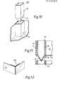
- Figure 12 illustrates an alternative form of strut 40a, which is not of open hollow section but nevertheless acts as a load-bearing member to support containers above it in a stack.
- the strut 40a may be formed by making up the blanks as hereinbefore described to form hollow corner struts which are then inverted by pushing their corners nearest the centre of the container outwardly to lie against the corner of the container.
- the foot portion of the strut is not arranged to reach to the base of the container so that this inversion step is made possible and so that the box may still be flattened by pressing the side walls to lie against the base.
- part of the side walls 12 and/or 14 may be cut away so that the height of the walls, for most of their length between the struts 40, is dropped to about four fifths of the height of the struts 40.
- Such an arrangement is particularly applicable when the stacked containers do not have lids, e.g. when the containers have locating means which obviate the need for lids.
- the material of the blank, and of the container from which it is made can be cardboard, plastics or any other suitable material which is foldable.
- a suitable material is so-called "polycoated” cardboard, a plastics coated cardboard which resists softening or disintegration in moist conditions. It is common practice to hydrocool fruit and vegetables, e.g. lettuce or tomatoes, which have been picked at optimum ripeness, and then to pack the hydrocooled food produce into polycoated cardboard containers, which are then stacked and placed in cold storage for up to three days. It is important that the containers maintain their strength and rigidity during this period and under these damp conditions.
Abstract
A blank of foldable sheet material, for erection into a container, comprises a generally rectangular contral portion (10) for forming the base of the container and panels (12, 14) hingedly connected along at least three edges of the central portion for erection to form side walls of the container, at least one of the panels being provided with a flap (20) extending from and hinged (22) to an end thereof, the flap having at least one fold line (26) which extends substantially parallel to the hinge (22), whereby the flap (20) may be folded to form a load-bearing corner strut (40) which can be located within the base (10) of the container, when the container is erected. The invention also contemplates a container made from a blank of foldable sheet material comprising a base (10) and at least three side walls (12, 14) upstanding from the base and extending along corresponding edges of the base, and at least one load-bearing corner strut (40) formed integrally from the blank and disposed at an angle enclosed between two of the side walls.
Description
- The present invention relates to a blank of foldable sheet material for erection into a container and to a container made from such a blank.
- A container must be suitable for maintaining the quality of the packaged goods. There is the additional requirement that best use is made of the available volume, because of increasingly high transport costs. Accordingly, boxes for packing fragile goods, for instance, food produce such as tomatoes or mushrooms, should be as large as possible yet not so large that the lowermost layers of the commodity are crushed by those above. This is particularly important for high quality, grade A food produce, such as tomatoes or mushrooms.
- For optimum use of the available space when transporting such food produce, it is desirable for the containers, individually limited in their volume, to be stackable one above the other, the lower containers in the stack being able to bear the load of packed containers above. The number of containers which can be stacked in this way is determined by the strength of the lowermost box in the stack. For conventional cardboard boxes which package tomatoes, the stack will be approximately twelve boxes high. In addition to the weight of the packed boxes above it, the lowermost box must be strong enough to withstand the vibrations of the vehicle on which the stack of containers is transported.
- One way in which known types of cartons are strengthened against vertical loads is to have thickened side walls, or even to have side walls of double thickness material from which they are made, such as cardboard or plastics material. This involves uneconomic use of the material from which the container is made.
- Another known approach for making a container which is easily stacked is to provide a peripheral stacking flange at the upper edges of the side wäJls. However, this also involves the case of extra material, and has the additional disadvantage of making packing of the containers rather more difficult, because the flange obstructs access to the interior of the box. Such a container also cannot be collapsible and erectable.
- It is also desirable for containers for packaging tomatoes and the like to be erectable from a flattened, collapsed state. Known containers suffer from the problem that if the boxes are strong enough to stack then they will be of rigid construction and not able to be erected from a flattened, collapsed state. This is a disadvantage since the empty boxes, sent to food produce packers, will take up an excessive amount of space. It is clearly desirable for the empty boxes to be delivered in a collapsed, substantially flat state from which the box may readily be erected for filling with the food produced. Moreover, a collapsible box, once opened to receive food produce, clearly must not return readily to its collapsed state when it is stacked, if the packed food produce is not to be crushed.
- It is an object of the present invention to overcome the problems of stackability, with economic use of material from which the container, such as a box, is to be made, as well as providing a container which may preferably be collapsed, yet is readily opened up to receive goods without being returned to its collapsed state simply by stacking another container on top.
- According to a first aspect of the invention there is provided a blank of foldable sheet material, intended for erection into a container, comprising a central, substantially rectangular portion for forming the base of the container, and panels hingedly connected by first fold lines extending along the edges of at least three sides of said central portion for erection to form side walls of the container, at least one of said panels being provided with a flap extending from and hinged to an end thereof, said flap being provided with at least one second fold line extending substantially parallel to said hinge, whereby the flap may be folded to form a load-bearing corner strut which can be located within the base of the container when the container is erected.
- Preferably, the blank is made from a single sheet of material, the said central portion, the panels and said at least one flap being integral, the hinge between the or each flap and its respective panel comprising a fold line in the sheet of material. Being integral, the blank lends itself to simple and therefore economic assembly into a container.
- Suitably, the hinge between said at least one flap and the panel to which it is connected extends approximately perpendicular to the first fold line of the respective panel, and the flap has a series of spaced second fold lines extending substantially parallel to the hinge and dividing the flap into a plurality of sections, whereby, on folding said flap about the hinge and the second fold lines, the load-bearing strut is formed.
- Preferably, the or each strut is collapsible in shear, by folding it about the hinge and/or the second fold lines to flatten the sections against each other. As a result of this strut itself being collapsible, the blank may be erected to form a container which can be flattened or opened.
- Suitably, at least one of the sections forming the flap extends substantially to the imaginary projection of the first fold line to form a foot portion, whereby, on folding the flap about the hinge and the second fold lines to form the strut, a strut of hollow section is formed, the flap sections forming walls of the hollow strut, and the foot portion being able to abut.-. the base of the container when the respective panel is folded about the first fold line to form a side wall of the container. As a result, the load borne by the or each strut when the container is supporting another such container in a stack can be transmitted to and therefore spread throughout the base of the container.
- Such a flap may, for instance, be divided by the said second fold lines into four sections, whereby the flap can be folded into a strut of quadrilateral hollow section.
- So that the strut can be collapsed and hence the container flattened without the material either side of the first fold lines being creased and therefore damaged by the foot portion of the strut, a slit is preferably provided in the first fold line hingedly connecting the or each panel having a flap to the base, said slit being openable to receive therethrough the foot portion of the strut when the side wall formed by that panel is folded inwardly to lie against the base of the container.
- For ease of construction of the container from the blank, the panel adjacent that panel having the flap is preferably adapted to be connected to one of the flap sections when the container is erected.
- So that the container is erectable from a flat to an open state, even when the side walls are interconnected, the panel adjacent the panel having the flap is preferably provided, at that end adjacent the flap, with the fold line angled with respect to its first fold line to delineate a foldable corner portion of the panel, whereby, when interconnected, the side walls formed by the said two panels are foldable generally inwardly about their first fold lines to lie against the base of the container, thus flattening it, with said corner portion being folded outwardly.
- In a preferred embodiment of blank which may be readily erected to form a container, a panel is provided on each of the four sides of the central portion, the panels of one pair of opposite panels being provided with a flap hingedly connected at each of their ends, the other pair of panels having no flaps.
- Suitably, the flap extends in a direction perpendicular to its fold lines beyond the overall width of that adjacent panel to which it is not connected. This facilitates the operation carried out by mechanical handling apparatus in an assembly line making up containers from such blanks, where the apparatus has to pick up the flap in preference to the panel and fold that flap about the hinge and second fold lines to form a strut.
- For making a container having side walls substantially vertically upstanding from the base, the hinge of each flap extends substantially perpendicular to the respective first fold line.
- Alternatively, the hinge of each flap extends at an obtuse angle to the respective first fold line, whereby, on folding said panels about their first fold lines to form the side walls and connecting adjacent side walls to one another, a container having outwardly flared side walls is formed.
- For forming containers which can positively locate the base of a container stacked on top, at least some of the sections of the or each flap extend, in a direction parallel to said second fold lines, outwardly from said central portion, less far than the maximum extent of the adjacent portion of the panel to which it is hingedly connected, whereby, on folding the or each flap about its hinge and second fold lines, a strut which is shorter than the adjacent portion of the side wall is formed.
- According to a second aspect of the invention, there is provided a container made from a blank of foldable sheet material, comprising a base and at least three side walls upstanding from the base and extending along corresponding edges of the base, and at least one load-bearing corner strut formed integrally from the blank and disposed at an angle enclosed between two of said side walls.
- Preferably, said at least one strut is collapsible between a position in which it lies substantially flat against the base and a position in which it is upstanding from the base, whereby the container is erectable from a collapsed, substantially flat state into an open state, in which open state the container may be stacked on like containers, the container being supported by the corner strut or struts of the container below it in the stack.
- Suitably, the or each corner strut is of open hollow section.
- Advantageously, the side walls are hingedly connected to the edges of the base and to an adjacent side wall, a slit being provided in each hinge connection adjacent each corner strut, to receive therethrough a lower end portion of the strut when it is in its position lying against the base. The slit allows the lower end portion of the strut to pass through it, instead of pressing into the hinge between the side wall and the base thus crumpling the material either side of the hinge.
- The container side walls may be substantially vertically upstanding from the base or may be at an obtuse angle thereto to form a container having outwardly flaring side walls. This latter form is useful where enhanced ventilation of the packaged goods, e.g. mushrooms, in the stacked containers is desirable.
- In this embodiment, the corner struts are preferably shorter than the height of the adjacent portions of the side walls, whereby the containers may be positively located one above another, by being disposed to sit partially within one another, the base of one container being retained within the corners of the container below. Furthermore, there is the advantage that there is no need to provide lids for these stacked containers, the base of one container acting as the lid for the container below; only the topmost container requires a lid.
- In another advantageous embodiment, the container further comprises a post for the or each hollow corner strut, each post having an outer cross-sectional dimension substantially equal to the inner cross-sectional dimension of the hollow strut, whereby the post can be received within the corresponding hollow corner strut with friction fit.
- The posts are inserted into corresponding hollow corner struts and may provide some additional rigidity for the strut.
- Preferably, the posts are longer than the height of the corner struts and a hole is provided in the base below each corner strut, so that the posts received within the corner strut extend through the base of the container, whereby the posts of adjacent containers in a stack of containers can rest on one another when the containers are stacked on one another. Thus, when the posts have been inserted into the corner struts, the lower ends of the posts project through the base of the container to rest on the posts of the container below in the stack.
- In this embodiment, the posts preferably have interengagement means at their ends, whereby the posts can fit together end to end. In this way, the containers interengage one another when the containers are stacked, thereby forming a stable stack in which no container lids are required, apart from the topmost container in the stack.
- The posts may be inserted into the struts either from above or from below. When they are inserted from below a flange may be provided on the post, against which flange the base of the container abuts.
- Embodiments of the invention will now be described, by way of example only and with reference to the accompanying drawings, in which:
- Figure 1 is a plan view of a blank in accordance with a first embodiment of the invention;
- Figure 2 illustrates consecutive steps in the method of erecting a container from the blank of Figure 1;
- Figure 3 is a perspective view of a container erected from the blank of Figures 1 and 2;
- Figure 4 is a plan view of a blank in accordance with a second embodiment of the invention;
- Figure 5 is a perspective view of a container erected from the blank of Figure 4;
- Figure 6 is a plan view of a blank in accordance with a third embodiment of the invention;
- Figure 7 is a perspective view of a container having outwardly flared side walls erected from the blank of Figure 6;
- Figure 8 is a partial view, on an enlarged scale, of a flap forming part of a blank in accordance with a fourth embodiment of the invention;
- Figure 9 is a partial perspective view showing one corner of the container erected from a blank according to Figure 8, showing a corner strut which is shorter than the adjacent portions of the side walls;
- Figure 10 is a partial perspective view showing one corner of a container with a post for insertion into the corner strut;
- Figure 11 is a vertical cross-section through a corner region of a container having a post inserted into the corner strut disposed above and spaced from a similar container onto which it is to be stacked; and
- Figure 12 shows a partial perspective view of a corner region of a further embodiment of container, showing an alternative type of corner strut.
- Figures 1 and 2 illustrate a blank and Figure 3 a container respectively in accordance with one embodiment of the invention. The blank of Figures 1 and 2 generally comprise a
central portion 10 and panels connected around all four edges of the central portion. The panels are arranged inopposite pairs first fold lines panels 14 of only one pair of panels, is aflap 20, hingedly connected to the panel 15 by ahinge 22. - Each of the four
flaps 20 is divided into four section 241, 242, 243 and 244 by a series of substantially parallel second fold lines 26. - Each of the two
panels 12 which does not haveflaps 20 extending therefrom is provided with a pair offold lines 28 disposed at an angle to the fold lines 16 along which thepanel 12 is hinged to the central portion of the blank. These fold lines delineatecorner portion 29 of thepanels 12. - L-shaped slits 30 are cut in the blank, at least one limb of the slit lying along the
first fold line 18 along which thepanels 14 are hinged to thecentral portion 10. There is provided a slit 30 for eachrespective flap 20. Thus, in this embodiment, there are four slits 30. - Preferably the blank is made from a single sheet of material, the blank being cut according to the outer perimeter as shown in Figure 1, the slits 30 being cut simultaneously or subsequently to cutting the outline of the blank. Similarly,
apertures 32 are cut into thepanels first fold lines second fold line 26 in thepanels 20 and the fold lines 28 in thepanels 12 are then creased into the blank, either by pressing or rolling. - The container shown in Figure 3 may be made from the blank shown in Figures 1 and 2 in the following way. The blank is passed longitudinally along an assembly line in the direction of arrow A (Figure 1). Firstly, each of the four
flaps 20 is folded in half about its central second fold line 26' in the direction of arrow B so that the two outermost sections of each flap 241 and 242 overlie the two innermost sections 244 and 243 respectively. A flap folded in this way is shown at the left top hand corner of Figure 2. The underside of section 241, which is now uppermost then has adhesive applied thereto by rollers or other known means. - The next step is to fold the
flaps 20 again, this time about theirhinge 22 in the direction of arrow C (Figure 2) into the position shown in the lower left hand corner of Figure 2, the flap then lying against thepanel 14 and section 24, previously coated with adhesive, adheres topanel 14. Section 244 of each flap then has adhesive applied thereto. - Although Figure 2 shows flaps at different positions, it is to be understood that on the assembly line the left hand pair of flaps, as viewed in Figures 1 and 2 are first manipulated by the mechanical handling apparatus to fold them in half and then simultaneously folded once more about their
hinges 22, the blank then advancing along the line until the mechanical handling apparatus performs the same two consecutive operations on both of their right hand flaps, as viewed in Figures 1 and 2. Theflaps 20 extend beyond the full width ofpanels 12, so that it is easier for the mechanical handling apparatus to pick and fold theflaps 20 in preference to thepanels 12. - At the next stage, the
panels 12 which are now free of theflaps 20 are folded about theirfirst fold lines 16 to lie against thecentral portion 10 of the blank and one of thepanels 12 folded in this way is shown at the bottom of Figure 2. In practice, of course, both these panels will be folded about theirfold lines 16 simultaneously. Thecorner portions 29 of thepanels 12 are then folded back, as shown in Figure 2 and, again, all four corner portions are folded back simultaneously. - The blank is then turned through 90° for the mechanical handling apparatus to grasp the
panels 14 and fold them about the fold lines 18 so that thesections 244, coated with adhesive, are brought into contact with thecorner portions 29 ofpanels 12. If contact adhesive is used throughout, there is no need for pressure to be applied to adhere section 241 topanel 14 and section 244 to thecorner portion 29 ofpanel 12. - A container in a flat, or collapsed state has now been formed and all that is required is for the
panels central portion 10 to form the open container shown in Figure 3. Thepanels central portion 10 which acts as the base of the container. Each of theflaps 20 forms an open,hollow section strut 40 which abuts thebase 10 and acts as a load-bearing member so that the container is capable of bearing considerable loads. Thestruts 40 thus enable the container to be stacked. - Each of the flaps extend as far as an imaginary extension of the
fold line 18 hingedly connecting itsrespective panel 14 to the central portion to form afoot portion 34. It is necessary for the flap to extend this far in this direction so that, when folded to form thestrut 40, the strut will be able to abut thebase 10 of the container thereby transmitting load carried by the strut to the base of the container. It thus ensures that the container once opened up into the state shown in Figure 3 will not collapse to crush produce packaged within the container, as well as spreading load through the base. - The purpose of slots 30 in the fold lines 18 is to receive the foot portions of the strut when the box is in its collapsed, flat state so that the
foot portions 34 do not press into the fold lines 18, thus damaging the material either side of those fold lines. The strength and neat appearance cfthe container is thus maintained. - The
apertures 32 in theside walls - Figures 4 and 5 relate to a second embodiment of the invention, illustrating a blank and a container made from such a blank respectively. The blank shown in Figure 4 is much the same as that shown in Figure 1, with the exception that the
flaps 20 are provided as extensions hingedly connected to thelonger panels 12, rather than to theshorter panels 14.Panels 14 are instead provided with thefold line 28, which enable the container to be collapsed. - Figures 6 and 7 relate to a third embodiment of the invention and illustrate how a container having outwardly flared side walls can be formed. Such a container is particularly useful where enhanced ventilation of a packaged commodity, such as mushrooms, is required, when the containers are stacked one on top of each other. The hinges 22 are angled with respect to the
first fold lines 18 and theintersection 36 cut between theflaps 20 andadjacent panels 12 is angled with respect to thefirst fold line 16, whereby theside walls - Figures 8 and 9 relate to a further form, in which the blank is so shaped to give, in the erected container, a height difference between the
struts 40 and those portions of theside walls base 10 of a container which is stacked above, and rests on thestruts 40 of that container. In the illustrated embodiment, sections 242 and 243 are made shorter than adjacent sections 241 and 244 of theflap 20, whereby a recessedstrut 40, which is less high than the depth of those portions of theside walls struts 40. A stack of such containers is particularly stable and has an added advantage that individual lids for the containers are not necessary, as thebase 10 of one container acts as the lid for the container below it. Only the top container in the stack needs a lid. - Stacking of the containers having locating means, such as are illustrated in Figures 8 and 9, is facilitated if the containers have
side walls base 10 of a container between the flaredside walls - Clearly, other forms of means for locating the base of a container stacked above are possible. For instance, section 241 of the
flap 20 may be co-extensive withsections 242 and 243, as it does not have to be flush with the top edge of theside wall 12 in the erected container. However, section 242 should, in all cases, be co-extensive with therespective section 243, so that both sections reach to the same height above thebase 10 of the erected container in order that they can both bear the load of the container stacked above. - Instead of shaping the
flaps 20 so they form struts 40 which are recessed below the adjacent portions of theside walls struts 40, to form the locating means. Alternatively, a combination is possible in which sections 244 of theflaps 20 extend, at their edges which are uppermost in the erect container, above the sections 243 and 242 with that portion of theside wall flap 20 is hinged also being raised in height, compared with the rest of the side walls. - Figures 10 and 11 relate to two further embodiments of a container which is adapted to be positively located on a similar container below it in a stack, to form a stable stack of partially nested containers. For the container of Figure 10, posts 42 are received one in each of the corner struts 40. The corner posts 42 are preferably hollow and may be made of injected moulded plastics material. The outer cross-section of the
post 42 corresponds with the internal transverse cross-sectional dimensions of thecorner strut 40 in which it is received so that the post may be held within the strut by a friction fit. Each of theposts 42 has anintegral projection 44 which extends, when thepost 42 is received within thestrut 40, through an aperture in the base located beneath thestrut 40. Theprojection 44 will extend into the open upper end of thehollow post 42 belonging to the container below in the stack, and this is better illustrated by Figure 11. - Figure 11 shows an alternative type of
post 46 for insertion into the corner posts 40, and is provided with aflange 48. Thispost 46 is inserted into thestrut 40 from below until theflange 48 abuts thebase 10 of the container. Again, thepost 46 is of complimentary cross-section to that of the corner strut and is held therein by friction fit. Thecontainers having posts 46 inserted into each of their corner struts can then be nested one on top of each other in a stack. - Figure 12 illustrates an alternative form of
strut 40a, which is not of open hollow section but nevertheless acts as a load-bearing member to support containers above it in a stack. Thestrut 40a may be formed by making up the blanks as hereinbefore described to form hollow corner struts which are then inverted by pushing their corners nearest the centre of the container outwardly to lie against the corner of the container. In this embodiment, the foot portion of the strut is not arranged to reach to the base of the container so that this inversion step is made possible and so that the box may still be flattened by pressing the side walls to lie against the base. - It is desirable, for certain food produce, to have good ventilation of the containers. In addition to, or instead of, the ventilation means already described, part of the
side walls 12 and/or 14 may be cut away so that the height of the walls, for most of their length between thestruts 40, is dropped to about four fifths of the height of thestruts 40. Such an arrangement is particularly applicable when the stacked containers do not have lids, e.g. when the containers have locating means which obviate the need for lids. - The material of the blank, and of the container from which it is made can be cardboard, plastics or any other suitable material which is foldable. Where the containers are to hold food produce in cold storage, a suitable material is so-called "polycoated" cardboard, a plastics coated cardboard which resists softening or disintegration in moist conditions. It is common practice to hydrocool fruit and vegetables, e.g. lettuce or tomatoes, which have been picked at optimum ripeness, and then to pack the hydrocooled food produce into polycoated cardboard containers, which are then stacked and placed in cold storage for up to three days. It is important that the containers maintain their strength and rigidity during this period and under these damp conditions.
Claims (25)
1. A blank for foldable sheet material, intended for erection into a container, comprising a central, substantially rectangular portion (10) for forming the base of the container, and panels (12, 14) hingedly connected by first fold lines (16, 18) extending along the edges of at least three sides of said central portion for erection to form side walls of the container, at least one of said panels (12, 14) being provided with a flap (20) extending from and hinged to an end thereof, said flap being provided with at least one second fold line (26) extending substantially parallel to said hinge (22), whereby the flap (20) may be folded to form a load-bearing corner strut (40) which can be located within the base (10) of the container when the container is erected.
2. A blank as claimed in Claim 1, made from a single sheet of material, the said central portion (10), the panels (12, 14) and said at least one flap (20) being integral, the hinge (22) between the or each flap and its respective panel comprising a fold line in the sheet of material.
3. A blank as claimed in Claim 1 or Claim 2, wherein said hinge (22) of said flap extends approximately perpendicular to the first fold line (16, 18) of the respective panel (12, 14) and the flap (20) has a series of spaced second fold lines (26) extending substantially parallel to the hinge (22) and dividing the flap (20) into a plurality of sections (24), whereby, on folding said flap (20) about the hinge (22) and the second fold lines (24), the load-bearing strut (40) is formed.
4. A blank as claimed in Claim 3, wherein the or each strut (40) is collapsible in shear, by folding it about the hinge (22) and/or the second fold lines (26) to flatten the sections (24) against each other.
5. A blank as claimed in Claim 4, wherein at least one of the sections (242, 243) forming the flap (20) extends substantially to the imaginary projection of the first fold line to form a foot portion, whereby, on folding the flap (20) about the hinge (22) and the second fold lines (26) to form the strut (40), a strut of hollow section is formed, the flap sections (24) forming walls of the hollow strut, and the foot portion being able to abut the base (10) of the container when the respective panel (12, 14) is folded about the first fold line (16, 18) to form a side wall of the container.
6. A blank as claimed in Claim 5, wherein the flap (20) is divided by the said second fold lines (26) into four sections (24), whereby the flap can be folded into a strut of quadrilateral hollow section.
7. A blank as claimed in Claim 5 or Claim 6, in which a slit (30) is provided in the first fold line (16, 18) hingedly connecting the or each panel (12, 14) having a flap to the base (10), said slit being openable to receive therethrough the foot portion of the strut (40) when the side wall formed by that panel is folded inwardly to lie against the base of the container.
8. A blank as claimed in any of Claims 3 to 7, in which the panel (12, 14; 14, 12) adjacent that panel (14, 12; 12 14) having the flap (20) is adapted to be connected to one of the flap sections (244) when the container is erected.
9. A blank as claimed in Claim 8, wherein said panel adjacent the panel having the flap is provided, at that end adjacent the flap, with a fold line angled with respect to its first fold line (28) to delineate a foldable corner portion (29) of the panel, whereby, when interconnected, the side walls formed by the said two panels are foldable generally inwardly about their first fold lines (16, 18) to lie against the base (10) of the container, thus flattening it, with said corner portion (29) being folded outwardly.
10. A blank as claimed in any preceding claim, in which a panel (12, 14) is provided on each of the four sides of the central portion, the panels of one pair (12 or 14) of opposite panels being provided with a flap hingedly connected at each of their ends, the other pair of panels having no flaps.
11. A blank as claimed in any of Claims 3 to 10, wherein the flap (20) extends in a direction perpendicular to its second fold lines (26) beyond the overall width of the adjacent panel to which it is not connected.
12. A blank as claimed in any of Claims 3 to 11, in which the hinge (22) of each flap (20) extends substantially perpendicular to the respective first fold line (16, 18), whereby, on folding said panels about their first fold lines to form the side walls of the container and connecting adjacent side walls to one another, a container having side walls substantially perpendicular to the base is formed.
13. A blank as claimed in any of Claims 3 to 11, in which the hinge (22) of each flap (20) extends at an obtuse angle to the respective first fold line (16, 18), whereby, on folding said panels about their first fold lines to form the side walls of the container and connecting adjacent side walls to one another, a container having outwardly flared side walls is formed.
14. A blank as claimed in any of Claims 3 to 13, wherein at least some of the sections (242, 2.43) of the or each flap extend, in a direction parallel to said second fold lines, outwardly from said central portion, less far than the maximum extent of the adjacent portion of the panel to which it is hingedly connected, whereby, on folding the or each flap about its hinge (22) and second fold lines 26, a strut (40) which is shorter than the adjacent portion of the side wall is formed.
15. A container erected from a blank as claimed in any of the preceding claims.
16. A container made from a blank of foldable sheet material, comprising a base (10) and at least three side walls (12, 14) upstanding from the base and extending along corresponding edges of the base, and at least one load-bearing corner strut (40) formed integrally from the blank and disposed at an angle enclosed between two of said side walls.
17. A container as claimed in Claim 16, wherein said at least one strut (40) is collapsible between a position in which it lies substantially flat against the base (10) and a position in which it is upstanding from the base, whereby the container is erectable from a collapsed, substantially flat state into an open state, in which open state the container may be stacked on like containers, the container being supported by the corner strut or struts (40) of the container below it in the stack.
18. A container as claimed in Claim 16 or Claim 17, in which the or each strut (40) is of open hollow section.
19. A container as claimed in any of Claims 16 to 18, in which the side walls (12, 14) are hingedly connected to the edges of the base (10) and to an adjacent side wall, a slit (30) being provided in each hinge connection (16,18) adjacent each corner strut, to receive therethrough a lower end portion of the strut (40) when it is in its position lying against the base (10).
20. A container as claimed in any of Claims 16 to 19, in which the side walls (12, 14), when upstanding from the base (10) of the container, are at an obtuse angle thereto so that the side walls flare outwardly from the base.
21. A container as claimed in Claim 20, in which the corner struts (40) are shorter than the height of the portions of the side walls adjacent the struts, whereby the container may positively locate on its struts the base of a container stacked above it.
22. A container as claimed in any of Claims 18 to 21, further comprising a post (42; 46) for the or each hollow corner strut {40), each post having an outer cross-sectional dimension substantially equal to the inner cross-sectional dimension of the hollow strut, whereby the post can be received within the corresponding hollow corner strut with friction fit.
23. A container as claimed in Claim 22, in which the posts (42; 46) are longer than the height of the corner struts (40) and wherein a hole is provided in the base (10) of the container below each corner strut, so that the posts received within the corner strut extend through the base of the container, whereby the posts of adjacent containers in a stack of containers can rest on one another when the containers are stacked on one another.
24. A container as claimed in Claim 23, wherein the posts (42; 46) have interengagement means (44) at their ends, whereby the posts can fit together end to end, to positively locate containers stacked one above another.
25. A container as claimed in Claim 24, in which each post is provided with a flange (48) against which the base (10) of the container abuts.
Applications Claiming Priority (2)
| Application Number | Priority Date | Filing Date | Title |
|---|---|---|---|
| GB8125624 | 1981-08-21 | ||
| GB8125624 | 1981-08-21 |
Publications (1)
| Publication Number | Publication Date |
|---|---|
| EP0076883A1 true EP0076883A1 (en) | 1983-04-20 |
Family
ID=10524108
Family Applications (1)
| Application Number | Title | Priority Date | Filing Date |
|---|---|---|---|
| EP81305876A Withdrawn EP0076883A1 (en) | 1981-08-21 | 1981-12-14 | Blank for a tray |
Country Status (1)
| Country | Link |
|---|---|
| EP (1) | EP0076883A1 (en) |
Cited By (19)
| Publication number | Priority date | Publication date | Assignee | Title |
|---|---|---|---|---|
| GB2148254A (en) * | 1983-10-27 | 1985-05-30 | Corrugated Prod Ltd | Collapsible boxes |
| GB2157659A (en) * | 1984-03-21 | 1985-10-30 | Omegalodge Ltd | Boxes and blanks therefor |
| WO1986005159A1 (en) * | 1985-02-27 | 1986-09-12 | Johnsen, Harald | Crate |
| GB2196608A (en) * | 1986-10-01 | 1988-05-05 | Reed Packaging Ltd | Collapsible tray |
| FR2613699A1 (en) * | 1987-04-13 | 1988-10-14 | Balzani Jean | Package for fruit and vegetables |
| EP0394544A1 (en) * | 1989-04-27 | 1990-10-31 | GÜNTER HOFFMANN GMBH & CO. KG KARTONAGENFABRIK | Crate for the packaging of fruit or vegetables |
| EP0445442A1 (en) * | 1990-03-09 | 1991-09-11 | Knp Free B.V. | Tray and blank therefor |
| GR910100463A (en) * | 1991-11-20 | 1993-07-30 | Ilias Tsamourgkelis | Practical resistant packing - case |
| US5261594A (en) * | 1992-01-03 | 1993-11-16 | Brown James M | Container post for product protection |
| US5285956A (en) * | 1993-03-31 | 1994-02-15 | Weyerhaeuser Company | Container post for product protection |
| US5415345A (en) * | 1990-09-15 | 1995-05-16 | Fra.Mo. Snc Di Franca Riva & C | Box with integral corner reinforcements |
| ES2070675A2 (en) * | 1992-07-21 | 1995-06-01 | Videcart Sa | Preformed plate for obtaining trays for transporting products |
| US5431335A (en) * | 1993-03-05 | 1995-07-11 | Iberoamericana Del Embalaje S.A. | Light-weight container |
| EP0731032A1 (en) * | 1995-03-07 | 1996-09-11 | Gsf Verpakkingen B.V. | Box and blank for a box |
| WO1998000343A1 (en) * | 1996-06-28 | 1998-01-08 | Gsf Verpakkingen B.V. | Box and blank for a box |
| WO1999017995A1 (en) * | 1997-10-07 | 1999-04-15 | Videcart, S.A. | Tray for transporting products, and method for its fabrication |
| US20110226846A1 (en) * | 2009-01-14 | 2011-09-22 | Mitsubishi Electric Corporation | Packing box and manufacturing method thereof |
| WO2015136741A1 (en) * | 2014-03-14 | 2015-09-17 | レンゴー株式会社 | Packing box and box manufacturing apparatus |
| WO2021072454A1 (en) * | 2019-10-10 | 2021-04-15 | Marthinus Jordaan Nortje | Lightweight casket; structural strength, waterproof and foldable |
Citations (5)
| Publication number | Priority date | Publication date | Assignee | Title |
|---|---|---|---|---|
| US3029010A (en) * | 1957-08-30 | 1962-04-10 | William P Frankenstein | Cartons |
| DE2450702A1 (en) * | 1973-10-30 | 1975-05-07 | Hendrikus Petrus Verboord | BOX |
| DE2728444A1 (en) * | 1977-06-24 | 1979-01-04 | Osthushenrich Kg | Stackable collapsible box - has stacking corners with inclined supporting walls higher than box sidewalls |
| DE2905819A1 (en) * | 1978-02-17 | 1979-08-23 | Ludwig Hartelmueller | STACKABLE TRANSPORT CONTAINER |
| DE2816563A1 (en) * | 1978-04-17 | 1979-10-25 | Ver Verpackungs Gmbh | Packing carton made from single sheet - has corner members folded into straight prismatic shape at wall ends |
-
1981
- 1981-12-14 EP EP81305876A patent/EP0076883A1/en not_active Withdrawn
Patent Citations (5)
| Publication number | Priority date | Publication date | Assignee | Title |
|---|---|---|---|---|
| US3029010A (en) * | 1957-08-30 | 1962-04-10 | William P Frankenstein | Cartons |
| DE2450702A1 (en) * | 1973-10-30 | 1975-05-07 | Hendrikus Petrus Verboord | BOX |
| DE2728444A1 (en) * | 1977-06-24 | 1979-01-04 | Osthushenrich Kg | Stackable collapsible box - has stacking corners with inclined supporting walls higher than box sidewalls |
| DE2905819A1 (en) * | 1978-02-17 | 1979-08-23 | Ludwig Hartelmueller | STACKABLE TRANSPORT CONTAINER |
| DE2816563A1 (en) * | 1978-04-17 | 1979-10-25 | Ver Verpackungs Gmbh | Packing carton made from single sheet - has corner members folded into straight prismatic shape at wall ends |
Cited By (26)
| Publication number | Priority date | Publication date | Assignee | Title |
|---|---|---|---|---|
| GB2148254A (en) * | 1983-10-27 | 1985-05-30 | Corrugated Prod Ltd | Collapsible boxes |
| GB2157659A (en) * | 1984-03-21 | 1985-10-30 | Omegalodge Ltd | Boxes and blanks therefor |
| WO1986005159A1 (en) * | 1985-02-27 | 1986-09-12 | Johnsen, Harald | Crate |
| GB2196608A (en) * | 1986-10-01 | 1988-05-05 | Reed Packaging Ltd | Collapsible tray |
| FR2613699A1 (en) * | 1987-04-13 | 1988-10-14 | Balzani Jean | Package for fruit and vegetables |
| EP0394544A1 (en) * | 1989-04-27 | 1990-10-31 | GÜNTER HOFFMANN GMBH & CO. KG KARTONAGENFABRIK | Crate for the packaging of fruit or vegetables |
| EP0445442A1 (en) * | 1990-03-09 | 1991-09-11 | Knp Free B.V. | Tray and blank therefor |
| US5415345A (en) * | 1990-09-15 | 1995-05-16 | Fra.Mo. Snc Di Franca Riva & C | Box with integral corner reinforcements |
| GR910100463A (en) * | 1991-11-20 | 1993-07-30 | Ilias Tsamourgkelis | Practical resistant packing - case |
| US5261594A (en) * | 1992-01-03 | 1993-11-16 | Brown James M | Container post for product protection |
| ES2070675A2 (en) * | 1992-07-21 | 1995-06-01 | Videcart Sa | Preformed plate for obtaining trays for transporting products |
| US5431335A (en) * | 1993-03-05 | 1995-07-11 | Iberoamericana Del Embalaje S.A. | Light-weight container |
| US5285956A (en) * | 1993-03-31 | 1994-02-15 | Weyerhaeuser Company | Container post for product protection |
| EP0731032A1 (en) * | 1995-03-07 | 1996-09-11 | Gsf Verpakkingen B.V. | Box and blank for a box |
| WO1998000343A1 (en) * | 1996-06-28 | 1998-01-08 | Gsf Verpakkingen B.V. | Box and blank for a box |
| WO1999017995A1 (en) * | 1997-10-07 | 1999-04-15 | Videcart, S.A. | Tray for transporting products, and method for its fabrication |
| ES2134154A1 (en) * | 1997-10-07 | 1999-09-16 | Videcart Sa | Tray for transporting products, and method for its fabrication |
| US6378764B1 (en) * | 1997-10-07 | 2002-04-30 | Videcart, S.A. | Tray for transporting products, and method for its fabrication |
| US20110226846A1 (en) * | 2009-01-14 | 2011-09-22 | Mitsubishi Electric Corporation | Packing box and manufacturing method thereof |
| EP2377768A1 (en) * | 2009-01-14 | 2011-10-19 | Mitsubishi Electric Corporation | Packaging box and method of producing the same |
| EP2377768A4 (en) * | 2009-01-14 | 2013-01-02 | Mitsubishi Electric Corp | Packaging box and method of producing the same |
| US8628002B2 (en) | 2009-01-14 | 2014-01-14 | Mitsubishi Electronic Corporation | Packing box and manufacturing method thereof |
| WO2015136741A1 (en) * | 2014-03-14 | 2015-09-17 | レンゴー株式会社 | Packing box and box manufacturing apparatus |
| CN106132835A (en) * | 2014-03-14 | 2016-11-16 | 联合株式会社 | Packing crates and box forming apparatus |
| US9994355B2 (en) | 2014-03-14 | 2018-06-12 | Rengo Co., Ltd. | Packing box and box manufacturing apparatus |
| WO2021072454A1 (en) * | 2019-10-10 | 2021-04-15 | Marthinus Jordaan Nortje | Lightweight casket; structural strength, waterproof and foldable |
Similar Documents
| Publication | Publication Date | Title |
|---|---|---|
| EP0076883A1 (en) | Blank for a tray | |
| US6948617B2 (en) | Stackable container with support flanges | |
| US6508395B2 (en) | Stackable shipping container | |
| US5649663A (en) | Produce container improvement | |
| US6170740B1 (en) | Oval folding carton with automatic closing bottom | |
| US6296178B1 (en) | Container with triangular corner posts | |
| US7124890B2 (en) | Case ready stackable tray designs | |
| EP3184459B1 (en) | Shipping container convertible into a display configuration | |
| CA1307247C (en) | Carton and blank therefor | |
| US6808107B2 (en) | Economical, stackable container for retail goods | |
| US4913340A (en) | Tray for carrying food | |
| US6152359A (en) | Oval folding carton with automatic closing | |
| US5447269A (en) | Multiple unit box and blank therefor | |
| US5294043A (en) | Product carton | |
| US5415345A (en) | Box with integral corner reinforcements | |
| EP0579479A1 (en) | Fruit and vegetable box | |
| US3829001A (en) | Compartmented box | |
| US20060138206A1 (en) | Stackable container and container blank (L corner) | |
| GB2205083A (en) | Boxes formed from blanks | |
| US3783579A (en) | Method of packaging containers in a carton blank | |
| US20060138204A1 (en) | Stackable container with angled corner panel and container blank | |
| US20060138205A1 (en) | Stackable container with air cell corner assembly and associated container blank | |
| GB2266705A (en) | Stacking tray | |
| EP0863081B1 (en) | Distribution of fresh packed products | |
| US20240017873A1 (en) | Hinged-Lid Box |
Legal Events
| Date | Code | Title | Description |
|---|---|---|---|
| PUAI | Public reference made under article 153(3) epc to a published international application that has entered the european phase |
Free format text: ORIGINAL CODE: 0009012 |
|
| AK | Designated contracting states |
Designated state(s): AT BE CH DE FR GB IT LI LU NL SE |
|
| STAA | Information on the status of an ep patent application or granted ep patent |
Free format text: STATUS: THE APPLICATION IS DEEMED TO BE WITHDRAWN |
|
| 18D | Application deemed to be withdrawn |
Effective date: 19831221 |
|
| RIN1 | Information on inventor provided before grant (corrected) |
Inventor name: CRISP, MICHAEL WILLOUGHBY |