EP0074021A1 - X-ray examination apparatus - Google Patents
X-ray examination apparatus Download PDFInfo
- Publication number
- EP0074021A1 EP0074021A1 EP82107827A EP82107827A EP0074021A1 EP 0074021 A1 EP0074021 A1 EP 0074021A1 EP 82107827 A EP82107827 A EP 82107827A EP 82107827 A EP82107827 A EP 82107827A EP 0074021 A1 EP0074021 A1 EP 0074021A1
- Authority
- EP
- European Patent Office
- Prior art keywords
- hollow cylinder
- ray examination
- ray
- support plate
- patient support
- Prior art date
- Legal status (The legal status is an assumption and is not a legal conclusion. Google has not performed a legal analysis and makes no representation as to the accuracy of the status listed.)
- Granted
Links
Images
Classifications
-
- A—HUMAN NECESSITIES
- A61—MEDICAL OR VETERINARY SCIENCE; HYGIENE
- A61B—DIAGNOSIS; SURGERY; IDENTIFICATION
- A61B6/00—Apparatus for radiation diagnosis, e.g. combined with radiation therapy equipment
- A61B6/06—Diaphragms
-
- G—PHYSICS
- G21—NUCLEAR PHYSICS; NUCLEAR ENGINEERING
- G21K—TECHNIQUES FOR HANDLING PARTICLES OR IONISING RADIATION NOT OTHERWISE PROVIDED FOR; IRRADIATION DEVICES; GAMMA RAY OR X-RAY MICROSCOPES
- G21K1/00—Arrangements for handling particles or ionising radiation, e.g. focusing or moderating
- G21K1/02—Arrangements for handling particles or ionising radiation, e.g. focusing or moderating using diaphragms, collimators
- G21K1/04—Arrangements for handling particles or ionising radiation, e.g. focusing or moderating using diaphragms, collimators using variable diaphragms, shutters, choppers
Definitions
- the invention relates to an x-ray examination device with a patient support plate, with an x-ray tube arranged on one side of the patient support plate, with a primary beam blanking device producing a narrowly hidden x-ray beam that can be pivoted in a fan-shaped plane, and with a detector arrangement arranged on the other side of the patient support plate and exposed to the beam .
- An X-ray examination device has already become known in which the beam cone emerging from an X-ray tube is fanned in by a slit diaphragm and in which a radially slotted circular diaphragm disk made of radiopaque material is rotatably mounted in a plane perpendicular to the beam direction behind the slit diaphragm in the beam direction.
- the beam which is masked out in this way and is pencil-strong, moves from one side to the other when the aperture disk is rotated in the fan plane.
- a detector arrangement is assigned to this beam behind the examination object. When moving the X-ray examination device perpendicular to the fan plane, one slice of the examination object can be scanned after the other.
- the measured values of the individual detectors arranged in rows can be stored and temporarily displayed on a television viewing device in different shades of gray.
- the image corresponds to a conventional x-ray.
- the scattered radiation due to the relatively small volume penetrated by X-rays.
- the diaphragm disc must also have a significantly larger diameter than the width of the masked beam fan in the plane of the diaphragm disc. This leads to the fact that the entire blanking arrangement becomes so voluminous that it can only be used with under-table tube devices. But even there it shows that only part of the longitudinal stroke can be used when moving in the longitudinal direction of the table, because otherwise the slotted diaphragm disc would abut the front of the table frame.
- the object of the invention is to enlarge the examination area in the case of X-ray examination devices which scan the examination object in a line shape with a closely masked X-ray beam.
- a constructive solution is also to be found which makes it possible to work with such an x-ray examination apparatus by reversing the direction of the radiation with an upper table x-ray tube and a lower table receiving device.
- the masking device therefore contains, according to the invention, a hollow cylinder which is aligned with its axis of symmetry and approximately perpendicular to the beam direction and whose radiopaque wall bears two spiral slots offset by 180 from one another.
- a hollow cylinder allows the radiation to pass only in the area in which the two slits are located in the beam seen in the direction of the front and rear side of the lateral surface are in a line with the focus. This is always the case in only one point. This point moves in the axial direction when the hollow cylinder rotates.
- the blanked-out beam has a rhombic cross-section.
- this blanking device takes up little space perpendicular to the fan plane.
- the longitudinal stroke underneath the table frame is not hindered.
- this blanking device is also particularly suitable for X-ray examination devices in which the X-ray tube together with the blanking device are above and the detectors below the patient support plate.
- the blanking device can also be used for larger fan angles if, in a particularly advantageous development of the invention, the slot width is widened from the slot center to its ends. This has the distribution that even in the case of the oblique irradiation of the hollow cylinder at both ends, the different axially displaced point of incidence of the beam on the side facing the radiation source and the side of the hollow cylinder facing away from it does not lead to any narrowing of the transmitted beam.
- the hollow cylinder between the radiation source and the patient support plate can be mounted at the end of a tube-like holder away from the focus. This construction reduces the formation of penumbra and at the same time prevents stray radiation from escaping in the area of the masking device.
- an additional slot-like overlay near the focus can be arranged in the plane given by the focus and the axis of symmetry of the hollow cylinder.
- the radiation exposure of the patient can be reduced even further if, in a particularly expedient development of the invention, an aperture plate is inserted into the beam path between the X-ray tube and the patient support plate, which bores are aligned with the individual detector elements of the detector arrangement. As a result, each individual detector element is irradiated separately, while protecting the intermediate zones.
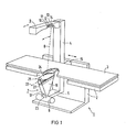
- FIG. 1 shows the structure of the X-ray examination device 1.
- a well-transparent patient support plate 3 is supported on a table frame 2. It can be moved in the longitudinal direction of the table.
- a stand column 4 is mounted displaceably in the longitudinal direction of the table.
- the stand column carries an X-ray tube 6 on a horizontal support arm 5 under the patient support plate 3.
- the blanking device 7 according to the invention is attached to this.
- the tripod column 4 carries above the patient support plate 3 a detector arrangement 9, which is exposed to the beam 8 emerging from the masking device, with individual detectors 11, 12, 13, 14 arranged closely next to one another.
- the tripod column 4 is longitudinal at a constant speed via a drive motor 15 the patient support plate 3 slidably.
- the blanking device 7 has a tube-like holder 16 which is fastened to the tube flange and has a slot aperture 18 which can be inserted at its end near the focus, in the exemplary embodiment insertable through an insertion slot 17.
- slit diaphragm 18 consists of a simple rectangular plate 19 made of radiopaque material, which is provided with a longitudinal slot 20 of constant width.
- the tube-like holder 16 Corresponding to the fan-shaped beam cone emerging from the slit diaphragm 18, the tube-like holder 16 also has a narrow, rectangular, fan-shaped cross section.
- a hollow cylinder 21 is rotatably mounted on the tube-like holder in such a way that its axis of symmetry 22 lies exactly in the plane through the slit 20 of the slit diaphragm 18 and the focus 23 of the X-ray tube 6 is formed.
- the axis of symmetry 22 of the hollow cylinder 21 is oriented approximately perpendicular to the beam direction.
- the diameter of the hollow cylinder 21 - approximately 15 cm in the exemplary embodiment - completely fills the cross section of the tubular holder 16.
- the tubular holder in the exemplary embodiment in FIG. 1 is only shown as far as the hollow cylinder 21. It could be expedient to extend the tube-like holder beyond the hollow cylinder to just below the patient support plate.
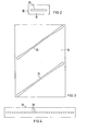
- the jacket 24 of the hollow cylinder 21 has, as shown in FIG. 1, two spiral slots 25, 26. Their shape can be seen in the development of the jacket 24 of the hollow cylinder 21 shown in FIG.
- the jacket of the hollow cylinder consists of a radiopaque plate in which the two slots 25, 26 are arranged one behind the other at an angle of approximately 45 ° to the lateral boundary.
- the two slots are widened somewhat at each end like a club (Fig. 3).
- the hollow cylinder is driven uniformly by the drive motor 15. This also shifts the stand column 4 relative to the patient support plate 3 via a gear mechanism. This shift can be selected so that the drive motor shifts the stand column by one full revolution of the hollow cylinder 21 by the width of the beam 8. The speed of the drive motor per unit of time should. can be varied to adapt to the tube performance.
- a fan-shaped beam 8 is blocked out by the slit diaphragm 18 near the focus.
- This fan-shaped radiance Bundle impinges on the other side of the tubular holder on the hollow cylinder 21 rotatably mounted there in the plane of its axis of symmetry 22.
- the x-ray radiation can only penetrate the hollow cylinder in that region of the two slots 25, 26 in which the slot on the side of the hollow cylinder facing away from the focus and the slot on the side of the hollow cylinder facing the focus are in a straight line with the focus or in other words, overlap from the focus point of view. This is only the case in a narrow rhombus-shaped area.
- the beam 8 thus blocked out penetrates the patient support plate 3, the examination object lying on the patient support plate 3 and then strikes the detector arrangement 9.
- the slit diaphragm 18 near the focus only reduces the scattered radiation which arises between the slit diaphragm and the hollow cylinder and thus the proportion of scattered radiation which can pass through the overlapping slits 25, 26 on both sides of the hollow cylinder.
- the slit of the slit diaphragm close to the focus is therefore also held somewhat further than the beam 8 passing through the hollow cylinder.
- a fluoroscopic image of the examination object can be constructed which corresponds to a conventional X-ray image. Because of the low irradiated volume, however, the amount of scattered radiation is smaller and the contrast is greater than in conventional X-ray images.
- the sharpness of the drawing grows inversely proportional to the diameter of the masked beam 8. and the distance between the individual radiation detectors. It can be increased if the advance of the stand column corresponds to only half a diameter of the blanked beam bundle instead of an entire diameter during a half revolution of the hollow cylinder 21.
- each scanned slice of the examination object overlaps with the following slice by half a beam width.
- a further increase in the sharpness of the drawing can be achieved if the detector arrangement is shifted by half a detector width in the direction of the detector line after each scanned line.
- a further insertion slot 27 is provided in the tube-like holder 16 in the immediate vicinity of the hollow cylinder 21 for a perforated diaphragm plate 28 shown in FIG. 4.
- This perforated diaphragm plate is made of a radiation-impermeable material and carries a row of holes 29 in the plane of the fan beam which is blocked by the slit diaphragm near the focus. These holes are arranged in such a way that each of them with the diaphragm plate 28 fully pushed toward a detector element 10, 11, 12 , 13, 14, the detector arrangement 9 is aligned. This ensures that the blasting Bundle 8 is faded out when the detector arrangement 9 is swept over in the area between two detectors and only those X-ray quanta that penetrate the body of the examination object that later also contribute to the image information.
- the perforated diaphragm plate shown in FIG. 4 is also possible to arrange the perforated diaphragm plate shown in FIG. 4 on the side of the hollow cylinder 21 facing away from the focus. As a result, the formation of penumbra is reduced because of the larger focal distance of the perforated diaphragm plate 28. If a linear displacement of the detectors by half a detector width is provided after each line scanned, the perforated diaphragm plate must also be displaced synchronously with the detectors by half a hole spacing. By changing the speed of the drive motor 15, the signal level of the individual detectors 10,. 11, 12, 13, 14 of the detector arrangement adapt to the dose rate of the x-ray tube 6. It is also possible to move the patient support plate 3 with the examination object with the drive motor instead of the stand column 4.
- the dimensions of the blanking device can be so small compared to the previously known solution that a reversal of the beam direction is easily possible if the x-ray tube with the blanking device is attached to the stand column 4 above the patient support plate and the detector arrangement below the patient support plate.
Abstract
Description
Die Erfindung bezieht sich auf ein Röntgenuntersuchungsgerät mit einer Patientenlagerungsplatte, mit einer auf der einen Seite der Patientenlagerungsplatte angeordneten Röntgenröhre, mit einer ein eng ausgeblendetes in einer fächerförmigen Ebene schwenkbares Röntgenstrahlenbündel erzeugenden Primärstrahlenausblendvorrichtung und mit einer auf der anderen Seite der Patientenlagerungsplatte angeordneten, dem Strahlenbündel ausgesetzten Detektoranordnung.The invention relates to an x-ray examination device with a patient support plate, with an x-ray tube arranged on one side of the patient support plate, with a primary beam blanking device producing a narrowly hidden x-ray beam that can be pivoted in a fan-shaped plane, and with a detector arrangement arranged on the other side of the patient support plate and exposed to the beam .
Es ist bereits ein Röntgenuntersuchungsgerät bekannt geworden, bei dem der aus einer Röntgenröhre austretende Strahlenkegel durch eine Schlitzblende fächerförmig eingeblendet wird und bei dem in Strahlenrichtung hinter der Schlitzblende eine radial geschlitzte kreisförmige Blendenscheibe aus strahlenundurchlässigem Material in einer Ebene senkrecht zur Strahlenrichtung drehbar gelagert ist. Das so ausgeblendete, etwa bleistiftstarke Strahlenbündel bewegt sich beim Drehen der Blendenscheibe in der Fächerebene jeweils von der einen zu der anderen Seite. Diesem Strahlenbündel ist hinter dem Untersuchungsobjekt eine Detektoranordnung zugeordnet. Beim Verschieben der Röntgenuntersuchungseinrichtung senkrecht zur Fächerebene läßt sich eine Scheibe des Untersuchungsobjektes nach der anderen abtasten. Die Meßwerte der einzelnen zeilenweise angeordneten Detektoren lassen sich speichern und auf einem Fernsehsichtgerät zeitweise in verschiedenen Graustufen abbilden. Das Bild entspricht einer konventionellen Röntgenaufnahme. Jedoch ist der Streustrahlenanteil wegen des jeweils relativ kleinen,von Röntgenstrahlen durchsetzten Volumens gering. Es ist eine Eigenart dieser Anordnung, daß sich die Form des ausgeblendeten Strahlenbündels während des Drehens der Blendenscheibe über der schlitzartigen Ausblendung ändert. Auch muß die Blendenscheibe einen deutlich größeren Durchmesser haben als die Breite des ausgeblendeten Strahlenfächers in der Ebene der Blendenscheibe. Dies führt dazu, daß die gesamte Ausblendanordnung so voluminös wird, daß sie nur bei Untertischröhrengeräten einsetzbar ist. Aber auch dort zeigt sich, daß beim Verschieben in Tischlängsrichtung nur ein Teil des Längshubes ausnutzbar ist, weil anderenfalls die geschlitzte Blendenscheibe an der Stirnseite des Tischgestells anstoßen würde.An X-ray examination device has already become known in which the beam cone emerging from an X-ray tube is fanned in by a slit diaphragm and in which a radially slotted circular diaphragm disk made of radiopaque material is rotatably mounted in a plane perpendicular to the beam direction behind the slit diaphragm in the beam direction. The beam, which is masked out in this way and is pencil-strong, moves from one side to the other when the aperture disk is rotated in the fan plane. A detector arrangement is assigned to this beam behind the examination object. When moving the X-ray examination device perpendicular to the fan plane, one slice of the examination object can be scanned after the other. The measured values of the individual detectors arranged in rows can be stored and temporarily displayed on a television viewing device in different shades of gray. The image corresponds to a conventional x-ray. However, the scattered radiation due to the relatively small volume penetrated by X-rays. It is a peculiarity of this arrangement that the shape of the blanked beam changes during the rotation of the diaphragm disk over the slit-like blanking. The diaphragm disc must also have a significantly larger diameter than the width of the masked beam fan in the plane of the diaphragm disc. This leads to the fact that the entire blanking arrangement becomes so voluminous that it can only be used with under-table tube devices. But even there it shows that only part of the longitudinal stroke can be used when moving in the longitudinal direction of the table, because otherwise the slotted diaphragm disc would abut the front of the table frame.
Der Erfindung liegt die Aufgabe zugrunde, den Untersuchungsbereich bei Röntgenuntersuchungsgeräten,die das Untersuchungsobjekt mit einem eng ausgeblendeten Röntgenstrahl zeilenförmig abtasten, zu vergrößern. Auch soll eine konstruktive Lösung gefunden werden, die es gestatten, bei einem solchen Röntgenuntersuchungsgerät unter Umkehrung der Strahlenrichtung mit einer Obertischröntgenröhre und einer Untertischaufnahmeeinrichtung zu arbeiten.The object of the invention is to enlarge the examination area in the case of X-ray examination devices which scan the examination object in a line shape with a closely masked X-ray beam. A constructive solution is also to be found which makes it possible to work with such an x-ray examination apparatus by reversing the direction of the radiation with an upper table x-ray tube and a lower table receiving device.
Bei einem Röntgenuntersuchungsgerät der eingangs genannten Art enthält daher erfindungsgemäß die Ausblendvorrichtung einen mit seiner Symmetrieachse in etwa senkrecht zur Strahlenrichtung ausgerichteten, gleichmäßig angetriebenen Hohlzylinder, dessen strahlenundurchlässige Wandung zwei um 180 gegeneinander versetzte spiralförmige Schlitze trägt. Ein solcher Hohlzylinder läßt die Strahlung nur in dem Bereich durch, in dem sich die beiden Schlitze auf der in Strahlenrichtung gesehen vorderen und hinteren Seite der Mantelfläche in einer Linie mit dem Fokus befinden. Dies ist stets nur in einem einzigen Punkt der Fall. Dieser Punkt wandert bei der Drehung des Hohlzylinders in axialer Richtung. Das ausgeblendete Strahlenbündel hat einenrhonbenförmigen Querschnitt. Es ist ein großer Vorteil dieser Konstruktion, daß die Ausblendvorrichtung nur wenig Platz senkrecht zur Fächerebene benötigt. Bei der Verwendung mit einer Untertischröntgenröhre wird so der Längshub unterhalb des Tischgestells nicht behindert. Aus demselben Grund eignet sich diese Ausblendvorrichtung auch besonders für Röntgenuntersuchungsgeräte, bei denen sich die Röntgenröhre mitsamt der Ausblendvorrichtung oberhalb und die Detektoren unterhalb der Patientenlagerungsplatte befinden.In the case of an X-ray examination apparatus of the type mentioned at the outset, the masking device therefore contains, according to the invention, a hollow cylinder which is aligned with its axis of symmetry and approximately perpendicular to the beam direction and whose radiopaque wall bears two spiral slots offset by 180 from one another. Such a hollow cylinder allows the radiation to pass only in the area in which the two slits are located in the beam seen in the direction of the front and rear side of the lateral surface are in a line with the focus. This is always the case in only one point. This point moves in the axial direction when the hollow cylinder rotates. The blanked-out beam has a rhombic cross-section. It is a great advantage of this construction that the blanking device takes up little space perpendicular to the fan plane. When used with an under-table X-ray tube, the longitudinal stroke underneath the table frame is not hindered. For the same reason, this blanking device is also particularly suitable for X-ray examination devices in which the X-ray tube together with the blanking device are above and the detectors below the patient support plate.
Die Ausblendvorrichtung läßt sich auch für größere Fächerwinkel verwenden, wenn die Schlitzbreite in besonders vorteilhafter Weiterbildung der Erfindung von der Schlitzmitte zu ihren Enden hin verbreitert ist. Dies hat den Verteil, daß auch bei der an seinen beiden Enden schrägen Durchstrahlung des Hohlzylinders der unterschiedlich axial verschobene Auftreffpunkt des Strahlenbündels auf der der Strahlenquelle zugewandten und der von ihr abgewandten Seite des Hohlzylinders zu keiner Verschmälerung des durchgelassenen Strahlenbündels führt.The blanking device can also be used for larger fan angles if, in a particularly advantageous development of the invention, the slot width is widened from the slot center to its ends. This has the distribution that even in the case of the oblique irradiation of the hollow cylinder at both ends, the different axially displaced point of incidence of the beam on the side facing the radiation source and the side of the hollow cylinder facing away from it does not lead to any narrowing of the transmitted beam.
In zweckmäßiger Ausgestaltung der Erfindung kann der Hohlzylinder zwischen Strahlenquelle und Patientenlagerungsplatte fokusfern am Ende einer tubusartigen Halterung gelagert sein. Diese Konstruktion verringert die Halbschattenbildung und verhindert zugleich das Austreten von Streustrahlung im Bereich der Ausblendvorrichtung.In an expedient embodiment of the invention, the hollow cylinder between the radiation source and the patient support plate can be mounted at the end of a tube-like holder away from the focus. This construction reduces the formation of penumbra and at the same time prevents stray radiation from escaping in the area of the masking device.
In vorteilhafter Ausgestaltung der Erfindung kann in der durch den Fokus und die Symmetrieachse des Hohlzylinders gegebenen Ebene eine zusätzliche fokusnahe schlitzförmige Einblendung angeordnet sein. Hierdurch läßt sich die aus dem Schlitz austretende Streustrahlung noch weiter vermindern.und läßt sich daher auch die Schärfe des ausgeblendeten Strahlenbündels noch weiter steigern.In an advantageous embodiment of the invention, an additional slot-like overlay near the focus can be arranged in the plane given by the focus and the axis of symmetry of the hollow cylinder. As a result, the scattered radiation emerging from the slit can be reduced even further, and the sharpness of the masked beam can also be further increased.
Die Strahlenbelastung des Patienten kann noch weiter verringert werden, wenn in besonders zweckmäßiger Weiterbildung der Erfindung eine Blendenplatte in den Strahlengang zwischen Röntgenröhre und Patientenlagerungsplatte eingesetzt ist, die auf die einzelnen Detektorelemente der Detektoranordnung ausgerichtete Löcher trägt. Hierdurch wird jedes einzelne Detektorelement für sich gesondert bestrahlt, während die Zwischenzonen geschont werden.The radiation exposure of the patient can be reduced even further if, in a particularly expedient development of the invention, an aperture plate is inserted into the beam path between the X-ray tube and the patient support plate, which bores are aligned with the individual detector elements of the detector arrangement. As a result, each individual detector element is irradiated separately, while protecting the intermediate zones.
Weitere Einzelheiten der Erfindung werden anhand eines in den Figuren dargestellten Ausführungsbeispiels erläutert. Es zeigen:
- Fig. 1 eine schaubildliche Ansicht des Röntgenuntersuchungsgerätes mit einer erfindungsgemäßen Primärstrahlenausblendvorrichtung,
- Fig. 2 eine Aufsicht auf eine in die Ausblendvorrichtung einsetzbare fokusnahe Schlitzblende,
- Fig. 3 eine Darstellung der Abwicklung des Hohlzylinders der Primärstrahlenausblendungsvorrichtung und
- Fig. 4 eine Aufsicht auf eine in der Ausblendvorrichtung einsetzbare gelochte Blendenplatte.
- 1 is a perspective view of the X-ray examination device with a primary beam blanking device according to the invention,
- 2 is a plan view of a slit diaphragm which is near the focus and can be inserted into the masking device,
- Fig. 3 shows the development of the hollow cylinder of the primary beam blanking device and
- Fig. 4 is a plan view of a perforated diaphragm plate which can be used in the masking device.
Die Fig. 1 läßt den Aufbau des Röntgenuntersuchungsgerätes 1 erkennen. Auf einem Tischgestell 2 lagert eine gut strahlendurchlässige Patientenlagerungsplatte 3. Sie ist in Tischlängsrichtung verschiebbar. An der in der Darstellung der Fig. 1 hinteren Längsseite des Tischgestells 2 ist eine Stativsäule 4 in Tischlängsrichtung verschiebbar gelagert. Die Stativsäule trägt unter der Patientenlagerungsplatte 3 an einem horizontalen Tragarm 5 eine Röntgenröhre 6. An dieser ist die erfindungsgemäße Ausblendvorrichtung 7 befestigt. Die Stativsäule 4 trägt oberhalb der Patientenlagerungsplatte 3 eine, dem aus der Ausblendvorrichtung austretenden Strahlenbündel 8 ausgesetzte Detektoranordnung 9, mit in einer Reihe dicht nebeneinander angeordneter Einzeldetektoren 11, 12, 13, 14. Außerdem ist die Stativsäule 4 über einen Antriebsmotor 15 mit konstanter Geschwindigkeit längs der Patientenlagerungsplatte 3 verschiebbar.1 shows the structure of the X-ray examination device 1. A well-transparent
Die Ausblendvorrichtung 7 besitzt eine am Röhrenflansch befestigte tubusartige Halterung 16, die an ihrem fokusnahen Ende einc, im Ausführungsbeispiel durch einen Einschubschlitz 17 einsetzbare Schlitzblende 18 trägt. Diese, in der Fig. 2 in Aufsicht dargestellte, Schlitzblende 18 besteht aus einer einfachen rechteckigen Platte 19 aus strahlenundurchlässigem Material, die mit einem Längsschlitz 20 konstanter Breite versehen ist. Entsprechend dem aus der Schlitzblende 18 austretenden fächerförmigen Strahlenkegel hat auch die tubusartige Halterung 16 einen schmalen, rechteckigen, fächerförmigen Querschnitt. An dem der Schlitzblende 18 abgewandten fokusfernen Ende der tubusartigen Halterung 16 ist ein Hohlzylinder 21 dergestalt an der tubusartigen Halterung drehbar gelagert, daß seine Symmetrieachse 22 genau in der Ebene liegt, die durch den Schlitz 20 der Schlitzblende 18 und dem Fokus 23 der Röntgenröhre 6 gebildet wird. Außerdem ist die Symmetrieachse 22 des Hohlzylinders 21 in etwa senkrecht zur Strahlenrichtung ausgerichtet. Der Durchmesser des Hohlzylinders 21 - im Ausführungsbeispiel etwa 15 cm - füllt den Querschnitt der tubusartigen Halterung 16 vollständig aus. Der Übersichtlichkeit halber ist die tubusartige Halterung im Ausführungsbeispiel der Fig. 1 nur bis an den Hohlzylinder 21 herangeführt dargestellt. Es könnte zweckmäßig sein, die tubusartige Halterung über den Hohlzylinder hinaus bis unmittelbar unter die Patientenlagerungsplatte zu verlängern.The
Der Mantel 24 des Hohlzylinders 21 besitzt, wie die Fig. 1 zeigt, zwei spiralförmige Schlitze 25, 26. Ihre Form ist der in der Fig. 2 gezeigten Abwicklung des Mantels 24 des Hohlzylinders 21 zu entnehmen. Der Mantel des Hohlzylinders besteht aus einer strahlenundurchlässigen Platte, in der die beiden Schlitze 25,26 in einem Winkel von etwa 45° zur seitlichen Begrenzung, hintereinander angeordnet sind. Die beiden Schlitze sind an ihren beiden Enden jeweils etwas keulenartig verbreitert (Fig. 3).The
Der Hohlzylinder wird von dem Antriebsmotor 15 gleichmäßig angetrieben. Dieser verschiebt zuglich auch über ein Getriebe die Stativsäule 4 relativ zur Patientenlagerungsplatte 3. Diese Verschiebung kann so gewählt werden, daß der Antriebsmotor die Stativsäule jeweils nach einer vollen Umdrehung des Hohlzylinders 21 um die Breite des Strahlenbündels 8 verschiebt. Die Drehzahl des Antriebsmotors je Zeiteinheit soll. zur Anpassung an die Röhrenleistung variiert werden können.The hollow cylinder is driven uniformly by the
Beim Einschalten der Röntgenröhre wird ein fächerförmiges Strahlenbündel 8 durch die fokusnahe Schlitzblende 18 ausgeblendet. Dieses fächerförmige Strahlenbündel trifft auf der anderen Seite der tubusartigen Halterung auf den dort drehbar gelagerten Hohlzylinder 21 in der Ebene seiner Symmetrieachse 22 auf. Die Röntgenstrahlung kann den Hohlzylinder nur in demjenigen Bereich der beiden Schlitze 25, 26 durchdringen, in dem sich der Schlitz auf der dem Fokus abgewandten Seite des Hohlzylinders und der Schlitz auf der dem Fokus zugewandten Seite des Hohlzylinders in einer geraden Linie mit dem Fokus befinden oder anders ausgedrückt sich aus der Sicht des Fokus überdecken. Dies ist nur in einem schmalen rhombusförmigen Flächenbereich der Fall. Das so ausgeblendete Strahlenbündel 8 durchdringt die Patientenlagerungsplatte 3, das auf der Patientenlagerungsplatte 3 liegende Untersuchungsobjekt und trifft dann auf die Detektoranordnung 9 auf.When the X-ray tube is switched on, a fan-shaped beam 8 is blocked out by the
Die fokusnahe Schlitzblende 18 verringert lediglich die zwischen Schlitzblende und Hohlzylinder entstehende Streustrahlung und damit den Streustrahlenanteil der durch die sich überschneidenden Schlitze 25, 26 auf den beiden Seiten des Hohlzylinders hindurchtreten kann. Der Schlitz der fokusnahen Schlitzblende ist daher auch etwas weiter gehalten als das durch den Hohlzylinder durchgehende Strahlenbündel 8. Beim Drehen des Hohlzylinders wandert das Strahlenbündel 8 längs der Symmetrieachse 22 des Hohlzylinders 21. Die Richtung in der das Strahlenbündel 8 wandert, ist durch die Drehrichtung des Hohlzylinders vorgegeben. Dabei überstreicht das Strahlenbündel während jeder halben Umdrehung des Hohlzylinders die gesamte Ausdehnung der Detektoranordnung 9, d.h. die in einer Reihe angeordneten Einzeldetektoren 10, 11, 12, 13, 14. Bei gleichzeitigem Verschieben der Stativsäule läßt sich das Untersuchungsobjekt Scheibe für Scheibe abtasten.The
Durch zeilenweises Aufzeichnen der Meßwerte der einzelnen Detektoren 10, 11, 12, 13, 14 der Detektoranordnung 9 auf dem Leuchtschirm eines Fernsehsichtgerätes (nicht dargestellt) läßt sich ein Durchleuchtungsbild des Untersuchungsobjektes konstruieren, das einer herkömmlichen Röntgenaufnahme entspricht. Wegen des geringen durchstrahlten Volumens ist jedoch der Streustrahlenanteil kleiner und-der Kontrast größer als bei herkömmlichen Röntgenaufnahmen. Die Zeichenschärfe wächst umgekehrt proportional mit dem Durchmesser des ausgeblendeten Strahlenbündels 8.und dem Abstand der einzelnen Strahlendetektoren voneinander. Sie läßt sich erhöhen, wenn der Vorschub der Stativsäule bei einer halben Umdrehung des Hohlzylinders 21 nur einem halben statt einem ganzen Durchmesser des ausgeblendeten Strahlenbündels entspricht. In diesem Fall überlappt sich jede abgetastete Scheibe des Untersuchungsobjektes mit der nachfolgenden Scheibe um eine halbe Strahlenbündelbreite. Eine weitere Steigerung der Zeichenschärfe läßt sich erreichen, wenn die Detektoranordnung nach jeder abgetasteten Zeile um eine halbe Detektorbreite in Richtung der Detektorzeile verschoben -wird.By line-by-line recording of the measured values of the
Im Ausführungsbeispiel ist in der tubusartigen Halterung 16 in unmittelbarer Nachbarschaft zum Hohlzylinder 21 ein weiterer Einschubschlitz 27 für eine in der Fig. 4 dargestellte gelochte Blendenplatte 28 vorgesehen. Diese gelochte Blendenplatte besteht aus einem strahlenundurchlässigen Material und trägt in der Ebene des von der fokusnahen Schlitzblende ausgeblendeten Strahlenfächers eine Reihe von Löchern 29. Diese Löcher sind so angeordnet, daß ein jedes von ihnen bei völlig ehgeschobener Blendenplatte 28 zu einem Detektorelement 10, 11, 12, 13, 14,der Detektoranordnung 9 ausgerichtet ist. Hierdurch wird sichergestellt, daß das StrahlenbUndel 8 beim Überstreichen der Detektoranordnung 9 in dem Bereich zwischen zwei Detektoren ausgeblendet wird und nur jene Röntgenquanten den Körper des Untersuchungsobjektes durchsetzen, die später auch zur Bildinformation beitragen.In the exemplary embodiment, a
Es ist auch möglich, die in Fig. 4 dargestellte gelochte Blendenplatte auf der dem Fokus abgewandten Seite des Hohlzylinders 21 anzuordnen. Hierdurch wird die Halbschattenbildung wegen der größeren Fokusferne der gelochten Blendenplatte 28 verringert. Ist eine lineare Verschiebung der Detektoren um eine halbe Detektorbreite nach jeder abgetasteten Zeile vorgesehen, so muß auch die gelochte Blendenplatte synchron mit den Detektoren um einen halben Lochabstand verschoben werden. Durch Änderung der Drehzahl des Antriebsmotors 15 läßt sich die Signalhöhe der einzelnen Detektoren 10, . 11, 12, 13, 14 der Detektoranordnung an die Dosisleistung der Röntgenröhre 6 anpassen. Dabei ist es auch möglich, mit dem Antriebsmotor statt der Stativsäule 4 die Patientenlagerungsplatte 3 mit dem Untersuchungsobjekt zu verschieben. Die Ausblendvorrichtung läßt sich in ihren Abmessungen verglichen mit der vorbekannten Lösung so klein bauen, daß damit ohne weiteres eine Umkehrung der Strahlenrichtung möglich wird, wenn die Röntgenröhre mit der Ausblendvorrichtung oberhalb der Patientenlagerungsplatte und die Detektoranordnung unterhalb der Patientenlagerungsplatte an der Stativsäule 4 befestigt wird.It is also possible to arrange the perforated diaphragm plate shown in FIG. 4 on the side of the
Claims (11)
Applications Claiming Priority (2)
| Application Number | Priority Date | Filing Date | Title |
|---|---|---|---|
| DE3135421 | 1981-09-07 | ||
| DE19813135421 DE3135421A1 (en) | 1981-09-07 | 1981-09-07 | X-RAY EXAMINATION DEVICE |
Publications (2)
| Publication Number | Publication Date |
|---|---|
| EP0074021A1 true EP0074021A1 (en) | 1983-03-16 |
| EP0074021B1 EP0074021B1 (en) | 1985-11-21 |
Family
ID=6141071
Family Applications (1)
| Application Number | Title | Priority Date | Filing Date |
|---|---|---|---|
| EP82107827A Expired EP0074021B1 (en) | 1981-09-07 | 1982-08-25 | X-ray examination apparatus |
Country Status (3)
| Country | Link |
|---|---|
| EP (1) | EP0074021B1 (en) |
| JP (1) | JPS5850941A (en) |
| DE (2) | DE3135421A1 (en) |
Cited By (7)
| Publication number | Priority date | Publication date | Assignee | Title |
|---|---|---|---|---|
| EP0184247A2 (en) * | 1984-11-27 | 1986-06-11 | Philips Patentverwaltung GmbH | Arrangement for examining a body by gamma or X-rays |
| EP0357146A2 (en) * | 1988-09-01 | 1990-03-07 | Philips Patentverwaltung GmbH | Arrangement for generating an X-ray or gamma-ray with a small sectional area and variable direction |
| EP0389033A2 (en) * | 1989-03-18 | 1990-09-26 | Philips Patentverwaltung GmbH | X or gamma ray generation apparatus with small cross-section and variable position |
| WO2002082065A2 (en) * | 2001-04-03 | 2002-10-17 | Koninklijke Philips Electronics N.V. | Computed tomography apparatus |
| EP1772874A2 (en) * | 2005-10-06 | 2007-04-11 | Bundesanstalt Für Materialforschung Und -Prufung (Bam) | Focal point oriented aperture |
| US10082473B2 (en) | 2015-07-07 | 2018-09-25 | General Electric Company | X-ray filtration |
| CN110507351A (en) * | 2019-08-13 | 2019-11-29 | 孙立磊 | A kind of dept. of radiology's New video inspection auxiliary device |
Families Citing this family (2)
| Publication number | Priority date | Publication date | Assignee | Title |
|---|---|---|---|---|
| US4879345A (en) * | 1988-07-27 | 1989-11-07 | Ppg Industries, Inc. | Fluoropolymer based coating composition for adhesion direct to glass |
| US5008153A (en) * | 1988-12-08 | 1991-04-16 | Ppg Industries, Inc. | Corrosion inhibitive pretreatment for "copper-free" mirrors |
Citations (5)
| Publication number | Priority date | Publication date | Assignee | Title |
|---|---|---|---|---|
| US3780291A (en) * | 1971-07-07 | 1973-12-18 | American Science & Eng Inc | Radiant energy imaging with scanning pencil beam |
| US4031401A (en) * | 1975-03-14 | 1977-06-21 | American Science & Engineering, Inc. | Radiant energy imaging scanning |
| EP0024028A1 (en) * | 1979-08-08 | 1981-02-18 | Siemens Aktiengesellschaft | X-ray apparatus for tomography and shadow radiography |
| US4266135A (en) * | 1977-07-01 | 1981-05-05 | Ohio Nuclear, Inc. | Method of determining collimator aperture efficiency and apparatus with an efficient collimator aperture size |
| FR2482444A1 (en) * | 1980-05-19 | 1981-11-20 | American Science & Eng Inc | X-RAY CALCULATED TOMOGRAPHY APPARATUS USING A FLOATING SPOT MECHANICAL MECHANISM |
-
1981
- 1981-09-07 DE DE19813135421 patent/DE3135421A1/en not_active Withdrawn
-
1982
- 1982-08-25 DE DE8282107827T patent/DE3267605D1/en not_active Expired
- 1982-08-25 EP EP82107827A patent/EP0074021B1/en not_active Expired
- 1982-09-06 JP JP57155089A patent/JPS5850941A/en active Pending
Patent Citations (5)
| Publication number | Priority date | Publication date | Assignee | Title |
|---|---|---|---|---|
| US3780291A (en) * | 1971-07-07 | 1973-12-18 | American Science & Eng Inc | Radiant energy imaging with scanning pencil beam |
| US4031401A (en) * | 1975-03-14 | 1977-06-21 | American Science & Engineering, Inc. | Radiant energy imaging scanning |
| US4266135A (en) * | 1977-07-01 | 1981-05-05 | Ohio Nuclear, Inc. | Method of determining collimator aperture efficiency and apparatus with an efficient collimator aperture size |
| EP0024028A1 (en) * | 1979-08-08 | 1981-02-18 | Siemens Aktiengesellschaft | X-ray apparatus for tomography and shadow radiography |
| FR2482444A1 (en) * | 1980-05-19 | 1981-11-20 | American Science & Eng Inc | X-RAY CALCULATED TOMOGRAPHY APPARATUS USING A FLOATING SPOT MECHANICAL MECHANISM |
Non-Patent Citations (1)
| Title |
|---|
| PATENTS ABSTRACTS OF JAPAN, Band 1, Nr. 152, 7. Dezember 1977, Seite 8032E77 & JP - A - 52 93384 (SHIMAZU SEISAKUSHO K.K.) 08.05.1977 * |
Cited By (15)
| Publication number | Priority date | Publication date | Assignee | Title |
|---|---|---|---|---|
| EP0184247A3 (en) * | 1984-11-27 | 1987-06-16 | Philips Patentverwaltung Gmbh | Arrangement for examining a body by gamma or x-rays |
| EP0184247A2 (en) * | 1984-11-27 | 1986-06-11 | Philips Patentverwaltung GmbH | Arrangement for examining a body by gamma or X-rays |
| EP0357146A3 (en) * | 1988-09-01 | 1991-03-27 | Philips Patentverwaltung GmbH | Arrangement for generating an x-ray or gamma-ray with a small sectional area and variable direction |
| EP0357146A2 (en) * | 1988-09-01 | 1990-03-07 | Philips Patentverwaltung GmbH | Arrangement for generating an X-ray or gamma-ray with a small sectional area and variable direction |
| US4995066A (en) * | 1988-09-01 | 1991-02-19 | U. S. Philips Corporation | Device for forming an X-ray or gamma beam of small cross-section and variable direction |
| EP0389033A3 (en) * | 1989-03-18 | 1991-07-31 | Philips Patentverwaltung GmbH | X or gamma ray generation apparatus with small cross-section and variable position |
| EP0389033A2 (en) * | 1989-03-18 | 1990-09-26 | Philips Patentverwaltung GmbH | X or gamma ray generation apparatus with small cross-section and variable position |
| US5038370A (en) * | 1989-03-18 | 1991-08-06 | U.S. Philips Corporation | Directional variable small cross-sectional X-ray or gamma ray beam generating diaphragm with rotating helical slits |
| WO2002082065A2 (en) * | 2001-04-03 | 2002-10-17 | Koninklijke Philips Electronics N.V. | Computed tomography apparatus |
| WO2002082065A3 (en) * | 2001-04-03 | 2003-02-13 | Koninkl Philips Electronics Nv | Computed tomography apparatus |
| US6744845B2 (en) | 2001-04-03 | 2004-06-01 | Koninklijke Philips Electronics N.V. | Computed tomography apparatus for determining the pulse momentum transfer spectrum |
| EP1772874A2 (en) * | 2005-10-06 | 2007-04-11 | Bundesanstalt Für Materialforschung Und -Prufung (Bam) | Focal point oriented aperture |
| EP1772874A3 (en) * | 2005-10-06 | 2007-08-22 | Bundesanstalt Für Materialforschung Und -Prufung (Bam) | Focal point oriented aperture |
| US10082473B2 (en) | 2015-07-07 | 2018-09-25 | General Electric Company | X-ray filtration |
| CN110507351A (en) * | 2019-08-13 | 2019-11-29 | 孙立磊 | A kind of dept. of radiology's New video inspection auxiliary device |
Also Published As
| Publication number | Publication date |
|---|---|
| JPS5850941A (en) | 1983-03-25 |
| DE3135421A1 (en) | 1983-03-24 |
| EP0074021B1 (en) | 1985-11-21 |
| DE3267605D1 (en) | 1986-01-02 |
Similar Documents
| Publication | Publication Date | Title |
|---|---|---|
| DE112005001757B4 (en) | X-ray device with a single-sheet X-ray collimator | |
| DE2559658A1 (en) | RADIOGRAPHIC DEVICE | |
| DE2657898C2 (en) | Transaxial tomography scintillation camera | |
| DE602004012080T2 (en) | IDENTIFYING IONIZING RADIATION TO DUAL ENERGY SCANNING BASIS | |
| EP1772874B1 (en) | Focal point oriented aperture | |
| DE2709600C2 (en) | Computer tomograph | |
| EP2168490A1 (en) | X-ray device for breast examination with source-detector arrangement for high resolution imaging | |
| EP1089297A2 (en) | Grid for X-ray absorption | |
| DE19908494A1 (en) | Computer tomography unit with gantry movement independent of patients couch | |
| EP1623672A1 (en) | X-ray apparatus, in particular for a device for x-ray mammography | |
| WO2004026141A1 (en) | Computed tomography apparatus comprising a fade-in device at the emitter end, and method for operating such a computed tomography apparatus | |
| DE10244898B4 (en) | Insertion device and computed tomography device with a radiator-side insertion device | |
| DE3829688A1 (en) | ARRANGEMENT FOR GENERATING A X-RAY OR GAMMA RAY WITH A SMALL SECTION AND CHANGING DIRECTION | |
| EP0074021B1 (en) | X-ray examination apparatus | |
| DE2404194A1 (en) | RADIATION COLLIMATOR | |
| DE2619482C2 (en) | X-ray film device for the production of transverse slice images | |
| DE3443095A1 (en) | ARRANGEMENT FOR EXAMINING A BODY WITH GAMMA OR X-RAY RADIATION | |
| DE2714759B2 (en) | X-ray diagnostic device for the production of transverse slice images | |
| EP1177767B1 (en) | Computer tomograph with coneshaped beam and helicoidal relative movement | |
| DE4435112C2 (en) | Device for aligning an x-ray cassette | |
| EP0632994B1 (en) | X-ray diagnostic device for producing X-rays of body parts of a patient | |
| DE2446680B2 (en) | Tube for limiting a bundle of penetrating rays | |
| DE2912010A1 (en) | DEVICE FOR MEASURING THE ABSORPTION DISTRIBUTION | |
| DE10356601B4 (en) | Apparatus for X-ray tomography with an electronically deflected electron beam | |
| DE3106264A1 (en) | SCREENING DEVICE |
Legal Events
| Date | Code | Title | Description |
|---|---|---|---|
| PUAI | Public reference made under article 153(3) epc to a published international application that has entered the european phase |
Free format text: ORIGINAL CODE: 0009012 |
|
| AK | Designated contracting states |
Designated state(s): DE FR |
|
| 17P | Request for examination filed |
Effective date: 19830405 |
|
| GRAA | (expected) grant |
Free format text: ORIGINAL CODE: 0009210 |
|
| AK | Designated contracting states |
Designated state(s): DE FR |
|
| PG25 | Lapsed in a contracting state [announced via postgrant information from national office to epo] |
Ref country code: FR Free format text: THE PATENT HAS BEEN ANNULLED BY A DECISION OF A NATIONAL AUTHORITY Effective date: 19851121 |
|
| REF | Corresponds to: |
Ref document number: 3267605 Country of ref document: DE Date of ref document: 19860102 |
|
| EN | Fr: translation not filed | ||
| PLBE | No opposition filed within time limit |
Free format text: ORIGINAL CODE: 0009261 |
|
| STAA | Information on the status of an ep patent application or granted ep patent |
Free format text: STATUS: NO OPPOSITION FILED WITHIN TIME LIMIT |
|
| 26N | No opposition filed | ||
| PG25 | Lapsed in a contracting state [announced via postgrant information from national office to epo] |
Ref country code: DE Effective date: 19870501 |