EP0067061A1 - Azimuthal magnetic recording and reproducing apparatus - Google Patents
Azimuthal magnetic recording and reproducing apparatus Download PDFInfo
- Publication number
- EP0067061A1 EP0067061A1 EP82302924A EP82302924A EP0067061A1 EP 0067061 A1 EP0067061 A1 EP 0067061A1 EP 82302924 A EP82302924 A EP 82302924A EP 82302924 A EP82302924 A EP 82302924A EP 0067061 A1 EP0067061 A1 EP 0067061A1
- Authority
- EP
- European Patent Office
- Prior art keywords
- head
- magnetic
- recording
- magnetic tape
- gaps
- Prior art date
- Legal status (The legal status is an assumption and is not a legal conclusion. Google has not performed a legal analysis and makes no representation as to the accuracy of the status listed.)
- Granted
Links
Images


Classifications
-
- G—PHYSICS
- G11—INFORMATION STORAGE
- G11B—INFORMATION STORAGE BASED ON RELATIVE MOVEMENT BETWEEN RECORD CARRIER AND TRANSDUCER
- G11B15/00—Driving, starting or stopping record carriers of filamentary or web form; Driving both such record carriers and heads; Guiding such record carriers or containers therefor; Control thereof; Control of operating function
- G11B15/02—Control of operating function, e.g. switching from recording to reproducing
- G11B15/05—Control of operating function, e.g. switching from recording to reproducing by sensing features present on or derived from record carrier or container
- G11B15/06—Control of operating function, e.g. switching from recording to reproducing by sensing features present on or derived from record carrier or container by sensing auxiliary features on record carriers or containers, e.g. to stop machine near the end of a tape
-
- G—PHYSICS
- G11—INFORMATION STORAGE
- G11B—INFORMATION STORAGE BASED ON RELATIVE MOVEMENT BETWEEN RECORD CARRIER AND TRANSDUCER
- G11B5/00—Recording by magnetisation or demagnetisation of a record carrier; Reproducing by magnetic means; Record carriers therefor
- G11B5/48—Disposition or mounting of heads or head supports relative to record carriers ; arrangements of heads, e.g. for scanning the record carrier to increase the relative speed
- G11B5/488—Disposition of heads
- G11B5/4893—Disposition of heads relative to moving tape
-
- G—PHYSICS
- G11—INFORMATION STORAGE
- G11B—INFORMATION STORAGE BASED ON RELATIVE MOVEMENT BETWEEN RECORD CARRIER AND TRANSDUCER
- G11B5/00—Recording by magnetisation or demagnetisation of a record carrier; Reproducing by magnetic means; Record carriers therefor
- G11B5/48—Disposition or mounting of heads or head supports relative to record carriers ; arrangements of heads, e.g. for scanning the record carrier to increase the relative speed
- G11B5/49—Fixed mounting or arrangements, e.g. one head per track
- G11B5/4969—Details for track selection or addressing
-
- G—PHYSICS
- G11—INFORMATION STORAGE
- G11B—INFORMATION STORAGE BASED ON RELATIVE MOVEMENT BETWEEN RECORD CARRIER AND TRANSDUCER
- G11B5/00—Recording by magnetisation or demagnetisation of a record carrier; Reproducing by magnetic means; Record carriers therefor
- G11B5/48—Disposition or mounting of heads or head supports relative to record carriers ; arrangements of heads, e.g. for scanning the record carrier to increase the relative speed
- G11B5/54—Disposition or mounting of heads or head supports relative to record carriers ; arrangements of heads, e.g. for scanning the record carrier to increase the relative speed with provision for moving the head into or out of its operative position or across tracks
- G11B5/55—Track change, selection or acquisition by displacement of the head
- G11B5/5504—Track change, selection or acquisition by displacement of the head across tape tracks
-
- G—PHYSICS
- G11—INFORMATION STORAGE
- G11B—INFORMATION STORAGE BASED ON RELATIVE MOVEMENT BETWEEN RECORD CARRIER AND TRANSDUCER
- G11B5/00—Recording by magnetisation or demagnetisation of a record carrier; Reproducing by magnetic means; Record carriers therefor
- G11B5/48—Disposition or mounting of heads or head supports relative to record carriers ; arrangements of heads, e.g. for scanning the record carrier to increase the relative speed
- G11B5/54—Disposition or mounting of heads or head supports relative to record carriers ; arrangements of heads, e.g. for scanning the record carrier to increase the relative speed with provision for moving the head into or out of its operative position or across tracks
- G11B5/55—Track change, selection or acquisition by displacement of the head
- G11B5/5513—Specially adapted for transducing in both travelling directions of tape
Definitions
- This invention relates to an azimuthal magnetic recording and reproducing apparatus in which each of a plurality of recording tracks extending in the longitudinal direction of a magnetic tape is magnetized in a direction different from that of the adjacent one so that an information signal can be recorded on the recording tape in a high recording density and can then be reproduced therefrom.
- a recorder such as a tape recorder or a data recorder using a magnetic tape
- the technique is commonly known according to which an information signal is recorded on and reproduced from a plurality of tracks arranged in parallel to each other in the widthwise direction of the magnetic tape, that is, in the direction orthogonal with respect to the travelling direction of the magnetic tape.
- the magnetic tape is driven in the forward and backward directions or is driven once in one direction or is repeatedly driven in one direction only, and a magnetic head having a very small width is used for the purpose of recording and reproduction.
- the magnetic head used for this purpose has a single head gap or a plurality of head gaps.
- the magnetic head having the single head gap When the magnetic head having the single head gap is used, the magnetic head is moved in the widthwise direction of the magnetic tape each time the magnetic tape has been driven in a predetermined direction.
- the magnetic head having the plural head gaps when used, the operating head gaps are sequentially electrically switched over each time the magnetic tape has been driven in the forward and backward directions.
- the magnetic head of the type in which the head gaps are sequentially electrically switched over is superior in the structural aspect to the magnetic head of the single head gap type, since the former does not require complex means for displacing or moving the magnetic head relative to the magnetic tape.
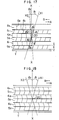
- FIG. 1 is a perspective view of such a prior art magnetic head used for two-way recording and reproduction.
- the magnetic head 1 is shown to include two head gaps 2 1 and 2 2 to be used for forward scanning and two head gaps 2 1 ' and 2 2 T to be used for backward scanning and is supported on a head support 3.
- FIG. 2 shows schematically patterns recorded on a magnetic tape T by the magnetic head 1 shown in FIG. 1.
- the magnetic tape T includes recording tracks 5 1 and 5 2 recorded with information during the travel of the magnetic tape T in the forward direction (which tracks will be referred to hereinafter as forward recording tracks), recording tracks 6 1 and 6 2 recorded with information during the travel of the magnetic tape T in the backward direction (which tracks will be referred to hereinafter as backward recording tracks), and guard bands GB separating the tracks 5 1 , 5 2 , 6 1 and 6 2 .
- the numeral 8 designates magnetization patterns formed on these recording tracks.
- the magnetic tape T is driven in a direction as shown by the arrow A for its forward travel, and the head gaps 2 1 and 2 2 of the magnetic head 1 are selected to record information on the forward recording tracks 5 1 and 5 2 respectively.
- the travelling direction is reversed to a direction as shown by the arrow B, and head gaps 2 1 ' and 2 2 ' of the magnetic head 1 are now selected by a head change-over means (not shown) for changing over the heads electrically.
- the head gaps 2 1 ' and 2 2 ' of the magnetic head 1 record information on the backward recording tracks 6 1 and 6 2 respectively of the magnetic tape T.
- the forward recording and reproducing head gaps 2 1 and 2 2 scan the respective forward recording tracks 5 1 and 5 2 of the magnetic tape T driven in the direction of the arrow A, and, then, the backward recording end reproducing head gaps 2 1 ' and 2 2 ' scan the respective backward recording tracks 6 1 and 6 2 of the magnetic tape T driven in the direction of the arrow B.
- the magnetic head 1 may merely have the two recording and reproducing head gaps 2 1 and 2 2 , and such a magnetic head 1 may be moved in the widthwise direction of the magnetic tape T depending on whether the magnetic tape T is driven in the forward direction or backward direction, so as to record and reproduce information on and from the recording tracks 5 1 and 5 2 or 6 1 and 6 2 .
- Recording on the recording tracks 6 1 and 6 2 described above may also be done by, for example, inverting the tape cassette containing the magnetic tape, that is, by turning over the cassette.
- the head gaps 2 1 and 2 2 of the prior art magnetic head 1 extend in the same direction or vertical direction in FIG. 1, and, because of the extending direction of the head gaps 2 1 and 2 2 , the direction of the magnetization patterns 8 formed on the recording tracks 513 5 2 , 6 1 and 6 2 , hence, the direction of magnetization orthogonal with respect to the recording tracks is the same. Therefore, when the recording tracks are close relative to each other, and a so-called tracking error occurs in the playback mode, reproduction of information from one of the recording tracks may be encountered with the problem of crosstalk due to partial reproduction of information from the adjacent one of the recording tracks. Therefore, the guard bands GB, which are the regions carrying no records, are provided between the individual recording tracks so that crosstalk as described above may not occur.
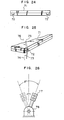
- FIG. 3 Various apparatus using a stationary multihead are also widely known.
- a compact cassette deck as shown in FIG. 3 is known, in which a stationary multihead M2 is used for two-way recording and reproduction.
- a magnetic tape T is driven in a direction as shown by the arrow A (the forward direction), and two recording and reproducing heads 21 and 22 of the multihead M2 record information on two recording tracks 5 1 and 5 2 respectively of the magnetic tape T.
- the magnetic tape T is driven in the other direction shown by the arrow B (the backward direction), and other two recording and reproducing heads 23 and 24 of the multihead M2 record information on two recording tracks 6 1 and 6 2 respectively of the magnetic tape T.
- two-way records are provided on the magnetic tape T.
- the recording and reproducing heads 21 and 22 scan the recording tracks 5 1 and 5 2 respectively-of the magnetic tape T driven in the direction A, and the recording and reproducing heads 23 and 24 scan the recording tracks 6 1 and 6 2 respectively of the magnetic tape T driven in the direction B.
- FIG. 4 there is a data recorder adapted for one-way recording and reproduction by a multihead M3 as shown in FIG. 4.
- the head gaps g of individual recording and reproducing heads 2 1 to 2 10 of the multihead M3 are oriented in the same direction, and the magnetization patterns 8 of records formed on recording tracks 5 1 to 5 10 of a magnetic tape T are also oriented in the same direction. Therefore, guard bands GB are similarly provided to separate the individual recording tracks.
- the width of the head gaps, equal to track's width, of the recording and reproducing heads has been made as small as possible, and, because of the minimized gap width, a considerable improvement in the recording density could be achieved.
- the guard bands GB had to be provided between the recording tracks TR, and the provision of such guard bands GB not contributing to the recording of information has given rise to the defect that the recording density is reduced by the amount corresponding to the areas occupied by the guard bands GB.
- Another object of the present invention is to provide a magnetic recording and reproducing apparatus in which an azimuth loss is positively utilized for the desired attainment of high-density recording and reproduction without making complex the structure of the magnetic recording and reproducing apparatus.
- Still another object of the present invention is to provide a magnetic recording and reproducing apparatus in which, besides the capability of high-density recording and reproduction utilizing the azimuth loss, the S/N ratio is not degraded by the presence of a tracking error.
- Yet another object of the present invention is to provide a magnetic recording and reproducing apparatus which is provided with a cassette-tape travelling direction identifying mechanism which identifies the travelling direction of a multitrack cassette tape thereby automatically orienting the head gaps of a multihead in the direction of correct inclination.
- a further object of the present invention is to. provide a magnetic recording and reproducing apparatus which can handle a magnetic tape having a large number of recording tracks so that the desired reduction of the transmission density per track in a PCM recorder using a stationary multihead can be satisfactorily achieved.
- FIG. 5 is a front elevation view of a multitrack recording and reproducing magnetic head MH employed in an embodiment of the magnetic recording and reproducing apparatus according to the present invention.
- the head gaps HG of the individual heads H make an angle of 8/2 with the axis X-X extending orthogonally with respect to the travelling direction of a magnetic tape, and the orientation of each of these head gaps HG is opposite to that of the adjacent ones.
- the magnetic head MH serving both of recording and reproduction of information is held stationary, and the information signal is recorded and/or reproduced only when the magnetic tape is driven in one way or in one direction.
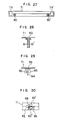
- FIG. 6 shows the state of data recorded on a magnetic tape T by the magnetic recording and reproducing head MH shown in FIG. 5.
- the data are recorded on eight recording tracks 5 1 to 5 8 of the magnetic tape T, and the recoridng angles 14 on the adjacent recording tracks have inclinations opposite to each other, each angle corresponding to the angle 8/2 shown in FIG. 5. Therefore, even if a tracking error may occur during reproduction from one of the tracks in the playback mode, the amount of crosstalk from the adjacent track can be made negligibly small by virtue of the azimuth loss which will be described later.
- the thickness of the shielding sheet 16 interposed between the individual heads H of the multihead MH can be made smaller than hitherto. It will be seen in FIG. 6 that a non-recorded portion 16' corresponding to the thickness of the shielding sheet 16 shown in FIG. 5 will be left although it occupies a very small proportion.
- Magnetic recording and reproducing heads MH as shown in FIGs. 7a and 7b are preferably used in order to eliminate such a non-recorded portion 16' and further increase or improve the recording density.
- FIGs. 7a and 7b shows the head gap arrangement in a magnetic head MH serving both of recording and reproduction, the magnetic head MH being held stationary relative to a magnetic tape which is driven for reciprocating movement without inverting, for example, a tape cassette, that is, without changing the widthwise upper and lower positions of the magnetic tape.
- the head gaps HG1 of heads H used exclusively for recording and reproduction when the magnetic tape is driven in the forward direction make an azimuth angle 8 with the corresponding head gaps HG2 of heads H used exclusively for recording and reproduction when the magnetic tape is driven in the backward direction (which heads will be referred to hereinafter as backward recording and reproducing heads).
- the array of the head gaps HG1 is so disposed relative to the array of the head gaps HG2 that the magnetization patterns formed by the former do not overlap those formed by the latter but adjoin each other. That is, these head gaps HG1 and HG2 are arranged in staggered relation.
- the head cores H of the head stack MH shown in FIG. 7a are arrayed in a direction orthogonal with respect to the travelling direction of the magnetic tape, and the alternate ones of the head gaps HG1 and HG2 are disposed in staggered relation or juxtaposed in zigzag fashion while defining the azimuth angle 8 therebetween.
- the alternate ones of the head gaps HG are also disposed in staggered relation but the head gap arrays providing the recording angle of ⁇ /2 are inclined in opposite directions relative to each other.
- the head gaps HG1 and HG2 are changed over in accordance with the running direction of the tape, by the head change-over means (not shown) for changing over the head electrically.
- FIG. 7c shows another form of the magnetic head MH.having similarly the staggered head gap arrangement.
- recording heads R and reproducing heads P are separately provided as shown.
- FIG. 9 shows another form of the magnetic head employed in another embodiment of the magnetic recording and reproducing apparatus according to the present invention.
- the same reference numerals are used to designate the same or like parts employed in the aforementioned embodiments.
- a magnetic tape T is driven in a direction as shown by the arrow A, and forward recording and reproducing heads 2 1 , 2 2 , Vietnamese, 2 9 of a stationary multihead MH record information on forward recording tracks 5 1 , 5 2 , ising, 5 9 respectively of the magnetic tape T. Then, when the magnetic tape T is driven in the opposite direction shown by the arrow B, backward recording and reproducing heads 2 1 ', 2 2 ', Vietnamese, 2 9 ' record information on backward recording tracks 6 1 , 6 2 , Vietnamese, 6 9 respectively of the magnetic tape T.
- the orientation of the head gaps g of the forward recording and reproducing heads 2 1 , 2 2 , Vietnamese, 2 9 makes an azimuth angle ⁇ with that of the head gaps g of the backward recording and reproducing heads 2 1 ', 2 2 ', Vietnamese, 2 9 '. Consequently, the direction of magnetization patterns 8A formed on the forward record- in g tracks 5 1 , 5 2 , Vietnamese, 5 9 differs from that of magnetization patterns 8B formed on the backward recording tracks 6 1 , 6 2 , Vietnamese, 6 9 .
- one of the recording tracks is different from that of the magnetization patterns formed on the adjacent recording track due to the fact that the forward recording tracks 5 1 , 5 23 Vietnamese, 59 and the backward recording tracks 6 1 , 6 2 , Vietnamese, 6 9 are arranged alternately in the widthwise direction of the magnetic tape T.
- the magnetic tape T is driven in the direction of the arrow A as in the forward record mode so as to scan the forward recoridng tracks 5 1 , 5 2 , Vietnamese, 5 9 by the forward recording and reproducing heads 2 1 , 2 2 , Vietnamese, 2 9 respectively, and the magnetic tape T is then driven in the direction of the arrow B so as to scan the backward recording tracks 6 1 , 6 2 , Vietnamese, 6 9 by the backward recording and reproducing heads 2 1 ', 2 2 ', Vietnamese, 2 9 ', thereby reproducing the recorded signal.
- the present invention utilizes such an azimuthal effect.
- the directions of the magnetization patterns 8A and 8B formed on the adjacent recording tracks are different from each other and are the same as the orientations of the head gaps of the recording and reproducing heads scanning such recording tracks respectively. Consequently, there there exists the azimuth angle 8 between the head gap of one of the recording and reproducing heads and the magnetization pattern formed on the recording track next. adjacent to the recording track scanned by the specific recording and reproducing head. Therefore, when the entirety of such an adjacent recording track is scanned by the specific recording and reproducing head, the level of the signal reproduced therefrom is attenuated due to the azimuth loss La expressed by the equation (1).
- the azimuth angle 8 is so selected that the level of the signal reproduced from such an adjacent recording track by the specific recording and reproducing head is always lower than a predetermined setting regardless of the proportion' of the width of the adjacent recording track scanned by the specific recording and reproducing head, whereby to - eliminate the necessity for provision of the guard band GB between the recording tracks adjoining each other.
- Such an azimuth angle 8 is determined in a-manner as will be described presently.
- the term in the equation (1) is expressed by and the azimuth loss La is calculated from the equation (1).
- the results are shown in FIG. 10.
- the width W of the recording track is 1 mm
- the travelling speed V of the magnetic tape is 19 cm/sec
- the lowest frequency f of the recording signal is 1 kHz.
- the azimuth angle ⁇ is calculated which can cause attenuation of 20 dB in the level of the signal reproduced from an adjacent recording track by one of the recording and reproducing heads shown in FIG. 9 due to a track displacement or a tracking error. That is, the azimuth angle ⁇ , which can provide such attenuation even when the repdoducing head gap of the head scans the full width W of the recording track adjacent to that to be scanned, is calculated from the equation (1).
- the attenuation of 20 dB can be caused without resorting to the azimuth loss La, since the value of 20 log 10 is equal to 20 dB in the equation (1). In such a case, therefore, the azimuth loss La need not be especially considered.
- the azimuth angle ⁇ is preferably so determined that the sum of the value of the azimuth loss La at a bottom of its curve in FIG. 10 and the amount of attenuation dependent upon the proportion of the width portion of the adjacent recording track scanned by the recording and reproducing head is more than 20 dB.
- the azimuth loss La of more than 20 dB is obtained even if .the recording and reproducing head scans the full width W of the adjacent recording track.
- attenuation of more than 20 dB can be caused regardless of the proportion of the width portion of the adjacent recording track scanned by the recording and reproducing head.
- Table 1 shows the value of the azimuth angle 8 satisfying various specific conditions.
- the present invention is applied to a multitrack PCM recorder using a compact cassette tape.
- the most suitable azimuth angle ⁇ in such a recorder will now be discussed.
- a data transmission rate as high as 1.5 - 2 Mbit/sec is generally required in view of the factors including the transmission signal bandwidth and the number of quantized bits.
- the data transmission rate is 1.7 M bit/sec when the transmission signal bandwidth is 20 kHz and the number of quantized bits is 14 and also when the synchronizing signal part and error correcting words are taken into consideration.
- the data transmission rate is 1.7 M bit/sec when the transmission signal bandwidth is 20 kHz and the number of quantized bits is 14 and also when the synchronizing signal part and error correcting words are taken into consideration.
- the number of tracks is selected to be 32 (16 tracks provided for each way and including 2 control tracks) and the minimum wavelength recorded per track is selected to be about 0.8 ⁇ m, when the factors including the feasibility of recording of wavelengths and the circuit cost are taken into consideration.
- the width of each track is 110 ⁇ m when the width of the non-recordable portion in each of the tape edge areas is supposed to be 145 ⁇ m.
- FIG. 11 shows the recording angle (azimuth angle) 8 and the amount of attenuation due to the azimuth loss La when a tracking error on a magnetic tape covers a width w which is 20 ⁇ m at the maximum.
- the solid curves in FIG. 11 indicate the amounts of attenuation due to the azimuth loss at 6 of 10°, 15°, 20° and 30° respectively, and the broken curves indicate the total amounts of attenuation each of which is the sum of the amount of attenuation indicated by the corresponding solid curve and the amount of attenuation of the reproduced signal level due to the decreased width of the track being reproduced. It will be seen in FIG.
- the most suitable value of the azimuth angle ⁇ must be selected taking into account the system mechanism and the required amount of attenuation.
- the S/N ratio of the system is slightly higher than 30 dB, and, therefore, the required amount of attenuation should be about 40 dB under a severer condition or at a recording wavelength of 1 ⁇ m.
- the angle ⁇ is preferably selected to be about 17° as seen in FIG. 11, and, when the spectrum at lower frequency is taken into account, the angle 8 of about 20° is most suitable.
- the azimuth angle ⁇ selected in the manner above described is based upon to determine the orientation of the gaps a of the recording and reproducing head MH shown in FIG. 9.
- the orientation of the gaps g of the recording and reproducing head MH may be selected as shown in FIGs. 12a and 12b.
- the adjoining recording and reproducing heads 2 1 and 2 1 ' of the multihead MH shown in FIG. 9 are merely shown for the purpose of illustration.
- FIG. 12a illustrates that the gap a of the forward recording and reproducing head 2 1 is oriented to be parallel to the widthwise direction of a magnetic tape, and the gap g of the backward recording and reproducing head 2 1 ' is oriented to make the azimuth angle ⁇ with the gap g of the head 2 1 .
- FIG. 12b illustrates that the gaps g of the recording and reproducing heads 21 and 2 1 ' make the same angle 1/2 8 with the widthwise direction of a magnetic tape respectively.
- the recording and reproducing heads 2 1 , 2 2 , ??, 2 9 and 2 1 ', 2 2 ', Vietnamese, 2 9 ' of the multihead.MH shown in FIG. 9 are longitudinally aligned on one line, it is not the essential requirement, and the forward recording and reproducing heads 2 1 , 2 2 , ...., 2 9 and the backward recording and reproducing heads 2 1 ', 2 2 ', Vietnamese, 2 9 ' may be arranged in a relation displaced or staggered toward the left and right sides in the longitudinal direction of the magnetic tape T as shown in FIG. 13.
- the head arrangement shown in FIG. 13 is advantageous in that the adjacent tracks can be easily brought into intimate contact with each other, improving the recording density.
- FIG. 14A is a perspective view to schematically . illustrate the head gap arrangement, in the case of two-way scanning and turing over the cassette, in still another embodiment of the present invention.
- a stationary forward recording and reproducing magnetic head MH1 includes head gaps g 1 , g 2 and g 3
- a stationary backward recording and reproducing magnetic head MH2 includes head gaps g l ', g 2 ' and g 3 '.
- the head MH1 and MH2 are electrically switched by the head change-over means (not shown) in accordance with the forward and backward in directions of the tape.
- FIG. 15 schematically shows the patterns . recorded on a magnetic tape T by the magnetic heads MH1 and MH2 shown in FIG. 14A.
- magnetization patterns 8 1 are formed on forward recording tracks 5 1 , 5 2 and 5 3 by the respective head gaps g 1 , g 2 and g 3
- magnetization patterns 8 2 are formed on backward recording tracks 6 1 , 6 2 and 6 3 by the head gaps g l ', g 2 ' and g 3 ' respectively.
- FIG. 1.4B Illustrates the head gap arrangement when each of the recording and reproducing magnetic heads MH1 and MH2 is replaced by three recording heads R and three reproducing heads P.
- the head gap, i.e. track width, of each of the reproducing heads P is selected to be wider than that of the corresponding recording head R as shown in FIGs. 20 to 22.
- the forward recording and reproducing magnetic head MH1 scans the forward recording tracks 5 1 , 5 2 and 5 3 for the purpose of reproduction
- the backward recording and reproducing magnetic head MH2 scans MH2 scans the backward recording tracks 6 1 , 6 2 and 6 3 for the purpose of reproduction.
- the head gap g 3 of the magnetic head MH1 scans the associated recording track 5 3 in a relation displaced by a distance d from the recording track 5 3 in the widthwise direction of the magnetic tape T as shown in FIG. 15. Since, in such a case, the head gap g 3 scans a portion d of the width of the adjacent recording track 6 3 , crosstalk from the recording track 6 3 occurs although the azimuth loss described already is present.
- the forward recording and reproducing magnetic head MH1 associated with the forward recording tracks 5 1 , 5 2 , 5 3 and the backward recording and reproducing magnetic head MH2 associated with the backward recording tracks 6 1 , 6 2 , 63 are essentially required.
- these magnetic heads MH1 and MH2 can serve both of recording and reproduction, it is necessary to amplify the signal reproduced from the individual recording tracks in order that the reproduced signal can be obtained without degradation of the S/N ratio, and, for this purpose, amplifiers are required for the individual head gaps of each of the magnetic heads MHl and MH2.
- a recording amplifier and a reproducing amplifier are required for each individual head gap, and this means that the number of required amplifiers is two times as large as the number of recording tracks.
- a change-over switch for changing over between each pair of the recording amplifier and the reproducing amplifier is additionally required, and the number of such switches is equal to the number of recording tracks, resulting in complexity of the structure of the apparatus. In order that the apparatus may not become complex in structure, it is desirable to provide a single multihead and means for causing rotating movement of the single multihead.
- FIG. 16A shows schematically the structure of one form of such magnetic head rotating means employed in an embodiment of the magnetic recording and reproducing apparatus according to the present invention.
- the rotating means includes a supporting member 45 supporting a single magnetic head MHl, a speed converter 46, a stepping motor 47 and a rotating direction controller 48.
- the single magnetic. head MH1 serves both of recording and reproduction, and a tape cassette containing a magnetic tape T is turned over or its widthwise upper and lower positions are changed in the backward record mode.
- FIGs. 17 and 18 schematically illustrate the magnetization patterns formed on recording tracks of a magnetic tape T by the magnetic head MH1 shown in FIGs. 16A.
- the same reference numerals are used to designate the same or similar parts or portions appearing in FIGs. 14 and 15.
- the magnetic head MH1 including the head gaps g l , g 2 and g 3 is supported on the supporting member 45, and this supporting member 45 can be rotated stepwise in either direction by the stepping motor 47 through the speed converter 46.
- the stepping motor 47 causes rotating movement of the magnetic head MH1 through an angle 6 1 with respect to the vertical axis X-X in one direction as shown by the arrow A or an angle e 2 in the other direction as shown by the arrow b.
- the magnetic tape T is driven in the forward direction shown by the arrow A in the attitude shown in FIG. 16A, but, when it is to be driven in the backward direction shown by the arrow B, its attitude is inverted with respect to the sheet of the drawing. That is, after the magnetic tape T has completed its forward travel, the magnetic tape T is removed and is re-mounted in a relation .changed in its widthwise upper and lower positions before it starts its backward travel.
- the cassette is turned over the change the travelling direction of the magnetic tape T. In other words, the edge of the magnetic tape T shown upper than the other in FIG.
- the magnetic tape T is driven in the same direction for example, the direction of the arrow A for both of forward travel and backward travel.
- the magnetic tape T is driven in the direction of the arrow A for forward travel and in the direction of the arrow B for backward travel.
- the magnetic head MH1 When the magnetic tape T is driven in the direction of the arrow A for forward travel, the magnetic head MH1 is rotated in the direction shown by the arrow a by the stepping motor 47, and, as a result, the head gaps g l , g 2 and g 3 are oriented in a direction X 1 which makes the angle 81 with the widthwise direction X-X of the magnetic tape T. Therefore, data are recorded on the forward recording tracks 5 1 , 5 2 and 5 3 of the magnetic tape T, and the direction of magnetization patterns 8 1 formed on the forward recording tracks 5 1 , 5 2 and 5 3 coincides with the direction X 1 inclined by ⁇ 1 relative to the widthwise direction X-X of the magnetic tape T as shown in FIG. 17.
- the individual head gaps g l , g 2 and g 3 are spaced apart from each other by the distance of their gap width, and these head gaps g l , g 2 and g 3 are disposed in the widthwise direction X-X of the magnetic tape T in such a relation that one of the edges of one of the head gaps or the head gap g 2 in this case registers with the longitudinal centerline 0-0' of the magnetic tape T. See the point 20 shown in FIG. 17.
- the magnetic tape T After the magnetic tape T has completed its forward travel, the magnetic tape T is removed and re-mounted to be now ready for backward travel as described hereinbefore.
- the head gaps g l , g 2 and g 3 are situated opposite to the non-recorded portions between the forward recording tracks 5 1 , 5 2 and 5 3 .
- the recording tracks having records provided thereon are displaced in the widthwise direction X-X of the magnetic tape T by the distance of the width of the recording tracks, that is, by the distance of the width of the head gaps relative to the head gaps g l , g 2 and g 3 .
- the magnetic head MH1 is then rotated through the angle ( ⁇ 1 + ⁇ 2 ) by the stepping motor 47 controlled by t he rotating direction controller 48, and the head gaps g 1 , g 2 and g 3 are now oriented in a direction X 2 which makes the angle ⁇ 2 , opposite to the angle ⁇ 1 , which the widthwise direction X-X of the magnetic tape T.
- the rotation angle ⁇ 2 of the magnetic head MH1 is equal to the rotation angle ⁇ 1 , the positions of the head gaps g l , g 2 and g 3 relative to the widthwise direction X-X of the magnetic tape T remain substantially unchanged regardless of the rotating movement of the magnetic head MH1.
- the recording and reproducing magnet ic head MH1 can serve the dual purpose of recording on the forward recording tracks and recording on the backward recording tracks.
- the width of records formed on the forward recording tracks 5 1 , 5 2 and 5 3 and that formed on the backward recording tracks 6 1 , 6 2 and 6 3 by recording in the presence of such an angular inequality are given by gcose ⁇ 1 and gcos ⁇ 2 respectively, where g is the width of the head gaps. Due to the relation ⁇ 1 ⁇ ⁇ 2 , the ratio between t he width of records formed on the forward recording tracks and that formed on t he backward recording tracks is given by cos ⁇ 1 /cos ⁇ 2 .
- the distances from the center of rotation 20 to the remotest end points of the head gaps g 1 , g 2 and g 3 are l 1 , l 2 and l 3 respectively, and ⁇ 1 > ⁇ 2 as shown in FIG. 17.
- the records formed on the forward recording tracks 5 1 and the backward reco recording tracks 6 2 , and similarly 5 3 and 6 1 , by recording by the head gaps g l , g 2 , g 3 overlap each other by the widths of
- the described change of the width of records formed on the recording tracks due to the inclination of the head gaps is only about 0.4% when the azimuth angle (8 1 + ⁇ 2 ) is selected to be about 5°. Further, the change of the width of records formed on the recording tracks depending on the head gap position on the magnetic tape T is only about 12 ⁇ m at the maximum. Such a value is allowable in practical use, when a 1/4-inch magnetic tape is used and the center of rotation 20 of the magnetic head MH1 is registered with the longitudinal centerline 0-0' of the magnetic tape T.
- the inclination 8 2 of the magnetic head MH1 relative to the line X-X should be selected to be equal to 6 1 .
- the magnetization patterns formed on the magnetic tape T will be as shown in FIG. 18. It will be seen in FIG. 18 that the magnetization patterns formed on the adjacent recording tracks are symmetrical with respect to the boundary line of these recording tracks. This means that the above-described change of the record width attributable to the reciprocation of the magnetic tape T cam be eliminated.
- a magnetic head of-the kind having three head gaps is employed. It is apparent, however, that a magnetic head having any other desired number of head gaps can be similarly effectively employed. It is also apparent that a magnetic head used exclusively for recording purpose and that used exclusively for reproducing purpose may be separately provided, and the orientation, or inclination, of the head gaps may be changed over depend ing on the travelling directions A and B of a magnetic tape.
- FIG. 16B In another form shown in FIG. 16B, recording and reproduction are performed by independent magnetic heads respectively and in the two-way scanning without inverting the cassette.
- a pair of reproducing heads MHF1 and MHF2 are disposed on both sides of a central recording head MHM and are held stationary, while the central recording head MHM is arranged to be rotatable as in the case of the head MH1 shown in FIG. 16A.
- This head MHM is rotatable and can be displaced by a distance equal to the track width in the direction of tape width, by head-shifting means (not shown).
- P of the reproducing heads MHF1 and MHF2 is selected to be larger than that of the head cores R of the recording head MHM.
- a single multihead MH1 includes recording heads R and reproducing heads P independent of each other. This multihead MH1 is rotated as in the case of the head MH1 shown in FIG. 16A.
- FIG. 19 shows the head gap arrangement employed in another embodiment of the apparatus according to the present invention.
- a stationary magnetic head MH3 used exclusively for recording purpose and a stationary magnetic head MH4 used exclusively for reproducing purpose are so disposed that the head gaps HG in the former and the corresponding head gaps HG in the latter are oriented to have the same angle of inclination, thereby attaining the effect similar to that exhibited by the magnetic heads MH1 and MH2 shown in FIG. 14B.
- a magnetic tape (not shown) is driven in one direction A and the other B as described already with reference to FIGs. 7a and 7b.
- crosstalk can be eliminated practically by the effect of the azimuth loss even if a tracking error occurs during tracking of a magnetic tape T.
- a tracking error d occurs, the level S of a reproduced signal is attenuated by the amount corresponding to the decreased track width (W - d).
- the reproduced signal level S is attenuated only slightly even in the presence of a slight tracking error d.
- the reproduced signal level S will be greatly attenuated or attenuated by 3 dB if the tracking error for the magnetic tape is as large as 30 ⁇ m.
- the prior art apparatus has therefore been defective in that the costs of its component parts are high, and the adjustment becomes complex.
- the reproducing head gap width is selected to be larger than the recording head gap width for improving the recording density without degrading the S/N ratio of the reproduced signal and without complicating the structure of the tape drive system, especially, that of the tracking error preventing mechanism.
- reference numerals 5 1 , 6 1 and 6 2 , 8 1 , 8 2 and 63 designate a forward recording track, backward recording tracks, magnetization patterns formed on the forward recording track 5 1 , magnetization patterns formed on the backward recording tracks 6 1 , 6 2 , and tracing patterns on a track being reproduced, respectively.
- the reproducing head gap width W' is selected to be larger by 2d than the recording head gap width W.
- the reproducing head gap width W' is now selected to be 140 ⁇ m when the recording head gap width W is 100 ⁇ m, and the allowance of the tracking error is set at ⁇ 20 ⁇ m.
- the positional relationship will be as shown in FIG. 20 in the absence of any tracking error.
- FIG. 21 illustrates that the tracking error increases up to its allowance limit of +20 ⁇ m.
- FIG. 22 illustrates that the tracking error exceeds its allowance limit and increases up to +40 ⁇ m.
- symbol d' designates the portion of the recording track 51 which is not traced during reproduction, and its value is 20 ⁇ m.
- Table 2 shows the S/N ratio in the various cases described above.
- T R and T P designate the recording head gap width and the reproducing head gap width respectively.
- the reproducing head gap width Tp can be determined on the basis of the allowance level of noise N relative to the track width and also on the basis of the width W of the recording track 5 1 interposed between the recording tracks 8 1 and 8 2 . Further, it is a common practice to employ a magnetic head of thin film type for the purpose of recording and .reproduction for such a multitrack magnetic tape by a single magnetic head, and the use of such a head is advantageous in that the printing pattern may merely be modified to change the head gap width.
- the reproducing head gap width Tp may be selected to be smaller than the recording head gap width T R- as shown in FIG. 23.
- the recording density on a multitrack magnetic tape can be increased or improved without complicating the structure of the tape drive system.
- the larger the tracking error the rate of degradation of the S/N ratio becomes less. This means that there is no necessity to use an expensive mechanism for the prevention of the tracking error.
- the present invention since the present invention has the arrangement that the recording angle is made to be different in accordance with the travelling direction of the tape, it is necessary to identify the travelling direction of the tape by any means.
- FIGs. 24 to 30 show various forms of means for automatically identifying the travelling direction of a magnetic tape, preferably employed in the magnetic recording and reproducing apparatus of the present invention adapted for recording and reproduction by driving the magnetic tape in the forward and backward directions.
- FIG. 24 is. a side elevation view of a cassette casing containing a magnetic tape, employed in another embodiment of the present invention.
- FIG. 25 shows the structure of a mechanism for automatically identifying the travelling direction of the magnetic tape contained in the cassette casing shown in FIG. 24.
- a pair of spaced openings 72 and 72' used for tape direction identification are provided in the back wall of the cassette casing 71.
- the travelling direction of the cassette tape is determined by the direction of insertion of the cassette casing 71 into a stereo recorder. Therefore, : in the form shown in FIG. 24, the openings 72 and 72' used for tape direction identification are provided, in one of the halves of the back wall of the cassette casing 71 divided in the thicknesswise direction.
- the stereo cassette recorder is provided, as shown in FIG. 25, with a pair of fingers 73 and 75 for detecting the position of one of the openings 72 and 72' shown in FIG. 24.
- FIG. 25 shows the mounted state of the cassette tape.
- T he fingers 73 and 75 are made of, for example, a resilient electrical conductive metal and are disposed in such a position that the free end of one of the fingers 73 and 75 engages with one of the opens 72 and 72' when such an opening is present at that position.
- FIG. 25 illustrates that the lower finger 73 engages with and resiliently advances into the opening 72. By engagement of the finger 73 with the opening 72, a switch 74 is turned on.
- the orientation of the head gaps of the magnetic head in the stereo recorder is changed in one of the two predetermined directions.
- a head inclination change-over unit 78 is energized so as to change the inclination of a head stack 77 constituting the stereo recording and reproducing head, as shown in FIG. 26.
- the other:finger 75 is urged by the cassette casing 71 in a direction in which another switch 76 is maintained in its off position.
- FIG. 27 showing another form of the identifying means employed in the present invention, a pair of spaced mal-erasing prevention openings 79 for preventing mal-erasing of records are provided in the back wall of a casette casing 71.
- the cassette casing 71 is provided with a pair of spaced means 80 and 80' used for tape direction identification.
- Such means 80 and 80' may be openings similar to those shown in FIG. 24 or may be conductor coatings or conductive strips exhibiting the effect similar to that exhibited in FIG. 24.
- FIG. 28 shows a tape direction identification mechanism employed when the conductive strips are used as the means 80 and 80' provided for tape direction identification.
- a pair of contacts 81 and 81' made of a resilient electrical conductor are provided in the positions of the respective fingers 73 and 75 shown in FIG. 25 to replace the latter.
- the contacts 81 and 81' engage with the conductive strip 80, and a current path through the conductive strip 80'and contacts 81, 81' is established to energize the head inclination.
- FIG. 29 showing still another form of the identifying means employed in the present invention, a light reflector or a light absorber is employed to replace each of the tape direction identifying means 80 and 80'.
- reference numerals 71, 82, 83, 84 and 85 designate a cassette casing, a light source such as a light emitting diode, a light sensor such as a photo diode, a light shielding screen, and a strip of light reflecting or absorbing material used for identifying the travelling direction of a magnetic tape, respectively.
- the light reflecting or absorbing strip 85 is disposed at a position similar to the disposed position of the means 80 shown in FIG. 27.
- the light source 82, the light sensor 83 and the shielding screen 84 shown in FIG.. 29 are disposed in a stereo recorder at such positions that, when the cassette casing 71 containing a magnetic tape is mounted in the stereo recorder, the light reflecting or absorbing strip 85 provided on the cassette casing 71 is opposed by the light source 82, light sensor 83 and shielding screen 84.
- FIG. 30 shows in more detail the practical structure of the tape direction identification mechanism shown in FIG. 29.
- the light source 82 is disposed opposite to the central area of the back wall of the cassette casing 71
- the light sensor 83 is composed of a pair of light sensing elements 83' and 83" disposed opposite to the upper and lower halves respectively of the back wall of the cassette casing 71 divided in the thicknesswise direction.
- the light source 82 and the light sensing elements 83' and 83" are so arranged that they are isolated from each other by the light shielding screen 84 of T shape.
- the head inclinination change-over unit 78 controlling the inclination of the head stack 77 shown in FIG. 26 is energized to incline the head gaps of the magnetic head in one of the predetermined directions corresponding to the travelling direction of the magnetic tape.
- the magnetic recording and reproducing apparatus of the present invention adapted for recording and reproduction using a multitrack cassette tape driven in the forward and backward directions comprises means used for identifying the travelling direction of the cassette tape and provided on one of the outer walls of the cassette casing, and means or detecting the above means provided on the cassette casing thereby identifying the travelling direction of the cassette tape when the cassette casing is mounted in the magnetic recording and reproducing apparatus.
- the control output from the tape direction identifying mechanism is utilized to automatically incline the head gaps of the magnetic head in one of the predetermined directions so that records provided on. a recording track by the'azimuth recording technique can be accurately reproduced in the playback mode. Therefore, the present invention can reliably prevent failure of reproduction due to miss-detection of the tape travelling direction or accidental erasion of records due to a mistake of recognizing a recorded tape as a non-recorded tape.
Abstract
Description
- This invention relates to an azimuthal magnetic recording and reproducing apparatus in which each of a plurality of recording tracks extending in the longitudinal direction of a magnetic tape is magnetized in a direction different from that of the adjacent one so that an information signal can be recorded on the recording tape in a high recording density and can then be reproduced therefrom.
- In a recorder such as a tape recorder or a data recorder using a magnetic tape, the technique is commonly known according to which an information signal is recorded on and reproduced from a plurality of tracks arranged in parallel to each other in the widthwise direction of the magnetic tape, that is, in the direction orthogonal with respect to the travelling direction of the magnetic tape. Because of such a manner of recording and reproduction, the magnetic tape is driven in the forward and backward directions or is driven once in one direction or is repeatedly driven in one direction only, and a magnetic head having a very small width is used for the purpose of recording and reproduction. The magnetic head used for this purpose has a single head gap or a plurality of head gaps. When the magnetic head having the single head gap is used, the magnetic head is moved in the widthwise direction of the magnetic tape each time the magnetic tape has been driven in a predetermined direction. On the other hand, when the magnetic head having the plural head gaps is used, the operating head gaps are sequentially electrically switched over each time the magnetic tape has been driven in the forward and backward directions. The magnetic head of the type in which the head gaps are sequentially electrically switched over is superior in the structural aspect to the magnetic head of the single head gap type, since the former does not require complex means for displacing or moving the magnetic head relative to the magnetic tape.
- A prior art magnetic head having such a plurality of head gaps will be described in further detail.
- FIG. 1 is a perspective view of such a prior art magnetic head used for two-way recording and reproduction. Referring to FIG. 1, the
magnetic head 1 is shown to include twohead gaps head gaps 21' and 22 T to be used for backward scanning and is supported on ahead support 3. - FIG. 2 shows schematically patterns recorded on a magnetic tape T by the
magnetic head 1 shown in FIG. 1. Referring to FIG. 2, the magnetic tape T includes recording tracks 51 and 52 recorded with information during the travel of the magnetic tape T in the forward direction (which tracks will be referred to hereinafter as forward recording tracks), recording tracks 61 and 62 recorded with information during the travel of the magnetic tape T in the backward direction (which tracks will be referred to hereinafter as backward recording tracks), and guard bands GB separating the tracks 51, 52, 61 and 62. Thenumeral 8 designates magnetization patterns formed on these recording tracks. - The operation of the prior art magnetic head will now be described.
- In FIG. 2, the magnetic tape T is driven in a direction as shown by the arrow A for its forward travel, and the
head gaps magnetic head 1 are selected to record information on the forward recording tracks 51 and 52 respectively. After recording of information by the forward travel of the magnetic tape T, the travelling direction is reversed to a direction as shown by the arrow B, and head gaps 21' and 22' of themagnetic head 1 are now selected by a head change-over means (not shown) for changing over the heads electrically. The head gaps 21' and 22' of themagnetic head 1 record information on the backward recording tracks 61 and 62 respectively of the magnetic tape T. - In this manner, two-way recording is done on the magnetic tape T. In the playback mode, the forward recording and reproducing
head gaps magnetic head 1 may merely have the two recording and reproducinghead gaps magnetic head 1 may be moved in the widthwise direction of the magnetic tape T depending on whether the magnetic tape T is driven in the forward direction or backward direction, so as to record and reproduce information on and from the recording tracks 51 and 52 or 61 and 6 2. - Recording on the recording tracks 61 and 62 described above may also be done by, for example, inverting the tape cassette containing the magnetic tape, that is, by turning over the cassette.
- The
head gaps magnetic head 1 extend in the same direction or vertical direction in FIG. 1, and, because of the extending direction of thehead gaps magnetization patterns 8 formed on the recording tracks 513 52, 61 and 62, hence, the direction of magnetization orthogonal with respect to the recording tracks is the same. Therefore, when the recording tracks are close relative to each other, and a so-called tracking error occurs in the playback mode, reproduction of information from one of the recording tracks may be encountered with the problem of crosstalk due to partial reproduction of information from the adjacent one of the recording tracks. Therefore, the guard bands GB, which are the regions carrying no records, are provided between the individual recording tracks so that crosstalk as described above may not occur. - Various apparatus using a stationary multihead are also widely known. As an example, a compact cassette deck as shown in FIG. 3 is known, in which a stationary multihead M2 is used for two-way recording and reproduction. Referring to FIG. 3, a magnetic tape T is driven in a direction as shown by the arrow A (the forward direction), and two recording and reproducing
heads heads heads heads - In the magnetic head structure shown in FIG. 3 too, the problem of crosstalk as described above is also inevitable due to the same orientation of the head gaps g, and guard bands GB are similarly required.
- As another prior'art example, there is a data recorder adapted for one-way recording and reproduction by a multihead M3 as shown in FIG. 4. In this case too, the head gaps g of individual recording and reproducing
heads 21 to 210 of the multihead M3 are oriented in the same direction, and themagnetization patterns 8 of records formed on recording tracks 51 to 510 of a magnetic tape T are also oriented in the same direction. Therefore, guard bands GB are similarly provided to separate the individual recording tracks. - In a prior art magnetic recording and reproducing apparatus using a multihead, the width of the head gaps, equal to track's width, of the recording and reproducing heads has been made as small as possible, and, because of the minimized gap width, a considerable improvement in the recording density could be achieved. However, as described with reference to FIGs. 2 to 4, the guard bands GB had to be provided between the recording tracks TR, and the provision of such guard bands GB not contributing to the recording of information has given rise to the defect that the recording density is reduced by the amount corresponding to the areas occupied by the guard bands GB.
- It is therefore an object of the present invention to provide a novel and improved magnetic recording and reproducing apparatus in which anazimuth angle is provided between the magnetization patterns of records formed on adjacent recording tracks of a magnetic tape so as to minimize the possibility of crosstalk of infor-. mation between such tracks.
- Another object of the present invention is to provide a magnetic recording and reproducing apparatus in which an azimuth loss is positively utilized for the desired attainment of high-density recording and reproduction without making complex the structure of the magnetic recording and reproducing apparatus.
- Still another object of the present invention is to provide a magnetic recording and reproducing apparatus in which, besides the capability of high-density recording and reproduction utilizing the azimuth loss, the S/N ratio is not degraded by the presence of a tracking error.
- Yet another object of the present invention is to provide a magnetic recording and reproducing apparatus which is provided with a cassette-tape travelling direction identifying mechanism which identifies the travelling direction of a multitrack cassette tape thereby automatically orienting the head gaps of a multihead in the direction of correct inclination.
- A further object of the present invention is to. provide a magnetic recording and reproducing apparatus which can handle a magnetic tape having a large number of recording tracks so that the desired reduction of the transmission density per track in a PCM recorder using a stationary multihead can be satisfactorily achieved.
- FIG. 1 is a perspective view of a prior art magnetic head used for multitrack recording on a magnetic tape.
- FIG. 2 is a plan view of a magnetic tape to schematically illustrate the patterns of records magnetically formed by two-way recording with the magnetic head shown in FIG. 1.
- FIG. 3 shows schematically the head gap arrangement in a prior art magnetic recording and reproducing head and shows also the patterns magnetically recorded on a magnetic tape by such a magnetic head.
- FIG. 4 shows schematically the head gap arrangement in a prior art magnetic head of multihead type and shows also the patterns magnetically recorded on a magnetic tape by such a magnetic head.
- FIG. 5 is a front elevation view to illustrate schematically the head gap arrangement in one form of the magnetic head employed in an embodiment of the apparatus according to the present invention.
- FIG. 6 is a front elevation view to illustrate schematically the patterns of records magnetically formed on a magnetic tape by the magnetic head shown in FIG. 5.
- FIGs. 7a and 7b are front elevation views to illustrate schematically the head gap arrangement in other forms respectively of the magnetic head of multihead type employed in other embodiments of the apparatus according to the present invention, in each of which the magnetic head is held stationary and a magnetic tape contained in, for example;'a tape cassette is driven in one direction and the other without turning over the tape cassette.
- FIG. 7c is a schematic front elevation view of another form of the multihead employed in the present invention, in which each of the recording and reproducing heads shown in FIG. 7a is replaced by a pair of a recording head and a reproducing head.
- FIG. 8 is a front elevation view to illustrate schematically the patterns of records magnetically formed on a magnetic -tape by the magnetic head shown in FIG. 7a, 7b or 7c.
- FIG. 9 is a front elevation view to illustrate schematically the head gap arrangement in still another form of the magnetic head employed in another embodiment of the apparatus according to the present invention and to illustrate also the patterns of records magnetically formed on a magnetic tape by such a magnetic head.
- FIG. 10 is a graph illustrating the azimuth loss in the embodiment of the present invention shown in, for example, FIG. 9.
- FIG. 11 is a graph illustrating the azimuth loss and MFM spectrum in an embodiment of the present invention.
- FIGs. 12a, 12b and 13 are front elevation views to schematically illustrate the head gap arrangement other forms of the magnetic head employed in other embodiments of the apparatus according to the present invention.
- FIG. 14A is a perspective view to schematically illustrate the head gap arrangement in still another form of the magnetic head employed in another embodiment of the apparatus according to the present invention.
- FIG. 14B is a front elevation view to schematically illustrate the head gap arrangement when each of the recording and reproducing heads shown in FIG. 14A is replaced by a pair of a recording head and a reproducing head.
- FIG. 15 is a front elevation view to schematically illustrate the patterns of records magnetically formed on a magnetic tape by the magnetic head shown in FIG. 14A.
- FIG. -16A is a perspective view showing one form of magnetic head rotating means suitable for use in an embodiment of the apparatus of the present invention.
- FIG. 16B is a front elevation view to illustrate schematically the head gap arrangement when the recording and reproducing head shown in FIG. 16A is replaced by a recording head and two reproducing heads.
- FIG. 16C is a front elevation view to schematically illustrate the head gap arrangement when the recording and reproducing head shown in FIG. 16A is divided into a recording head and a reproducing head.
- FIGs. 17 and 18 are front elevation views to schematically illustrate the patterns of records magnetically formed by the magnetic head shown in FIG. 16A.
- FIG. 19 is a front elevation view to schematically illustrate the head gap arrangement in another form of the magnetic head employed in another embodiment of the apparatus according to the present invention.
- FIGs. 20 to 23 show schematically the magnetically formed patterns for illustrating the S/N ratio of a reproduced signal when the redproducing track width is not equal to the recording track width.
- FIGs. 24 and 25 are a side elevation view and a perspective view respectively of one form of means employed in an embodiment of the present invention for automatically identifying the travelling direction of a magnetic tape.
- FIG. 26 is a front elevation view of one form of magnetic head inclination change-over means preferably employed in the present invention for establishing the azimuth angle of the head gaps of the magnetic head.
- FIGs. 27 and 28 are side elevation views of other forms respectively of the means for automatically identifying the travelling direction of a magnetic tape.
- FIGs. 29 and 30 are a plan view and a side elevation view respectively.of another form of the means for automatically identifying the travelling direction of a magnetic tape.
- Referring now to the drawings, FIG. 5 is a front elevation view of a multitrack recording and reproducing magnetic head MH employed in an embodiment of the magnetic recording and reproducing apparatus according to the present invention. As shown in-FIG. 5, the head gaps HG of the individual heads H make an angle of 8/2 with the axis X-X extending orthogonally with respect to the travelling direction of a magnetic tape, and the orientation of each of these head gaps HG is opposite to that of the adjacent ones. In this embodiment, the magnetic head MH serving both of recording and reproduction of information is held stationary, and the information signal is recorded and/or reproduced only when the magnetic tape is driven in one way or in one direction.
- FIG. 6 shows the state of data recorded on a magnetic tape T by the magnetic recording and reproducing head MH shown in FIG. 5. As shown in FIG. 6, the data are recorded on eight recording tracks 51 to 58 of the magnetic tape T, and the recoridng angles 14 on the adjacent recording tracks have inclinations opposite to each other, each angle corresponding to the
angle 8/2 shown in FIG. 5. Therefore, even if a tracking error may occur during reproduction from one of the tracks in the playback mode, the amount of crosstalk from the adjacent track can be made negligibly small by virtue of the azimuth loss which will be described later. - Since thus the provision of the azimuth angle 6 between the adjacent head gaps HG of the heads H can make the adverse effect of crosstalk negligible even if a tracking error occurs in the playback mode, the thickness of the shielding
sheet 16 interposed between the individual heads H of the multihead MH can be made smaller than hitherto. It will be seen in FIG. 6 that a non-recorded portion 16' corresponding to the thickness of the shieldingsheet 16 shown in FIG. 5 will be left although it occupies a very small proportion. - Magnetic recording and reproducing heads MH as shown in FIGs. 7a and 7b are preferably used in order to eliminate such a non-recorded portion 16' and further increase or improve the recording density.
- Each of FIGs. 7a and 7b shows the head gap arrangement in a magnetic head MH serving both of recording and reproduction, the magnetic head MH being held stationary relative to a magnetic tape which is driven for reciprocating movement without inverting, for example, a tape cassette, that is, without changing the widthwise upper and lower positions of the magnetic tape. In each of the magnetic heads MH shown in FIGs. 7a and 7b, the head gaps HG1 of heads H used exclusively for recording and reproduction when the magnetic tape is driven in the forward direction (which heads will be referred to hereinafter as forward recording and reproducing heads) make an
azimuth angle 8 with the corresponding head gaps HG2 of heads H used exclusively for recording and reproduction when the magnetic tape is driven in the backward direction (which heads will be referred to hereinafter as backward recording and reproducing heads). It will be also seen in FIGs. 7a and 7b that the array of the head gaps HG1 is so disposed relative to the array of the head gaps HG2 that the magnetization patterns formed by the former do not overlap those formed by the latter but adjoin each other. That is, these head gaps HG1 and HG2 are arranged in staggered relation. - Describing in further detail, the head cores H of the head stack MH shown in FIG. 7a are arrayed in a direction orthogonal with respect to the travelling direction of the magnetic tape, and the alternate ones of the head gaps HG1 and HG2 are disposed in staggered relation or juxtaposed in zigzag fashion while defining the
azimuth angle 8 therebetween. In the case of the head stack MH shown in FIG. 7b, the alternate ones of the head gaps HG are also disposed in staggered relation but the head gap arrays providing the recording angle of θ/2 are inclined in opposite directions relative to each other. The head gaps HG1 and HG2 are changed over in accordance with the running direction of the tape, by the head change-over means (not shown) for changing over the head electrically. - FIG. 7c shows another form of the magnetic head MH.having similarly the staggered head gap arrangement. In FIG. 7C, however, recording heads R and reproducing heads P are separately provided as shown.
- By the use of the magnetic heads MH shown in FIGs. 7a, 7b and 7c, data can be recorded on a magnetic tape T without producing any non-recorded portions on the magnetic tape T as shown in FIG. 8.
- FIG. 9 shows another form of the magnetic head employed in another embodiment of the magnetic recording and reproducing apparatus according to the present invention. In FIG. 9, the same reference numerals are used to designate the same or like parts employed in the aforementioned embodiments.
- Referring to FIG. 9, a magnetic tape T is driven in a direction as shown by the arrow A, and forward recording and reproducing
heads - As seen in FIG. 9, the orientation of the head gaps g of the forward recording and reproducing
heads magnetization patterns 8A formed on the forward record- ing tracks 51, 52, ....., 59 differs from that ofmagnetization patterns 8B formed on the backward recording tracks 61, 62, ....., 69. The direction of the magnetization patterns formed on. one of the recording tracks is different from that of the magnetization patterns formed on the adjacent recording track due to the fact that the forward recording tracks 51, 523 ....., 59 and the backward recording tracks 61, 62, ....., 6 9 are arranged alternately in the widthwise direction of the magnetic tape T. - In the playback mode, the magnetic tape T is driven in the direction of the arrow A as in the forward record mode so as to scan the forward recoridng tracks 51, 52, ....., 59 by the forward recording and reproducing
heads - When the direction of a magneticzation pattern formed on a recordng track of a magnetic tape makes an
azimuth angle 8 with the orientation of a head gap of a reproducing head, it is known that an azimuth loss La expressed by the following equation appears in the reproduced signal:

- The present invention utilizes such an azimuthal effect. As described already with reference to FIG. 9, the directions of the
magnetization patterns azimuth angle 8 between the head gap of one of the recording and reproducing heads and the magnetization pattern formed on the recording track next. adjacent to the recording track scanned by the specific recording and reproducing head. Therefore, when the entirety of such an adjacent recording track is scanned by the specific recording and reproducing head, the level of the signal reproduced therefrom is attenuated due to the azimuth loss La expressed by the equation (1). According to the present invention, theazimuth angle 8 is so selected that the level of the signal reproduced from such an adjacent recording track by the specific recording and reproducing head is always lower than a predetermined setting regardless of the proportion' of the width of the adjacent recording track scanned by the specific recording and reproducing head, whereby to - eliminate the necessity for provision of the guard band GB between the recording tracks adjoining each other. - Such an
azimuth angle 8 is determined in a-manner as will be described presently. - Now, the term


- Under such conditions, the azimuth angle θ is calculated which can cause attenuation of 20 dB in the level of the signal reproduced from an adjacent recording track by one of the recording and reproducing heads shown in FIG. 9 due to a track displacement or a tracking error. That is, the azimuth angle θ, which can provide such attenuation even when the repdoducing head gap of the head scans the full width W of the recording track adjacent to that to be scanned, is calculated from the equation (1). When the specific recording and reproducing head scans the adjacent recording track over a width portion which is, for example, 1/10 of the full width W of the adjacent recording track, the attenuation of 20 dB can be caused without resorting to the azimuth loss La, since the value of 20 log10

- Referring to FIG. 10 again, the relation between the azimuth loss La and the amount of attenuation dependent upon the proportion of the width portionof the adjacent track scanned by the specific recording and reproducing head will now be considered. The azimuth angle θ is preferably so determined that the sum of the value of the azimuth loss La at a bottom of its curve in FIG. 10 and the amount of attenuation dependent upon the proportion of the width portion of the adjacent recording track scanned by the recording and reproducing head is more than 20 dB. When, the value of x is selected to be, for example, x = 3.47 in FIG. 10, the azimuth loss La of more than 20 dB is obtained even if .the recording and reproducing head scans the full width W of the adjacent recording track. Thus, attenuation of more than 20 dB can be caused regardless of the proportion of the width portion of the adjacent recording track scanned by the recording and reproducing head.
- The
azimuth angle 8 is therefore calculated to be θ = 33.5° from the value of x given by

- The above description refers merely to one example of the manner of determination of the azimuth angle θ, and it is apparent that the azimuth angle θ can be suitably selected to meet specific conditions selected.
- Table 1 shows the value of the
azimuth angle 8 satisfying various specific conditions.
- As another embodiment, the present invention is applied to a multitrack PCM recorder using a compact cassette tape. The most suitable azimuth angle θ in such a recorder will now be discussed.
- In such a PCM recorder, a data transmission rate as high as 1.5 - 2 Mbit/sec is generally required in view of the factors including the transmission signal bandwidth and the number of quantized bits. For example, the data transmission rate is 1.7 M bit/sec when the transmission signal bandwidth is 20 kHz and the number of quantized bits is 14 and also when the synchronizing signal part and error correcting words are taken into consideration. For the purpose of recording such information on a compact cassette tape which has a width of 3.81 mm and travels at a speed of 4.75 cm/sec, it is. most preferable that the number of tracks is selected to be 32 (16 tracks provided for each way and including 2 control tracks) and the minimum wavelength recorded per track is selected to be about 0.8 µm, when the factors including the feasibility of recording of wavelengths and the circuit cost are taken into consideration. In such a tape, the width of each track is 110 µm when the width of the non-recordable portion in each of the tape edge areas is supposed to be 145 µm.
- In the PCM recorder which is a digital recorder, low-frequency components are present in slight proportions only. Further, when a modulation method such as an MFM (modified frequency modulation) method is employed in such a recorder, the peak value of frequency components does not appear at the lowest recording wavelength but appears in the vicinity of a recording wavelength of 1 µm or a recording frequency of 50 kHz.
- FIG. 11 shows the recording angle (azimuth angle) 8 and the amount of attenuation due to the azimuth loss La when a tracking error on a magnetic tape covers a width w which is 20 µm at the maximum. The solid curves in FIG. 11 indicate the amounts of attenuation due to the azimuth loss at 6 of 10°, 15°, 20° and 30° respectively, and the broken curves indicate the total amounts of attenuation each of which is the sum of the amount of attenuation indicated by the corresponding solid curve and the amount of attenuation of the reproduced signal level due to the decreased width of the track being reproduced. It will be seen in FIG. 11 that, although the amount of attenuation increases with the increase in the recording angle (azimuth angle) θ, the rate of attenuation decreases. Therefore, the most suitable value of the azimuth angle θ must be selected taking into account the system mechanism and the required amount of attenuation.
- The S/N ratio of the system is slightly higher than 30 dB, and, therefore, the required amount of attenuation should be about 40 dB under a severer condition or at a recording wavelength of 1 µm. Accordingly, the angle θ is preferably selected to be about 17° as seen in FIG. 11, and, when the spectrum at lower frequency is taken into account, the
angle 8 of about 20° is most suitable. In FIG. 11, the frequency spectrum of the MFM signal at θ = 20° is shown, by way of example. It will be seen in FIG. 11 that attenuation of -38 dB to -58 dB can be attained throughout the bandwidth of MFM modulation. - The azimuth angle θ selected in the manner above described is based upon to determine the orientation of the gaps a of the recording and reproducing head MH shown in FIG. 9. The orientation of the gaps g of the recording and reproducing head MH may be selected as shown in FIGs. 12a and 12b. In FIGs. 12a and 12b, the adjoining recording and reproducing
heads 21 and 21' of the multihead MH shown in FIG. 9 are merely shown for the purpose of illustration. FIG. 12a illustrates that the gap a of the forward recording and reproducinghead 21 is oriented to be parallel to the widthwise direction of a magnetic tape, and the gap g of the backward recording and reproducing head 21' is oriented to make the azimuth angle θ with the gap g of thehead 21. FIG. 12b illustrates that the gaps g of the recording and reproducingheads 21 and 21' make thesame angle 1/2 8 with the widthwise direction of a magnetic tape respectively. - Although all of the recording and reproducing
heads heads - FIG. 14A is a perspective view to schematically . illustrate the head gap arrangement, in the case of two-way scanning and turing over the cassette, in still another embodiment of the present invention. Referring to FIG. 14A, a stationary forward recording and reproducing magnetic head MH1 includes head gaps g1, g 2 and g3, and a stationary backward recording and reproducing magnetic head MH2 includes head gaps gl', g2' and g3'. The head MH1 and MH2 are electrically switched by the head change-over means (not shown) in accordance with the forward and backward in directions of the tape.
- FIG. 15 schematically shows the patterns . recorded on a magnetic tape T by the magnetic heads MH1 and MH2 shown in FIG. 14A. Referring to FIG. 15,
magnetization patterns 81 are formed on forward recording tracks 51, 52 and 53 by the respective head gaps g1, g 2 and g3, andmagnetization patterns 82 are formed on backward recording tracks 61, 62 and 63 by the head gaps g l', g2' and g3' respectively. - FIG. 1.4B'illustrates the head gap arrangement when each of the recording and reproducing magnetic heads MH1 and MH2 is replaced by three recording heads R and three reproducing heads P. In this head gap arrangement, the head gap, i.e. track width, of each of the reproducing heads P is selected to be wider than that of the corresponding recording head R as shown in FIGs. 20 to 22.
- In the playback mode scanning the magnetic tape T recorded with information in the manner described with reference to FIG. 15, the forward recording and reproducing magnetic head MH1 scans the forward recording tracks 51, 52 and 53 for the purpose of reproduction, and the backward recording and reproducing magnetic head MH2 scans MH2 scans the backward recording tracks 61, 62 and 63 for the purpose of reproduction. It is supposed now that the head gap g3 of the magnetic head MH1 scans the associated recording track 53 in a relation displaced by a distance d from the recording track 53 in the widthwise direction of the magnetic tape T as shown in FIG. 15. Since, in such a case, the head gap g3 scans a portion d of the width of the adjacent recording track 63, crosstalk from the recording track 63 occurs although the azimuth loss described already is present.
- Let S be the level of the signal reproduced from the specific recording track 53, D the level of the signal reproduced from the adjacent recording track 63, W the width of these recording tracks, and λ the wavelength of the recording signal. Then, the amount of crosstalk D/S is expressed by the following equation:

- Suppose that the directions of the magnetization patterns formed on these two adjoining tracks are the same. Then, the angle θ = 0 in the equation (3), and the amount of crosstalk D/S is now expressed as
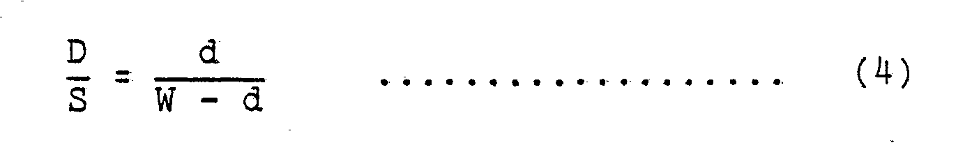
- It will be apparent from comparison between the equations (3) and (4) that the amount of crosstalk given by the equation (3) is smaller than that given by the equation (4) when θ ≠ 0.
- It will thus be seen that, when the directions of magnetization patterns formed on two adjoining recording tracks are not the same but are different from each other, crosstalk from one of the recording tracks can be sufficiently reduced by the azimuth loss regardless of relative displacement of the head gap, scanning the other recording track, toward the former recording track.
- However, in the form shown in FIG. 14A, the forward recording and reproducing magnetic head MH1 associated with the forward recording tracks 51, 52, 53 and the backward recording and reproducing magnetic head MH2 associated with the
backward recording tracks 61, 62, 63 are essentially required. Although these magnetic heads MH1 and MH2 can serve both of recording and reproduction, it is necessary to amplify the signal reproduced from the individual recording tracks in order that the reproduced signal can be obtained without degradation of the S/N ratio, and, for this purpose, amplifiers are required for the individual head gaps of each of the magnetic heads MHl and MH2. - More precisely, a recording amplifier and a reproducing amplifier are required for each individual head gap, and this means that the number of required amplifiers is two times as large as the number of recording tracks. Also, a change-over switch for changing over between each pair of the recording amplifier and the reproducing amplifier is additionally required, and the number of such switches is equal to the number of recording tracks, resulting in complexity of the structure of the apparatus. In order that the apparatus may not become complex in structure, it is desirable to provide a single multihead and means for causing rotating movement of the single multihead.
- FIG. 16A shows schematically the structure of one form of such magnetic head rotating means employed in an embodiment of the magnetic recording and reproducing apparatus according to the present invention. Referring to FIG. 16A, the rotating means includes a supporting
member 45 supporting a single magnetic head MHl, aspeed converter 46, a steppingmotor 47 and arotating direction controller 48. In the illustrated embodiment of the magnetic recording and reproducing apparatus of the present invention, the single magnetic. head MH1 serves both of recording and reproduction, and a tape cassette containing a magnetic tape T is turned over or its widthwise upper and lower positions are changed in the backward record mode. - FIGs. 17 and 18 schematically illustrate the magnetization patterns formed on recording tracks of a magnetic tape T by the magnetic head MH1 shown in FIGs. 16A. In FIGs. 16A, 17 and 18, the same reference numerals are used to designate the same or similar parts or portions appearing in FIGs. 14 and 15.
- The operation of this embodiment will now be described with reference to FIGs. 16A, 17 and 18.
- Referring first to FIG. 16A, the magnetic head MH1 including the head gaps gl, g2 and g3 is supported on the supporting
member 45, and this supportingmember 45 can be rotated stepwise in either direction by the steppingmotor 47 through thespeed converter 46. Under control of therotating direction controller 48, the steppingmotor 47 causes rotating movement of the magnetic head MH1 through an angle 61 with respect to the vertical axis X-X in one direction as shown by the arrow A or an angle e2 in the other direction as shown by the arrow b. - The magnetic tape T is driven in the forward direction shown by the arrow A in the attitude shown in FIG. 16A, but, when it is to be driven in the backward direction shown by the arrow B, its attitude is inverted with respect to the sheet of the drawing. That is, after the magnetic tape T has completed its forward travel, the magnetic tape T is removed and is re-mounted in a relation .changed in its widthwise upper and lower positions before it starts its backward travel. Thus, when the magnetic tape T is contained in, for example, a cassette, the cassette is turned over the change the travelling direction of the magnetic tape T. In other words, the edge of the magnetic tape T shown upper than the other in FIG. 16A is transferred to the position of the lower edge, and the edge shown lower than the other is transferred to the position of the upper edge. Consequently, the magnetic tape T is driven in the same direction for example, the direction of the arrow A for both of forward travel and backward travel. However, for conveniences of explanation, it is supposed herein that the magnetic tape T is driven in the direction of the arrow A for forward travel and in the direction of the arrow B for backward travel.
- When the magnetic tape T is driven in the direction of the arrow A for forward travel, the magnetic head MH1 is rotated in the direction shown by the arrow a by the stepping
motor 47, and, as a result, the head gaps gl, g 2 and g3 are oriented in a direction X1 which makes theangle 81 with the widthwise direction X-X of the magnetic tape T. Therefore, data are recorded on the forward recording tracks 51, 52 and 53 of the magnetic tape T, and the direction ofmagnetization patterns 81 formed on the forward recording tracks 51, 52 and 53 coincides with the direction X1 inclined by θ1 relative to the widthwise direction X-X of the magnetic tape T as shown in FIG. 17. The individual head gaps gl, g 2 and g 3 are spaced apart from each other by the distance of their gap width, and these head gaps gl, g2 and g3 are disposed in the widthwise direction X-X of the magnetic tape T in such a relation that one of the edges of one of the head gaps or the head gap g2 in this case registers with the longitudinal centerline 0-0' of the magnetic tape T. See thepoint 20 shown in FIG. 17. - After the magnetic tape T has completed its forward travel, the magnetic tape T is removed and re-mounted to be now ready for backward travel as described hereinbefore. In such a case, the head gaps gl, g2 and g3 are situated opposite to the non-recorded portions between the forward recording tracks 51, 52 and 53. In other words, when the magnetic tape T is inverted as described already, the recording tracks having records provided thereon are displaced in the widthwise direction X-X of the magnetic tape T by the distance of the width of the recording tracks, that is, by the distance of the width of the head gaps relative to the head gaps gl, g2 and g3.
- The magnetic head MH1 is then rotated through the angle (θ1 + θ2) by the stepping
motor 47 controlled by t he rotatingdirection controller 48, and the head gaps g1, g 2 and g3 are now oriented in a direction X2 which makes the angle θ2, opposite to the angle θ1, which the widthwise direction X-X of the magnetic tape T. When the rotation angle θ2 of the magnetic head MH1 is equal to the rotation angle θ1, the positions of the head gaps g l, g2 and g3 relative to the widthwise direction X-X of the magnetic tape T remain substantially unchanged regardless of the rotating movement of the magnetic head MH1. - Therefore, when the magnetic tape T is driven in the direction of the arrow B for backward travel, data are conveniently recorded on backward recording tracks 61, 62 and 63 disposed closely adjacent to the forward recording tracks 51, 52 and 53 respectively, as shown in FIG. 18. The direction of
magnetization patterns 82 formed on the backward recording tracks 61, 62 and 63 differs by the angle (θ1 + θ2) from the direction of themagnetization patterns 81 formed already on the forward recording tracks 51, 52 and 53. Therefore, even if a tracking error occurs in the playback mode, crosstalk can be reduced by the azimuth loss described hereinbefore. - In this manner, the recording and reproducing magnet ic head MH1 can serve the dual purpose of recording on the forward recording tracks and recording on the backward recording tracks.
- On the other hand, when the rotation angle θ2 of the magnetic head MH1 is not equal to θ1, the width of records formed on the forward recording tracks 51, 52 and 53 and that formed on the backward recording tracks 61, 62 and 63 by recording in the presence of such an angular inequality are given by gcoseθ1 and gcosθ2 respectively, where g is the width of the head gaps. Due to the relation θ1 ≠ θ2, the ratio between t he width of records formed on the forward recording tracks and that formed on t he backward recording tracks is given by cosθ1/cosθ2. Suppose that the distances from the center of
rotation 20 to the remotest end points of the head gaps g1, g 2 and g 3 are ℓ1, ℓ2 and ℓ3 respectively, and θ1 > θ2 as shown in FIG. 17. Then, the records formed on the forward recording tracks 51 and the backward reco recording tracks 62, and similarly 53 and 61, by recording by the head gaps gl, g2, g3 overlap each other by the widths of |ℓ2(cosθ2 - cosθ1)| and |ℓ1(cosθ2 - cosθ1)| respectively. Consequently, the width of the records formed on the recording tracks earlier than the other by the forward or backward travel of the magnetic tape T will change depending on the head gap position on the magnetic tape T. - However, in the azimuthal magnetic recording and reproducing apparatus of the present invention utilizing the azimuth loss defined already, the described change of the width of records formed on the recording tracks due to the inclination of the head gaps is only about 0.4% when the azimuth angle (81 + θ2) is selected to be about 5°. Further, the change of the width of records formed on the recording tracks depending on the head gap position on the magnetic tape T is only about 12 µm at the maximum. Such a value is allowable in practical use, when a 1/4-inch magnetic tape is used and the center of
rotation 20 of the magnetic head MH1 is registered with the longitudinal centerline 0-0' of the magnetic tape T. - When the above-described change of the width of records formed on the recording tracks depending on the head gap position on the magnetic tape T is still undersirable in spite of the above considerations, the
inclination 82 of the magnetic head MH1 relative to the line X-X should be selected to be equal to 61. When the relation θ2 = θ1 is selected, the magnetization patterns formed on the magnetic tape T will be as shown in FIG. 18. It will be seen in FIG. 18 that the magnetization patterns formed on the adjacent recording tracks are symmetrical with respect to the boundary line of these recording tracks. This means that the above-described change of the record width attributable to the reciprocation of the magnetic tape T cam be eliminated. - In the embodiment of the apparatus of the present invention described with reference to FIGs. 16A, a magnetic head of-the kind having three head gaps is employed. It is apparent, however, that a magnetic head having any other desired number of head gaps can be similarly effectively employed. It is also apparent that a magnetic head used exclusively for recording purpose and that used exclusively for reproducing purpose may be separately provided, and the orientation, or inclination, of the head gaps may be changed over depend ing on the travelling directions A and B of a magnetic tape.
- In another form shown in FIG. 16B, recording and reproduction are performed by independent magnetic heads respectively and in the two-way scanning without inverting the cassette. Referring to FIG. 16B, a pair of reproducing heads MHF1 and MHF2 are disposed on both sides of a central recording head MHM and are held stationary, while the central recording head MHM is arranged to be rotatable as in the case of the head MH1 shown in FIG. 16A. This head MHM is rotatable and can be displaced by a distance equal to the track width in the direction of tape width, by head-shifting means (not shown). The width of the head gaps HG of the head cores. P of the reproducing heads MHF1 and MHF2 is selected to be larger than that of the head cores R of the recording head MHM.
- In still another embodiment of doing the two-way scanning with inverting the cassette, as shown in FIG. 16C, a single multihead MH1 includes recording heads R and reproducing heads P independent of each other. This multihead MH1 is rotated as in the case of the head MH1 shown in FIG. 16A.
- FIG. 19 shows the head gap arrangement employed in another embodiment of the apparatus according to the present invention. Referring to FIG. 19, a stationary magnetic head MH3 used exclusively for recording purpose and a stationary magnetic head MH4 used exclusively for reproducing purpose are so disposed that the head gaps HG in the former and the corresponding head gaps HG in the latter are oriented to have the same angle of inclination, thereby attaining the effect similar to that exhibited by the magnetic heads MH1 and MH2 shown in FIG. 14B. In the embodiment shown in FIG. 19, a magnetic tape (not shown) is driven in one direction A and the other B as described already with reference to FIGs. 7a and 7b.
- As described hereinbefore in various embodiments of the present invention, crosstalk can be eliminated practically by the effect of the azimuth loss even if a tracking error occurs during tracking of a magnetic tape T. In this connection, it is to be noted that, when a tracking error d occurs, the level S of a reproduced signal is attenuated by the amount corresponding to the decreased track width (W - d). When the track width W is sufficiently large, the reproduced signal level S is attenuated only slightly even in the presence of a slight tracking error d., However, in the case of, for example, a multitrack PCM recorder using a multitrack magnetic tape in which the width of each track is about 100 µm, the reproduced signal level S will be greatly attenuated or attenuated by 3 dB if the tracking error for the magnetic tape is as large as 30 µm. It has therefore been the prior art practice to employ a high-accuracy tape drive system for suppressing or minimizing the tracking error d thereby securing the required reproduced signal level S. The prior art apparatus has therefore been defective in that the costs of its component parts are high, and the adjustment becomes complex.
- According to an embodiment of the present invention which will be described now with reference to FIGs. 20 to 22, the reproducing head gap width is selected to be larger than the recording head gap width for improving the recording density without degrading the S/N ratio of the reproduced signal and without complicating the structure of the tape drive system, especially, that of the tracking error preventing mechanism.
- In FIG. 20,
reference numerals magnetization patterns 81 formed on the forward recording track 51. - Explanation will proceed by citing practical numerical values in order to clarify the effect of the embodiment being described. The reproducing head gap width W' is now selected to be 140 µm when the recording head gap width W is 100 µm, and the allowance of the tracking error is set at ±20 µm. The positional relationship will be as shown in FIG. 20 in the absence of any tracking error. In this case, the reproduced signal level S is equivalent to that provided when the reproducing head gap width W' = 100 µm. Due to the fact that the reproducing head gap width W' is larger by 2d than the recording head gap width W, the noise level is degraded by 140/100 = 1.46 dB compared with the case in which the reproducing head gap width W' = 100 µm. The amount of crosstalk due to the overlap d is -39 dB when e = 20° and the recording wavelength X = 1 µm. Such a crosstalk level is negligible since it is sufficiently lower than the noise level -30 dB of the presently available system. Consequently, the total S/N ratio in the case of the reproducing head gap width W' = 140 µm is degraded by 1.46 dB compared with that observed when the reproducing head gap width W' = 100 µm.
- FIG. 21 illustrates that the tracking error increases up to its allowance limit of +20 µm. FIG. 22 illustrates that the tracking error exceeds its allowance limit and increases up to +40 µm. In FIG. 22, symbol d' designates the portion of the
recording track 51 which is not traced during reproduction, and its value is 20 µm. - Table 2 shows the S/N ratio in the various cases described above.

- In table 2, TR and TP designate the recording head gap width and the reproducing head gap width respectively.. The measurement was made under the conditions of θ = 20°, f = 50 kHz, W = 100 µm, and V = 4.75 cm/sec.
- It will be seen in Table 2 that, when the tracking error is 0 µm, the degradation of the S/N ratio is less in the case of TR = TP than in the case of TR < TP. However, with the increase in the tracking error, the above relation is inverted. When, for example, the tracking error is +40 µm, the S/N ratio is better by about 1 dB in the case of TR < TP than in the case of TR = TP. This difference increases with the increase in the tracking error. It can thus be seen that the system is less affected by the tracking error by selecting the reproducing head gap width Tp to be larger than the recording head gap width TR. Since the amount of crosstalk in such a relation is maintained at a constant value (-42 dB in Table 2) independently of the overlapping track width, the reproducing head gap width Tp can be determined on the basis of the allowance level of noise N relative to the track width and also on the basis of the width W of the recording track 51 interposed between the recording tracks 81 and 82. Further, it is a common practice to employ a magnetic head of thin film type for the purpose of recording and .reproduction for such a multitrack magnetic tape by a single magnetic head, and the use of such a head is advantageous in that the printing pattern may merely be modified to change the head gap width.
- Also, as another proposal, the reproducing head gap width Tp may be selected to be smaller than the recording head gap width TR-as shown in FIG. 23. However, as seen in Table 2, the S/N ratio may become worse than in the case of TR = Tp depending on the selection of various values.
- It will be understood from the above description of the embodiments of the present invention, the recording density on a multitrack magnetic tape can be increased or improved without complicating the structure of the tape drive system. Furthe r, by simple adjust ment,. the adverse effect of the tape tracking error can be eliminated so as to maintain constant the reproduced signal level. It is to be yet noted that the larger the tracking error, the rate of degradation of the S/N ratio becomes less. This means that there is no necessity to use an expensive mechanism for the prevention of the tracking error.
- As stated above, since the present invention has the arrangement that the recording angle is made to be different in accordance with the travelling direction of the tape, it is necessary to identify the travelling direction of the tape by any means.
- FIGs. 24 to 30 show various forms of means for automatically identifying the travelling direction of a magnetic tape, preferably employed in the magnetic recording and reproducing apparatus of the present invention adapted for recording and reproduction by driving the magnetic tape in the forward and backward directions.
- FIG. 24 is. a side elevation view of a cassette casing containing a magnetic tape, employed in another embodiment of the present invention. FIG. 25 shows the structure of a mechanism for automatically identifying the travelling direction of the magnetic tape contained in the cassette casing shown in FIG. 24.
- Referring to FIG. 24 showing a
cassette casing 71 when viewed from the back side opposite to the tape exposed side, a pair of spacedopenings 72 and 72' used for tape direction identification are provided in the back wall of thecassette casing 71. - The travelling direction of the cassette tape is determined by the direction of insertion of the
cassette casing 71 into a stereo recorder. Therefore, : in the form shown in FIG. 24, theopenings 72 and 72' used for tape direction identification are provided, in one of the halves of the back wall of thecassette casing 71 divided in the thicknesswise direction. - On the other hand, the stereo cassette recorder is provided, as shown in FIG. 25, with a pair of
fingers openings 72 and 72' shown in FIG. 24. FIG. 25 shows the mounted state of the cassette tape. T hefingers fingers opens 72 and 72' when such an opening is present at that position. FIG. 25 illustrates that thelower finger 73 engages with and resiliently advances into theopening 72. By engagement of thefinger 73 with theopening 72, aswitch 74 is turned on. In response to the turning-on of theswitch 74, the orientation of the head gaps of the magnetic head in the stereo recorder is changed in one of the two predetermined directions. For example, when theswitch 74 is turned on, a head inclination change-overunit 78 is energized so as to change the inclination of ahead stack 77 constituting the stereo recording and reproducing head, as shown in FIG. 26. In this case, the other:finger 75 is urged by thecassette casing 71 in a direction in which anotherswitch 76 is maintained in its off position. - In the contrary case in which the
cassette casing 71 is mounted in the stereo recorder in a relation inverted or turned over from the state shown in FIG. 25, thefinger 75 engages now with the other opening 72' to turn on theswitch 76, and, in response to the turning-on of theswitch 76, the inclination of thehead stack 77 shown in FIG..26 is changed over to the other predetermined direction from the previous direction. - In FIG. 27 showing another form of the identifying means employed in the present invention, a pair of spaced mal-erasing
prevention openings 79 for preventing mal-erasing of records are provided in the back wall of acasette casing 71. - Referring to FIG. 27, the
cassette casing 71 is provided with a pair of spaced means 80 and 80' used for tape direction identification. Such means 80 and 80' may be openings similar to those shown in FIG. 24 or may be conductor coatings or conductive strips exhibiting the effect similar to that exhibited in FIG. 24. - FIG. 28 shows a tape direction identification mechanism employed when the conductive strips are used as the
means 80 and 80' provided for tape direction identification. Referring to FIG. 28, a pair ofcontacts 81 and 81' made of a resilient electrical conductor are provided in the positions of therespective fingers cassette casing 71 is mounted in a stereo recorder, thecontacts 81 and 81' engage with theconductive strip 80, and a current path through the conductivestrip 80'and contacts 81, 81' is established to energize the head inclination. change-overunit 78 shown in FIG. 26.so as to incline thehead stack 77 in one of the two predetermined directions - In FIG. 29 showing still another form of the identifying means employed in the present invention, a light reflector or a light absorber is employed to replace each of the tape direction identifying means 80 and 80'.
- Referring to FIG. 29,
reference numerals strip 85 is disposed at a position similar to the disposed position of themeans 80 shown in FIG. 27. - The
light source 82, thelight sensor 83 and theshielding screen 84 shown in FIG.. 29 are disposed in a stereo recorder at such positions that, when thecassette casing 71 containing a magnetic tape is mounted in the stereo recorder, the light reflecting or absorbingstrip 85 provided on thecassette casing 71 is opposed by thelight source 82,light sensor 83 andshielding screen 84. - FIG. 30 shows in more detail the practical structure of the tape direction identification mechanism shown in FIG. 29. Referring to FIG. 30, the
light source 82 is disposed opposite to the central area of the back wall of thecassette casing 71, and thelight sensor 83 is composed of a pair oflight sensing elements 83' and 83" disposed opposite to the upper and lower halves respectively of the back wall of thecassette casing 71 divided in the thicknesswise direction. Thelight source 82 and thelight sensing elements 83' and 83" are so arranged that they are isolated from each other by thelight shielding screen 84 of T shape. - Therefore, when the
cassette casing 71 is mounted in the stereo recorder with the light reflecting or absorbingstrip 85 being located in the position shown in FIG. 30, light emitted from thelight source 82 is incident upon thelight sensing elements 83' and 83" at different intensities due to the presence of the light reflecting or absorbingstrip 85. Consequently, there occurs a level difference between the outputs from the twolight sensing elements 83' and 83", and, on the basis of this level difference, the direction of insertion of the cassette tape, hence, the travelling direction of the magnetic tape can be identified. On the basis of the result of identification, the head inclinination change-overunit 78 controlling the inclination of thehead stack 77 shown in FIG. 26 is energized to incline the head gaps of the magnetic head in one of the predetermined directions corresponding to the travelling direction of the magnetic tape. - Although, in the above description, the means employed in the embodiments of the present invention for tape direction identification have been provided on the back wall of the cassette casing, it is apparent that the effect similar to that above described can be exhibited even when such means are provided on any one of other outer walls including the labelled wall of the cassette casing or on the lable itself.
- It will be understood from the above description given with reference to FIGs. 24 to 30 that the magnetic recording and reproducing apparatus of the present invention adapted for recording and reproduction using a multitrack cassette tape driven in the forward and backward directions comprises means used for identifying the travelling direction of the cassette tape and provided on one of the outer walls of the cassette casing, and means or detecting the above means provided on the cassette casing thereby identifying the travelling direction of the cassette tape when the cassette casing is mounted in the magnetic recording and reproducing apparatus. The control output from the tape direction identifying mechanism is utilized to automatically incline the head gaps of the magnetic head in one of the predetermined directions so that records provided on. a recording track by the'azimuth recording technique can be accurately reproduced in the playback mode. Therefore, the present invention can reliably prevent failure of reproduction due to miss-detection of the tape travelling direction or accidental erasion of records due to a mistake of recognizing a recorded tape as a non-recorded tape.
Claims (20)
Applications Claiming Priority (8)
| Application Number | Priority Date | Filing Date | Title |
|---|---|---|---|
| JP86940/81 | 1981-06-08 | ||
| JP8694181A JPS57203205A (en) | 1981-06-08 | 1981-06-08 | Magnetic recorder and reproducer |
| JP8694081A JPS57201860A (en) | 1981-06-08 | 1981-06-08 | Discriminating device for cassette tape running direction |
| JP86941/81 | 1981-06-08 | ||
| JP9825181A JPS581828A (en) | 1981-06-26 | 1981-06-26 | Magnetic recording and reproducing device |
| JP98251/81 | 1981-06-26 | ||
| JP127799/81 | 1981-08-17 | ||
| JP12779981A JPS5832204A (en) | 1981-08-17 | 1981-08-17 | Azimuth type recorder and reproducer |
Publications (2)
| Publication Number | Publication Date |
|---|---|
| EP0067061A1 true EP0067061A1 (en) | 1982-12-15 |
| EP0067061B1 EP0067061B1 (en) | 1986-10-01 |
Family
ID=27467314
Family Applications (1)
| Application Number | Title | Priority Date | Filing Date |
|---|---|---|---|
| EP82302924A Expired EP0067061B1 (en) | 1981-06-08 | 1982-06-07 | Azimuthal magnetic recording and reproducing apparatus |
Country Status (3)
| Country | Link |
|---|---|
| US (1) | US4539615A (en) |
| EP (1) | EP0067061B1 (en) |
| DE (1) | DE3273539D1 (en) |
Cited By (4)
| Publication number | Priority date | Publication date | Assignee | Title |
|---|---|---|---|---|
| EP0227380A1 (en) * | 1985-12-11 | 1987-07-01 | Canon Kabushiki Kaisha | Information recording medium and process for reproducing information therefrom |
| US4685013A (en) * | 1985-08-22 | 1987-08-04 | Pericomp Corp. | Magnetic tape head alignment system |
| DE3635536A1 (en) * | 1986-10-18 | 1988-04-28 | Thomson Brandt Gmbh | Process for writing and/or reading the tracks of a magnetic tape |
| GB2518678A (en) * | 2013-09-30 | 2015-04-01 | Ibm | Reading from a tape storage medium |
Families Citing this family (67)
| Publication number | Priority date | Publication date | Assignee | Title |
|---|---|---|---|---|
| US4979051A (en) * | 1988-03-22 | 1990-12-18 | Eggebeen James A | Bimodal multi-track magnetic head |
| US4975791A (en) * | 1988-03-22 | 1990-12-04 | Carlisle Memory Products Group Incorporated | Recording system having head transducers with controlled skew |
| JPH025217A (en) * | 1988-06-23 | 1990-01-10 | Sharp Corp | Thin film magnetic head chip |
| JP2589168B2 (en) * | 1988-12-17 | 1997-03-12 | アルプス電気株式会社 | Rotating head type magnetic recording / reproducing device |
| JPH02214001A (en) * | 1989-02-14 | 1990-08-27 | Matsushita Electric Ind Co Ltd | Signal recording and reproducing device |
| US5132861A (en) * | 1989-10-02 | 1992-07-21 | Behr Michael I | Systems using superimposed, orthogonal buried servo signals |
| US5321570A (en) * | 1989-10-02 | 1994-06-14 | Behr Michael I | Systems using superimposed, orthogonal buried servo signals |
| US5223994A (en) * | 1989-10-02 | 1993-06-29 | Behr Michael I | System using superimposed, orthogonal buried servo signals |
| US5289328A (en) * | 1992-05-26 | 1994-02-22 | George Saliba | Method and apparatus for variable density read-after-writing on magnetic tape |
| US5307217A (en) * | 1992-06-24 | 1994-04-26 | Digital Equipment Corporation | Magnetic head for very high track density magnetic recording |
| WO1994000839A1 (en) * | 1992-06-24 | 1994-01-06 | Digital Equipment Corporation | Method for very high track density magnetic recording |
| US5371638A (en) * | 1992-06-24 | 1994-12-06 | Digital Equipment Corporation | Servo method and apparatus for very high track density magnetic recording by adjusting head position based on servo information read from adjacent track |
| US5949604A (en) * | 1992-06-24 | 1999-09-07 | Quantum Corporation | Method of writing and reading servo on tracks having a longitudinal gap |
| JP2943579B2 (en) * | 1992-10-20 | 1999-08-30 | 三菱電機株式会社 | Magnetic structure, magnetic head and magnetic recording head using the same |
| GB2302441B (en) * | 1992-10-20 | 1997-04-09 | Mitsubishi Electric Corp | A magnetic head |
| FR2735269B1 (en) * | 1995-06-06 | 1997-07-25 | Thomson Csf | RECORDING HEAD / MATRIX PLAYBACK WITH ZIGZAG STRUCTURE |
| WO1997018555A1 (en) | 1995-11-13 | 1997-05-22 | Quantum Corporation | Head tilt mechanism for azimuth recortding in tape drives |
| US6349020B1 (en) | 1995-11-13 | 2002-02-19 | Quantum Corporation | Head tilting mechanism for tape drives |
| US5867339A (en) * | 1996-01-11 | 1999-02-02 | Quantum Corporation | Two channel azimuth and two channel non-azimuth read-after-write longitudinal magnetic head |
| US5940238A (en) * | 1996-06-07 | 1999-08-17 | Seagate Technology, Inc. | Mechanism to reduce adjacent track interference in a magnetic tape data storage system |
| US5680278A (en) * | 1996-08-08 | 1997-10-21 | Quantum Corporation | Apparatus for combining linear and rotational motion of an azimuth read/write head |
| US6222698B1 (en) * | 1998-05-22 | 2001-04-24 | Hewlett-Packard Company | Magnetic tape dimensional instability compensation by varying recording head azimuth angle |
| US6525893B1 (en) | 1998-06-04 | 2003-02-25 | Seagate Technology, Llc | Multiple orientation magnetic information storage |
| US6141174A (en) * | 1998-08-14 | 2000-10-31 | Quantum Corporation | Method of reading recorded information from a magnetic tape that compensates for track pitch changes |
| US6115217A (en) * | 1998-09-10 | 2000-09-05 | Storage Technology Corporation | Multi-element read/write tape head with low feedthrough |
| JP3400379B2 (en) * | 1999-03-29 | 2003-04-28 | アルプス電気株式会社 | Rotating head assembly |
| US6366422B1 (en) | 1999-04-01 | 2002-04-02 | Storage Technology Corporation | Helical scan tape drive error recovery using track profile mapping |
| JP2001093210A (en) * | 1999-09-20 | 2001-04-06 | Sony Corp | Data recording and reproducing device |
| US6684287B1 (en) | 1999-09-21 | 2004-01-27 | Hitachi Global Storage Technologies | Turning read/write performance for disk drives with very high track density |
| US6496328B1 (en) | 1999-12-30 | 2002-12-17 | Advanced Research Corporation | Low inductance, ferrite sub-gap substrate structure for surface film magnetic recording heads |
| US6512651B1 (en) | 2000-07-11 | 2003-01-28 | Storage Technology Corporation | Helical scan tape track following |
| JP2004039074A (en) * | 2002-07-02 | 2004-02-05 | Sony Corp | Device and method for controlling position of multichannel head |
| US6972931B2 (en) * | 2002-09-10 | 2005-12-06 | Tandberg Data Asa | Write/read head assembly with wear parts |
| JP2004227704A (en) * | 2003-01-24 | 2004-08-12 | Sony Corp | Head device, recording/reproducing device, and magnetic recording method |
| US6947247B2 (en) * | 2003-03-05 | 2005-09-20 | Advanced Research Corporation | Large angle azimuth recording and head configurations |
| US7106544B2 (en) * | 2003-05-09 | 2006-09-12 | Advanced Research Corporation | Servo systems, servo heads, servo patterns for data storage especially for reading, writing, and recording in magnetic recording tape |
| US7239465B1 (en) * | 2003-06-30 | 2007-07-03 | Storage Technology Corporation | Multiple section head assembly for dual azimuth recording |
| EP1498877A1 (en) * | 2003-07-15 | 2005-01-19 | O-Mass AS | Write head layout |
| US7136255B2 (en) * | 2003-10-20 | 2006-11-14 | Quantum Corporation | Servo methods and systems using masked medium edge position sensors |
| US7116514B2 (en) * | 2003-10-20 | 2006-10-03 | Quantum Corporation | Methods and systems for magnetic recording |
| US7102845B2 (en) * | 2003-10-20 | 2006-09-05 | Quantum Corporation | Servo methods and systems using existing data structures and medium edge position |
| US7149050B2 (en) * | 2003-10-20 | 2006-12-12 | Quantum Corporation | Diffractive position sensors and control systems |
| US7139152B2 (en) * | 2003-10-20 | 2006-11-21 | Quantum Corporation | Servo methods and systems using existing data structures and optical masks |
| US7085095B2 (en) * | 2003-10-20 | 2006-08-01 | Quantum Corporation | Electromagnetic void-sensing probes and position control systems |
| US8810960B2 (en) * | 2003-12-04 | 2014-08-19 | Oracle America, Inc. | Multi-head data storage device with plural data channels per head |
| US8144424B2 (en) * | 2003-12-19 | 2012-03-27 | Dugas Matthew P | Timing-based servo verify head and magnetic media made therewith |
| US7450341B2 (en) | 2004-05-04 | 2008-11-11 | Advanced Research Corporation | Intergrated thin film subgap subpole structure for arbitrary gap pattern magnetic recording heads and method of making the same |
| US7184233B2 (en) * | 2004-06-04 | 2007-02-27 | Quantum Corporation | Dual source tracking servo systems and associated methods |
| FR2877484A1 (en) * | 2004-11-04 | 2006-05-05 | Commissariat Energie Atomique | RECORDING AND / OR READING DEVICE WITH MULTIPLE MAGNETIC HEADS WITH AZIMUTES |
| US20060103968A1 (en) * | 2004-11-12 | 2006-05-18 | Jurneke Joe K | Dynamic skew compensation systems and associated methods |
| US7499235B2 (en) * | 2005-03-18 | 2009-03-03 | Quantum Corporation | Auto-servo tape system and associated recording head |
| JP2008123596A (en) * | 2006-11-10 | 2008-05-29 | Tdk Corp | Multichannel head, and manufacturing method thereof |
| JP5056081B2 (en) * | 2007-03-08 | 2012-10-24 | 日本電気株式会社 | Magnetic tape device and data recording method |
| US7826169B2 (en) * | 2007-04-25 | 2010-11-02 | Quantum Corporation | Servo error detection and compensation utilizing virtual data tracking servo methods |
| US8068301B2 (en) | 2008-03-28 | 2011-11-29 | Advanced Research Corporation | Magnetic media formed by a thin film planar arbitrary gap pattern magnetic head |
| WO2011014836A2 (en) | 2009-07-31 | 2011-02-03 | Advanced Research Corporation | Erase drive systems and methods of erasure for tape data cartridge |
| US9449628B2 (en) | 2013-05-01 | 2016-09-20 | International Business Machines Corporation | Quasi-statically oriented, bi-directional tape recording head |
| US9129614B2 (en) * | 2013-05-01 | 2015-09-08 | International Business Machines Corporation | Magnetic head having canted arrays |
| US9208809B2 (en) | 2013-05-01 | 2015-12-08 | International Business Machines Corporation | Magnetic head and system having offset arrays |
| US8810957B1 (en) | 2013-09-05 | 2014-08-19 | International Business Machines Corporation | Quasi-statically tilted head having dilated transducer pitch |
| US9214164B2 (en) | 2013-09-16 | 2015-12-15 | International Business Machines Corporation | Miniskirt tape head having quasi-statically tilted transducer arrays |
| US9218838B2 (en) | 2013-12-12 | 2015-12-22 | International Business Machines Corporation | Quasi-statically tilted head having offset reader/writer transducer pairs |
| US9007712B1 (en) | 2013-12-16 | 2015-04-14 | International Business Machines Corporation | Backward compatible head for quasi-static tilted reading and/or recording |
| US9117470B1 (en) | 2014-07-17 | 2015-08-25 | International Business Machines Corporation | Write delay to de-skew data in read while write function for tape storage devices |
| US9934804B1 (en) | 2016-09-22 | 2018-04-03 | International Business Machines Corporation | Segmented magnetic recording write head for detection-based servo pattern writing |
| US9852747B1 (en) | 2016-09-22 | 2017-12-26 | International Business Machines Corporation | Segmented magnetic recording write head for writing timing-based servo patterns |
| US11367459B2 (en) * | 2019-10-28 | 2022-06-21 | Quantum Corporation | Total dimensional stability compensation system and method for magnetic tape drive |
Citations (26)
| Publication number | Priority date | Publication date | Assignee | Title |
|---|---|---|---|---|
| DE821124C (en) * | 1949-10-03 | 1951-11-15 | Loewe Opta Ag | Procedure for magnetic sound recording |
| US2712572A (en) * | 1947-03-27 | 1955-07-05 | Int Electronics Co | Superimposed plural recording |
| FR1128513A (en) * | 1954-04-08 | 1957-01-07 | Armour Res Found | Improvements to a magnetic recording method and apparatus |
| FR1152405A (en) * | 1956-06-18 | 1958-02-17 | Magnetic recording process of sounds on multiple tracks | |
| US2929670A (en) * | 1952-10-22 | 1960-03-22 | Ibm | Apparatus for producing magnetic records on tape |
| FR1264669A (en) * | 1960-05-14 | 1961-06-23 | Adrex | Magnetic recording and playback device |
| FR1409472A (en) * | 1963-08-01 | 1965-08-27 | Sperry Rand Corp | Magnetic recording system |
| US3410497A (en) * | 1963-07-18 | 1968-11-12 | Miguel Lopez Henriquez | Rim driven reels with speed control means |
| US3411730A (en) * | 1966-08-16 | 1968-11-19 | Cart Trac Inc | Reversing sound tape reel |
| DE1449413A1 (en) * | 1963-06-07 | 1969-03-06 | Theodorus Reumerman | Multiple magnetic head |
| DE1499886A1 (en) * | 1966-04-15 | 1970-03-26 | Sueddeutsche Mechanische Werks | Magnetic recording device |
| US3601556A (en) * | 1969-11-03 | 1971-08-24 | Bell & Howell Co | Information replay methods and apparatus |
| DE2123546A1 (en) * | 1970-05-21 | 1971-12-02 | Sony Corp | Magnetic recording and reproduction apparatus |
| US3712559A (en) * | 1969-11-05 | 1973-01-23 | Information Terminals Corp | Tape cassette and improvements therefor |
| FR2194012A1 (en) * | 1972-07-26 | 1974-02-22 | Sfim | |
| FR2208158A1 (en) * | 1972-11-30 | 1974-06-21 | Bertin & Cie | |
| US4012011A (en) * | 1974-10-21 | 1977-03-15 | Olympus Optical Co., Ltd. | Tape cassette |
| US4054927A (en) * | 1975-12-24 | 1977-10-18 | Gte Automatic Electric Laboratories Incorporated | Telephone answering apparatus with control in response to segment of the endless tape loop |
| FR2382069A1 (en) * | 1977-02-24 | 1978-09-22 | Sony Corp | APPARATUS AND METHOD FOR REPRODUCING VIDEO SIGNALS |
| GB2005458A (en) * | 1977-10-07 | 1979-04-19 | Thomson Csf | Device for recording and playing back information on an endless magnetic tape |
| DE2759139A1 (en) * | 1977-12-31 | 1979-07-12 | Heinz Thiele | Video tape recorder system - has reversible tape movement and magnetic head gap is at angle to tape direction of movement with opposite angle in adjacent tracks |
| DE2803524A1 (en) * | 1978-01-27 | 1979-08-02 | Blaupunkt Werke Gmbh | Video tape recording and playback appts. - has two heads in same track, with inclined gaps, head in front receiving erasing signal |
| FR2445576A1 (en) * | 1978-12-29 | 1980-07-25 | Sony Corp | ROTATING HEAD ASSEMBLY |
| DE2901575A1 (en) * | 1979-01-17 | 1980-07-31 | Licentia Gmbh | Detector sensing marker on label bonded to tape cassette - uses photoelectric device and initiates connection of noise suppression circuit |
| GB2057177A (en) * | 1979-08-23 | 1981-03-25 | Rca Corp | Multichannel magnetic head for a transducer system |
| GB2070843A (en) * | 1980-02-29 | 1981-09-09 | Victor Company Of Japan | Tape recording and/or reproducing apparatus |
-
1982
- 1982-06-07 US US06/386,073 patent/US4539615A/en not_active Expired - Fee Related
- 1982-06-07 EP EP82302924A patent/EP0067061B1/en not_active Expired
- 1982-06-07 DE DE8282302924T patent/DE3273539D1/en not_active Expired
Patent Citations (26)
| Publication number | Priority date | Publication date | Assignee | Title |
|---|---|---|---|---|
| US2712572A (en) * | 1947-03-27 | 1955-07-05 | Int Electronics Co | Superimposed plural recording |
| DE821124C (en) * | 1949-10-03 | 1951-11-15 | Loewe Opta Ag | Procedure for magnetic sound recording |
| US2929670A (en) * | 1952-10-22 | 1960-03-22 | Ibm | Apparatus for producing magnetic records on tape |
| FR1128513A (en) * | 1954-04-08 | 1957-01-07 | Armour Res Found | Improvements to a magnetic recording method and apparatus |
| FR1152405A (en) * | 1956-06-18 | 1958-02-17 | Magnetic recording process of sounds on multiple tracks | |
| FR1264669A (en) * | 1960-05-14 | 1961-06-23 | Adrex | Magnetic recording and playback device |
| DE1449413A1 (en) * | 1963-06-07 | 1969-03-06 | Theodorus Reumerman | Multiple magnetic head |
| US3410497A (en) * | 1963-07-18 | 1968-11-12 | Miguel Lopez Henriquez | Rim driven reels with speed control means |
| FR1409472A (en) * | 1963-08-01 | 1965-08-27 | Sperry Rand Corp | Magnetic recording system |
| DE1499886A1 (en) * | 1966-04-15 | 1970-03-26 | Sueddeutsche Mechanische Werks | Magnetic recording device |
| US3411730A (en) * | 1966-08-16 | 1968-11-19 | Cart Trac Inc | Reversing sound tape reel |
| US3601556A (en) * | 1969-11-03 | 1971-08-24 | Bell & Howell Co | Information replay methods and apparatus |
| US3712559A (en) * | 1969-11-05 | 1973-01-23 | Information Terminals Corp | Tape cassette and improvements therefor |
| DE2123546A1 (en) * | 1970-05-21 | 1971-12-02 | Sony Corp | Magnetic recording and reproduction apparatus |
| FR2194012A1 (en) * | 1972-07-26 | 1974-02-22 | Sfim | |
| FR2208158A1 (en) * | 1972-11-30 | 1974-06-21 | Bertin & Cie | |
| US4012011A (en) * | 1974-10-21 | 1977-03-15 | Olympus Optical Co., Ltd. | Tape cassette |
| US4054927A (en) * | 1975-12-24 | 1977-10-18 | Gte Automatic Electric Laboratories Incorporated | Telephone answering apparatus with control in response to segment of the endless tape loop |
| FR2382069A1 (en) * | 1977-02-24 | 1978-09-22 | Sony Corp | APPARATUS AND METHOD FOR REPRODUCING VIDEO SIGNALS |
| GB2005458A (en) * | 1977-10-07 | 1979-04-19 | Thomson Csf | Device for recording and playing back information on an endless magnetic tape |
| DE2759139A1 (en) * | 1977-12-31 | 1979-07-12 | Heinz Thiele | Video tape recorder system - has reversible tape movement and magnetic head gap is at angle to tape direction of movement with opposite angle in adjacent tracks |
| DE2803524A1 (en) * | 1978-01-27 | 1979-08-02 | Blaupunkt Werke Gmbh | Video tape recording and playback appts. - has two heads in same track, with inclined gaps, head in front receiving erasing signal |
| FR2445576A1 (en) * | 1978-12-29 | 1980-07-25 | Sony Corp | ROTATING HEAD ASSEMBLY |
| DE2901575A1 (en) * | 1979-01-17 | 1980-07-31 | Licentia Gmbh | Detector sensing marker on label bonded to tape cassette - uses photoelectric device and initiates connection of noise suppression circuit |
| GB2057177A (en) * | 1979-08-23 | 1981-03-25 | Rca Corp | Multichannel magnetic head for a transducer system |
| GB2070843A (en) * | 1980-02-29 | 1981-09-09 | Victor Company Of Japan | Tape recording and/or reproducing apparatus |
Non-Patent Citations (2)
| Title |
|---|
| IBM TECHNICAL DISCLOSURE BULLETIN, vol. 9, no. 3, August 1966, pages 260-261, Armonk, New York (USA); * |
| PATENTS ABSTRACTS OF JAPAN, vol. 5, no. 84, 2nd June 1981, page 7(P-64)(756); & JP - A - 56 29 809 (TOKYO SHIBAURA DENKI) (25-03-1981) * |
Cited By (5)
| Publication number | Priority date | Publication date | Assignee | Title |
|---|---|---|---|---|
| US4685013A (en) * | 1985-08-22 | 1987-08-04 | Pericomp Corp. | Magnetic tape head alignment system |
| EP0227380A1 (en) * | 1985-12-11 | 1987-07-01 | Canon Kabushiki Kaisha | Information recording medium and process for reproducing information therefrom |
| DE3635536A1 (en) * | 1986-10-18 | 1988-04-28 | Thomson Brandt Gmbh | Process for writing and/or reading the tracks of a magnetic tape |
| GB2518678A (en) * | 2013-09-30 | 2015-04-01 | Ibm | Reading from a tape storage medium |
| US9171573B2 (en) | 2013-09-30 | 2015-10-27 | Globalfoundries Inc. | Reading method for linear tape open |
Also Published As
| Publication number | Publication date |
|---|---|
| US4539615A (en) | 1985-09-03 |
| EP0067061B1 (en) | 1986-10-01 |
| DE3273539D1 (en) | 1986-11-06 |
Similar Documents
| Publication | Publication Date | Title |
|---|---|---|
| EP0067061A1 (en) | Azimuthal magnetic recording and reproducing apparatus | |
| EP0444191B1 (en) | Multitransducer head positioning servo for use in a bi-directional magnetic tape system | |
| US5050017A (en) | Memory guided magnetic tape tracking | |
| EP0148999B2 (en) | Tape recorder head position controlling device | |
| KR19990077163A (en) | Longitudinal magnetic head with 4-channel and 2-channel zero-orientation write-to-read | |
| US5661616A (en) | Track servo control method for data cartridge tape drives | |
| NL8901712A (en) | LONGITUDINAL MAGNETIC BAND RECORDING SYSTEM AND A MAGNETIC BAND APPARATUS SUITABLE FOR USE IN THE SYSTEM AND A MAGNETIC HEAD SUITABLE FOR USE IN THE MAGNETIC BAND. | |
| EP0185764B1 (en) | Magnetic recording/reproducing apparatus | |
| US3829892A (en) | Automatic tracking matching system | |
| US6172837B1 (en) | Postponable servo code selection | |
| AU542989B2 (en) | V.t.r. tracking control system | |
| EP0543605A2 (en) | Helical scan devices for recording/reading high density data tracks | |
| US4953161A (en) | Magnetic head tracking device using plural gaps | |
| US3898693A (en) | Video recorder/reproducer transport using vacuum columns and servos | |
| EP0350054B1 (en) | Magnetic recording and reproducing apparatus | |
| EP0198511B1 (en) | Magnetic recording/reproducing apparatus | |
| GB2070841A (en) | Recording techniques | |
| GB2226180A (en) | Rotary head magnetic recording and reproducing apparatus | |
| US4580180A (en) | Method of and apparatus for scanning tape with scanning head | |
| US5936791A (en) | Helical scan data recording and playback method and apparatus wherein reference helical tracks preceding data recording area on magnetic tape are played back before recording or playback of target data | |
| US5282096A (en) | Magnetic recording and playback apparatus | |
| US5063466A (en) | Rotary head type magnetic recording and reproducing apparatus | |
| JP2524319B2 (en) | Magnetic recording method with extremely high track density | |
| MY109871A (en) | Magnetic recording/reproducing apparatus having a locus plane of rotary heads titable with respect to a lower drum | |
| EP0391728B1 (en) | Magnetic tape helical recording and playback apparatus adapted for postrecording |
Legal Events
| Date | Code | Title | Description |
|---|---|---|---|
| PUAI | Public reference made under article 153(3) epc to a published international application that has entered the european phase |
Free format text: ORIGINAL CODE: 0009012 |
|
| AK | Designated contracting states |
Designated state(s): DE FR GB |
|
| 17P | Request for examination filed |
Effective date: 19830521 |
|
| GRAA | (expected) grant |
Free format text: ORIGINAL CODE: 0009210 |
|
| AK | Designated contracting states |
Kind code of ref document: B1 Designated state(s): DE FR GB |
|
| PG25 | Lapsed in a contracting state [announced via postgrant information from national office to epo] |
Ref country code: FR Free format text: THE PATENT HAS BEEN ANNULLED BY A DECISION OF A NATIONAL AUTHORITY Effective date: 19861001 |
|
| REF | Corresponds to: |
Ref document number: 3273539 Country of ref document: DE Date of ref document: 19861106 |
|
| EN | Fr: translation not filed | ||
| PLBE | No opposition filed within time limit |
Free format text: ORIGINAL CODE: 0009261 |
|
| STAA | Information on the status of an ep patent application or granted ep patent |
Free format text: STATUS: NO OPPOSITION FILED WITHIN TIME LIMIT |
|
| 26N | No opposition filed | ||
| PG25 | Lapsed in a contracting state [announced via postgrant information from national office to epo] |
Ref country code: DE Effective date: 19880301 |
|
| GBPC | Gb: european patent ceased through non-payment of renewal fee | ||
| PG25 | Lapsed in a contracting state [announced via postgrant information from national office to epo] |
Ref country code: GB Effective date: 19881121 |