EP0064779A2 - Method and system for the mutual encyphered identification between data communicating stations and stations for use with such method and system - Google Patents
Method and system for the mutual encyphered identification between data communicating stations and stations for use with such method and system Download PDFInfo
- Publication number
- EP0064779A2 EP0064779A2 EP82200425A EP82200425A EP0064779A2 EP 0064779 A2 EP0064779 A2 EP 0064779A2 EP 82200425 A EP82200425 A EP 82200425A EP 82200425 A EP82200425 A EP 82200425A EP 0064779 A2 EP0064779 A2 EP 0064779A2
- Authority
- EP
- European Patent Office
- Prior art keywords
- station
- ciphering
- identification
- function
- key
- Prior art date
- Legal status (The legal status is an assumption and is not a legal conclusion. Google has not performed a legal analysis and makes no representation as to the accuracy of the status listed.)
- Granted
Links
Images

Classifications
-
- G—PHYSICS
- G07—CHECKING-DEVICES
- G07F—COIN-FREED OR LIKE APPARATUS
- G07F7/00—Mechanisms actuated by objects other than coins to free or to actuate vending, hiring, coin or paper currency dispensing or refunding apparatus
- G07F7/08—Mechanisms actuated by objects other than coins to free or to actuate vending, hiring, coin or paper currency dispensing or refunding apparatus by coded identity card or credit card or other personal identification means
- G07F7/10—Mechanisms actuated by objects other than coins to free or to actuate vending, hiring, coin or paper currency dispensing or refunding apparatus by coded identity card or credit card or other personal identification means together with a coded signal, e.g. in the form of personal identification information, like personal identification number [PIN] or biometric data
- G07F7/1008—Active credit-cards provided with means to personalise their use, e.g. with PIN-introduction/comparison system
-
- G—PHYSICS
- G06—COMPUTING; CALCULATING OR COUNTING
- G06Q—INFORMATION AND COMMUNICATION TECHNOLOGY [ICT] SPECIALLY ADAPTED FOR ADMINISTRATIVE, COMMERCIAL, FINANCIAL, MANAGERIAL OR SUPERVISORY PURPOSES; SYSTEMS OR METHODS SPECIALLY ADAPTED FOR ADMINISTRATIVE, COMMERCIAL, FINANCIAL, MANAGERIAL OR SUPERVISORY PURPOSES, NOT OTHERWISE PROVIDED FOR
- G06Q20/00—Payment architectures, schemes or protocols
- G06Q20/30—Payment architectures, schemes or protocols characterised by the use of specific devices or networks
- G06Q20/34—Payment architectures, schemes or protocols characterised by the use of specific devices or networks using cards, e.g. integrated circuit [IC] cards or magnetic cards
- G06Q20/341—Active cards, i.e. cards including their own processing means, e.g. including an IC or chip
-
- G—PHYSICS
- G06—COMPUTING; CALCULATING OR COUNTING
- G06Q—INFORMATION AND COMMUNICATION TECHNOLOGY [ICT] SPECIALLY ADAPTED FOR ADMINISTRATIVE, COMMERCIAL, FINANCIAL, MANAGERIAL OR SUPERVISORY PURPOSES; SYSTEMS OR METHODS SPECIALLY ADAPTED FOR ADMINISTRATIVE, COMMERCIAL, FINANCIAL, MANAGERIAL OR SUPERVISORY PURPOSES, NOT OTHERWISE PROVIDED FOR
- G06Q20/00—Payment architectures, schemes or protocols
- G06Q20/30—Payment architectures, schemes or protocols characterised by the use of specific devices or networks
- G06Q20/36—Payment architectures, schemes or protocols characterised by the use of specific devices or networks using electronic wallets or electronic money safes
- G06Q20/367—Payment architectures, schemes or protocols characterised by the use of specific devices or networks using electronic wallets or electronic money safes involving electronic purses or money safes
- G06Q20/3674—Payment architectures, schemes or protocols characterised by the use of specific devices or networks using electronic wallets or electronic money safes involving electronic purses or money safes involving authentication
-
- G—PHYSICS
- G06—COMPUTING; CALCULATING OR COUNTING
- G06Q—INFORMATION AND COMMUNICATION TECHNOLOGY [ICT] SPECIALLY ADAPTED FOR ADMINISTRATIVE, COMMERCIAL, FINANCIAL, MANAGERIAL OR SUPERVISORY PURPOSES; SYSTEMS OR METHODS SPECIALLY ADAPTED FOR ADMINISTRATIVE, COMMERCIAL, FINANCIAL, MANAGERIAL OR SUPERVISORY PURPOSES, NOT OTHERWISE PROVIDED FOR
- G06Q20/00—Payment architectures, schemes or protocols
- G06Q20/38—Payment protocols; Details thereof
- G06Q20/388—Payment protocols; Details thereof using mutual authentication without cards, e.g. challenge-response
-
- G—PHYSICS
- G06—COMPUTING; CALCULATING OR COUNTING
- G06Q—INFORMATION AND COMMUNICATION TECHNOLOGY [ICT] SPECIALLY ADAPTED FOR ADMINISTRATIVE, COMMERCIAL, FINANCIAL, MANAGERIAL OR SUPERVISORY PURPOSES; SYSTEMS OR METHODS SPECIALLY ADAPTED FOR ADMINISTRATIVE, COMMERCIAL, FINANCIAL, MANAGERIAL OR SUPERVISORY PURPOSES, NOT OTHERWISE PROVIDED FOR
- G06Q20/00—Payment architectures, schemes or protocols
- G06Q20/38—Payment protocols; Details thereof
- G06Q20/40—Authorisation, e.g. identification of payer or payee, verification of customer or shop credentials; Review and approval of payers, e.g. check credit lines or negative lists
- G06Q20/409—Device specific authentication in transaction processing
- G06Q20/4097—Device specific authentication in transaction processing using mutual authentication between devices and transaction partners
- G06Q20/40975—Device specific authentication in transaction processing using mutual authentication between devices and transaction partners using encryption therefor
-
- G—PHYSICS
- G07—CHECKING-DEVICES
- G07F—COIN-FREED OR LIKE APPARATUS
- G07F7/00—Mechanisms actuated by objects other than coins to free or to actuate vending, hiring, coin or paper currency dispensing or refunding apparatus
- G07F7/08—Mechanisms actuated by objects other than coins to free or to actuate vending, hiring, coin or paper currency dispensing or refunding apparatus by coded identity card or credit card or other personal identification means
- G07F7/10—Mechanisms actuated by objects other than coins to free or to actuate vending, hiring, coin or paper currency dispensing or refunding apparatus by coded identity card or credit card or other personal identification means together with a coded signal, e.g. in the form of personal identification information, like personal identification number [PIN] or biometric data
- G07F7/1016—Devices or methods for securing the PIN and other transaction-data, e.g. by encryption
-
- H—ELECTRICITY
- H04—ELECTRIC COMMUNICATION TECHNIQUE
- H04L—TRANSMISSION OF DIGITAL INFORMATION, e.g. TELEGRAPHIC COMMUNICATION
- H04L9/00—Cryptographic mechanisms or cryptographic arrangements for secret or secure communications; Network security protocols
- H04L9/32—Cryptographic mechanisms or cryptographic arrangements for secret or secure communications; Network security protocols including means for verifying the identity or authority of a user of the system or for message authentication, e.g. authorization, entity authentication, data integrity or data verification, non-repudiation, key authentication or verification of credentials
- H04L9/3236—Cryptographic mechanisms or cryptographic arrangements for secret or secure communications; Network security protocols including means for verifying the identity or authority of a user of the system or for message authentication, e.g. authorization, entity authentication, data integrity or data verification, non-repudiation, key authentication or verification of credentials using cryptographic hash functions
-
- H—ELECTRICITY
- H04—ELECTRIC COMMUNICATION TECHNIQUE
- H04L—TRANSMISSION OF DIGITAL INFORMATION, e.g. TELEGRAPHIC COMMUNICATION
- H04L9/00—Cryptographic mechanisms or cryptographic arrangements for secret or secure communications; Network security protocols
- H04L9/32—Cryptographic mechanisms or cryptographic arrangements for secret or secure communications; Network security protocols including means for verifying the identity or authority of a user of the system or for message authentication, e.g. authorization, entity authentication, data integrity or data verification, non-repudiation, key authentication or verification of credentials
- H04L9/3271—Cryptographic mechanisms or cryptographic arrangements for secret or secure communications; Network security protocols including means for verifying the identity or authority of a user of the system or for message authentication, e.g. authorization, entity authentication, data integrity or data verification, non-repudiation, key authentication or verification of credentials using challenge-response
-
- H—ELECTRICITY
- H04—ELECTRIC COMMUNICATION TECHNIQUE
- H04L—TRANSMISSION OF DIGITAL INFORMATION, e.g. TELEGRAPHIC COMMUNICATION
- H04L2209/00—Additional information or applications relating to cryptographic mechanisms or cryptographic arrangements for secret or secure communication H04L9/00
- H04L2209/56—Financial cryptography, e.g. electronic payment or e-cash
Definitions
- This invention is directed to a method for the transmission of data messages between two stations A and B, which stations may each belong to a group of equally authorized stations, each message.being transmitted after encipherment by using a message ciphering key.
- the invention is also directed to a transmission system for carrying out the method, and to a station for use in such system.
- EFT-system Electronic Fund Transfer system
- bank terminal system bank terminal system
- the method and devices according to the invention are generally applicable in data transmission systems of various types and intended for various purposes.
- a bank terminal system or a system for transmission of data or text comprises a number of terminal stations having data input and data output means. Each terminal station may be connected to a central computer for the exchange of information in both directions.
- a terminal station may also comprise a so-called cash dispenser apparatus, from which a customer may obtain cash by using a personal data carrier, which is temporarily connected to the system. Security of the system is obtained in that a customer is obliged to identify himself towards the system before any transaction is allowed. At a human-operated terminal station this may mean that the customer will have to present an acceptable identification document.
- said identification may comprise the step that the customer supplies a secret personal code, a so-called PIN-code, via a keyboard, the corresponding PIN-code then being accessable in the system for comparison with the code which is supplied.
- PIN-code a secret personal code
- the development is towards an increased number of unsupervised terminal stations which may offer an increased number of different services.
- These personal data carriers are today shaped as cards according to an accepted ISO-standard and comprise magnetizable carriers for data storage.
- a bank terminal system is subject to security risks of different types, or threats. Said threats may then be directed to informations transmitted in the system, or to the hardware comprised in the system, such as transmission lines, terminal stations, or personal data carriers.
- the threats directed to the actual information mean that it could be possible by active or passive tapping to derive, modify or distort the information content.
- the transmission lines and further system elements in question may be protected physically.
- the usual type of transmission means that a terminal station com- .municates with the central computer via a public or general data network. To physically protect a network of this type would, if possible at all, demand high costs. As a consequence the practicable solution means enciphering of the information.
- false hardware may appear. Accordingly, a fals.e cash dispenser apparatus may appear in a bank system. In a so-called POS-system (Point of Sales system) a customer could then pay for goods at a place for purchase by using his personal data carrier in a false terminal station. A different threat is that false personal data carriers may appear. For the time being the use of false data carriers is prevented by the fact that the customer is obliged to supply his secret personal code in order to obtain access to the system. However, this procedure means no protection against a false terminal.
- POS-system Point of Sales system
- the problem of false terminals and false data carriers may be illustrated by the so-called "wardrobe case".
- a customer may meet a false terminal which towards the customer appears as a genuine one.
- This false terminal is connected to the so-called "wardrobe” in which is housed equipment for tapping the information signals supplied by the data carrier and the key set of the terminal station, and also equipment for forwarding correctly information between the false terminal and the central computer of the system. By this tapping the entered, secret, personal code is achieved and further information from the data carrier. Said information may then be used for the provision of a false data carrier.
- this case also illustrates necessity for both identification of the user and his data carrier as being authorized in the system towards the terminal but also for identification of the terminal towards the user and being a genuine one.
- This mutual identification ' may be obtained by giving the personal data carrier of the user the shape of an active card, on which the identification information supplied by the terminal may be evaluated.
- the card will comprise semiconductor memory and signal processing capability, and will function as a station communicating with a terminal.
- Ciphering of a traditional type means that authorized stations of a system have access to a ciphering algorithm and a deciphering algorithm and also a ciphering key operating as a parameter in said algorithms. If an unciphered or clear-text message is designated by x, the ciphered version thereof or "cipher" is designated by y, the ciphering key is designated as k, the ciphering algorithm is designated E and the deciphering algorithm is designated D, this may be expressed according to the following in which expression D is the inverse function of E for all possible values of k.
- enciphering key distribution is made even worse if the aim is a frequent change of ciphering keys.
- the desirable situation is to use a fresh enciphering key for every single case of transmission.
- Such a key is named a "session key”.
- Dependent on the actual application of use a "session” may comprise the transmission of a given amount of data at one single occasion or different amounts of data at different occasions within a defined time space, for example one day.
- European patent application 0002580 describes a method for verification of the cipherment keys used at two cooperating stations. To this end a random number is sent in a ciphered form from one station to the other, which station operates on the ciphered number using its own key. The result which is obtained is sent back to said one station at which it is checked against the ciphered number which was sent from the beginning. If the check doesn't fail is thereby verified that both stations have identical ciphering keys. No mutual identi-- fication of the participating stations is obtained according to this method and furthermore the stations make use of identical, secret key information.
- US patent specification 4.227.253 describes a system operating with several "levels" of keys.
- a session key may be established between a host system in one domain and a host system in another domain for performing cryptographic operations between the same.
- a specific, mutually agreed upon, common cross-domain key is used, whereby each different host system may avoid to reveal to other systems its own master key.
- the object of the invention is to obtain a method for data transmission that shall make possible a mutual identification of active stations and ciphering of information by the use of ciphering keys which have been established via the transmission channel by exchanging as few transmission sequences as possible and in which method the use of information which is common to all operating stations and must be kept secret by each station, may be completely avoided.
- the object of the invention is obtained by a method which is characterized in that before transmission of data messages stations A and B identify each other by a mutual exchange of respective identification sequences, which uniquely identifies A against B and vice versa, and that said message ciphering key is established independently at the respective stations on basis of the identification sequences which have been exchanged, and which may be operated upon by using a modification function.
- said ' identification sequences are exchanged as respective ciphers obtained from an identification ciphering function, and that said message ciphering key, when established, is used in a message ciphering function for the ciphering of data messages to be transmitted, which is different from the identifcation ciphering function.
- each identification sequence has the form of ciphered number value, being preferably a pseudo-random number; that station A transmits a ciphered first number value which may be deciphered by station B only; that station B deciphers and transmits back to station A said first number value in a form which may be deciphered and evaluated by station A only, that station B transmits to station A a ciphered second number value which may be deciphered by station A only; and that station A deciphers and transmits back station B said second number value in a form which may be deciphered and evaluated by station B only, while said first and second number values which are received and deciphered at the respective stations may be converted by means of a transformation function, which is known by the stations, before the same are ciphered again and transmitted back to the respective counterparts.
- a transformation function which is known by the stations, before the same are ciphered again and transmitted back to the respective counterparts.
- station A transmits to station B a first cipher compris- ,ing said first number value, that station B transmits back to station A a second cipher comprising said second number value and the deciphered first number value, and that station A transmits back to station B a third cipher comprising the ciphered second number value, while said third cipher may be accompanied by a data message which is ciphered by means of said message ciphering function and said message ciphering key.
- cipher as used above is meant to cover also a transmission sequence the information contents of which has been protected by encipherment and/or otherwise in a way such that decipherment or evaluation may be carried out by an authorized receiver only. Further the mutual identification of the parties may also be obtained by having the parties to exchange a known message, which is then enciphered by using the established message enciphering key. If this enciphered message is not received correctly, this means that the message enciphering key has not been established correctly and consequently the transmitting station is not authorized.
- a threat may appear in the form a so-called "twin station".
- a "twin station” to station A is an unauthorized station having access to the secret information of station A and which may accordingly in parallel with the true station A receive and decipher and/or evaluate the information which has to do with the station. Different from the "wardrobe case” mentioned above such a twin station is unknown to the true station.
- the problem of a passively tapping "twin" may be eliminated by converting the second number value in station A by a transformation function when it is transmitted back to station B; by having first number value converted in station B by said transformation function when transmitted back to station A, while identification is obtained in that each station converts its own number value by the transformation function and internally compares this converted number value with the converted number value which is received.
- a "twin station” may also appear actively and replace the true station. Such a threat may be rejected by looking back" on earlier transactions of the station before any new transmission, which for example may comprise the step of giving a running number to each transaction and sensing of the running number.
- the number of introductory transmission se- quencies may be as low as possible by including a data message already in the third cipher, thereby requiring one transmission only from each station in order to obtain a mutual identification and key establishment.
- said first and second ciphers are formed and deciphered by the use of an identification ciphering function and its inverse and different keys for ciphering and deciphering, - a public encipherment key being allotted to each station as well as a deciphering key associated therewith and being kept secret in a station, each station having from the beginning a knowledge about its own secret deciphering key, the public ciphering key of the counterpart and said ciphering function and its inverse.
- a drastic decrease of the common secret information in the system is achieved.
- the common secret information may be completely eliminated if the transformation function is of the type'one-way function. Thereby is obtained that each station must keep secret its own deciphering key only, while on the contrary said ciphering function, said message ciphering function, said transformation function, said modification function and as already mentioned said ciphering keys all may be publicly known.
- a consequence of the method according to the invention is that a mutual identification of the stations is obtained by the use of a first and a second number value generated in station A. and station B, respectively.
- the process of identification has the outcome that each of said stations knows about both said number values.
- the number values are put together or modified accordingly at both stations so that a message ciphering key (session key). which is common and which is unique for the occasion of transmission is obtained.
- session key a message ciphering key which is common and which is unique for the occasion of transmission.
- a transmission system for carrying out the method is characterized in that each station of the system is provided with an identification device for a mutual identification of a cooperating station while using an identification ciphering function and its inverse and a pair of keys which is allotted to the station and comprising a public ciphering key and a deciphering key which is kept secret in the station, said identification device comprising a number generator for generating a number value as an identification sequence, a ciphering device for ciphering said number value while using said ciphering function and the public ciphering key of the counterpart, a deciphering device for detecting a number value received from the counterpart while using the inverse of said ciphering function and the secret deciphering key of the station; a modification device for generating a message ciphering key based on the number values which have been exchanged; and a message ciphering/deciphering device for ciphering and deciphering data messages while using the message ciphering key which is generated.
- the invention furthermore relates to a station for use in the method or system described herebefore. BRIEF DESCRIPTION OF THE FIGURES.
- Fig. 1 shows a simplified block diagram having three cooperating stations AK (30), A (32) and B (34).
- Stations AK, A have identical elements, some thereof have no counterpart in station B. Normally communication takes place between only two stations at any instant.
- Station AK represents a personal data carrier shaped as an active card.
- Station AK comprises an identification device ID (36) for identification towards a station communicating with station AK, for example, towards station A.
- station AK comprises a modification device modifi (38) which receives number values that are exchanged during the process of mutual identification for by modification thereof generating a message ciphering key.
- the message ciphering key is used thereafter for ciphering and deciphering data in a combined ciphering/deciphering device MCRY/MDECRY (44/46).
- the data to be transmitted from station AK are produced by a message generator MGEN (4o) and messages received are sent to a message receiver MREC (42).
- the station AK also comprises a key set PIN (32) for entering into the card a personal secret code of the owner, that is a so-called PIN code.
- the supplied personal code is transmitted to an evaluation device (34) comprising a comparator circuit COINC 80 and a reference code memory REF 78. In memory REF the corresponding correct personal code is stored, which code is supplied to said comparator circuit.
- the comparator circuit When equality is detected between the personal code which is entered and the one which is stored, the comparator circuit generates a signal which is supplied to an activating means ACT 82 which will then activate temporarily' the further functions on the active card by means of a control signal on line 83. Only during this temporary activation the card AK and the cooperating station A (32) may execute mutual identification and exchange data messages.
- the activating means ACT may be so dimensioned that the card will be inactivated automatically when the transmission is finished, for example after a predetermined time interval or by means of a reset mechanism triggered by an "end of message" signal. Before the next-following data exchange station AK must be activated again by a renewed supply of said PIN code. In this way an increased safety against unauthorized use of station AK is realized.
- Fig. 1 also shows two stations A and B, which for example may have a form of a bank terminal device or a POS device.
- each of the stations A and B respectively, comprises an identification device ID, 48, 66 a modification device MODIFI 50, 68, a message enciphering/deciphering device MCRY, MDECRY 52/54, 70/72 and a message generator/receiver MGEN, MREC 56/58, 74/76.
- the stations A and B may comprise said means for a PIN controlled activation, that is the means PIN, REF, COINC, ACT (60-66) as shown in station A. In certain cases the latter sub-system may be omitted as has been shown for station B.
- the stations may be interconnected via a transmission channel which in Fig. 1 is represented by double arrows 86-92 between the identification and message enciphering/deciphering devices thereof.
- the transmission channel may comprise a galvanic coupling or a radio connection and may comprise a channel of a time divisional multiplex system or a frequency divisional multiplex system.
- the transmission channel may comprise a part of the general data network.
- lines 86, 88 may be embodied in a single lead or time/frequency slot. It is stressed that a communication may be set up via one or more further stations, which than merely relay the information unchanged. Thus a communication session could be executed directly between stations AK and B, station A then merely relaying the messages.
- the diagram of Fig. 2 shows the introductory operational steps for a transmission between the station A and the station B via the transmission channel CH.
- the diagram comprises a column ST in which the operational steps are numbered sequentially. The numbering of the operational steps has been done without considering the fact that some of the steps may be carried out simultaneously in the respective stations. As a consequence the number of steps may be lower in the time space.
- the diagram comprises for each station a column MEM, in which is indicated what is stored in the station at each step, and a column OPERA indicating the operations carried out by the station.
- the transmission sequences on the transmission channel are shown.
- This embodiment of the identification process uses an identification enciphering function E and its inverse D, operating with double keys, i.e. each station has an enciphering key and a deciphering key associated therewith.
- the ciphering key is public, i.e. it is available (known) to all stations in the system,'but the deciphering key of the station is kept secret in the station.
- the relation between the ciphering key k and the associated deciphering key d is unique and may be expressed by means of a function F as follows
- the security of a ciphering system using a public key depends on the difficulty of finding out the secret key when knowing the public key. Expressed by means of the function F this means that it should be "computationally unpracticable", according to the definition given above, to calculate from which follows that the function F shall be a so-called one-way function.
- the ciphering function which is used in combination with a pair of keys k, d is a so-called "trap door function".
- a trap door function has the character of a one-way function to anybody not having available the complete information, i.e. both of said keys k and d and said function and its inverse.
- C M k mod n (1), in which C designates the cipher of the message M, k designates the public ciphering key, n is an integer and (mod n) designates a function which is the reminder after a repeated devision by n.
- Said ciphering and deciphering function E and D may be according to expressions (1) and (2) above. If so, the key pairs which are used fulfill the relation (3).
- each station knows from the beginning the publicity known functions E, D, f, t, T M , and T m .
- the function f may be realized by the same trap door function as said ciphering function E, which is obtained by selecting one of the keys of a pair of keys as a constant key and by ignoring the other one.
- the message ciphering function T M and the inverse thereof T M , used together with the established so-called session key t is of the type which operates with one key which is known to both transmitter and receiver.
- DES ciphering function or algorithm
- DES stands for "The United States Data Encryption Algorithm”.
- Federal Information Processing Standards Publication 46 January 15, 1977
- each station from start, step 0 has in storage its own secret deciphering key and the public ciphering key of the other station.
- the mutual identification begins with station A generating and storing a number r1, preferably a pseudo-random number.
- r1 is ciphered by means of kb to produce s 1 .
- a first cipher cg 1 is formed from s 1 and the address a of the station A and is transmitted in step 3 to station B.
- Station B receives cg 1 and in step 4 calculates r1 by deciphering s1 while using d b ; r1 is stored.
- step 5 the result of the transformation function f from the received number value r 1 is calculated, which gives s 2 .
- Step number 6 means generation of a second number value r 2 , being preferably a second pseudo-random number, which is also stored.
- the next step (7) means that r 2 is ciphered by using the key k a , which gives s 3 .
- a second cipher cg 2 is transmitted to station A comprising s 2 , s 3 , b.
- the station A receives cg 2 .
- This is followed (9) by a calculation of the result of the transformation function from its own number value r 1 , which result, in the next step (10), is compared with the corresponding result of station B, that is s 2 , which was received in the second cipher.
- the blocking signal BL is generated during step number 11, said signal blocking or breaking the connection between the stations.
- the number value r 2 is calculated (12) by deciphering s 3 received in the second cipher. At the same time the calculated r 2 is stored.
- both of the stations know both r 1 and r 2 .
- the station A calculates the session key t m from r 1 , r 2 .
- t is stored.
- the outcome of the trans- m formation function f from the detected r 2 is calculated, which gives s 4 , which is transmitted in a third cipher cg 3 to station B .
- the station B receives cg 3 and calculates during the following step (16), the outcome of the transformation function f from its own number value r 2 , which outcome is thereafter compared with the corresponding outcome of station A, that is s 4 , which was received in said third cipher.
- the blocking signal BL is generated during step number 18, which signal blocks or breaks the connection with station A.
- the session key t m is calculated and stored (19).
- the station A has available t m already at step number 13 the first ciphered message T M1 may be transmitted together with the third cipher cg 3 . Consequently, only one separate transmission sequence in each direction is required in order to carry out the identification and the establishment of a session key.
- Fig. 3 shows a more detailed functional block diagram of the station A.
- the cooperation between the blocks is illustrated by the signals which are generated in the station A according to the diagram of Fig. 2. Accordingly, the time of appearance of said signals may be obtained from the diagram.
- Fig. 3 is intended to illustrate cooperating functional blocks, which may also be realized by providing a computer or microcomputer with the necessary software. Consequently respective different blocks in Fig. 3 may be realized by means of the samehardware, and Fig. 3 cannot be considered a one-to-one picture of a device. In consequence the required data paths, control decoders, timing means and the like have not been shown for brevity.
- the identification device ID 36 is indicated by a dotted line.
- ID comprises a number generator NGEN 100 for generating the number value r 1 of the station.
- the number generator comprises a pseudo-random generator built as a feedback coupled shift register.
- the number value r 1 is supplied to a ciphering device CRY (102) comprising the means for ciphering r 1 by means of said trap door function using the public ciphering key k b of the counterpart, which is obtained from a key memory CRYK (104).
- the device ID furthermore comprises a deciphering device DECRY (106), comprising the means for realizing the inverse of said trap door function.
- DECRY deciphering device
- the number value r 2 of the other station is calculated while using the secret deciphering key d a of the station, which is obtained from the key memory CRYK (104).
- the device furthermore comprises a comparator COMP 108.
- a converted version f(rl) or r 1 is supplied from a number converter NCONV (110), the latter converting the number values which are supplied thereto according to the one way function f.
- the comparator COMP receives the information s 2 , that is the information r 1 as converted by the other station.
- the comparator also has means for generating the blocking signal BL on output 112 when inequality is detected.
- the number values r 1 and r 2 are supplied to a modification device MODIFI 114 comprising the means for forming, from said number values, a session key t m according to a fixed modification algorithm t, which may have the meaning of a simple addition, bit-wise EXCLUSIVE ORING, concatenation or a different combination of the number values.
- the formed session key t m is supplied on the one hand to a message ciphering device MCRY (116) and on the other hand to a message deciphering device MDECRY (118) comprising the means for the realisation of said message ciphering algorithm T M and said message deciphering algorithm T M , respectively.
- MCRY message ciphering device
- MDECRY message deciphering device
- message ciphering device 116 To the message ciphering device 116 are supplied data messages to be transmitted in the ciphered form to station B, from a message generator MGEN (120). Correspondingly, the output of message deciphering device is connected to a memory MREC ( 1 22) for the data messages which are received.
- the station A also comprises a transmission unit TRU (124) comprising the means for formatting the transmission sequences which are transmitted by the station.
- a transmission unit TRU (124) comprising the means for formatting the transmission sequences which are transmitted by the station.
- an address generator ADRGEN (126) for generating the station address a.
- the transmission unit will for example put together the cipher cg 1 from the signal a received from address generator 126 and s1 received from cyphering device 102.
- a reception unit REU 128 having the means for directing the signals of the received signal sequences to the relevant functional blocks.
- the signal s 2 is directed to the comparator COMP (l08) and the signal s 3 is directed to the deciphering device DECRY (106), and further messages are forwarded to the message deciphering device 118.
- the transmission unit 124 is also connected to message encyphering unit 116 for therefrom receiving further messages T M1 to be sent to the other station.
- a dotted line has been shown from number converter 110 to transmission unit 124 to communicate the information s4, calculated according to step 14 in Fig. 2.
- the comparator COMP generates a blocking signal BL at non-coincidence, i.e. in case the station B has not been able to identify itself towards the station A by transmitting back a correctly converted r 1 .
- the blocking signal is used for the control of a blocking device BLS 130, which is illustrated as a switch.
- the appearance of signal BL breaks the connection between the transmission unit TRU and the channel CH 132 and thereby also the connection between the stations.
- the channel is bidirectionally operative, while the separation between data-out and data-in is executed in elements 124, 128.
Abstract
Description
- Method and system for the mutual encyphered identification between data communicating stations and stations for use with such method and system.
- This invention is directed to a method for the transmission of data messages between two stations A and B, which stations may each belong to a group of equally authorized stations, each message.being transmitted after encipherment by using a message ciphering key. The invention is also directed to a transmission system for carrying out the method, and to a station for use in such system.
- The invention will be described when applied to a so-called EFT-system (Electronic Fund Transfer system) or a bank terminal system and to problems appearing in such systems. However, the method and devices according to the invention are generally applicable in data transmission systems of various types and intended for various purposes.
- A bank terminal system or a system for transmission of data or text comprises a number of terminal stations having data input and data output means. Each terminal station may be connected to a central computer for the exchange of information in both directions. A terminal station may also comprise a so-called cash dispenser apparatus, from which a customer may obtain cash by using a personal data carrier, which is temporarily connected to the system. Security of the system is obtained in that a customer is obliged to identify himself towards the system before any transaction is allowed. At a human-operated terminal station this may mean that the customer will have to present an acceptable identification document. At an unsupervised terminal station of the type cash dispenser said identification may comprise the step that the customer supplies a secret personal code, a so-called PIN-code, via a keyboard, the corresponding PIN-code then being accessable in the system for comparison with the code which is supplied. The development is towards an increased number of unsupervised terminal stations which may offer an increased number of different services. These personal data carriers are today shaped as cards according to an accepted ISO-standard and comprise magnetizable carriers for data storage.
- A bank terminal system is subject to security risks of different types, or threats. Said threats may then be directed to informations transmitted in the system, or to the hardware comprised in the system, such as transmission lines, terminal stations, or personal data carriers. The threats directed to the actual information mean that it could be possible by active or passive tapping to derive, modify or distort the information content. As counter measures, one the one hand the transmission lines and further system, elements in question may be protected physically. In bank terminal systems the usual type of transmission means that a terminal station com- .municates with the central computer via a public or general data network. To physically protect a network of this type would, if possible at all, demand high costs. As a consequence the practicable solution means enciphering of the information.
- Alternatively, false hardware may appear. Accordingly, a fals.e cash dispenser apparatus may appear in a bank system. In a so-called POS-system (Point of Sales system) a customer could then pay for goods at a place for purchase by using his personal data carrier in a false terminal station. A different threat is that false personal data carriers may appear. For the time being the use of false data carriers is prevented by the fact that the customer is obliged to supply his secret personal code in order to obtain access to the system. However, this procedure means no protection against a false terminal.
- The problem of false terminals and false data carriers may be illustrated by the so-called "wardrobe case". According to this case a customer may meet a false terminal which towards the customer appears as a genuine one. This false terminal is connected to the so-called "wardrobe" in which is housed equipment for tapping the information signals supplied by the data carrier and the key set of the terminal station, and also equipment for forwarding correctly information between the false terminal and the central computer of the system. By this tapping the entered, secret, personal code is achieved and further information from the data carrier. Said information may then be used for the provision of a false data carrier.
- Thus the transmission of unprotected information on physically accessible lines would mean a grave risk Furthermore, this case also illustrates necessity for both identification of the user and his data carrier as being authorized in the system towards the terminal but also for identification of the terminal towards the user and being a genuine one. This mutual identification ' may be obtained by giving the personal data carrier of the user the shape of an active card, on which the identification information supplied by the terminal may be evaluated. The card will comprise semiconductor memory and signal processing capability, and will function as a station communicating with a terminal.
- By a mutual identification of active stations and ciphering of information which is transmitted many threats may be eliminated. The obtained security will depend on the choice of identification procedure and ciphering method. Ciphering of a traditional type means that authorized stations of a system have access to a ciphering algorithm and a deciphering algorithm and also a ciphering key operating as a parameter in said algorithms. If an unciphered or clear-text message is designated by x, the ciphered version thereof or "cipher" is designated by y, the ciphering key is designated as k, the ciphering algorithm is designated E and the deciphering algorithm is designated D, this may be expressed according to the following

- The problem of enciphering key distribution is made even worse if the aim is a frequent change of ciphering keys. The desirable situation is to use a fresh enciphering key for every single case of transmission. Such a key is named a "session key". Dependent on the actual application of use a "session" may comprise the transmission of a given amount of data at one single occasion or different amounts of data at different occasions within a defined time space, for example one day.
- European patent application 0002580 describes a method for verification of the cipherment keys used at two cooperating stations. To this end a random number is sent in a ciphered form from one station to the other, which station operates on the ciphered number using its own key. The result which is obtained is sent back to said one station at which it is checked against the ciphered number which was sent from the beginning. If the check doesn't fail is thereby verified that both stations have identical ciphering keys. No mutual identi-- fication of the participating stations is obtained according to this method and furthermore the stations make use of identical, secret key information.
- US patent specification 4.227.253 describes a system operating with several "levels" of keys. According to the specification a session key may be established between a host system in one domain and a host system in another domain for performing cryptographic operations between the same. To this end a specific, mutually agreed upon, common cross-domain key is used, whereby each different host system may avoid to reveal to other systems its own master key. Disregarding the fact that a complicated arrangement of different keys for different purposes is used it is also evident that the participating host systems have common, secret key information.
- The prior art systems described above have all the drawback that all operating parties make use of common key information which must be kept secret by each party, which means that if said key information is revealed by one party this will damage the overall system. A further disadvantage is that no real "hand-shaking" operation is performed between operating parties in order to safeguard that all of the communicating parties are authorized.
- The object of the invention is to obtain a method for data transmission that shall make possible a mutual identification of active stations and ciphering of information by the use of ciphering keys which have been established via the transmission channel by exchanging as few transmission sequences as possible and in which method the use of information which is common to all operating stations and must be kept secret by each station, may be completely avoided.
- The object of the invention is obtained by a method which is characterized in that before transmission of data messages stations A and B identify each other by a mutual exchange of respective identification sequences, which uniquely identifies A against B and vice versa, and that said message ciphering key is established independently at the respective stations on basis of the identification sequences which have been exchanged, and which may be operated upon by using a modification function.
- According to one preferred embodiment said ' identification sequences are exchanged as respective ciphers obtained from an identification ciphering function, and that said message ciphering key, when established, is used in a message ciphering function for the ciphering of data messages to be transmitted, which is different from the identifcation ciphering function.
- A further preferred embodiment is characterized in that each identification sequence has the form of ciphered number value, being preferably a pseudo-random number; that station A transmits a ciphered first number value which may be deciphered by station B only; that station B deciphers and transmits back to station A said first number value in a form which may be deciphered and evaluated by station A only, that station B transmits to station A a ciphered second number value which may be deciphered by station A only; and that station A deciphers and transmits back station B said second number value in a form which may be deciphered and evaluated by station B only, while said first and second number values which are received and deciphered at the respective stations may be converted by means of a transformation function, which is known by the stations, before the same are ciphered again and transmitted back to the respective counterparts.
- According to a.further preferred embodiment station A transmits to station B a first cipher compris- ,ing said first number value, that station B transmits back to station A a second cipher comprising said second number value and the deciphered first number value, and that station A transmits back to station B a third cipher comprising the ciphered second number value, while said third cipher may be accompanied by a data message which is ciphered by means of said message ciphering function and said message ciphering key.
- By the above mentioned embodiments of the method according to the invention the following advantages are obtained:
- - a message enciphering key having the character of a session key is established via an unprotected or open channel,
- - by means of the identification sequences which are exchanged and which may have the form of ciphered first and second pseudo-random numbers which may' be deciphered and transmitted back by the receiving counterpart only, a mutual identification or "hand-shaking" is obtained.
- - the number of necessary transmission sequences for establishing a channel for ciphered transmission between two stations is minimized by using the necessary identification sequences themselves as a basis for key establishment.
- different ciphering functions may be used for identification/key establishment and data message transmission, and thereby the security and effectiveness of a transmission session may be improved by selecting a more elaborate and computationally demanding function for the identification/key establishment and a less demanding and faster function for the data message transmission.
- The expression "cipher" as used above is meant to cover also a transmission sequence the information contents of which has been protected by encipherment and/or otherwise in a way such that decipherment or evaluation may be carried out by an authorized receiver only. Further the mutual identification of the parties may also be obtained by having the parties to exchange a known message, which is then enciphered by using the established message enciphering key. If this enciphered message is not received correctly, this means that the message enciphering key has not been established correctly and consequently the transmitting station is not authorized.
- When using the method according to the invention in a data transmission system a threat may appear in the form a so-called "twin station". A "twin station" to station A is an unauthorized station having access to the secret information of station A and which may accordingly in parallel with the true station A receive and decipher and/or evaluate the information which has to do with the station. Different from the "wardrobe case" mentioned above such a twin station is unknown to the true station. The problem of a passively tapping "twin" may be eliminated by converting the second number value in station A by a transformation function when it is transmitted back to station B; by having first number value converted in station B by said transformation function when transmitted back to station A, while identification is obtained in that each station converts its own number value by the transformation function and internally compares this converted number value with the converted number value which is received.
- A "twin station" may also appear actively and replace the true station. Such a threat may be rejected by looking back" on earlier transactions of the station before any new transmission, which for example may comprise the step of giving a running number to each transaction and sensing of the running number.
- The number of introductory transmission se- quencies may be as low as possible by including a data message already in the third cipher, thereby requiring one transmission only from each station in order to obtain a mutual identification and key establishment.
- According to another preferred embodiment said first and second ciphers are formed and deciphered by the use of an identification ciphering function and its inverse and different keys for ciphering and deciphering, - a public encipherment key being allotted to each station as well as a deciphering key associated therewith and being kept secret in a station, each station having from the beginning a knowledge about its own secret deciphering key, the public ciphering key of the counterpart and said ciphering function and its inverse. According to this embodiment a drastic decrease of the common secret information in the system is achieved.
- The common secret information may be completely eliminated if the transformation function is of the type'one-way function. Thereby is obtained that each station must keep secret its own deciphering key only, while on the contrary said ciphering function, said message ciphering function, said transformation function, said modification function and as already mentioned said ciphering keys all may be publicly known.
- Expressed differently, a consequence of the method according to the invention is that a mutual identification of the stations is obtained by the use of a first and a second number value generated in station A. and station B, respectively. The process of identification has the outcome that each of said stations knows about both said number values. Thereafter, the number values are put together or modified accordingly at both stations so that a message ciphering key (session key). which is common and which is unique for the occasion of transmission is obtained. By using said session key and a message enciphering function which is known to both said stations messages may thereafter be transmitted between the stations.
- A transmission system for carrying out the method is characterized in that each station of the system is provided with an identification device for a mutual identification of a cooperating station while using an identification ciphering function and its inverse and a pair of keys which is allotted to the station and comprising a public ciphering key and a deciphering key which is kept secret in the station, said identification device comprising a number generator for generating a number value as an identification sequence, a ciphering device for ciphering said number value while using said ciphering function and the public ciphering key of the counterpart, a deciphering device for detecting a number value received from the counterpart while using the inverse of said ciphering function and the secret deciphering key of the station; a modification device for generating a message ciphering key based on the number values which have been exchanged; and a message ciphering/deciphering device for ciphering and deciphering data messages while using the message ciphering key which is generated.
- The invention furthermore relates to a station for use in the method or system described herebefore. BRIEF DESCRIPTION OF THE FIGURES.
- The invention will be described closer in the following with reference to the drawings, in which:
- Figure 1 shows a simplified block diagram disclosing three cooperating stations AK, A, B;
- Figure 2 shows a diagram comprising a sequence of operational steps performed at two cooperating stations up to the transmission of a first data message;
- Figure 3 shows a more detailed functional block diagram of the station A when performing the operational steps according to Fig. 2.
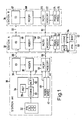
- Fig. 1 shows a simplified block diagram having three cooperating stations AK (30), A (32) and B (34). Stations AK, A have identical elements, some thereof have no counterpart in station B. Normally communication takes place between only two stations at any instant. Station AK represents a personal data carrier shaped as an active card. Station AK comprises an identification device ID (36) for identification towards a station communicating with station AK, for example, towards station A. Furthermore station AK comprises a modification device modifi (38) which receives number values that are exchanged during the process of mutual identification for by modification thereof generating a message ciphering key. The message ciphering key is used thereafter for ciphering and deciphering data in a combined ciphering/deciphering device MCRY/MDECRY (44/46). The data to be transmitted from station AK are produced by a message generator MGEN (4o) and messages received are sent to a message receiver MREC (42).
- The station AK also comprises a key set PIN (32) for entering into the card a personal secret code of the owner, that is a so-called PIN code. The supplied personal code is transmitted to an evaluation device (34) comprising a
comparator circuit COINC 80 and a referencecode memory REF 78. In memory REF the corresponding correct personal code is stored, which code is supplied to said comparator circuit. When equality is detected between the personal code which is entered and the one which is stored, the comparator circuit generates a signal which is supplied to an activatingmeans ACT 82 which will then activate temporarily' the further functions on the active card by means of a control signal online 83. Only during this temporary activation the card AK and the cooperating station A (32) may execute mutual identification and exchange data messages. Advantageously, the activating means ACT may be so dimensioned that the card will be inactivated automatically when the transmission is finished, for example after a predetermined time interval or by means of a reset mechanism triggered by an "end of message" signal. Before the next-following data exchange station AK must be activated again by a renewed supply of said PIN code. In this way an increased safety against unauthorized use of station AK is realized. - Fig. 1 also shows two stations A and B, which for example may have a form of a bank terminal device or a POS device. Like station AK each of the stations A and B, respectively, comprises an identification device ID, 48, 66 a
modification device MODIFI MDECRY 52/54, 70/72 and a message generator/receiver MGEN,MREC 56/58, 74/76. Like station AK the stations A and B may comprise said means for a PIN controlled activation, that is the means PIN, REF, COINC, ACT (60-66) as shown in station A. In certain cases the latter sub-system may be omitted as has been shown for station B. - The stations may be interconnected via a transmission channel which in Fig. 1 is represented by double arrows 86-92 between the identification and message enciphering/deciphering devices thereof. The transmission channel may comprise a galvanic coupling or a radio connection and may comprise a channel of a time divisional multiplex system or a frequency divisional multiplex system. In the case of bank terminals the transmission channel may comprise a part of the general data network. For
example lines 86, 88 may be embodied in a single lead or time/frequency slot. It is stressed that a communication may be set up via one or more further stations, which than merely relay the information unchanged. Thus a communication session could be executed directly between stations AK and B, station A then merely relaying the messages. - The diagram of Fig. 2 shows the introductory operational steps for a transmission between the station A and the station B via the transmission channel CH. The diagram comprises a column ST in which the operational steps are numbered sequentially. The numbering of the operational steps has been done without considering the fact that some of the steps may be carried out simultaneously in the respective stations. As a consequence the number of steps may be lower in the time space. Furthermore the diagram comprises for each station a column MEM, in which is indicated what is stored in the station at each step, and a column OPERA indicating the operations carried out by the station. In the column CH the transmission sequences on the transmission channel are shown. Furthermore, reference is already had to the more detailed block diagram of a station shown in Fig. 3.
- This embodiment of the identification process uses an identification enciphering function E and its inverse D, operating with double keys, i.e. each station has an enciphering key and a deciphering key associated therewith. The ciphering key is public, i.e. it is available (known) to all stations in the system,'but the deciphering key of the station is kept secret in the station.
- The relation between the ciphering key k and the associated deciphering key d is unique and may be expressed by means of a function F as follows


- The ciphering function which is used in combination with a pair of keys k, d is a so-called "trap door function". A trap door function has the character of a one-way function to anybody not having available the complete information, i.e. both of said keys k and d and said function and its inverse.
- C = Mk mod n (1), in which C designates the cipher of the message M, k designates the public ciphering key, n is an integer and (mod n) designates a function which is the reminder after a repeated devision by n.
- The trap door character of the function means that deciphering may be obtained only with a knowledge about the associated secret deciphering key d by means of the function M = Cd mod (2).
- In this trap door function the following relation is valid between the keys k and d

- Said ciphering and deciphering function E and D, respectively, may be according to expressions (1) and (2) above. If so, the key pairs which are used fulfill the relation (3).
- In the'diagram of Fig. 2 the following designations are also used:


- In addition to what is shown in columns MEM, each station knows from the beginning the publicity known functions E, D, f, t, TM, and
T m. The function f may be realized by the same trap door function as said ciphering function E, which is obtained by selecting one of the keys of a pair of keys as a constant key and by ignoring the other one. - _ The message ciphering function TM and the inverse thereof
T M, used together with the established so-called session key t , is of the type which operates with one key which is known to both transmitter and receiver. Several ciphering functions of this type are known. An adequate choice is the so-called DES function or algorithm, in which DES stands for "The United States Data Encryption Algorithm". For a detailed description of this algorithm is referred to Federal Information Processing Standards Publication 46 (January 15, 1977) by United States Dept. of Commerce/National Bureau of Standards. - From the diagram in Fig. 2 is evident that each station from start,
step 0, has in storage its own secret deciphering key and the public ciphering key of the other station. The mutual identification begins with station A generating and storing a number r1, preferably a pseudo-random number. Duringstep 2, r1 is ciphered by means of kb to produce s1. A first cipher cg1 is formed from s1 and the address a of the station A and is transmitted in step 3 to station B. - Station B receives cg1 and in step 4 calculates r1 by deciphering s1 while using db; r1 is stored. In step 5 the result of the transformation function f from the received number value r1 is calculated, which gives s2.
Step number 6 means generation of a second number value r2, being preferably a second pseudo-random number, which is also stored. The next step (7) means that r2 is ciphered by using the key ka, which gives s3. During the following step 8 a second cipher cg2 is transmitted to station A comprising s2, s3, b. - The station A receives cg2. This is followed (9) by a calculation of the result of the transformation function from its own number value r1, which result, in the next step (10), is compared with the corresponding result of station B, that is s2, which was received in the second cipher. In case of disagreement, the blocking signal BL is generated during
step number 11, said signal blocking or breaking the connection between the stations. In case of agreement, the number value r2 is calculated (12) by deciphering s3 received in the second cipher. At the same time the calculated r2 is stored. - As evident from the columns MEM at this stage, (step number 12), both of the stations know both r1 and r2. During the next following
step 13, the station A calculates the session key tm from r1, r2. At the same time t is stored. Thereafter the outcome of the trans- m formation function f from the detected r2 is calculated, which gives s4, which is transmitted in a third cipher cg 3 to station B. - The station B receives cg3 and calculates during the following step (16), the outcome of the transformation function f from its own number value r2, which outcome is thereafter compared with the corresponding outcome of station A, that is s4, which was received in said third cipher. In case of disagreement, the blocking signal BL is generated during
step number 18, which signal blocks or breaks the connection with station A. In case of agreement, the session key tm is calculated and stored (19). - The mutual identification has now been obtained and if the connection is maintained both parties have available the established session key tm, which means that the text or data message transmission may begin. Therefore the station A ciphers (20) a first message M1 while using tm, which gives the result TM1, which, during the next following
step 21, is transmitted to the station B and received thereby. In the station B, TM1 is deciphered while using tm, which gives the result M1 (22). In similar way, further messages may be sent in one or in both directions, until the intended packet of data has been transmitted, whereafter the communication is terminated by an end-of-communication signal. In Fig. 2 the use of the PIN code has not been considered explicitly because this represents an earlier stage in time. - Because the station A has available tm already at
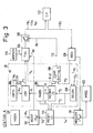
step number 13 the first ciphered message TM1 may be transmitted together with the third cipher cg3. Consequently, only one separate transmission sequence in each direction is required in order to carry out the identification and the establishment of a session key. - Fig. 3 shows a more detailed functional block diagram of the station A. The cooperation between the blocks is illustrated by the signals which are generated in the station A according to the diagram of Fig. 2. Accordingly, the time of appearance of said signals may be obtained from the diagram. Fig. 3 is intended to illustrate cooperating functional blocks, which may also be realized by providing a computer or microcomputer with the necessary software. Consequently respective different blocks in Fig. 3 may be realized by means of the samehardware, and Fig. 3 cannot be considered a one-to-one picture of a device. In consequence the required data paths, control decoders, timing means and the like have not been shown for brevity.
- The
identification device ID 36 is indicated by a dotted line. ID comprises anumber generator NGEN 100 for generating the number value r1 of the station. The number generator comprises a pseudo-random generator built as a feedback coupled shift register. The number value r1 is supplied to a ciphering device CRY (102) comprising the means for ciphering r1 by means of said trap door function using the public ciphering key kb of the counterpart, which is obtained from a key memory CRYK (104). - The device ID furthermore comprises a deciphering device DECRY (106), comprising the means for realizing the inverse of said trap door function. In this deciphering device the number value r2 of the other station is calculated while using the secret deciphering key da of the station, which is obtained from the key memory CRYK (104). The device furthermore comprises a comparator COMP 108. To the comparator a converted version f(rl) or r1 is supplied from a number converter NCONV (110), the latter converting the number values which are supplied thereto according to the one way function f. As a second input signal the comparator COMP receives the information s2, that is the information r1 as converted by the other station. The comparator also has means for generating the blocking signal BL on
output 112 when inequality is detected. - The number values r1 and r2 are supplied to a
modification device MODIFI 114 comprising the means for forming, from said number values, a session key tm according to a fixed modification algorithm t, which may have the meaning of a simple addition, bit-wise EXCLUSIVE ORING, concatenation or a different combination of the number values. The formed session key t m is supplied on the one hand to a message ciphering device MCRY (116) and on the other hand to a message deciphering device MDECRY (118) comprising the means for the realisation of said message ciphering algorithm TM and said message deciphering algorithmT M, respectively. These may comprise for example standardized circuits for the realisation of the DES algorithm mentioned above. To themessage ciphering device 116 are supplied data messages to be transmitted in the ciphered form to station B, from a message generator MGEN (120). Correspondingly, the output of message deciphering device is connected to a memory MREC (122) for the data messages which are received. - The station A also comprises a transmission unit TRU (124) comprising the means for formatting the transmission sequences which are transmitted by the station. To said transmission unit is connected an address generator ADRGEN (126) for generating the station address a. Accordingly, the transmission unit will for example put together the cipher cg1 from the signal a received from
address generator 126 and s1 received from cypheringdevice 102. In correspondence there is comprised areception unit REU 128 having the means for directing the signals of the received signal sequences to the relevant functional blocks. Accordingly, in the received cipher cg2 the signal s2 is directed to the comparator COMP (l08) and the signal s3 is directed to the deciphering device DECRY (106), and further messages are forwarded to themessage deciphering device 118. Likewise thetransmission unit 124 is also connected tomessage encyphering unit 116 for therefrom receiving further messages TM1 to be sent to the other station. Finally, a dotted line has been shown fromnumber converter 110 totransmission unit 124 to communicate the information s4, calculated according to step 14 in Fig. 2. - As mentioned already the comparator COMP generates a blocking signal BL at non-coincidence, i.e. in case the station B has not been able to identify itself towards the station A by transmitting back a correctly converted r1. The blocking signal is used for the control of a
blocking device BLS 130, which is illustrated as a switch. The appearance of signal BL breaks the connection between the transmission unit TRU and thechannel CH 132 and thereby also the connection between the stations. The channel is bidirectionally operative, while the separation between data-out and data-in is executed inelements
Claims (13)
Applications Claiming Priority (2)
| Application Number | Priority Date | Filing Date | Title |
|---|---|---|---|
| SE8102268A SE426128B (en) | 1981-04-08 | 1981-04-08 | METHOD FOR TRANSFER OF DATA MESSAGES BETWEEN TWO STATIONS, AND TRANSFER PLANT FOR EXECUTING THE METHOD |
| SE8102268 | 1981-04-08 |
Publications (3)
| Publication Number | Publication Date |
|---|---|
| EP0064779A2 true EP0064779A2 (en) | 1982-11-17 |
| EP0064779A3 EP0064779A3 (en) | 1984-07-25 |
| EP0064779B1 EP0064779B1 (en) | 1986-10-29 |
Family
ID=20343561
Family Applications (1)
| Application Number | Title | Priority Date | Filing Date |
|---|---|---|---|
| EP82200425A Expired EP0064779B1 (en) | 1981-04-08 | 1982-04-07 | Method and system for the mutual encyphered identification between data communicating stations and stations for use with such method and system |
Country Status (5)
| Country | Link |
|---|---|
| US (1) | US4720859A (en) |
| EP (1) | EP0064779B1 (en) |
| CA (1) | CA1191916A (en) |
| DE (1) | DE3274043D1 (en) |
| SE (1) | SE426128B (en) |
Cited By (16)
| Publication number | Priority date | Publication date | Assignee | Title |
|---|---|---|---|---|
| DE3300170A1 (en) * | 1983-01-05 | 1984-07-12 | DATA-LÖSCH Gesellschaft für Sicherheitstechniken im Datenschutz mbH, 4420 Coesfeld | Blocking-unit control system |
| EP0131906A2 (en) * | 1983-07-15 | 1985-01-23 | Tandem Computers Incorporated | Pocket banking terminal, method and system |
| FR2549989A1 (en) * | 1983-07-29 | 1985-02-01 | Philips Ind Commerciale | AUTHENTICATION SYSTEM BETWEEN A CARD READER AND A PAYMENT CARD EXCHANGING INFORMATION |
| EP0148015A2 (en) * | 1983-12-30 | 1985-07-10 | S. P. Radio A/S | A method for cryptographic transmission of speech signals and a communication station for performing the method |
| EP0148960A1 (en) * | 1983-12-21 | 1985-07-24 | International Business Machines Corporation | Security in data communication systems |
| EP0197392A2 (en) * | 1985-04-11 | 1986-10-15 | International Business Machines Corporation | Improvements in cryptographic communication |
| EP0225010A1 (en) * | 1985-09-30 | 1987-06-10 | BRITISH TELECOMMUNICATIONS public limited company | A terminal for a system requiring secure access |
| EP0253722A1 (en) * | 1986-07-17 | 1988-01-20 | Bull Cp8 | Method for diversifying a basic key and for authenticating a key worked out from a predetermined basic key and system for operation |
| GB2194419A (en) * | 1986-08-08 | 1988-03-02 | British Broadcasting Corp | Data encipherment |
| EP0281057A2 (en) * | 1987-03-04 | 1988-09-07 | Siemens Nixdorf Informationssysteme Aktiengesellschaft | Circuitry for securing the access to a data processor by means of an IC card |
| EP0386677A2 (en) * | 1989-03-08 | 1990-09-12 | Siemens Nixdorf Informationssysteme Aktiengesellschaft | Method for the generation of a random number for encyphered data transmission, using a variable start-value |
| EP0511483A2 (en) * | 1991-04-01 | 1992-11-04 | International Business Machines Corporation | Method and apparatus for authenticating users of a communication system to each other |
| EP0588339A2 (en) * | 1992-09-18 | 1994-03-23 | Nippon Telegraph And Telephone Corporation | Method and apparatus for settlement of accounts by IC cards |
| GB2278518A (en) * | 1993-05-14 | 1994-11-30 | Trafford Limited | Encrypted data transfer |
| GB2296639B (en) * | 1993-09-14 | 1998-01-21 | Chantilley Corp Ltd | Apparatus for key distribution in an encryption system |
| US5729717A (en) * | 1984-01-31 | 1998-03-17 | Kabushiki Kaisha Toshiba | IC card and issuing apparatus allowing multiple applications |
Families Citing this family (37)
| Publication number | Priority date | Publication date | Assignee | Title |
|---|---|---|---|---|
| US4799061A (en) * | 1985-11-18 | 1989-01-17 | International Business Machines Corporation | Secure component authentication system |
| US4916738A (en) * | 1986-11-05 | 1990-04-10 | International Business Machines Corp. | Remote access terminal security |
| GB8819767D0 (en) * | 1988-08-19 | 1989-07-05 | Ncr Co | Public key diversification method |
| US4910777A (en) * | 1988-09-20 | 1990-03-20 | At&T Bell Laboratories | Packet switching architecture providing encryption across packets |
| US5196840A (en) * | 1990-11-05 | 1993-03-23 | International Business Machines Corporation | Secure communications system for remotely located computers |
| JP2901767B2 (en) * | 1991-02-08 | 1999-06-07 | 株式会社東芝 | Cryptographic communication system and portable electronic device |
| EP0537903A2 (en) * | 1991-10-02 | 1993-04-21 | International Business Machines Corporation | Distributed control system |
| NL9101796A (en) * | 1991-10-25 | 1993-05-17 | Nederland Ptt | METHOD FOR AUTHENTICATING COMMUNICATION PARTICIPANTS, METHOD FOR USING THE METHOD AND FIRST COMMUNICATION PARTICIPANT AND SECOND COMMUNICATION PARTICIPANT FOR USE IN THE SYSTEM. |
| US5557518A (en) * | 1994-04-28 | 1996-09-17 | Citibank, N.A. | Trusted agents for open electronic commerce |
| US5267314A (en) * | 1992-11-17 | 1993-11-30 | Leon Stambler | Secure transaction system and method utilized therein |
| US5481611A (en) * | 1993-12-09 | 1996-01-02 | Gte Laboratories Incorporated | Method and apparatus for entity authentication |
| US5491749A (en) * | 1993-12-30 | 1996-02-13 | International Business Machines Corporation | Method and apparatus for entity authentication and key distribution secure against off-line adversarial attacks |
| US5491750A (en) * | 1993-12-30 | 1996-02-13 | International Business Machines Corporation | Method and apparatus for three-party entity authentication and key distribution using message authentication codes |
| US5692049A (en) * | 1995-02-13 | 1997-11-25 | Eta Technologies Corporation | Personal access management system |
| US5689564A (en) * | 1995-02-13 | 1997-11-18 | Eta Technologies Corporation | Personal access management system |
| US5778068A (en) * | 1995-02-13 | 1998-07-07 | Eta Technologies Corporation | Personal access management system |
| US5694472A (en) * | 1995-02-13 | 1997-12-02 | Eta Technologies Corporation | Personal access management system |
| US5610980A (en) * | 1995-02-13 | 1997-03-11 | Eta Technologies Corporation | Method and apparatus for re-initializing a processing device and a storage device |
| US5696825A (en) * | 1995-02-13 | 1997-12-09 | Eta Technologies Corporation | Personal access management system |
| US5619574A (en) * | 1995-02-13 | 1997-04-08 | Eta Technologies Corporation | Personal access management system |
| US5682428A (en) * | 1995-02-13 | 1997-10-28 | Eta Technologies Corporation | Personal access management system |
| US5923762A (en) * | 1995-12-27 | 1999-07-13 | Pitney Bowes Inc. | Method and apparatus for ensuring debiting in a postage meter prior to its printing a postal indicia |
| US5799290A (en) * | 1995-12-27 | 1998-08-25 | Pitney Bowes Inc. | Method and apparatus for securely authorizing performance of a function in a distributed system such as a postage meter |
| GB9601924D0 (en) * | 1996-01-31 | 1996-04-03 | Certicom Corp | Transaction verification protocol for smart cards |
| US5841872A (en) * | 1996-07-01 | 1998-11-24 | Allsoft Distributing Incorporated | Encryption enhancement system |
| US6041123A (en) * | 1996-07-01 | 2000-03-21 | Allsoft Distributing Incorporated | Centralized secure communications system |
| US6247129B1 (en) | 1997-03-12 | 2001-06-12 | Visa International Service Association | Secure electronic commerce employing integrated circuit cards |
| JP3864401B2 (en) | 1997-04-23 | 2006-12-27 | ソニー株式会社 | Authentication system, electronic device, authentication method, and recording medium |
| JP3951464B2 (en) | 1998-07-28 | 2007-08-01 | 株式会社日立製作所 | Digital signal processor |
| GB2348568A (en) * | 1999-03-31 | 2000-10-04 | Ibm | Enabling conformance to legislative requirements for mobile devices |
| JP4177514B2 (en) * | 1999-04-28 | 2008-11-05 | 株式会社東芝 | Computer system and content protection method |
| DE10164135A1 (en) * | 2001-12-30 | 2003-07-17 | Juergen K Lang | Multimedia protection system divides data for part encryption with variable length key |
| DE10164134A1 (en) * | 2001-12-30 | 2003-07-17 | Juergen K Lang | System for preparing and distributing copyright-protected electronic media in a receiver, involves encoding data for reproduction after applying cryptographic processes. |
| DE10164133A1 (en) * | 2001-12-30 | 2003-07-17 | Juergen K Lang | System for storing and reproducing copyright-/use-protected electronic sound/image media in a receiver encodes data for electronic media subject to cryptographic processes. |
| DE10164131A1 (en) * | 2001-12-30 | 2003-07-17 | Juergen K Lang | Cryptographic module for the storage and playback of copy and usage protected electronic audio and video media |
| DE10352071A1 (en) * | 2003-11-07 | 2005-06-23 | Daimlerchrysler Ag | Method for detecting unauthorized component exchange |
| US7761591B2 (en) | 2005-12-16 | 2010-07-20 | Jean A. Graham | Central work-product management system for coordinated collaboration with remote users |
Citations (2)
| Publication number | Priority date | Publication date | Assignee | Title |
|---|---|---|---|---|
| EP0002580A1 (en) * | 1977-12-05 | 1979-06-27 | International Business Machines Corporation | A process for the verification of cryptographic operational keys used in data communication networks |
| GB2050021A (en) * | 1979-05-21 | 1980-12-31 | Atalla Technovations | Method and means for securing the distribution of encoding keys |
Family Cites Families (13)
| Publication number | Priority date | Publication date | Assignee | Title |
|---|---|---|---|---|
| US4206315A (en) * | 1978-01-04 | 1980-06-03 | International Business Machines Corporation | Digital signature system and apparatus |
| US4408203A (en) * | 1978-01-09 | 1983-10-04 | Mastercard International, Inc. | Security system for electronic funds transfer system |
| US4186871A (en) * | 1978-03-01 | 1980-02-05 | International Business Machines Corporation | Transaction execution system with secure encryption key storage and communications |
| GB2020513B (en) * | 1978-05-03 | 1982-12-22 | Atalla Technovations | Method and apparatus for securing data transmissions |
| US4264782A (en) * | 1979-06-29 | 1981-04-28 | International Business Machines Corporation | Method and apparatus for transaction and identity verification |
| FR2469760A1 (en) * | 1979-11-09 | 1981-05-22 | Cii Honeywell Bull | METHOD AND SYSTEM FOR IDENTIFYING PEOPLE REQUESTING ACCESS TO CERTAIN MEDIA |
| US4302810A (en) * | 1979-12-28 | 1981-11-24 | International Business Machines Corporation | Method and apparatus for secure message transmission for use in electronic funds transfer systems |
| US4326098A (en) * | 1980-07-02 | 1982-04-20 | International Business Machines Corporation | High security system for electronic signature verification |
| US4393269A (en) * | 1981-01-29 | 1983-07-12 | International Business Machines Corporation | Method and apparatus incorporating a one-way sequence for transaction and identity verification |
| DE3123168C1 (en) * | 1981-06-11 | 1982-11-04 | Siemens AG, 1000 Berlin und 8000 München | Key transfer procedure |
| US4423287A (en) * | 1981-06-26 | 1983-12-27 | Visa U.S.A., Inc. | End-to-end encryption system and method of operation |
| US4652698A (en) * | 1984-08-13 | 1987-03-24 | Ncr Corporation | Method and system for providing system security in a remote terminal environment |
| US4649233A (en) * | 1985-04-11 | 1987-03-10 | International Business Machines Corporation | Method for establishing user authenication with composite session keys among cryptographically communicating nodes |
-
1981
- 1981-04-08 SE SE8102268A patent/SE426128B/en not_active IP Right Cessation
-
1982
- 1982-03-31 CA CA000400150A patent/CA1191916A/en not_active Expired
- 1982-04-05 US US06/365,711 patent/US4720859A/en not_active Expired - Lifetime
- 1982-04-07 DE DE8282200425T patent/DE3274043D1/en not_active Expired
- 1982-04-07 EP EP82200425A patent/EP0064779B1/en not_active Expired
Patent Citations (2)
| Publication number | Priority date | Publication date | Assignee | Title |
|---|---|---|---|---|
| EP0002580A1 (en) * | 1977-12-05 | 1979-06-27 | International Business Machines Corporation | A process for the verification of cryptographic operational keys used in data communication networks |
| GB2050021A (en) * | 1979-05-21 | 1980-12-31 | Atalla Technovations | Method and means for securing the distribution of encoding keys |
Non-Patent Citations (2)
| Title |
|---|
| IBM TECHNICAL DISCLOSURE BULLETIN, vol. 22, no. 2, July 1979, pages 643-646, New York (USA); R.E. LENNON et al.: "Composite cryptographic session keys for enhanced communication security". * |
| PROCEEDINGS OF 1982 INTERNATIONAL ZURICH SEMINAR ON DIGITAL COMMUNICATIONS - MAN-MACHINE INTERACTION, 9th-11th March 1982, pages 87-92, Swiss Federal Institute of Technology, Z}rich (CH); M. DAVIO et al.: "Methodology in information security. Mutual authentication procedures. Application to access control". * |
Cited By (28)
| Publication number | Priority date | Publication date | Assignee | Title |
|---|---|---|---|---|
| DE3300170A1 (en) * | 1983-01-05 | 1984-07-12 | DATA-LÖSCH Gesellschaft für Sicherheitstechniken im Datenschutz mbH, 4420 Coesfeld | Blocking-unit control system |
| EP0131906A2 (en) * | 1983-07-15 | 1985-01-23 | Tandem Computers Incorporated | Pocket banking terminal, method and system |
| EP0131906A3 (en) * | 1983-07-15 | 1987-10-14 | Atalla Corporation | Pocket banking terminal, method and system |
| FR2549989A1 (en) * | 1983-07-29 | 1985-02-01 | Philips Ind Commerciale | AUTHENTICATION SYSTEM BETWEEN A CARD READER AND A PAYMENT CARD EXCHANGING INFORMATION |
| EP0148960A1 (en) * | 1983-12-21 | 1985-07-24 | International Business Machines Corporation | Security in data communication systems |
| EP0148015A2 (en) * | 1983-12-30 | 1985-07-10 | S. P. Radio A/S | A method for cryptographic transmission of speech signals and a communication station for performing the method |
| EP0148015A3 (en) * | 1983-12-30 | 1986-11-26 | Sp Radio As | A method for cryptographic transmission of speech signals and a communication station for performing the method |
| US4856061A (en) * | 1983-12-30 | 1989-08-08 | S.P. Radio A/S | Method for cryptographic transmission of speech signals and a communication station for performing the method |
| US5729717A (en) * | 1984-01-31 | 1998-03-17 | Kabushiki Kaisha Toshiba | IC card and issuing apparatus allowing multiple applications |
| EP0197392A3 (en) * | 1985-04-11 | 1988-12-14 | International Business Machines Corporation | Improvements in cryptographic communication |
| EP0197392A2 (en) * | 1985-04-11 | 1986-10-15 | International Business Machines Corporation | Improvements in cryptographic communication |
| EP0225010A1 (en) * | 1985-09-30 | 1987-06-10 | BRITISH TELECOMMUNICATIONS public limited company | A terminal for a system requiring secure access |
| WO1988000744A1 (en) * | 1986-07-17 | 1988-01-28 | Bull Cp8 | Process for diversifying a basic key and for authenticating a thus diversified key as having been prepared from a predetermined basic key, and system for its implementation |
| US4811393A (en) * | 1986-07-17 | 1989-03-07 | Bull, S.A. | Method and system for diversification of a basic key and for authentication of a thus-diversified key |
| FR2601795A1 (en) * | 1986-07-17 | 1988-01-22 | Bull Cp8 | METHOD FOR DIVERSIFYING A BASE KEY AND FOR AUTHENTICATING A KEY SO DIVERSIFIED AS PREPARED BY A PREDETERMINED BASE KEY, AND SYSTEM FOR IMPLEMENTING THE SAME |
| EP0253722A1 (en) * | 1986-07-17 | 1988-01-20 | Bull Cp8 | Method for diversifying a basic key and for authenticating a key worked out from a predetermined basic key and system for operation |
| GB2194419A (en) * | 1986-08-08 | 1988-03-02 | British Broadcasting Corp | Data encipherment |
| EP0281057A2 (en) * | 1987-03-04 | 1988-09-07 | Siemens Nixdorf Informationssysteme Aktiengesellschaft | Circuitry for securing the access to a data processor by means of an IC card |
| EP0281057B1 (en) * | 1987-03-04 | 1994-05-11 | Siemens Nixdorf Informationssysteme Aktiengesellschaft | Circuitry for securing the access to a data processor by means of an IC card |
| EP0386677B1 (en) * | 1989-03-08 | 1994-01-05 | Siemens Nixdorf Informationssysteme Aktiengesellschaft | Method for the generation of a random number for encyphered data transmission, using a variable start-value |
| EP0386677A2 (en) * | 1989-03-08 | 1990-09-12 | Siemens Nixdorf Informationssysteme Aktiengesellschaft | Method for the generation of a random number for encyphered data transmission, using a variable start-value |
| EP0511483A3 (en) * | 1991-04-01 | 1993-06-09 | International Business Machines Corporation | Method and apparatus for authenticating users of a communication system to each other |
| EP0511483A2 (en) * | 1991-04-01 | 1992-11-04 | International Business Machines Corporation | Method and apparatus for authenticating users of a communication system to each other |
| EP0588339A2 (en) * | 1992-09-18 | 1994-03-23 | Nippon Telegraph And Telephone Corporation | Method and apparatus for settlement of accounts by IC cards |
| EP0588339A3 (en) * | 1992-09-18 | 1995-05-24 | Nippon Telegraph & Telephone | Method and apparatus for settlement of accounts by IC cards. |
| GB2278518A (en) * | 1993-05-14 | 1994-11-30 | Trafford Limited | Encrypted data transfer |
| GB2278518B (en) * | 1993-05-14 | 1997-12-10 | Trafford Limited | Encrypted data transfer |
| GB2296639B (en) * | 1993-09-14 | 1998-01-21 | Chantilley Corp Ltd | Apparatus for key distribution in an encryption system |
Also Published As
| Publication number | Publication date |
|---|---|
| CA1191916A (en) | 1985-08-13 |
| EP0064779B1 (en) | 1986-10-29 |
| DE3274043D1 (en) | 1986-12-04 |
| SE426128B (en) | 1982-12-06 |
| SE8102268L (en) | 1982-10-09 |
| EP0064779A3 (en) | 1984-07-25 |
| US4720859A (en) | 1988-01-19 |
Similar Documents
| Publication | Publication Date | Title |
|---|---|---|
| US4720859A (en) | Method and system for the mutual encyphered indentification between data communicating stations and stations for use with such method and system | |
| US4912762A (en) | Management of cryptographic keys | |
| EP0047285B1 (en) | A system for authenticating users and devices in on-line transaction networks | |
| EP0137999B1 (en) | Improvements in point of sale and electronic funds transfer systems | |
| US4747050A (en) | Transaction security system using time variant parameter | |
| US5371796A (en) | Data communication system | |
| EP0186981B1 (en) | Security module for an electronic funds transfer system | |
| EP0354774B1 (en) | Data cryptography using control vectors | |
| EP0007002B1 (en) | Transaction terminal systems provided with potential user authentication | |
| EP0131906B1 (en) | Pocket banking terminal, method and system | |
| US4918728A (en) | Data cryptography operations using control vectors | |
| US6163771A (en) | Method and device for generating a single-use financial account number | |
| US7844550B2 (en) | Method and device for generating a single-use financial account number | |
| US4438824A (en) | Apparatus and method for cryptographic identity verification | |
| US5343529A (en) | Transaction authentication using a centrally generated transaction identifier | |
| EP0082958A2 (en) | Cryptographic data communications | |
| JP2000516734A (en) | Certainty certification system | |
| WO1997045979A2 (en) | Method and apparatus for initialization of cryptographic terminal | |
| EP0148960B1 (en) | Security in data communication systems | |
| GB2267631A (en) | Data communication system |
Legal Events
| Date | Code | Title | Description |
|---|---|---|---|
| PUAI | Public reference made under article 153(3) epc to a published international application that has entered the european phase |
Free format text: ORIGINAL CODE: 0009012 |
|
| 17P | Request for examination filed |
Effective date: 19820407 |
|
| AK | Designated contracting states |
Designated state(s): DE FR GB SE |
|
| PUAL | Search report despatched |
Free format text: ORIGINAL CODE: 0009013 |
|
| AK | Designated contracting states |
Designated state(s): DE FR GB SE |
|
| RAP1 | Party data changed (applicant data changed or rights of an application transferred) |
Owner name: N.V. PHILIPS' GLOEILAMPENFABRIEKEN Owner name: PHILIPS NORDEN AB |
|
| GRAA | (expected) grant |
Free format text: ORIGINAL CODE: 0009210 |
|
| AK | Designated contracting states |
Kind code of ref document: B1 Designated state(s): DE FR GB SE |
|
| PG25 | Lapsed in a contracting state [announced via postgrant information from national office to epo] |
Ref country code: SE Effective date: 19861031 |
|
| REF | Corresponds to: |
Ref document number: 3274043 Country of ref document: DE Date of ref document: 19861204 |
|
| ET | Fr: translation filed | ||
| PLBE | No opposition filed within time limit |
Free format text: ORIGINAL CODE: 0009261 |
|
| STAA | Information on the status of an ep patent application or granted ep patent |
Free format text: STATUS: NO OPPOSITION FILED WITHIN TIME LIMIT |
|
| 26N | No opposition filed | ||
| REG | Reference to a national code |
Ref country code: FR Ref legal event code: CD |
|
| REG | Reference to a national code |
Ref country code: FR Ref legal event code: CD |
|
| PGFP | Annual fee paid to national office [announced via postgrant information from national office to epo] |
Ref country code: FR Payment date: 20000426 Year of fee payment: 19 |
|
| PGFP | Annual fee paid to national office [announced via postgrant information from national office to epo] |
Ref country code: GB Payment date: 20000428 Year of fee payment: 19 |
|
| PGFP | Annual fee paid to national office [announced via postgrant information from national office to epo] |
Ref country code: DE Payment date: 20000621 Year of fee payment: 19 |
|
| PG25 | Lapsed in a contracting state [announced via postgrant information from national office to epo] |
Ref country code: GB Free format text: LAPSE BECAUSE OF NON-PAYMENT OF DUE FEES Effective date: 20010407 |
|
| PG25 | Lapsed in a contracting state [announced via postgrant information from national office to epo] |
Ref country code: FR Free format text: THE PATENT HAS BEEN ANNULLED BY A DECISION OF A NATIONAL AUTHORITY Effective date: 20010430 Ref country code: DE Free format text: LAPSE BECAUSE OF NON-PAYMENT OF DUE FEES Effective date: 20010430 |
|
| GBPC | Gb: european patent ceased through non-payment of renewal fee |
Effective date: 20010407 |
|
| REG | Reference to a national code |
Ref country code: FR Ref legal event code: ST |