EP0063902A1 - An ink jet printing machine - Google Patents
An ink jet printing machine Download PDFInfo
- Publication number
- EP0063902A1 EP0063902A1 EP82301962A EP82301962A EP0063902A1 EP 0063902 A1 EP0063902 A1 EP 0063902A1 EP 82301962 A EP82301962 A EP 82301962A EP 82301962 A EP82301962 A EP 82301962A EP 0063902 A1 EP0063902 A1 EP 0063902A1
- Authority
- EP
- European Patent Office
- Prior art keywords
- nozzles
- housings
- adjacent
- printing machine
- machine according
- Prior art date
- Legal status (The legal status is an assumption and is not a legal conclusion. Google has not performed a legal analysis and makes no representation as to the accuracy of the status listed.)
- Granted
Links
Images


Classifications
-
- B—PERFORMING OPERATIONS; TRANSPORTING
- B41—PRINTING; LINING MACHINES; TYPEWRITERS; STAMPS
- B41J—TYPEWRITERS; SELECTIVE PRINTING MECHANISMS, i.e. MECHANISMS PRINTING OTHERWISE THAN FROM A FORME; CORRECTION OF TYPOGRAPHICAL ERRORS
- B41J2/00—Typewriters or selective printing mechanisms characterised by the printing or marking process for which they are designed
- B41J2/005—Typewriters or selective printing mechanisms characterised by the printing or marking process for which they are designed characterised by bringing liquid or particles selectively into contact with a printing material
- B41J2/01—Ink jet
- B41J2/135—Nozzles
- B41J2/145—Arrangement thereof
Abstract
Description
- This invention relates generally to an ink jet printing machine, and more particularly concerns isolating adjacent ink jet nozzles from one another to prevent interaction therebetween.
- Generally, an ink jet printing machine has an array of small nozzles with each nozzle having a chamber containing ink associated therewith. Upon excitation, an electromechanical transducer varies the volume of the chamber producing a temporary increase in pressure forcing a droplet of ink to be ejected from the corresponding nozzle. These individual droplets of ink are sprayed onto a copy sheet. One column of vertical drops is referred to as a scan. If, in forming a character, a particular space in a scan is to be left blank, the transducer associated with the appropriate nozzle remains de-energized and a droplet of ink is not ejected from the nozzle. Thus, drops of ink are deposited in appropriate positions on the copy sheet to form the desired character. Ink jet printing machines of this type are described in U.S. Patent No. 3,683,212 issued to Zoltan in 1972; U.S. Patent No. 3,747,120 issued to Stemme in 1973; U.S. Patent No. 3,832,579 issued to Arndt in 1974; and U.S. Patent No. 3,871,004 issued to Rittberg in 1975.
- One of the problems in a printing machine of this type is excitation of the transducer associated with a selected nozzle frequently introduces cross-coupling between adjacent nozzles. Thus, not only may the desired nozzle be excited, but other nozzles adjacent thereto also may be excited.
- Various approaches have been devised to improve ink jet printing.
- U.S. Patent No. 4032929 discloses a multiple nozzle unit having an ink supply chamber. A piezoelectric layer is excited to deform or decrease the volume of the respective chamber to cause a droplet of ink to be ejected from the nozzle.
- U.S. Patent No. 4057807 describes an ink jet assembly in which excitation of an electromagnet deforms a diaphram to decrease the volume of an ink chamber. Decreasing the volume of the chamber causes ink to be ejected from a nozzle in communication therewith.
- U.S. Patent No. 4243995 describes an ink jet recording system in which a piezoelectric transducer is positioned partially in the ink channel. The piezoelectric transducer expands when excited acting like a piston to eject ink from the nozzle.
- An ink jet printing machine according to the present invention is characterised by an array of nozzles, means for storing a supply of writing fluid for each nozzle of said array of nozzles, means for energizing selected nozzles of said array of nozzles to eject spaced droplets of writing fluid therefrom, and means for isolating the nozzles of said array of nozzles from one another to prevent interaction between said nozzles from energizing nozzles other than the selected nozzles of said array of nozzles.
- In order that the invention may be more readily understood, reference will now be made to the accompanying drawings, in which:
- Figure 1 is an elevational view, partially in section, depicting an ink jet module of a machine of the present invention;
- Figure 2 is a sectional elevational view taken in the direction of the arrows 2 - 2 of Figure 1;
- Figure 3 is an elevational view, partially in section, showing an array of ink jet modules;
- Figure 4 is an elevational view, partially in section, showing another embodiment of an array of ink jet modules;
- Figure 5 is a fragmentary perspective view illustrating the corrugated members of Figure 4 for isolating adjacent ink jet modules from one another;
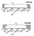
- Figure 6(a) is an elevational view showing one embodiment of the corrugated members depicted in Figure 5; and
- Figure 6(b) is an elevational view illustrating another embodiment of the corrugated members depicted in Figure 5.
- Referring to Figures 1 and 2, there is shown an
ink jet module 10 arranged to eject droplets of writing fluid or ink therefrom.Ink jet module 10 includes anozzle 12 in communication withtube 14 inhousing 16. Aninlet portion 18 oftube 14 is connected to a supply of writing ink. Apiezoelectric transducer 20 is positioned closelyadjacent tube 14.Piezoelectric transducer 20 is encapsulated in an elastomeric material such asurethane 22. An electric voltage pulse generator (not shown) is connected topiezoelectric transducer 20 byelectrical lead wire 24. Rectangular recessedportions 28 are formed inhousing 16 to define slots between adjacent ink jet modules. These slots are preferably filled with air so as to reduce cross coupling between adjacent ink jet modules. Alternatively, these slots may be filled with a liquid. All of the recessed portions are preferably about the same volume. In this manner, each recessed portion is one half of the volume of the slot separating adjacent ink jet modules. Excitation ofpiezoelectric tranducer 20 causestube 14 to be compressed or restricted in size. In this way, a droplet of ink or writing fluid is ejected fromnozzle 12. Preferably,piezoelectric transducer 20 is made from piezoceramic PZT-5, available from Vernitron Piezoelectric Division, Bedford, Ohio, U.S.A. -
Housing 16 is preferably formed by casting a plastic material, such as urethane.Piezoelectric transducer 20 is at least partially secured to housing 16.Nozzle 12 is also secured to housing 16. - As shown in Figure 3, a linear array of ink jet modules are formed by placing each ink jet module of Figure 2 adjacent to another. As depicted thereat, the
recessed portions 28 of adjacent ink jet modules are aligned with one another to define slots therebetween. In this way, adjacent ink jet assemblies are isolated from one another. This is achieved by the air spaces in the slots between adjacent modules. The air between adjacent ink jet modules acts as a damping medium to insure that surface to surface contact, between adjacent ink jet modules, is minimized. Hence, when one of the ink jet modules is actuated by energizing a selected piezoelectric transducer, adjacent ink jet modules remain de-activated, i.e. there is no cross coupling between the adjacent ink jet modules or interaction therebetween due to the isolation provided by the slots therebetween. Preferably, these slots are air filled, but the slots may be filled with any suitable fluid or visco-elastic damping medium, including a liquid. - Turning now to Figures 4 and 5, another embodiment of a linear array of ink jet modules is formed. As shown in Figure 4,
corrugated plates 29 are arranged between the modules. The plates may be formed with the sides of the modules or arranged in therecesses 28. In this way, adjacent ink jet assemblies are isolated from one another. This is achieved by the corrugations forming air spaces between adjacent modules. The air between adjacent ink jet modules acts as a damping medium. The corrugations insure that there is no surface to surface contact between adjacent ink jet modules, but rather a plurality of point contacts. Hence, when one of the ink jet modules is actuated by energizing a selected piezoelectric transducer, adjacent ink jet modules remain de-activated, i.e. there is no cross coupling between the adjacent ink jet modules or interaction therebetween due to the isolation provided bycorrugated plates 29. - As shown in Figure 5, a
wall 30 ofplate 29 intersects with awall 32 thereof at anapex 34. A plurality of apexes of a plate of one module contact the apexes of the plate of the next adjacent ink jet module. Thus, eachplate 29 is a corrugated member comprising a series of triangular members connected to one another. The axis formed by the apexes of oneplate 29 are substantially normal in direction to the axis formed by apexes of the next adjacent plate. In this way, a series of multiplicity of point contacts between adjacent ink jet modules occur rather than surface or area contact therebetween. Air is interposed between adjacent ink jet modules to provide damping therebetween. Preferably,wall 30intersects wall 32 of eachplate 29 at a 90° angle atapex 34. - Figure 6(a) depicts one embodiment of the relationship between
adjacent plates 29. As shown thereat, all of thewalls plate 29 intersect at the same angle atapex 34. As previously indicated, this angle is preferably 90°. Under these circumstances, all of theapexes 34 of onewall 29 will contact a!l of the apexes of the next adjacent wall. - Alternatively, as shown in Figure 6(b),
walls apexes 34 at different angles or the walls may be of different lengths. Under these circumstances, a plurality ofapexes 34 will be spaced from the nextadjacent plate 29. Thus, onlyperiodic apexes 34 will contact the nextadjacent plate 29. This further minimizes interaction between adjacent ink jet modules in that the contact therebetween is further reduced and more damping provided. The greater damping is introduced by the increase in air betweenadjacent plates 29. Moreover, the contact betweenadjacent plates 29 is greatly reduced in that contact will occur only periodically along discreet points rather than at each apex as is shown in Figure 5(a). - It will be appreciated that while
plates 29 have been depicted herein as being corrugated, other configurations may be employed. Thus, any plate having a plurality of protuberances extending outwardly therefrom may function to isolate adjacent ink jet modules from one another. These protuberances could be dimples, grooves, creases, or any other such arrangement. - In recapitulation, it is clear that the ink jet printing machine of the present invention includes a linear array of nozzles with adjacent nozzles being isolated from one another to prevent interaction therebetween when a selected nozzle is energized. Isolation of adjacent nozzles is achieved by interposing a damping medium therebetween. This damping medium is disposed in slots between adjacent nozzles and tends to prevent cross coupling. In this way, interaction is minimized and only the selected nozzle will be energized rather than both the selected nozzle and adjacent nozzles.
Claims (10)
Applications Claiming Priority (4)
| Application Number | Priority Date | Filing Date | Title |
|---|---|---|---|
| US06/255,017 US4377814A (en) | 1981-04-17 | 1981-04-17 | Ink jet printing machine |
| US255017 | 1981-04-17 | ||
| US06/305,583 US4390886A (en) | 1981-09-25 | 1981-09-25 | Ink jet printing machine |
| US305583 | 1999-05-05 |
Publications (2)
| Publication Number | Publication Date |
|---|---|
| EP0063902A1 true EP0063902A1 (en) | 1982-11-03 |
| EP0063902B1 EP0063902B1 (en) | 1985-06-26 |
Family
ID=26944382
Family Applications (1)
| Application Number | Title | Priority Date | Filing Date |
|---|---|---|---|
| EP19820301962 Expired EP0063902B1 (en) | 1981-04-17 | 1982-04-16 | An ink jet printing machine |
Country Status (2)
| Country | Link |
|---|---|
| EP (1) | EP0063902B1 (en) |
| DE (1) | DE3264403D1 (en) |
Citations (2)
| Publication number | Priority date | Publication date | Assignee | Title |
|---|---|---|---|---|
| US4032929A (en) * | 1975-10-28 | 1977-06-28 | Xerox Corporation | High density linear array ink jet assembly |
| US4243995A (en) * | 1979-06-01 | 1981-01-06 | Xerox Corporation | Encapsulated piezoelectric pressure pulse drop ejector apparatus |
-
1982
- 1982-04-16 EP EP19820301962 patent/EP0063902B1/en not_active Expired
- 1982-04-16 DE DE8282301962T patent/DE3264403D1/en not_active Expired
Patent Citations (2)
| Publication number | Priority date | Publication date | Assignee | Title |
|---|---|---|---|---|
| US4032929A (en) * | 1975-10-28 | 1977-06-28 | Xerox Corporation | High density linear array ink jet assembly |
| US4243995A (en) * | 1979-06-01 | 1981-01-06 | Xerox Corporation | Encapsulated piezoelectric pressure pulse drop ejector apparatus |
Also Published As
| Publication number | Publication date |
|---|---|
| DE3264403D1 (en) | 1985-08-01 |
| EP0063902B1 (en) | 1985-06-26 |
Similar Documents
| Publication | Publication Date | Title |
|---|---|---|
| EP0337429B1 (en) | Ink jet head | |
| CA2075783C (en) | High density ink jet printhead | |
| CA2075761C (en) | Sidewall actuator for a high density ink jet printhead | |
| US5365645A (en) | Methods of fabricating a page wide piezoelectric ink jet printhead assembly | |
| EP0402172B2 (en) | Head for ink-jet printer | |
| US4887100A (en) | Droplet deposition apparatus | |
| US5128694A (en) | Head for ink-jet printer | |
| EP0485241B1 (en) | Ink jet head | |
| US5751318A (en) | Elongated ink jet printhead using joined piezoelectric actuator | |
| EP0505188B1 (en) | Piezoelectric ink droplet ejecting device | |
| EP1316427B1 (en) | Inkjet head for inkjet printing apparatus | |
| US4390886A (en) | Ink jet printing machine | |
| US5202703A (en) | Piezoelectric transducers for ink jet systems | |
| EP0783409B1 (en) | Ink jet apparatus having a plurality of chambers with multiple orifices | |
| WO1994027826A1 (en) | Ink jet printhead assembly having aligned dual internal channel arrays | |
| US6050679A (en) | Ink jet printer transducer array with stacked or single flat plate element | |
| US4377814A (en) | Ink jet printing machine | |
| US6695439B2 (en) | Piezoelectric transducer and liquid droplet ejection device | |
| US20030103117A1 (en) | Inkjet head for inkjet printing apparatus | |
| EP0063902B1 (en) | An ink jet printing machine | |
| US4566018A (en) | Recorder operating with drops of liquid | |
| US5430470A (en) | Ink jet printhead having a modulatable cover plate | |
| EP0533506B1 (en) | Ink droplet ejection device | |
| JP3043936B2 (en) | Inkjet head | |
| EP1806228B1 (en) | Ink-jet head |
Legal Events
| Date | Code | Title | Description |
|---|---|---|---|
| PUAI | Public reference made under article 153(3) epc to a published international application that has entered the european phase |
Free format text: ORIGINAL CODE: 0009012 |
|
| AK | Designated contracting states |
Designated state(s): DE IT |
|
| 17P | Request for examination filed |
Effective date: 19830325 |
|
| ITF | It: translation for a ep patent filed |
Owner name: MODIANO & ASSOCIATI S.R.L. |
|
| GRAA | (expected) grant |
Free format text: ORIGINAL CODE: 0009210 |
|
| AK | Designated contracting states |
Designated state(s): DE IT |
|
| REF | Corresponds to: |
Ref document number: 3264403 Country of ref document: DE Date of ref document: 19850801 |
|
| PLBE | No opposition filed within time limit |
Free format text: ORIGINAL CODE: 0009261 |
|
| STAA | Information on the status of an ep patent application or granted ep patent |
Free format text: STATUS: NO OPPOSITION FILED WITHIN TIME LIMIT |
|
| 26N | No opposition filed | ||
| ITTA | It: last paid annual fee | ||
| PGFP | Annual fee paid to national office [announced via postgrant information from national office to epo] |
Ref country code: DE Payment date: 19990426 Year of fee payment: 18 |
|
| PG25 | Lapsed in a contracting state [announced via postgrant information from national office to epo] |
Ref country code: DE Free format text: LAPSE BECAUSE OF NON-PAYMENT OF DUE FEES Effective date: 20010201 |