EP0062273A1 - Method of controlling a stepping motor - Google Patents
Method of controlling a stepping motor Download PDFInfo
- Publication number
- EP0062273A1 EP0062273A1 EP82102626A EP82102626A EP0062273A1 EP 0062273 A1 EP0062273 A1 EP 0062273A1 EP 82102626 A EP82102626 A EP 82102626A EP 82102626 A EP82102626 A EP 82102626A EP 0062273 A1 EP0062273 A1 EP 0062273A1
- Authority
- EP
- European Patent Office
- Prior art keywords
- duration
- pulses
- pulse
- motor
- period
- Prior art date
- Legal status (The legal status is an assumption and is not a legal conclusion. Google has not performed a legal analysis and makes no representation as to the accuracy of the status listed.)
- Granted
Links
Images


Classifications
-
- G—PHYSICS
- G04—HOROLOGY
- G04C—ELECTROMECHANICAL CLOCKS OR WATCHES
- G04C3/00—Electromechanical clocks or watches independent of other time-pieces and in which the movement is maintained by electric means
- G04C3/14—Electromechanical clocks or watches independent of other time-pieces and in which the movement is maintained by electric means incorporating a stepping motor
- G04C3/143—Means to reduce power consumption by reducing pulse width or amplitude and related problems, e.g. detection of unwanted or missing step
Abstract
Le procédé pour asservir le moteur pas à pas propose plusieurs niveaux de largeur d'impulsions de commande U pour adapter le couple fourni par le moteur aux contraintes qui lui sont imposées. Le procédé consiste à mesurer la tension induite Ui dans un intervalle TUI, situé immédiatement avant la fin de l'impulsion de commande U si la durée de ladite impulsion ne dépasse pas une durée prédéterminée Tn (fig. 8) ou dans une fenêtre Tx ouverte dans l'impulsion de commande U si ladite impulsion dépasse ladite durée Tn (fig. 11).The method for controlling the stepping motor proposes several levels of width of control pulses U to adapt the torque supplied by the motor to the constraints which are imposed on it. The method consists in measuring the induced voltage Ui in an interval T UI , located immediately before the end of the control pulse U if the duration of said pulse does not exceed a predetermined duration T n (fig. 8) or in a window T x open in the control pulse U if said pulse exceeds said duration T n (fig. 11).
Le procédé trouve son application pour asservir des moteurs pas à pas dont le stator présente des entrefers ou des zones saturables.
Description
La présente invention est relative à un procédé pour asservir un moteur pas à pas monophasé alimenté par un train d'impulsions bipolaires à la charge présentée par le mécanisme d'une pièce d'horlogerie. Elle propose diverses améliorations au système d'asservissement qui a été décrit dans la demande de brevet EP 0 022 270.The present invention relates to a method for controlling a single-phase stepping motor supplied by a train of bipolar pulses with the load presented by the mechanism of a timepiece. It offers various improvements to the servo system which has been described in patent application EP 0 022 270.
Dans la demande citée, il est exposé un dispositif d'alimentation permettant de détecter la position du rotor d'un moteur pas à pas par rapport à la polarité des impulsions motrices et d'envoyer audit moteur un train d'impulsions de longue durée si cette polarité est jugée incorrecte. En d'autres termes, si le rotor ne progresse pas d'un pas après que lui ait été envoyée une impulsion motrice de polarité correcte, il recevra un laps de temps prédéterminé plus tard (une seconde par exemple) une nouvelle impulsion de polarité incorrecte et c'est à partir de ce moment-là que le système entre en fonction, la correction ou le rattrapage s'opérant en envoyant au moteur deux impulsions rapprochées de longue durée suivies d'un train d'impulsions de grande largeur. Aucun des documents cités comme antériorités dans la demande en question ne décrit une telle disposition.In the cited application, there is disclosed a supply device making it possible to detect the position of the rotor of a stepping motor relative to the polarity of the driving pulses and to send to said motor a train of long pulses if this polarity is considered incorrect. In other words, if the rotor does not advance one step after having sent a motor pulse of correct polarity, it will receive a predetermined period of time later (a second for example) a new pulse of incorrect polarity and it is from this moment that the system comes into operation, the correction or the catching up taking place by sending to the motor two close pulses of long duration followed by a train of pulses of great width. None of the documents cited as prior art in the application in question describes such a provision.
On s'est rendu compte cependant que le détecteur exposé dans cette demande présente plusieurs inconvénients qui vont être passés en revue maintenant.It has been realized, however, that the detector exposed in this application has several drawbacks which will now be reviewed.
D'abord, 1e système proposé dans la demande citée n'envisage que deux types d'impulsions : des impulsions étroites quand le couple exercé sur le moteur est faible et des impulsions larges quand ce couple a augmenté au-delà d'une certaine limite. Dans la pratique, on constate cependant que ce couple peut prendre des valeurs très diverses dues, par exemple, à l'un des évènements suivants ou la combinaison de certains de ces évènements : changement du calendrier, frottement dans les paliers et leur usure, vieillissement des huiles, baisse de la température, influence d'un champ magnétique extérieur, chocs linéaires ou angulaires, tolérances de fabrication, etc.. Dans la demande citée, avec un choix limité à deux largeurs d'impulsions seulement, il faudra ou bien choisir un premier type d'impulsions à durée très faible avec le risque de voir l'asservissement fonctionner très souvent lorsque survient le moindre des évènements cités ou bien choisir un premier type d'impulsions à durée plus grande pour ne faire intervenir l'asservissement qu'occasionnellement lorsque survient un couple important, celui du changement de calendrier par exemple. Quelle que soit la solution choisie, on comprendra que le système proposé, bien que consommant moins d'énergie qu'un système sans asservissement, n'est pas apte à réagir finement, c'est-à-dire à adapter 1a consommation de courant à la charge réelle qui se présente sur le moteur de la montre.First, the system proposed in the cited application envisages only two types of pulses: narrow pulses when the torque exerted on the motor is low and broad pulses when this torque has increased beyond a certain limit . In practice, however, it can be seen that this couple can take very diverse values due, for example, to one of the following events or the combination of some of these events: change of calendar, friction in the bearings and their wear, aging oils, drop in temperature, influence of an external magnetic field, linear or angular shocks, manufacturing tolerances, etc. In the cited request, with a choice limited to only two pulse widths, it will either be necessary to choose a first type of pulse of very short duration with the risk of seeing the servo function very often when the least of the events mentioned occurs, or choose a first type of pulse with a longer duration so that the servo only intervenes occasionally when a significant torque occurs, that of the change of calendar for example. Whichever solution is chosen, it will be understood that the proposed system, although consuming less energy than a system without servo-control, is not capable of reacting finely, that is to say of adapting the current consumption to the actual load on the watch motor.
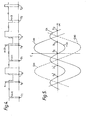
Ensuite, si le système de la demande citée est bien adapté à un moteur pas à pas dont les pôles du stator sont séparés par un entrefer, il l'est beaucoup moins à un moteur dit à zones saturables dont les pôles se rejoignent par des isthmes de faible largeur. La figure 1 du présent exposé montre schématiquement un moteur dont les pôles du stator sont séparés par des entrefers 1. Dans ce cas, tout le flux JSab issu du rotor aimanté 2 traverse le noyau de la bobine 3 pour produire aux bornes de cette bobine une tension induite Ui lorsque le rotor est en mouvement. Dans la demande EP 0 022 270, il est prévu de mesurer la tension induite Ui immédiatement après la fin de l'impulsion motrice, la bobine étant mise en circuit ouvert. Si le moteur à entrefers reçoit une impulsion de polarité correcte, la tension Ui recueillie aux bornes de sa bobine sera d'une amplitude suffisamment élevée pour décider qu'on doit continuer à l'alimenter avec des impulsions de faible largeur. Il en va autrement si l'on applique le système décrit dans la demande citée à un moteur à zones saturables. La figure 2 montre schématiquement un tel moteur où les pôles du stator sont réunis par des isthmes 4. Dans ce cas, on voit que le flux créé par l'aimant se partage en un flux if passant par les isthmes et en un flux φab passant par le noyau de la bobine. Il ressort de ceci que si l'on applique le système de la demande citée (c'est-à-dire qu'on mesure 1a tension Ui aux bornes d'unebobine mise à circuit ouvert) à un moteur à zones saturables, on recueillera une tension induite de faible amplitude, ce qui n'est évidemment pas favorable au bon fonctionnement de l'électronique de commande.Then, if the system of the cited request is well suited to a stepping motor whose poles of the stator are separated by an air gap, it is much less so to a motor known as with saturable zones whose poles are joined by isthmus narrow. Figure 1 of this presentation schematically shows a motor whose stator poles are separated by
Enfin, puisque la demande citée n'envisage une détection de tension induite qu'après les seules impulsions de faible largeur où on peut détecter une tension d'amplitude confortable, on ne sait rien du procédé qu'il faudrait mettre en oeuvre si l'on voulait détecter une tension encore suffisante produite après une impulsion de plus longue durée, tant il est vrai, comme cela apparaîtra par la suite, que la tension induite diminue rapidement lorsque l'impulsion de commande s'allonge.Finally, since the cited request envisages an induced voltage detection only after the only pulses of small width where it is possible to detect a voltage of comfortable amplitude, nothing is known of the process which should be implemented if the we wanted to detect a still sufficient voltage produced after a longer pulse, as it is true, as will appear later, that the induced voltage decreases rapidly when the control pulse is extended.
C'est le but de la présente invention de remédier aux inconvénients qui viennent d'être cités en proposant un procédé et un dispositif pour la mise en oeuvre de ce procédé qui apparaissent dans les revendications.It is the object of the present invention to remedy the drawbacks which have just been mentioned by proposing a method and a device for implementing this method which appear in the claims.
L'invention sera mieux comprise maintenant à la lumière de la description qui suit et pour l'intelligence de laquelle on se référera, à titre d'exemple, au dessin dans lequel :
- La figure 1 est une représentation schématique d'un moteur connu dont les pôles du stator sont séparés par des entrefers.
- La figure 2 est une représentation schématique d'un moteur connu dont les pôles du stator sont séparés par des isthmes.
- La figure 3 est un diagramme représentant les diverses impulsions appliquées au moteur selon une première variante de l'invention.
- La figure 4 est un diagramme représentant les diverses impulsions appliquées au moteur selon une seconde variante de l'invention.
- La figure 5 est un graphique représentant les couples mutuel et de positionnement du moteur en fonction de la position 0{ de son rotor.
- La figure 6 est un diagramme montrant comment est alimenté le moteur par des impulsions de sécurité selon l'invention.
- La figure 7 montre le dispositif permettant de mettre en oeuvre le procédé selon l'invention.
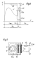
- La figure 8 est un graphique qui représente les diverses tensions que l'on trouve aux bornes de la bobine du moteur de même que le courant qui la traverse.
- La figure 9 est une représentation schématique d'un moteur dont les pôles du stator sont séparés par des isthmes auquel est appliqué le dispositif selon l'invention.
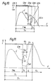
- La figure 10 est un graphique qui montre comment évolue l'amplitude de la tension induite quand l'impulsion motrice s'allonge.
- La figure 11 est un graphique qui montre comment on procède pour mesurer la tension induite quand l'impulsion de commande dépasse une durée déterminée.
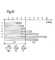
- La figure 12 est un diagramme illustrant les diverses durées d'impulsion qui se présentent dans l'alimentation du moteur selon l'invention.
- Figure 1 is a schematic representation of a known motor whose poles of the stator are separated by air gaps.
- Figure 2 is a schematic representation of a known motor whose poles of the stator are separated by isthmus.
- FIG. 3 is a diagram representing the various pulses applied to the motor according to a first variant of the invention.
- FIG. 4 is a diagram representing the various pulses applied to the motor according to a second variant of the invention.
- FIG. 5 is a graph showing the mutual and positioning torques of the motor as a function of the position 0 {of its rotor.
- FIG. 6 is a diagram showing how the motor is supplied with safety pulses according to the invention.
- Figure 7 shows the device for implementing the method according to the invention.
- Figure 8 is a graph showing the various voltages found across the motor coil as well as the current flowing through it.
- Figure 9 is a schematic representation of a motor whose poles of the stator are separated by isthmus to which the device according to the invention is applied.
- FIG. 10 is a graph which shows how the amplitude of the induced voltage changes when the driving pulse lengthens.
- FIG. 11 is a graph which shows how one proceeds to measure the induced voltage when the control pulse exceeds a determined duration.
- FIG. 12 is a diagram illustrating the various pulse durations which occur in the supply of the motor according to the invention.
On se reportera d'abord au diagramme de la figure 3 pour comprendre comment on procède pour asservir le moteur pas à pas selon une première variante de l'invention. Les impulsions référencées n - 2 à n + 4 sont les impulsions de commande que reçoit la bobine du moteur. Le début de chacune d'elles est séparé par un laps de temps constant, par exemple une seconde, ce qui fait progresser l'aiguille des secondes de la montre par pas de une seconde. Ce signal d'horloge provient de la sortie d'une chaîne de diviseurs de fréquence alimentée elle-même par un oscillateur formant base de temps selon une disposition désormais bien connue.We will first refer to the diagram in FIG. 3 to understand how we proceed to control the stepping motor according to a first variant of the invention. The pulses referenced n - 2 to n + 4 are the control pulses received by the motor coil. The start of each of them is separated by a constant period of time, for example one second, which advances the seconds hand of the watch in steps of one second. This clock signal comes from the output of a chain of frequency dividers which is itself supplied by a time base oscillator according to an arrangement which is now well known.
Dans les conditions de marche optimum, c'est-à-dire lorsque les évènements contraignants dont il a été parlé plus haut ne se présentent pas, le moteur travaille pratiquement à vide et une impulsion de très faible largeur Tl, telle celle représentée en n - 2 sur le diagramme, suffit à faire avancer normalement l'aiguille des secondes. On va supposer maintenant qu'après l'impulsion n - 2, à laquelle le moteur a encore répondu, le couple mécanique augmente subitement dû au concours conjugué de plusieurs événements contraignants. Le rotor ne réagira donc pas à l'impulsion n - 1 et lors de l'arrivée de 1a prochaine impulsion n, il ne réagira pas non plus puisque pour le faire progresser il lui faudrait recevoir à ce moment-là une impulsion de signe négatif. Ainsi, le rotor a perdu deux pas qu'il s'agit de rattraper. Selon l'idée déjà exprimée dans la demande EP 0 022 270, on envoie au moteur pour rattraper ce retard deux impulsions de rattrapage de grande largeur Ta un court laps de temps après la fin de l'impulsion n. Comme on le voit sur la figure 3, la première impulsion de rattrapage se présente dans le même sens que l'impulsion n-1 et la seconde dans le sens opposé de telle sorte que les impulsions de grande largeur Ta se substituent en quelque sorte aux impulsions de commande n - 1 et n de largeur Tl qui n'ont pas été à même de faire progresser le rotor du moteur. La durée Ta est choisie naturellement assez longue pour provoquer à coup sûr la progression du rotor dans les conditions de charge les plus défavorables. Le graphique de la figure 3 exagère cependant cette durée Ta par rapport à la durée Tl dans le but de bien faire ressortir le fonctionnement du système. L'invention présente l'originalité, par rapport à l'invention revendiquée dans la demande déjà citée, de ne pas poursuivre avec un train d'impulsions fixes de grande largeur sitôt après les impulsions de rattrapage, mais d'allonger quelque peu l'impulsion de commande de durée Tl en durée T2 et d'essayer si cette nouvelle impulsion pourrait être de durée suffisamment longue pour faire tourner le rotor. Si tel n'est pas le cas, on fait suivre les nouvelles impulsions n+1 et n + 2 de durée T2 par deux nouvelles impulsions de rattrapage de durée Ta comme cela est illustré en figure 3. A leur tour, les impulsions de rattrapage sont suivies par de nouvelles impulsions de commande n + 3, n + 4 de durée T3 légèrement supérieure à la durée T2. Si elles sont capables de mettre le moteur en rotation, on poursuit avec les impulsions de durée T3, sinon on envoie les impulsions de rattrapage pour procéder ensuite avec des impulsions de largeur T4 ou T3 < T4 et ainsi de suite.In optimum operating conditions, that is to say when the constraining events of which we have spoken above do not occur, the motor works practically at no load and a very small width pulse T l , such as that shown in n - 2 on the diagram, is enough to advance the second hand normally. We will now assume that after the impulse n - 2, to which the motor has responded again, the mechanical torque suddenly increases due to the combined effect of several constraining events. The rotor will therefore not react to impulse n - 1 and when the next impulse n arrives, it will not react either since to make it progress it would have to receive at this time a negative sign impulse . Thus, the rotor has lost two steps that need to be caught. According to the idea already expressed in the application EP 0 022 270, two very large catch-up pulses T are sent to the motor to make up for this delay at a short time after the end of the pulse n. As seen in Figure 3, the first catch-up pulse is in the same direction as the n-1 pulse and the second in the opposite direction so that the wide width pulses T a are somehow substituted to the control pulses n - 1 and n of width T l which were not able to advance the rotor of the motor. The duration T a is naturally chosen to be long enough to cause the rotor to progress under the most unfavorable load conditions. The graph in Figure 3 exaggerates however this duration T a compared to the duration T l in order to clearly highlight the functioning of the system. The invention has the originality, compared to the invention claimed in the application already cited, not to continue with a train of fixed pulses of large width immediately after the catching pulses, but to lengthen somewhat the control pulse of duration T l in duration T 2 and of trying if this new pulse could be of duration long enough to turn the rotor. If this is not the case, the new pulses n + 1 and n + 2 of duration T 2 are followed by two new catch-up pulses of duration T a as illustrated in FIG. 3. In turn, the pulses take-up are followed by new control pulses n + 3, n + 4 of duration T 3 slightly greater than the duration T 2 . If they are able to put the motor in rotation, we continue with the pulses of duration T 3 , otherwise we send the catch-up pulses to then proceed with pulses of width T 4 or T 3 <T 4 and so on.
Ainsi, le procédé qui vient d'être décrit montre qu'on adapte la durée des impulsions de commande à la charge imposée au moteur par niveaux successifs montants lorsque la charge augmente. Le procédé permet donc d'économiser de l'énergie et ceci dans des proportions encore plus importantes que si l'on n'avait à disposition que deux types d'impulsions seulement, comme cela était prévu dans la demande citée. Dans une réalisation particulière, on a choisi six impulsions différentes dont les durées motrices s'étendent de 3 à 9 ms par niveaux successifs montants de 0,5 ms pour les trois premières, de 1,5 ms pour les quatrième et cinquième et de 2 ms pour la sixième. Dans cette même réalisation, la durée de l'impulsion de rattrapage a été choisie à 8 ms. Ceci apparaîtra plus en détail lorsqu'on expliquera le diagramme représenté en figure 12.Thus, the process which has just been described shows that the duration of the control pulses is adapted to the load imposed on the motor by successive rising levels when the load increases. The process therefore makes it possible to save energy and this in even greater proportions than if only two types of pulses were available, as provided for in the cited application. In a particular embodiment, six different pulses have been chosen whose motor durations range from 3 to 9 ms in successive levels of 0.5 ms for the first three, 1.5 ms for the fourth and fifth and 2 ms for the sixth. In this same embodiment, the duration of the catch-up pulse was chosen at 8 ms. This will appear in more detail when the diagram shown in Figure 12 is explained.
On va supposer maintenant que, pour des impulsions n + 3, n + 4, etc., de durée T3, le moteur progresse normalement sans détection d'absence de pas. On peut penser qu'au bout d'une période prédéterminée les évènements contraignants qui avaient fait passer la durée des impulsions de Tl à T3 ont cessé. On va donc faire descendre la durée des impulsions de commande de T3 à T2. Si le résultat est satisfaisant pendant une même période prédéterminée, on pourra encore baisser d'un niveau et passer de la durée T2 à la durée Tl. Ladite période prédéterminée sera choisie à la suite d'observations qui auront été conduites sur la marche de la pièce d'horlogerie en fonction des diverses circonstances qui peuvent se présenter. Elle a été choisie dans la réalisation particulière dont il a été question plus haut à 512 secondes. En résumé, on adapte la durée des impulsions de commande à la charge imposée au moteur par niveaux successifs descendants lorsque la charge diminue.We will now assume that, for pulses n + 3, n + 4, etc., of duration T 3 , the motor progresses normally without detecting the absence of steps. One can think that at the end of a predetermined period the constraining events which had made pass the duration of the impulses from T l to T 3 stopped. We will therefore lower the duration of the control pulses from T 3 to T 2 . If the result is satisfactory during the same predetermined period, it will be possible to further decrease by one level and go from the duration T 2 to the duration T l . Said period predetermined will be chosen following observations that have been conducted on the running of the timepiece depending on the various circumstances that may arise. It was chosen in the particular realization which was mentioned above at 512 seconds. In summary, the duration of the control pulses is adapted to the load imposed on the motor by successive descending levels when the load decreases.
La figure 4 présente une seconde variante du procédé selon l'invention où, après l'envoi de deux impulsions de rattrapage, on alimente encore le moteur par une paire d'impulsions de même durée que celle qui existait avant la correction. Dans la figure, les impulsions de commande n + 1 et n + 2 ont la même durée Tl que celle des impulsions n - 1 et n. On peut penser en effet qu'en certaines circonstances les évènements contraignants ont un caractère fugitif tel qu'ils disparaissent très rapidement. Une tentative de réalimenter le moteur une seconde fois par des impulsions dont la durée n'a pas fait progresser son rotor une première fois peut être fructueuse.car,si la tentative aboutit, on aura évité une augmentation de consommation due à un élargissement inutile des impulsions de commande. Si la tentative n'aboutit pas, on alimente le moteur avec des impulsions de durée plus longue T2 après lui avoir envoyé les deux impulsions de rattrapage.FIG. 4 presents a second variant of the method according to the invention where, after sending two catch-up pulses, the motor is still supplied with a pair of pulses of the same duration as that which existed before the correction. In the figure, the control pulses n + 1 and n + 2 have the same duration T l as that of the pulses n - 1 and n. One might think, in fact, that in certain circumstances, binding events are of a fleeting nature such that they disappear very quickly. An attempt to refuel the motor a second time with pulses the duration of which did not advance its rotor the first time can be fruitful. For, if the attempt succeeds, an increase in consumption will have been avoided due to an unnecessary widening of the control pulses. If the attempt is unsuccessful, the motor is supplied with pulses of longer duration T 2 after having sent the two catch-up pulses.
Cette seconde variante n'est pas limitée à l'envoi renouvelé d'une seule paire d'impulsions de même durée Tl et on comprendra que des moyens peuvent être mis en oeuvre pour continuer à alimenter le moteur avec les impulsions Tl tant qu'un nombre donné d'impulsions de rattrapage n'aura pas été compté dans un intervalle prédéterminé. Ainsi, par exemple, on peut décider que si le rotor a manqué quatre fois son pas pendant 60 secondes, ces pas manqués ayant été suivis par quatre impulsions de rattrapage, on alimente alors le moteur par des impulsions de durée T2.This second variant is not limited to the renewed sending of a single pair of pulses of the same duration T l and it will be understood that means can be used to continue supplying the motor with the pulses T l as long as a given number of catch-up pulses will not have been counted in a predetermined interval. Thus, for example, it can be decided that if the rotor has missed its pitch four times for 60 seconds, these missed steps having been followed by four catch-up pulses, the motor is then supplied with pulses of duration T 2 .
Puisque dans le procédé décrit, on fait en sorte que la durée des impulsions de commande soit juste suffisante pour entraîner le mécanisme, on s'est rendu compte que dans certains cas, assez rares il est vrai, le rotor, après avoir démarré normalement à la suite d'une impulsion de polarité correcte, s'arrête après avoir parcouru un demi-pas seulement.Since in the process described, we make sure that the duration of the control pulses is just sufficient to drive the mechanism, we have realized that in some cases, quite rare it is true, the rotor, after starting normally at following a pulse of correct polarity, stops after having traveled only half a step.
La figure 5 montre l'évolution du couple de positionnement Ca et du couple mutuel Cab-tels qu'on les trouve dans un moteur pas à pas. Les positions angulaires S'2, S1 et S2 sont les positions d'équilibre stable du rotor et les positions I'1 et Il sont les positions d'équilibre instable de ce rotor. Normalement si le rotor franchit son pas en réponse à une impulsion positive, il passe de la position S1 à la position S2. Dans le cas particulier qui vient d'être évoqué, il se peut donc que le rotor s'arrête en position Il qui ne représente qu'une course d'un demi-pas. Bien que cette position soit instable, il est possible que le rotor s'y maintienne par les frottements qui agissent sur lui. Si avant que ne survienne la prochaine impulsion de commande une perturbation quelconque est appliquée à la montre, le rotor soit reculera en position Sl, soit avancera en position 52. Dans le premier cas, la nouvelle impulsion de commande présentera une polarité incorrecte et les impulsions de rattrapage Ta feront rattraper les deux pas perdus. Dans le second cas, le rotor aura rat- trappé lui-même le pas perdu et aucune impulsion de rattrapage ne lui sera envoyée. La situation se présente différemment si le rotor reste fixé sur la position Il quand survient la prochaine impulsion. En effet, cette prochaine impulsion négative développe le couple mutuel -Cab qui se trouve être dans le même sens que le couple négatif de positionnement -Ca. Si le couple -Cab est très élevé, il est possible alors que, conjugué au couple -Ca, il développe assez d'énergie pour déplacer le rotor de la position Il à la position S'2 sans s'arrêter à la position S1, ce déplacement s'opérant sans qu'il y ait eu détection de polarité incorrecte. Le rotor se fixe de façon stable en position S'2. A partir de ce moment-là, la prochaine impulsion, dirigée dans le sens positif, développera le couple mutuel Cab dessiné en traits interrompus et le rotor progressera normalement. On tire de ce raisonnement que le rotor a perdu définitivement deux pas qu'il ne sera pas possible de rattraper.FIG. 5 shows the evolution of the positioning torque Ca and of the mutual torque Cab-such as they are found in a stepping motor. The angular positions S ' 2 , S 1 and S 2 are the stable equilibrium positions of the rotor and the positions I' 1 and Il are the unstable equilibrium positions of this rotor. Normally if the rotor takes its step in response to a positive impulse, it goes from position S 1 to position S 2 . In the particular case which has just been mentioned, it is therefore possible for the rotor to stop in position II, which represents only a half-step stroke. Although this position is unstable, it is possible that the rotor is maintained there by the friction which acts on it. If before the next command pulse occurs any disturbance is applied to the watch, the rotor will either move back to position S l or move to
La figure 6 montre un arrangement qui palie l'inconvénient cité en proposant selon l'invention d'envoyer à la bobine du moteur un laps de temps prédéterminé après la fin de l'impulsion de commande de durée Tt, une impulsion de sécurité de durée Ts. Si l'on se reporte de nouveau à la figure 5, on comprendra que,si le rotor est bloqué en position I1, il suffira d'une impulsion de durée très courte pour le faire parvenir soit en S1 soit en S2. Une impulsion de sécurité négative le ramènera en S1 et la prochaine impulsion de commande normale se présentera comme incorrecte, ce qui déclenchera les deux impulsions de rattrapage comme cela a été expliqué plus haut. Une impulsion de sécurité positive amènera le rotor en S2; dans ce cas, la prochaine impulsion de commande se présentera comme correcte et aucun rattrapage n'aura lieu. Dans la pratique, on préférera une impulsion de sécurité négative car il faut moins d'énergie pour amener le rotor de la position Il à la position S1 que de la position Il à la position S2. Dans un exemple de réalisation de l'invention, on choisit pour Ts une durée comprise entre 0,2 et 0,5 ms et pour le laps de temps séparant la fin de l'impulsion de commande de l'impulsion de sécurité une durée de l'ordre de 50 ms.FIG. 6 shows an arrangement which overcomes the disadvantage cited by proposing according to the invention to send to the motor coil a predetermined period of time after the end of the duration control pulse Tt, a safety pulse of duration T s . Referring again to FIG. 5, it will be understood that, if the rotor is locked in position I 1 , a pulse of very short duration will suffice for the send either in S 1 or in S 2 . A negative safety pulse will bring it back to S 1 and the next normal command pulse will show up as incorrect, which will trigger the two catch-up pulses as explained above. A positive safety pulse will bring the rotor to S 2 ; in this case, the next command pulse will appear to be correct and no catch-up will take place. In practice, a negative safety pulse will be preferred since it takes less energy to bring the rotor from position Il to position S 1 than from position Il to position S 2 . In an exemplary embodiment of the invention, a duration between 0.2 and 0.5 ms is chosen for T s and for the period of time separating the end of the control pulse from the safety pulse a duration of the order of 50 ms.
On vient d'expliquer comment les diverses impulsions de commande sont arrangées les unes par rapport aux autres, comment leurs durées s'adaptent à la charge présentée par le mécanisme et comment il convient de rattraper les pas perdus. Ceci présuppose naturellement qu'on dispose de moyens pour détecter les pas qui n'ont pas été franchis. Dans la demande EP 0 022 270, on base cette détection sur la polarité de l'impulsion de commande par rapport à la position du rotor et, si le moteur est du type à entrefer, on mesure la tension induite Ui recueillie aux bornes de la bobine, cette dernière étant mise en circuit ouvert. Si le moteur reçoit une impulsion dirigée dans le bon sens, on mesure une tension induite Ui de grande amplitude alors que cette tension est nulle, voire négative si l'impulsion est dirigée dans le mauvais sens. On a exposé dans le préambule l'inconvénient qu'il y avait à mesurer cette tension à circuit ouvert pour un moteur qui présente des zones saturables puisque l'amplitude de ladite tension est relativement faible.We have just explained how the various control pulses are arranged with respect to each other, how their durations adapt to the load presented by the mechanism and how it is necessary to make up for lost steps. This naturally presupposes that we have means to detect the steps that have not been taken. In application EP 0 022 270, this detection is based on the polarity of the control pulse relative to the position of the rotor and, if the motor is of the air gap type, the induced voltage Ui collected at the terminals of the coil, the latter being placed in open circuit. If the motor receives a pulse directed in the right direction, a large amplitude induced voltage Ui is measured while this voltage is zero, or even negative if the pulse is directed in the wrong direction. We have explained in the preamble the drawback that there was in measuring this open circuit voltage for a motor which has saturable zones since the amplitude of said voltage is relatively low.
La figure 7 montre le dispositif mis en oeuvre pour obtenir une tension Ui très confortable même si le moteur est du type à zones saturables. Le schéma présenté ne se distingue de l'état de la technique que par l'adjonction d'une résistance 40 branchée en série avec la bobine 15 du moteur, résistance qui peut être court-circuitée lorsqu'on ferme l'interrupteur 35. Dans ce schéma, on trouve entre les bornes référencées 41 et 42 des impulsions de commande alternées d'amplitude U en provenance de la source d'alimentation continue Uplivrée par la pile lorsque les interrupteurs 31-32, respectivement 33-34 sont fermés. Si l'on définit par TRB la durée pendant laquelle la seule bobine 15 est branchée aux bornes 41 et 42, par Tx la durée pendant laquelle l'ensemble bobine 15 - résistance 40 est branché auxdites bornes et par Tcc la durée pendant laquelle la bobine 15 est mise en court-circuit, la séquence de commande des interrupteurs s'établit selon le tableau ci-après pour une impulsion positive :

Dans les techniques actuelles, se sont des transistors qui jouent le rôle des interrupteurs. Ils reçoivent leurs signaux d'un circuit de mise en forme classique.In current techniques, they are transistors which play the role of switches. They receive their signals from a conventional shaping circuit.
On se reportera maintenant à la figure 8 pour comprendre le rôle joué par la résistance additionnelle 40. Dans ce graphique, on a représenté en trait plein l'impulsion de commande U qu'on trouve aux bornes 41 et 42 (voir figure 7). Cette impulsion de commande est présente tant que les interrupteurs 31 et 32 sont fermés, c'est-à-dire pendant la période TRB et la période Tx (voir tableau ci-dessus). On désigne la durée de cette impulsion par Tn. Pendant la période TRB, la résistance 40 est court-circuitée et la bobine 15 reçoit une tension UB, représentée en traits interrompus, identique à la tension U si l'on fait abstraction de la faible chute de tension qui existe aux bornes de l'interrupteur 35. Cette tension UB est aussi à peu de chose près celle que l'on trouve aux bornes de la pile (Up). UB est la tension motrice seule utile à entraîner le rotor. Pendant la période Tx, la résistance 40 est branchée en série avec la bobine 15, l'interrupteur 35 est ouvert. C'est la période de mesure destinée à prélever aux bornes de la bobine la tension induite Ui développée par le moteur.We will now refer to FIG. 8 to understand the role played by the additional resistor 40. In this graph, we have shown in solid lines the control pulse U which is found at
La figure 9 représente le comportement du moteur pendant la période de mesure Tx. On s'y référera en même temps qu'aux figures 7 et 8. On l'a déjà dit, dès le début de la période Tx, la tension de commande U est appliquée aux bornes 41 et 42 du circuit qui comprend la bobine 3 et la résistance 40 connectées en série. On choisit la valeur de la résistance 40 de manière à engendrer dans la bobine 3 un courant LSAT qui, à son tour, va produire un flux φb suffisant pour saturer les isthmes 4 du stator. Dès l'instant où ces isthmes sont saturés, la quasi totalité du flux φab créé par l'aimant passe par le noyau de la bobine 3. Le flux Èab produit aux bornes de la bobine une tension induite
![]()
![]()
Comme on le verra plus loin, la méthode qui vient d'être décrite ne convient que pour des impulsions de commande dont la durée Tn est relativement courte. Ceci étant, on peut résumer ce qui vient d'être dit en affirmant que, pour des impulsions de commande dont la largeur est égale ou inférieure à la durée Tn, on branche une résistance en série avec la bobine du moteur pendant une période Tx située immédiatement avant la fin de l'impulsion de commande U et qu'on mesure durant ladite période Tx pendant un intervalle prédéterminé TUi la tension induite aux bornes de la bobine du moteur.As will be seen below, the method which has just been described is only suitable for control pulses whose duration T n is relatively short. That said, we can summarize what has just been said by asserting that, for control pulses whose width is equal to or less than the duration T n , a resistor is connected in series with the motor coil during a period T x located immediately before the end of the control pulse U and that during said period T x is measured during a predetermined interval T U i the voltage induced across the terminals of the motor coil.
Pour donner un exemple pratique, on choisit pour la période TRB la plus courte une durée de 3 ms et pour la période Tx une durée de 1 ms tandis que la valeur de la résistance 40 est de 15 kΩ pour une résistance de la bobine de 3 kt2.To give a practical example, we choose for the shortest period T RB a duration of 3 ms and for the period T x a duration of 1 ms while the value of the resistance 40 is 15 kΩ for a resistance of the
Si le procédé qui vient d'être décrit a spécialement été développé pour un moteur à zones saturables, il pourrait aussi être appliqué à un moteur à entrefers bien que cela pourrait être ressenti comme un luxe inutile puisqu'il suffit, comme on l'a dit, de mesurer pour ce dernier type de moteur la tension Ui immédiatement après la fin de l'impulsion Ug, la bobine étant disposée à circuit ouvert. Cependant l'universalité du procédé permettrait d'utiliser le même circuit électronique de commande pour les deux types de moteur, ce qui irait dans le sens d'une simplification et d'une diminution de prix de revient.If the process which has just been described has been specially developed for an engine with saturable zones, it could also be applied to an engine with air gaps although this could be felt as an unnecessary luxury since it suffices, as we have said, to measure for this latter type of motor the voltage Ui immediately after the end of the pulse Ug, the coil being arranged in open circuit. However, the universality of the process would make it possible to use the same electronic control circuit for the two types of engine, which would go in the direction of a simplification and a reduction in cost price.
On vient d'expliquer comment on mesure la tension induite Ui aux bornes de la bobine du moteur en saturant préalablement ses isthmes si l'on a affaire à un moteur à zones saturables. On a rappelé également l'enseignement de la demande EP 0 022 270 où cette tension induite est mesurée immédiatement après l'impulsion motrice, la bobine étant disposée à circuit ouvert. On a expliqué dans la demande citée que la tension Ui est égale à![]()
![]()
La figure 10 illustre le phénomène qui vient d'être expliqué et montre comment diminue l'amplitude de la tension Ui lorsque l'impulsion UB s'allonge. On constate qu'aux impulsions motrices de durée croissante UB1, UB2 et UB3 correspondent respectivement les tensions induites Uil, Ui2 et Ui3, le maximum desdites tensions se situant sur une enveloppe dont l'allure est représentative du facteur de couplage Cab/i, à la vitesse près. Pour l'impulsion UB4, la figure montre qu'aucune tension induite n'est détectée. Si l'on admet que la tension induite Ui3 suivant l'impulsion UB3 est déjà impropre à faire fonctionner correctement 1e circuit de réglage puisqu'elle présente une faible amplitude, il faudra avoir recours à un artifice qui permette une détection sûre pour toutes les impulsions de commande dont la largeur dépasse la durée limite Tn.FIG. 10 illustrates the phenomenon which has just been explained and shows how the amplitude of the voltage Ui decreases when the pulse U B lengthens. It can be seen that the driving pulses of increasing duration U B1 , U B2 and U B3 correspond respectively to the induced voltages Ui l , Ui 2 and Ui 3 , the maximum of said voltages being located on an envelope whose shape is representative of the factor of Cab / i coupling, to the nearest speed. For the pulse U B4 , the figure shows that no induced voltage is detected. If it is admitted that the induced voltage Ui 3 following the pulse U B3 is already unsuitable for making the regulation circuit work correctly since it has a low amplitude, it will be necessary to have recourse to a device which allows safe detection for all control pulses whose width exceeds the limit duration T n .
La figure 11 montre comment on procède selon l'invention pour palier l'inconvénient cité. Dans ce graphique, l'impulsion de commande U est composée de deux impulsions motrices UB et Uc séparées par une période Tx pendant laquelle on mesure la tension induite selon le procédé qui a été expliqué plus haut. Ainsi, si la largeur Tt de l'impulsion de commande U est supérieure à la durée Tn à partir de laquelle l'amplitude de la tension induite Ui serait insuffisante ou nulle, on mesure ladite tension induite Ui pendant un intervalle TUi compris dans la période Tx précédant immédiatement la fin de la période Tn. En d'autres termes, si la durée Tt de l'impulsion U nécessaire à faire progresser le rotor est trop longue pour qu'on puisse détecter une tension induite d'amplitude suffisante, comme cela a été expliqué plus haut, on ouvre une fenêtre dans ladite impulsion U et on mesure dans cette fenêtre la tension induite. Il va de soi que l'emplacement de cette fenêtre est choisi en un endroit où l'amplitude de la tension induite est encore importante. Cette fenêtre est réalisée en branchant une résistance en série avec la bobine pendant la période Tx (résistance 40 de la figure 7) s'il s'agit d'unmoteur à zones saturables (figure 2). Dans ce cas, la séquence de.commande des interrupteurs montrés en figure 7 s'établit selon le tableau ci-dessous :

La figure 12 illustre de façon exemplaire comment on adapte la largeur de l'impulsion de commande à la charge imposée au moteur et à quel moment on mesure la tension induite. Pour la construction donnée en exemple, il a été établi que cette tension induite est encore suffisante si on la mesure pendant une période Tx = 1 ms précédant immédiatement la fin de l'impulsion de commande dont la durée est égale ou inférieure à Tn = 5 ms. Du niveau 1 où la charge est la plus faible au niveau 3 où elle est légèrement plus élevée, la durée de l'impulsion de commande passe de 4 à 5 ms. La mesure de la tension induite se fait immédiatement avant la fin de l'impulsion de commande puisque la durée de ladite impulsion est égale (niveau 3) ou inférieure (niveaux 1 et 2) à la durée Tn. On voit que pour les mêmes niveaux, la durée TRB de l'impulsion motrice UB passe de 3 à 4 ms. A partir du niveau 4 adapté à une charge plus importante et jusqu'au niveau 6 correspondant à la charge maximum que peuvent présenter toutes les contraintes réunies ensemble, la durée de l'impulsion de commande passe de 6,5 à 10 ms. La mesure de la tension induite doit se faire dans une fenêtre Tx car, à partir du niveau 4, la largeur de l'impulsion de commande est supérieure à la durée prédéterminée Tn. Dans ces trois derniers niveaux, la fenêtre sépare les deux impulsions motrices UB et Uc dont la première est de durée constante TRB = 4 ms et dont la seconde Tc est de 1,5, 3 et 5 ms quand ont passe du niveau 4 au niveau 6. La figure 12 montre aussi l'impulsion de rattrapage de durée Ta dont la largeur est choisie à 8 ms.FIG. 12 illustrates in an exemplary manner how the width of the control pulse is adapted to the load imposed on the motor and when the induced voltage is measured. For the example construction, it has been established that this induced voltage is still sufficient if it is measured for a period T x = 1 ms immediately preceding the end of the control pulse whose duration is equal to or less than T n = 5 ms. From
L'invention qui vient d'être décrite poursuit le même but que celui qui a été expliqué dans la demande EP 0 022 270, à savoir proposer une méthode qui détecte un signal de tension induite de grande amplitude lorsque la bobine du moteur reçoit une impulsion de polarité correcte. Cette méthode conduit à un fonctionnement très sûr du système d'asservissement qui répond par oui ou non, comme c'est le cas dans un système logique.The invention which has just been described pursues the same aim as that which was explained in application EP 0 022 270, namely to propose a method which detects a signal of induced voltage of large amplitude when the motor coil receives a pulse. of correct polarity. This method leads to a very safe operation of the servo system which responds with yes or no, as is the case in a logic system.
Par ailleurs, comme cela a été exposé à propos de la demande citée, la tension Ui est comparée à une tension de référence dans un comparateur. Si Ui est plus grand que ladite référence, c'est une impulsion de polarité correcte qui a été envoyée au moteur et il n'ap- parait aucun signal à la sortie du comparateur. Le circuit de commande continue à envoyer des impulsions de même durée. Si, au contraire, Ui est plus petit que la référence, c'est une impulsion de polarité incorrecte qui a été envoyée au moteur et il apparaît un signal à la sortie du comparateur qui oblige le circuit de commande à envoyer deux impulsions de rattrapage puis un train d'impulsions de commande, comme cela a été expliqué ci-dessus.Furthermore, as has been explained with respect to the cited request, the voltage Ui is compared with a reference voltage in a comparator. If Ui is greater than said reference, a pulse of correct polarity has been sent to the motor and there is no signal at the output of the comparator. The control circuit continues to send pulses of the same duration. If, on the contrary, Ui is smaller than the reference, an incorrect polarity pulse has been sent to the motor and a signal appears at the output of the comparator which forces the control circuit to send two catching pulses then a control pulse train, as explained above.
Claims (9)
Applications Claiming Priority (2)
| Application Number | Priority Date | Filing Date | Title |
|---|---|---|---|
| CH2165/81 | 1981-03-31 | ||
| CH216581A CH644983GA3 (en) | 1981-03-31 | 1981-03-31 |
Publications (2)
| Publication Number | Publication Date |
|---|---|
| EP0062273A1 true EP0062273A1 (en) | 1982-10-13 |
| EP0062273B1 EP0062273B1 (en) | 1986-07-23 |
Family
ID=4227396
Family Applications (1)
| Application Number | Title | Priority Date | Filing Date |
|---|---|---|---|
| EP82102626A Expired EP0062273B1 (en) | 1981-03-31 | 1982-03-29 | Method of controlling a stepping motor |
Country Status (6)
| Country | Link |
|---|---|
| US (1) | US4456866A (en) |
| EP (1) | EP0062273B1 (en) |
| JP (1) | JPS57177296A (en) |
| CA (1) | CA1174060A (en) |
| CH (1) | CH644983GA3 (en) |
| DE (1) | DE3272080D1 (en) |
Cited By (3)
| Publication number | Priority date | Publication date | Assignee | Title |
|---|---|---|---|---|
| EP0108711A1 (en) * | 1982-10-13 | 1984-05-16 | Eta SA Fabriques d'Ebauches | Method and device for controlling a step motor |
| EP0182490A1 (en) * | 1984-10-16 | 1986-05-28 | Seiko Instruments Inc. | Improvements in or relating to stepping motor driven electronic timepieces |
| EP0679967A1 (en) * | 1993-01-18 | 1995-11-02 | Seiko Instruments Inc. | Electronic timepiece |
Families Citing this family (1)
| Publication number | Priority date | Publication date | Assignee | Title |
|---|---|---|---|---|
| JPS5980147A (en) * | 1982-10-29 | 1984-05-09 | Rhythm Watch Co Ltd | Small motor for timepiece |
Citations (5)
| Publication number | Priority date | Publication date | Assignee | Title |
|---|---|---|---|---|
| FR2388326A1 (en) * | 1977-04-23 | 1978-11-17 | Seiko Instr & Electronics | DEVICE FOR DETECTION OF CONDITIONS OF ROTATION OF THE MOTOR OF AN ELECTRONIC WATCH |
| US4158287A (en) * | 1976-08-12 | 1979-06-19 | Citizen Watch Company Limited | Driver circuit for electro-mechanical transducer |
| DE2854084A1 (en) * | 1977-12-20 | 1979-06-21 | Ebauches Electroniques Sa | ARRANGEMENT FOR FOLLOWING UP STEPS NOT TAKEN BY THE STEPPER MOTOR OF A TIMING DEVICE |
| FR2410843A1 (en) * | 1977-12-02 | 1979-06-29 | Seiko Instr & Electronics | ELECTRONIC WATCH |
| EP0022270A1 (en) * | 1979-07-09 | 1981-01-14 | Societe Suisse Pour L'industrie Horlogere Management Services S.A. | Position detector for a stepping motor |
Family Cites Families (1)
| Publication number | Priority date | Publication date | Assignee | Title |
|---|---|---|---|---|
| JPS5385467A (en) * | 1976-12-30 | 1978-07-27 | Seiko Epson Corp | Electronic wristwatch |
-
1981
- 1981-03-31 CH CH216581A patent/CH644983GA3/fr unknown
-
1982
- 1982-03-25 US US06/361,997 patent/US4456866A/en not_active Expired - Fee Related
- 1982-03-29 EP EP82102626A patent/EP0062273B1/en not_active Expired
- 1982-03-29 DE DE8282102626T patent/DE3272080D1/en not_active Expired
- 1982-03-30 CA CA000399806A patent/CA1174060A/en not_active Expired
- 1982-03-31 JP JP57054765A patent/JPS57177296A/en active Pending
Patent Citations (5)
| Publication number | Priority date | Publication date | Assignee | Title |
|---|---|---|---|---|
| US4158287A (en) * | 1976-08-12 | 1979-06-19 | Citizen Watch Company Limited | Driver circuit for electro-mechanical transducer |
| FR2388326A1 (en) * | 1977-04-23 | 1978-11-17 | Seiko Instr & Electronics | DEVICE FOR DETECTION OF CONDITIONS OF ROTATION OF THE MOTOR OF AN ELECTRONIC WATCH |
| FR2410843A1 (en) * | 1977-12-02 | 1979-06-29 | Seiko Instr & Electronics | ELECTRONIC WATCH |
| DE2854084A1 (en) * | 1977-12-20 | 1979-06-21 | Ebauches Electroniques Sa | ARRANGEMENT FOR FOLLOWING UP STEPS NOT TAKEN BY THE STEPPER MOTOR OF A TIMING DEVICE |
| EP0022270A1 (en) * | 1979-07-09 | 1981-01-14 | Societe Suisse Pour L'industrie Horlogere Management Services S.A. | Position detector for a stepping motor |
Non-Patent Citations (1)
| Title |
|---|
| 10e CONGRES INTERNATIONAL DE CHRONOMETRIE, no. 3, 11-14 Sept. 1979, Geneve, CH, M. UEDA et al.: "Adaptive controlled drive system of stepping motor for analog quartz watch", pages 67-72 * |
Cited By (6)
| Publication number | Priority date | Publication date | Assignee | Title |
|---|---|---|---|---|
| EP0108711A1 (en) * | 1982-10-13 | 1984-05-16 | Eta SA Fabriques d'Ebauches | Method and device for controlling a step motor |
| US4507599A (en) * | 1982-10-13 | 1985-03-26 | Eta S.A., Fabriques D'ebauches | Method and device for controlling a stepping motor |
| CH649187GA3 (en) * | 1982-10-13 | 1985-05-15 | ||
| EP0182490A1 (en) * | 1984-10-16 | 1986-05-28 | Seiko Instruments Inc. | Improvements in or relating to stepping motor driven electronic timepieces |
| EP0679967A1 (en) * | 1993-01-18 | 1995-11-02 | Seiko Instruments Inc. | Electronic timepiece |
| EP0679967A4 (en) * | 1993-01-18 | 1997-02-26 | Seiko Instr Inc | Electronic timepiece. |
Also Published As
| Publication number | Publication date |
|---|---|
| DE3272080D1 (en) | 1986-08-28 |
| US4456866A (en) | 1984-06-26 |
| JPS57177296A (en) | 1982-10-30 |
| EP0062273B1 (en) | 1986-07-23 |
| CH644983GA3 (en) | 1984-09-14 |
| CA1174060A (en) | 1984-09-11 |
Similar Documents
| Publication | Publication Date | Title |
|---|---|---|
| EP0679968B1 (en) | Timepiece driven by a mechanical power source and regulated by an electronic circuit | |
| EP0097350B1 (en) | Method of feeding a single phase stepping motor of a time piece | |
| EP0822470B1 (en) | Electronic timepiece comprising a generator driven by a barrel spring | |
| EP0171635B1 (en) | Method and apparatus to recognise the position of the rotor of a stepping motor | |
| EP0161582A1 (en) | Stepping motor assembly | |
| EP0060806B1 (en) | Method of reducing the power consumption of a stepping motor, and device for carrying out this method | |
| EP0062273B1 (en) | Method of controlling a stepping motor | |
| EP0443294B1 (en) | Method for feeding a monophase stepping motor | |
| EP0022270B1 (en) | Position detector for a stepping motor | |
| EP0077293B1 (en) | Process and device for controlling a stepping motor in a clock mechanism | |
| EP0024737B1 (en) | Detector for the movement of a stepping motor | |
| EP0253153B1 (en) | Method and device for controlling a stepping motor | |
| EP0087387B1 (en) | Method and means for controlling a bidirectional step-motor | |
| FR2478400A1 (en) | DEVICE FOR CONTROLLING AN ELECTRIC MOTOR | |
| EP0135104B1 (en) | Method and device for the control of a stepping motor | |
| EP0345224B1 (en) | Power supply method for a monophased stepping motor for a time piece | |
| EP0026002B1 (en) | Bipolar single-phase stepping motor with two directions of rotation | |
| EP0250862B1 (en) | Method and device for controlling a stepper motor | |
| FR2476409A1 (en) | CLUTCH PIECE WITH MOTOR CONTROL DEVICE STEP BY STEP | |
| EP0108711B1 (en) | Method and device for controlling a step motor | |
| EP0140089B1 (en) | Process for feeding a stepping motor | |
| EP0155661B1 (en) | Control circuit for a stepping motor | |
| EP0875807B1 (en) | Electronic timepiece powered by a generator driven by a mechanical energy source | |
| EP0190591A1 (en) | Motor assembly capable of functioning at a high speed | |
| EP0484770B1 (en) | Step by step motor control method and device for carrying out this method |
Legal Events
| Date | Code | Title | Description |
|---|---|---|---|
| PUAI | Public reference made under article 153(3) epc to a published international application that has entered the european phase |
Free format text: ORIGINAL CODE: 0009012 |
|
| AK | Designated contracting states |
Designated state(s): DE FR GB IT |
|
| 17P | Request for examination filed |
Effective date: 19830411 |
|
| RAP1 | Party data changed (applicant data changed or rights of an application transferred) |
Owner name: OMEGA SA |
|
| GRAA | (expected) grant |
Free format text: ORIGINAL CODE: 0009210 |
|
| AK | Designated contracting states |
Kind code of ref document: B1 Designated state(s): DE FR GB IT |
|
| PG25 | Lapsed in a contracting state [announced via postgrant information from national office to epo] |
Ref country code: IT Free format text: LAPSE BECAUSE OF FAILURE TO SUBMIT A TRANSLATION OF THE DESCRIPTION OR TO PAY THE FEE WITHIN THE PRESCRIBED TIME-LIMIT;WARNING: LAPSES OF ITALIAN PATENTS WITH EFFECTIVE DATE BEFORE 2007 MAY HAVE OCCURRED AT ANY TIME BEFORE 2007. THE CORRECT EFFECTIVE DATE MAY BE DIFFERENT FROM THE ONE RECORDED. Effective date: 19860723 |
|
| REF | Corresponds to: |
Ref document number: 3272080 Country of ref document: DE Date of ref document: 19860828 |
|
| PLBE | No opposition filed within time limit |
Free format text: ORIGINAL CODE: 0009261 |
|
| STAA | Information on the status of an ep patent application or granted ep patent |
Free format text: STATUS: NO OPPOSITION FILED WITHIN TIME LIMIT |
|
| 26N | No opposition filed | ||
| PGFP | Annual fee paid to national office [announced via postgrant information from national office to epo] |
Ref country code: GB Payment date: 19910225 Year of fee payment: 10 |
|
| PGFP | Annual fee paid to national office [announced via postgrant information from national office to epo] |
Ref country code: FR Payment date: 19910315 Year of fee payment: 10 |
|
| PGFP | Annual fee paid to national office [announced via postgrant information from national office to epo] |
Ref country code: DE Payment date: 19910321 Year of fee payment: 10 |
|
| PG25 | Lapsed in a contracting state [announced via postgrant information from national office to epo] |
Ref country code: GB Effective date: 19920329 |
|
| GBPC | Gb: european patent ceased through non-payment of renewal fee | ||
| PG25 | Lapsed in a contracting state [announced via postgrant information from national office to epo] |
Ref country code: FR Effective date: 19921130 |
|
| PG25 | Lapsed in a contracting state [announced via postgrant information from national office to epo] |
Ref country code: DE Effective date: 19921201 |
|
| REG | Reference to a national code |
Ref country code: FR Ref legal event code: ST |