EP0060068A1 - Remotely controlled lighting system - Google Patents
Remotely controlled lighting system Download PDFInfo
- Publication number
- EP0060068A1 EP0060068A1 EP82301043A EP82301043A EP0060068A1 EP 0060068 A1 EP0060068 A1 EP 0060068A1 EP 82301043 A EP82301043 A EP 82301043A EP 82301043 A EP82301043 A EP 82301043A EP 0060068 A1 EP0060068 A1 EP 0060068A1
- Authority
- EP
- European Patent Office
- Prior art keywords
- light
- light source
- color
- frame
- intensity
- Prior art date
- Legal status (The legal status is an assumption and is not a legal conclusion. Google has not performed a legal analysis and makes no representation as to the accuracy of the status listed.)
- Granted
Links
Images


Classifications
-
- F—MECHANICAL ENGINEERING; LIGHTING; HEATING; WEAPONS; BLASTING
- F21—LIGHTING
- F21V—FUNCTIONAL FEATURES OR DETAILS OF LIGHTING DEVICES OR SYSTEMS THEREOF; STRUCTURAL COMBINATIONS OF LIGHTING DEVICES WITH OTHER ARTICLES, NOT OTHERWISE PROVIDED FOR
- F21V29/00—Protecting lighting devices from thermal damage; Cooling or heating arrangements specially adapted for lighting devices or systems
- F21V29/50—Cooling arrangements
- F21V29/60—Cooling arrangements characterised by the use of a forced flow of gas, e.g. air
- F21V29/67—Cooling arrangements characterised by the use of a forced flow of gas, e.g. air characterised by the arrangement of fans
-
- F—MECHANICAL ENGINEERING; LIGHTING; HEATING; WEAPONS; BLASTING
- F21—LIGHTING
- F21S—NON-PORTABLE LIGHTING DEVICES; SYSTEMS THEREOF; VEHICLE LIGHTING DEVICES SPECIALLY ADAPTED FOR VEHICLE EXTERIORS
- F21S10/00—Lighting devices or systems producing a varying lighting effect
- F21S10/02—Lighting devices or systems producing a varying lighting effect changing colors
-
- F—MECHANICAL ENGINEERING; LIGHTING; HEATING; WEAPONS; BLASTING
- F21—LIGHTING
- F21S—NON-PORTABLE LIGHTING DEVICES; SYSTEMS THEREOF; VEHICLE LIGHTING DEVICES SPECIALLY ADAPTED FOR VEHICLE EXTERIORS
- F21S2/00—Systems of lighting devices, not provided for in main groups F21S4/00 - F21S10/00 or F21S19/00, e.g. of modular construction
-
- F—MECHANICAL ENGINEERING; LIGHTING; HEATING; WEAPONS; BLASTING
- F21—LIGHTING
- F21V—FUNCTIONAL FEATURES OR DETAILS OF LIGHTING DEVICES OR SYSTEMS THEREOF; STRUCTURAL COMBINATIONS OF LIGHTING DEVICES WITH OTHER ARTICLES, NOT OTHERWISE PROVIDED FOR
- F21V9/00—Elements for modifying spectral properties, polarisation or intensity of the light emitted, e.g. filters
- F21V9/40—Elements for modifying spectral properties, polarisation or intensity of the light emitted, e.g. filters with provision for controlling spectral properties, e.g. colour, or intensity
-
- G—PHYSICS
- G02—OPTICS
- G02B—OPTICAL ELEMENTS, SYSTEMS OR APPARATUS
- G02B26/00—Optical devices or arrangements for the control of light using movable or deformable optical elements
- G02B26/007—Optical devices or arrangements for the control of light using movable or deformable optical elements the movable or deformable optical element controlling the colour, i.e. a spectral characteristic, of the light
-
- H—ELECTRICITY
- H05—ELECTRIC TECHNIQUES NOT OTHERWISE PROVIDED FOR
- H05B—ELECTRIC HEATING; ELECTRIC LIGHT SOURCES NOT OTHERWISE PROVIDED FOR; CIRCUIT ARRANGEMENTS FOR ELECTRIC LIGHT SOURCES, IN GENERAL
- H05B47/00—Circuit arrangements for operating light sources in general, i.e. where the type of light source is not relevant
- H05B47/10—Controlling the light source
- H05B47/155—Coordinated control of two or more light sources
-
- F—MECHANICAL ENGINEERING; LIGHTING; HEATING; WEAPONS; BLASTING
- F21—LIGHTING
- F21V—FUNCTIONAL FEATURES OR DETAILS OF LIGHTING DEVICES OR SYSTEMS THEREOF; STRUCTURAL COMBINATIONS OF LIGHTING DEVICES WITH OTHER ARTICLES, NOT OTHERWISE PROVIDED FOR
- F21V11/00—Screens not covered by groups F21V1/00, F21V3/00, F21V7/00 or F21V9/00
- F21V11/16—Screens not covered by groups F21V1/00, F21V3/00, F21V7/00 or F21V9/00 using sheets without apertures, e.g. fixed
- F21V11/18—Screens not covered by groups F21V1/00, F21V3/00, F21V7/00 or F21V9/00 using sheets without apertures, e.g. fixed movable, e.g. flaps, slides
-
- F—MECHANICAL ENGINEERING; LIGHTING; HEATING; WEAPONS; BLASTING
- F21—LIGHTING
- F21V—FUNCTIONAL FEATURES OR DETAILS OF LIGHTING DEVICES OR SYSTEMS THEREOF; STRUCTURAL COMBINATIONS OF LIGHTING DEVICES WITH OTHER ARTICLES, NOT OTHERWISE PROVIDED FOR
- F21V14/00—Controlling the distribution of the light emitted by adjustment of elements
- F21V14/08—Controlling the distribution of the light emitted by adjustment of elements by movement of the screens or filters
-
- F—MECHANICAL ENGINEERING; LIGHTING; HEATING; WEAPONS; BLASTING
- F21—LIGHTING
- F21V—FUNCTIONAL FEATURES OR DETAILS OF LIGHTING DEVICES OR SYSTEMS THEREOF; STRUCTURAL COMBINATIONS OF LIGHTING DEVICES WITH OTHER ARTICLES, NOT OTHERWISE PROVIDED FOR
- F21V21/00—Supporting, suspending, or attaching arrangements for lighting devices; Hand grips
- F21V21/14—Adjustable mountings
- F21V21/30—Pivoted housings or frames
-
- F—MECHANICAL ENGINEERING; LIGHTING; HEATING; WEAPONS; BLASTING
- F21—LIGHTING
- F21V—FUNCTIONAL FEATURES OR DETAILS OF LIGHTING DEVICES OR SYSTEMS THEREOF; STRUCTURAL COMBINATIONS OF LIGHTING DEVICES WITH OTHER ARTICLES, NOT OTHERWISE PROVIDED FOR
- F21V29/00—Protecting lighting devices from thermal damage; Cooling or heating arrangements specially adapted for lighting devices or systems
- F21V29/50—Cooling arrangements
- F21V29/60—Cooling arrangements characterised by the use of a forced flow of gas, e.g. air
- F21V29/67—Cooling arrangements characterised by the use of a forced flow of gas, e.g. air characterised by the arrangement of fans
- F21V29/677—Cooling arrangements characterised by the use of a forced flow of gas, e.g. air characterised by the arrangement of fans the fans being used for discharging
-
- F—MECHANICAL ENGINEERING; LIGHTING; HEATING; WEAPONS; BLASTING
- F21—LIGHTING
- F21V—FUNCTIONAL FEATURES OR DETAILS OF LIGHTING DEVICES OR SYSTEMS THEREOF; STRUCTURAL COMBINATIONS OF LIGHTING DEVICES WITH OTHER ARTICLES, NOT OTHERWISE PROVIDED FOR
- F21V5/00—Refractors for light sources
- F21V5/04—Refractors for light sources of lens shape
-
- F—MECHANICAL ENGINEERING; LIGHTING; HEATING; WEAPONS; BLASTING
- F21—LIGHTING
- F21W—INDEXING SCHEME ASSOCIATED WITH SUBCLASSES F21K, F21L, F21S and F21V, RELATING TO USES OR APPLICATIONS OF LIGHTING DEVICES OR SYSTEMS
- F21W2131/00—Use or application of lighting devices or systems not provided for in codes F21W2102/00-F21W2121/00
- F21W2131/40—Lighting for industrial, commercial, recreational or military use
- F21W2131/406—Lighting for industrial, commercial, recreational or military use for theatres, stages or film studios
Definitions
- This invention relates to the illumination, in particular to the lighting of a stage or theatre.
- individual light sources are typically hung from trusses or fixed structural members mounted in front of the stage, at the sides of the stage or over the stage.
- the light sources are adjusted to direct the light beam to a desired location on the stage and are then secured in that position by tightening bolts or other fasteners.
- a large sealed beam lamp of 1,000 to 1,500 watts run from a 110 volt AC line is typically employed to create the light.
- such lamps generally noted as par lamps, generate a significant amount of infrared heat.
- the light sources are employed in either of two fashions. Certain light sources may be used as a wash or general stage illumination. The remainder of the light sources are used as spots for highlighting specific positions on the stage, such as an actor's face.
- the light beams emanating from each light source may be colored by the use of a colored celluloid gel.
- the gel is positioned within a frame which is slid into a receiver positioned at the end of the light source so that the beam passes through the colored gel.
- the gel functions to absorb the incident light other than the color desired. The absorbed light is transformed into heat which warps and discolors the gel, requiring frequent replacement as often as once every show.
- Shutters are typically pivoted at the end of the light source to block out selected portions of the light beam to shape the incidence of the beam on the stage.
- a mechanical iris may be provided in the light source to control the beam divergence.
- a light source is used as a wash, a wide beam divergence is desired.
- the light beam preferably is narrowed to a very small divergence.
- the intensity of the light beam emanating from each light source is individually controlled by a large power dimmer.
- the power dimmers are controlled by the main lighting control panel.
- the typical lighting system therefore requires a massive array of electrical cables, including cables connecting the control console with a power dimmer and cables interconnecting the power dimmer with the associated light source.
- the use of power dimmers to control the intensity of light has induced chop in the AC power line supplying the entire theater. This has been found to induce undesirable noise, such as distortion, hum etc. particularly during the performance of rock groups employing instruments relying on electrical input.
- a typical performance such as a rock concert or theatrical performance, may require a hundred or more individual lighting cues or lighting formats during the performance. Up to 500 separate lights may be necessary to light the entire performance. Usually 25% of these lights are used as wash and the remainder are used as specials. The large number of lights are necessitated as the light position, color, intensity and divergence must be preset prior to the performance.
- U.S. Patent No. 3,898,643 to Ettlinger, issued August 5, 1975 discloses a system including a memory for storing the intensity level of the lights for each cue during a performance. The system may then set the intensity of the light through conventional power dimmers in an automatic sequence. However, this device merely transfers the manual operation of power dimmers to an automatic system which, while relieving an operator of substantial work during the performance, necessitates still more complex and costly equipment in the system.
- a lighting system which includes at least one light source for producing a directable beam of light mounted for pivotal motion. Pivoting mechanisms are provided for pivoting the light source to a preselected position.
- a controller is provided for input of a coded address representing a selected one of the light sources and data representing the preselected position of the light source.
- a Transmitter is provided for transmitting the coded address and data to a receiver. The receiver is provided for reading the coded address, identifying the light source corresponding to the coded address and reading the positioning data and activating the pivoting mechanism of the selected one of the light sources to pivot the light source to the preselected position.
- a light source for producing a directable beam of light includes a frame and a lamp for producing light positioned within the frame. At least one dichroic filter is pivotally mounted within the frame for pivotal motion into the light path for transmitting light of a preselected color, the angle of incidence of the light on the dichroic filter being variable to alter the color transmitted as the dichroic filter is pivoted.
- a light source for producing a directable beam of light which includes a frame and a lamp for producing a light position within the frame.
- a color wheel is rotatably mounted on the frame and has at least one dichroic filter mounted in the periphery thereof, the wheel being rotatable to position the dichroic filter across the light path transmitting a preselected color.
- a lighting system for use in lighting an area.
- the lighting system includes at least one light source for producing a directable beam of light, each of the light sources having a mechanism to position the light source, and a mechanism to vary the color of the beam of light produced.
- a controller is provided for inputing information representing the desired position and color of a selected one of the light sources.
- a transmitter is provided for transmitting the input information and a receiver is provided associated with the selected one of the light sources for activating the mechanisms controlling the position and color of the selected one of the light sources to correspond to the information transmitted.
- Mechanisms to vary the intensity and divergence of the light beam produced may also be provided and the input information contains data representing the desired setting of these functions.
- FIGURE 1 illustrates a lighting system 10 forming the present invention.
- the lighting system 10 may be used to light a stage or other forum where directable light is desired.
- the lighting system 10 may be used to light a rock concert or a theatrical performance.
- the lighting system 10 includes a remote control panel 12 for controlling the light sources 14 mounted on a truss 16 above, in front or to the side of the stage to be lit.
- Each light source 14 may be positioned and the light beam produced thereby varied in color, intensity and beam divergence from the remote control panel 12.
- the remote control panel 12 includes a memory for recalling the position, color, intensity and beam divergence of each light source 14 for each separate cue and the remote control panel 12 will automatically set up an entire cue by the activation of a single control on the control panel 12.
- Each function described above is accomplished with only a single two conductor data link or signal cable 18 interconnecting the control panel 12 and truss 16 and a power cable 20.
- the first embodiment of light source 14 is illustrated in FIGURES 2a and 2b as light 30.
- the light 30 includes a rigid frame 32 having an aperture 34 formed in one end thereof for passage of the light beam 36.
- the frame 32 and components therein are pivotally mounted to the truss 16 by a gimbal mechanism 38.
- the gimbal mechanism 38 pivotally supports the frame 32 for motion in two mutually perpendicular planes.
- the frame 32 may move in a horizontal plane or pan across a stage and in a vertical plane or tilt.
- the gimbal mechanism 38 also includes motor for independently panning and tilting the frame 32 in discrete increments in response to signals generated by the remote control panel 12.
- the motors permit the light beam 36 to be aimed at any desired location on the stage.
- servo motors are used in gimbal mechanism 38.
- a lamp 50 is positioned within frame 32 adjacent one end thereof.
- the lamp 50 produces white light, or light across substantially the entire visible spectrum.
- the lamp 50 may comprise a common projection lamp as used in movie projectors and the like having a 110 volt AC input with a power consumption of approximately 350 watts. This type of lamp has the advantage of very low infrared radiation generation, thereby avoiding the generation of excess heat within the light 30.
- An elliptic mirror 52 is positioned about the lamp 50 to reflect light incident thereon to converge at a focus 54 within the frame 32. After convergence at focus 54, the light diverges and enters a collimating lens 56 which collimates light incident thereon to form the light beam 36.
- Dichroic filters 58 and 60 are pivotally mounted to the frame 32 on either side of focus 54.
- Two additional dichroic filters 62 and 64 are pivotally mounted to frame 32 on the side of collimating lens 56 opposite focus 54.
- Dichroic filters are available commercially, such as those sold by the Technical Products Division of Optical Coating Laboratory, Inc. of P.O. Box 1599, Santa Rosa, California.
- a dichroic filter is a multiple layered optical film having a glass, pyrex or quartz base. The alternate layers have low and high indexes of refraction, respectively.
- Dichroic filters work on an interference principle, separating two colors out of a white light source, one color being transmitted and the other color, the complement of that transmitted, being reflected.
- the transmitted color depends upon the type of material used in the layers and its refractive index, the thickness of each layer, the number of layers and the angle of incidence of the white light source striking the surface of the filter. By varying the angle of incidence of white light on a given filter, a preselected range of color spectrum may be produced.
- the dichroic filters 58-64 are preferably formed of multiple thin layers of material and may have a circular, rectangular or other shape. The filters therefore have a thickness of a relatively small dimension and a relatively large surface for incidence of light.
- Dichroic filter 58 is mounted for pivotal motion about an axis X-X by shaft 66. As can be seen with reference to - 2b, the axis X-X extends through the center of the light path.
- Dichroic filters 60, 62 and 64 are similarly mounted for pivotal motion about axis Y-Y, Z-Z and V-V, respectively, about shafts 68, 70 and 72, respectively. Each dichroic filter may be pivoted about its associated shaft by means of a servo motor 74, 76, 78 or 80.
- the dichroic filters When the dichroic filters are aligned with the light path, as shown in FIGURE 2b, no influence on the color is created and the filters do not significantly interfere with the light path. Therefore, a white light beam is created for use as a spot or other desired use.
- a given dichroic filter As a given dichroic filter is pivoted so that the angle of incidence of the light, e, increases above 0, the filter moves across the light path and transmits a colored beam with the color dependent on the angle e.
- the four filters may be chosen to transmit four dominant colors. Filter 58 may transmit blue, filter 60 green, filter 62 red and filter 64 yellow. However, each individual filter will transmit a range of spectrum as e is varied.
- the blue and green filters are positioned furthest from lamp 50 to form dichroic filters 62 and 64. This permits desirable pastel or unsaturated shades of color to be produced when low values of e are present.
- the permutations of color in the light beam 36 in passing light through a filter or multiple filters are theoretically infinite dependent only on the relative position of the filters. In one application of the present invention, 4,000 permutations of color are possible.
- a douser unit 90 is positioned within the frame 32.
- the douser unit 90 acts to permit the light beam 36 to pass therethrough when open but substantially cuts off the light beam 36 when closed. It therefore acts like a shutter to block light from passing from the light 30, but permits the light beam to be almost instantaneously restored by opening the douser unit.
- the douser unit 90 is in the form of a mechanical shutter.
- the shutter is controlled by a solenoid 92 which may be activated to either close or open the shutter to control the light beam.
- the shutter is designed so that the shutter is closed upon deactivation of the solenoid. This feature prevents a light beam from emenating from a light when the light is malfunctioning, or the data transmitted to the light is in error to prevent improper lighting.
- a dimmer unit 94 In close proximity with douser unit 90 is a dimmer unit 94.
- the dimmer unit 94 dims or decreases the intensity of light beam 36 to vary the mood or impact of the light on the stage.
- the dimmer unit 94 is controlled by a servo motor 96.
- An integrating lens 100 is provided to mix the light passing through the dichroic filters to insure a uniform color.
- the integrating lens 100 is formed of a large number of small spherical lens 102 mounted on a flat transparent surface which acts to homogenize any light passing therethrough.
- light beam 36 passes through a focusing lens 104 prior to exiting frame 32 through aperture 34 to light a desired location on a stage.
- the light 30 may include a cooling fan 106 mounted in the lower base thereof.
- the cooling fan 106 forces outside air into the lower portion of the light to cool the electric components such as receiver 166 and servo drive 168.
- a portion of the airflow is directed through nozzles 107 at the lamp 50 to cool the lamp directly.
- the remainder of the air passes forward to a slot 108 adjacent the douser and dimmer units and passes to the upper portion of the light 30 to cool the lenses and dichroic filters.
- the air passing through slot 108 and issuing from the nozzles 107 exits the light 30 through a grating 109 at the rear of light 30 adjacent the elliptic mirror 52.
- the second embodiment of the light source 14 is illustrated in FIGURES 3-5 and comprises light 110. Certain portions of light 110 are identical to portions of the light 30. These portions are identified by reference numerals indicating the identical portion in light 30 with a superscript '.
- the frame 32' is also gimbaled on a gimbal mechanism 38'.
- the mechanism 38' permits the frame 32' and light beam 36' emenating therefrom to be panned and tilted across a stage.
- the lamp 50' produces white light which is reflected off the eliptical mirror 52' to converge at a focus 54' within the frame 32' of the light 110.
- Color wheels 112 and l14 are rotatably mounted to frame 32' for rotation about axes R-R and S-S.
- the axes R-R and S-S are generally aligned with the path of light travel in the light 110 and are positioned so that the light falls on portions of the outer periphery of both color wheels 112 and 114, as best illustrated in FIGURE 4.
- Each color wheel 112 and 114 has a plurality of apertures numbered from 1 to n distributed about the outer periphery of the wheel. Each aperture may be centered across the light path. The color wheels 112 and 114 are positioned sufficiently close to the focus 54' so that substantially all the light from lamp 50' passes through the aperture centered on the path of the light and the area of the apertures may be minimized.
- each wheel l12 and 114 is clear to permit passage of the light therethrough without interference. However, the remainder of the apertures have individual dichroic filters mounted therein, each filter permitting a single color to be transmitted therethrough.
- Each color wheel may include sufficient dichroic filters to individually provide a wide spectrum of color or, in combination with the other color wheel, provide a number of color permutations.
- each color wheel 112 and l14 will have 32 apertures, one being clear and 31 having dichroic filters mounted therein. This permits almost 1000 permutations of color to be induced in the light beam 36' issuing from light 110 by rotating the two color wheels 112 and l14 by motor means 116 and 118, respectively.
- a gobo wheel 126 is rotatably mounted on frame 32' for rotation about axis T-T.
- the gobo wheel 126 has apertures 128a-d formed in the outer periphery thereof through which substantially all the light diverging from focus 54' may pass therethrough when an aperture is centered across the light path. Again, aperture 128a does not interfere with the light travel.
- the apertures 128b-d may have characters or other designs meant to project a silhouette or other background design onto the stage.
- a motor means such as servo motor 129 is used to rotate the gobo wheel 126 to position an aperture across the beam.
- a light intensity wheel 130 is rotatably mounted to frame 32' for rotation about an axis U-U.
- the outer periphery of intensity wheel 130 is formed of a material permitting a percentage of light incident thereon to be transmitted therethrough which varies as a linear function of the angle ⁇ measured from a reference radius r.
- the wheel 130 may be a transparent wheel with a reflective coating around the periphery that varies in reflectance from 0% to approximately 100%. This type of wheel is referred to as a circular variable neutral density wheel.
- Such a wheel is sold by Melles Griot, 1770 Kettering St., Irvine, California as a Circular Linear-Wedge N-D Filter.
- the periphery is sized to permit the entire light beam to be incident thereon.
- Portion 132a does not interfere with light passage therethrough. Portions 132b-h have progressively smaller percentages of incident light being transmitted therethrough and reflecting higher percentages of the incident light diverging from focus 54' back into the light.
- the wheel 130 has been divided into 7 portions 132a-b merely for ease of discussion.
- the variation of ⁇ permits the light transmitted to be varied continuously from virtually 100% to 0% of the incident light.
- the wheel 130 in portion 132h permits no light to be transmitted therethrough, forming an effective means to cut off the light beam 36'.
- a servo motor 133 is used to rotate a desired portion across the light path.
- light intensity wheel 130 may include a number of apertures formed in the outer periphery thereof. Each aperture is sized to permit the entire light beam to pass therethrough. Reflective mirrors are mounted in each of the apertures. The mirrors 132'a-h distributed about the wheel 130' have progressively smaller percentages of incident light being transmitted therethrough and reflect higher percentages of the incident light diverging from focus 54' back into the light. A servo motor may be used to rotate the intensity wheel 130 to position a mirror having a desired percentage of transmission across the light beam. Preferably, one mirror transmits substantially 100% of the light incident thereon to provide a full intensity light beam.
- a mechanical iris 135 would be mounted adjacent the lens 138 on either side thereof as illustrated in FIGURE 3 in phantom line.
- the mechanical iris 135 would be controlled by a servo motor 137 which would operate to extend or contract the iris to vary the intensity of the light beam emanating from light 110.
- a three element zoom lens 134 is positioned within the frame 32' for controlling the divergence of the light beam 36' issuing from the light 110.
- the three element lens includes a movable center lens 136 positioned between fixed outer lens 138 and 140.
- the zoom lens assembly 134 will permit variation of the beam divergence from an angle of 5 degrees to an angle of 50 degrees as illustrated in FIGURE 3.
- the movement of the center element 136 is controlled by a servo motor 142.
- both lights 30 and 110 permit variation of the position, color, and intensity of a light beam.
- Light 110 also permits variation of the beam divergence. These functions may be remotely controlled in a manner described hereinafter.
- the lights 30 and 110 are a significant improvement over the prior art lights.
- the dichroic filters mounted therein for inducing color in the light beams permit a large number of permutations of shades and hues to be created, thereby amplifying the artistic scope available to the director.
- the dichroic filters transmit light incident thereon and reflect the complement of the color of the transmitted beam. Therefore, no light is absorbed and transformed to heat as found in the prior art use of celluloid gels.
- the use of a relatively low power projection lamp in lights 30 and 110 substantially reduces the generation of infrared radiation which causes high power consumption and heat buildup within prior art devices.
- FIGURE 7 A flow chart of the light system 10 is shown in FIGURE 7.
- Information representing the desired position, color, intensity and beam divergence of a light source 14 is manually entered by an operator or stored in a memory in the controller 160.
- Each individual light source is identified by a code in address 162. This code identifies the particular light or series of lights to which a set of variable functions is assigned.
- the information input to controller 160 is placed in a 32 bit parallel format and transferred to a transmitter 164. While a 32 bit data format is suitable for the system 10, it will be understood that the data format would be expendable or contractable as needed to achieve a desired control resolution.
- the selected light source is represented in address 162 by 8 bits of parallel data which is transferred into transmitter 164.
- Transmitter 164 translates the parallel data into a 40 bit serial format for transmission along a two conductor twisted signal cable 18.
- the signal cable 18 may comprise common microphone cable.
- the first 8 bits of the serial data transmitted represents the address of the light source.
- Signal cable 18 represents an open loop system, having receivers 166 branched therefrom associated with each of the light sources 14. Each receiver 166 translates the first 8 bits of serial data to identify the particular light source represented by the data in address 167.
- the address select 167 includes a number of thumb operated switches for determining the address of the particular light source. If a light source mounted on the truss is rendered inoperable, the light source may be rapidly replaced with a new light source by setting the address of the new light source to correspond with the address of the failed light source. If the associated light source corresponds to the address in the data transmitted, the remaining 32 bits of data are transferred to servo drives 168 and translated from digital information to analog information for controlling the pan and tilt, color, intensity and beam divergence of the light sources. In the embodiment illustrated in FIGURE 7, four dichroic filters having the dominant colors, red, blue, green and yellow are employed represented by the letters R, B, G and Y.
- the manual input by an operator of the information representing the position, color, intensity and beam divergence of the light system 10 is best discussed with reference to the control panel 12 illustrated in FIGURE 6.
- the control panel 12 illustrated in FIGURE 6 is designed to control 32 separate light sources such as lights 30 represented by the 32 keys in the direct assign group 182.
- the operator may address any one of the 32 light sources by depressing its associated key or a number of the light sources by sequentially depressing the key representing each of the light sources.
- the position of the selected light source or sources may be adjusted in unison by rotating the pan and tilt controls 184 and 186.
- the pan and tilt controls activate the gimble mechanism 38 associated with a light 30.
- Color controls 188, 190, 192 and 194 are provided for adjusting the angle e of each of the four dichroic filters 58, 60, 62 and 64.
- the color controls 188-194 will be replaced by two 32 position switches or other means for rotating the desired aperture of the two color wheels 112 and 114 across the path of the light beam.
- the intensity control 195 may be used to control the intensity of the light beam from light 30 if a mechanism is provided on the light to do so.
- control panel 12 is adapted for use with the light 110, the intensity control 175 would rotate the intensity wheel 130 to adjust the intensity of the light beam as desired.
- the zoom control 196 is inactive when control panel 12 is associated with lamp 30.
- the zoom control may be used to adjust the position of the traveling lens 136.
- a color memory 198 may be provided which associates individual colors with the keys numbered 1 through 16.
- the color controls 188, 190, 192 and 194 may be adjusted to create a blue light beam.
- a selected button such as 4
- the setting of the filters to provide a blue light beam will be stored within the memory.
- the setting may be recalled by merely depressing the key 4 in color memory 198. This permits the operator to preprogram common colors so that one button operation will set a light to the desired color and avoid the necessity to address four controls for each color setting.
- a concert or performance being lit typically has a number of light cues.
- the independent control of the variable functions in a light source 14 within the light system 10 permits a single light source to be used in a different position, and with a different color, intensity and beam divergence for each cue.
- the cue control 200 is used to assign the information input regarding position, color, intensity and beam divergence to a particular cue.
- the cue selected is displayed on a display 202.
- this information may be stored in a memory by depressing the store key S in cue control 200.
- the information stored may be recalled at any desired moment.
- cross fade controls 206 and 208 When the handle 210 of cross fade control 206 is moved adjacent the display 214, the light system 10 automatically recalls the information regarding each light source and activates the servo drives 168 to position the light sources, adjust the colors, intensities and beam divergences to the value set for the cue displayed in display 214.
- the light system 10 recalls the information regarding each light source for the cue displayed in display 216 and activates the servo drives 168 to set the light sources for the cue displayed in display 216.
- the display 216 is typically set to zero and the display 214 is set to one. With the handles 210 and 212 in the position shown adjacent display 216, no stage lighting is provided. Both handles 210 and 212 are moved upward adjacent display 214, thereby setting the light sources for cue I and increasing the intensity of the lights to their full value when the handles abut display 214. The display 216 automatically resets to cue 2. At the end of the scene representing cue 1, the handles 210 and 212 are moved downward adjacent display 216 to fade out the settings of cue 1 and fade in the settings of cue 2.
- the cue control 220 may be activated to set a desired cue in either display 214 or display 216, the display elected being opposite the present position of the cross fade handles 210 and 212 so that the desired cue may be faded in by moving the handles toward the selected display.
- the cue control 220 is activated to elect a cue out of sequence by depressing the E key and depressing the keys corresponding to the desired cue.
- a blackout - button 221 is provided for instantaneously darkening the stage by blocking the light beam from every light source.
- a grand master dimming control 222 is provided for reducing the lighting intensity from the value for a given cue to a total blackout.
- a number of preset lighting cues may be desired.
- a general stage wash or other lighting setup may be commonly employed.
- Such a preselected cue may be stored in control panel 12 and recalled by depressing a key on either upper or lower cue controls 218 and 220. If, for example, a general wash cue has been preprogrammed into upper cue control 218 for recall by depressing key 5, the depression of key 5 will cause a letter P, representing preselected and the number 5 to appear in display 214 and the preset cue will be implemented as the cross fade handles 210 and 212 are moved adjacent display 214.
- a preselected cue may be recalled from lower cue control 220 by depressing the associated key, which will cause the letter P and associated key number to be displayed in display 216 and implement the cue as the cross fade handles 210 and 212 are moved adjacent display 216.
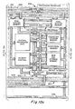
- FIGURE 9 A general schematic of the control panel 12 of the present invention is disclosed in FIGURE 9.
- the manual controls 350 represent the various switches, buttons, visual displays and sliding controls such as illustrated in FIGURE 6.
- the manual controls 350 are interconnected by a bus 352 to a control interface 354.
- the control interface 354 continuously scans the setting of the manual controls 350 and communicates through a data bus 356 to the control processor 358.
- the control panel 12 operates in two separate modes.
- the program mode information is input by the manual control 350 representing the desired position, color, divergence and intensity of the lights 14 for each cue during the show.
- the control processor 358 is responsible for recalling the settings of the variable functions from various memories within the control panel and directing the remainder of the control panel to set each light 14 with the proper setting for each cue in sequential order when requested by the operator through the manual controls 350.
- the control processor 358 will direct information representing the desired setting for a variable function to one of the five variable function processors.
- the panning function includes a data bus 360 interconnecting the control processor 358 and a processor interface 362.
- a bus 382 interconnects the processor interface362 with the pan function processor 384.
- a pan cue memory 386 is interconnected with the pan function processor 384 by a data bus 388.
- Information input to the control processor 358 regarding the panning function will be transmitted along the bus 360, through processor interface 362 and into pan function processor 384 through bus 382.
- the control processor 358 may direct the pan function processor 384 to store the information in the pan cue memory 386.
- Similar bus lines 364, 370, 374 and 378 interconnect the control processor 358 with processor interfaces 368, 372, 376 and 380.
- the processor interfaces 368, 372, 376 and 380 are interconnected through bus lines 390, 398, 406 and 412 to the tilt function processor 392, intensity function processor 400, color function processor 408 and zoon function processor 414.
- the tilt cue memory 394, intensity cue memory 402, color cue memory 409 and zoom cue memory 416 are interconnected with the associated function processors by data buses 396, 404, 410 and 418.
- control processor 358 acts as an interface between each of the individual function processors 384, 392, 400, 408 and 414.
- the control processor 358 will direct each function processor to recall from memory the setting of the variable function for a particular cue and direct this information through a bus line 420, 424, 428, 432 or 436 to an output interface 422, 426, 430, 434 or 438.
- Each of the output interfaces is connected by a bus line 440, 442, 444, 446 or 448 to the data link transmitter 164.
- the data link transmitter 164 converts the parallel data output from the output interfaces to a serial data.
- the data link transmitter 164 then directs the information in serial form along the data link or signal cable 18 to the various receivers 166 associated with each light.
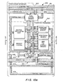
- FIGURES 10 a, b, and c illustrate in greater detail the schematic of the control panel 12 of the present invention.
- the bus lines interconnecting the components of FIGURE 9 generally form the bus line extending across the dotted lines in FIGURES 10a, b and c.
- the manual controls 350 include the variable manual controls 500, such as rotary or linear potentiometers. These controls are fed into an analog to digital converter 502.
- the manual control switches 504 are sequentially scanned by a switch scanner 506.
- the input data is transfered to input data latches 508.
- a control logic 510 having a timing generator 512 connected thereto and a control bus 514 control the operations of the converter 502, scanner 506 and data latches 508 through the latch select logic 516 and latch select bus 518.
- the output numerical displays 520 and indicator lamps 522 present output data for indicating to the operator the status of the lighting system 10.
- the output data travels through output data latches 524 controlled by control logic 510 through a latch select logic 526 and latch select bus 528.
- a display decoder 530 is required to decode data for display in numeric display 520.
- An address generator 532 is employed with an address bus 534 to control the operation of the input and output indicators.
- the bus 352 illustrated in FIGURE 9 comprises the control bus 514, address bus 534 and data buses 536 and 538. These buses enter the control interface 354 which includes dual access memories 540 and 542.
- the function of dual access memory 540 is essentially to retain the status of the controls and switches on the control panel and update this status in a continuous manner.
- the operation of dual access memory 542 is essentially to retain the status of the displays and indicator lamps on the control panel, and also update in a continuous manner.
- the control processor 358 forms the heart of the lighting system and directs each sub-function representing an indivdual variable function such as panning, tilting, intensity, color and beam divergence as zoom.
- the control processor 358 includes a central processing unit 544, an operating program memory 546 and a scratch pad memory 548.
- Control bus 550 and address bus 552 interconnect the control interface, control processor and individual function processors, and act to form the bus lines 356, 360, 364, 370, 374 and 378 of FIGURE 9.
- the operating program memory 546 contains instructions necessary for the central processing unit 544 to control the lighting system.
- the central processing unit 544 directs input information to the individual function processors or directs the individual processors to recall from memory the setting of the variable function.
- the central processing unit 544 also directs information back through the dual access memory 542 for visual display to the operator of the status of the system.
- the dual access memory 554 acts as the processor interface 362 between the control processor 358 and pan function processor 384.
- the operating program memory 556 within pan function processor 384 directs the central processing unit 558 to control the panning function.
- a scratch pad memory 560 is provided which forms a random access memory.
- the cue storage memory 386 stores the entire block of data representing the panning function for each light for every cue during a show. The relative complexity of cue storage memory 386 requires a memory control 564 for proper operation with the other components in the pan function processor.
- the control bus 566, address bus 568 and data bus 570 interconnect the various components of the pan function processor as indicated as well as the dual access memory 554 and the dual access memory 572 forming the output interface 422 as shown in FIGURE 9.
- the intensity and color function processors 400 and 408 differ by having twin dual access memories comprising the processor interface between control processor 358 and the function processor. This is necessary as the cross fade controls and preset colors require feedback to the control processor for proper operation.
- the dual access memory 572 forming the output interface of the pan function processor is connected to the address bus 574, the output data bus 576 and a control bus 578. These buses enter the data link transmitter 164 and extend to the output interfaces of the other function processors for tilt, intensity, color and zoom.
- the parallel to serial converter 580 within the data link transmitter translates the parallel format data from the individual function processors to a ordered serial data form for transmission over the data link or signal cable 18 connected to the transmitter through a line driver 582.
- the signal transmitted along data link 18 is a bipolar signal. That is, positive, negative and zero voltage level signals are employed.
- a negative voltage signal is provided as a synchronization pulse between the transmitter and receivers.
- the negative voltage signal precedes each block of serial data representing the address of a selected light and the data representing the setting of the variable functions.
- the receivers sense the negative voltage signal to synchronize the processing of the serial data by each receiver to the transmitter.
- each operating program memory such as 546 and 556 within the control panel 12 comprises a 64 kilobit memory Model 2716 sold by Mostek Corporation of Carrollton, Texas and its associated hardware.
- Each scratch pad memory such as 548 and 560 is preferably formed of a four kilobyte random access memory sold as Model 4118 by Mostek Corporation of Carrollton, Texas.
- the cue storage memory for each of the function processors is preferably an 8 kilobyte electrically alterable read only memory such as sold by General Instruments of Hicksville, N.Y. as Model ER 3400.
- the central processing units such as 544 and 558 within control panel 12 are preferably Model 1802 sold by the Radio Corporation of America of Somerville, New Jersey.
- the dual access memories such as 554 and 572 within the control panel 12 are preferably formed of a series of multiport registers Model No. 74LS170 such as sold by Texas Instruments of Dallas, Texas. While the lighting system 10 forming the present invention may be constructed with the components noted above, it would be obvious to one skilled in the art to replace or substitute the components with other components to perform substantially the same function.
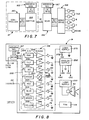
- FIGURE 8 The schematic of the receiver 166 and servo drive 168 and associated mechanisms within the light source 14 are illustrated in FIGURE 8.
- Information representing the desired settings for a selected light source is transmitted as serial data along the signal cable 18.
- the address select 167 is preprogrammed to select the address of the light source to which it is associated. If the information transmitted along the signal cable 18 does not contain the proper address, the information is rejected by the address select. If the information does contain an address corresponding to the address preprogrammed, the remainder of the serial data, containing the information for setting the light source is transmitted along a line 252 to a series of digital-to-analog converters 254 through 268.
- the numbers beside each convertor represents the number of bits necessary to communicate the setting of the variable function.
- the digital-to-analog converters translate portions of the serial data transmitted along the data line 18 to analog voltage signals.
- the digital-to-analog converter 254 controls the panning mechanism of the associated light source 14 and requires 8 bits of information for operation. The number of bits noted for each variable function in FIGURE 8 may be varied to achieve the desired resolution. For example, 8 bits of data may be used to position each dichroic filter which increases the precision in positioning the filter.
- a logic supply 270 connected to the 110 volt AC power input line 20 provides a power output 272 to operate the digital-to-analog converters.
- each converter is transmitted to an amplifier 274 through 286 for amplification and further transmitted to the associated servo motor.
- a current amplifier 290 is interconnected with the digital-to-analog converter 260 to operate the solenoid 92.
- Each of the servo motors is provided with reference voltages from an analog supply 292 so that the voltage signal input from the associated amplifier causes the servo motors to move to a predetermined position.
- the predetermined position is determined by the relative reference voltage levels provided by analog supply 292 and the voltage input from the amplifier.
- This circuit therefore provides a method for positioning the light source and determining the color, intensity and beam divergence of the light beam from the light source by use of servo motors providing accurate positioning.
- the lamp 50 is provided power through the 110 volt input line 20 and lamp supply 293.
- a fan 106 may also be provided and interconnected with the power input for cooling the light source during operation.
- the lighting system 10 has automatically variable positioning, color, intensity and beam divergence and utilizes movable dichroic filters for color variance and digital computers with storage for control of all the variable functions. While the embodiment disclosed permits 32 light sources to be independently controlled, any number of light sources may be operated by expanding the system.
- the capacity of lighting system 10 to set the variable functions of a light source from a remote position permits an individual light source to be used in different settings for different cues. Therefore, the typical requirement for 400 separate light sources all prepositioned to light an entire performance may be reduced to as few as 100 light sources 14 controlled be the lighting system 10 to thereby reduce cost.
- the lighting system 10 also eliminates the need for any dimmers, and associated cables.
- An operator at the control panel 12 of lighting system 10 may request a particular cue to be recalled from memory and each function of the light source for that cue to be set.
- the operator may adjust the variable functions for each of the light sources from control panel 12.
- the present invention therefore eliminates the slow process of positioning lights manually, setting colored gels and other steps in preparing a performance.
- the variable functions for every light source may be reset at any time, even during a performance.
- the lighting system 10 also permits the operator to vary the functions of individual light source selected even during a performance from the control panel.
Abstract
Description
- This invention relates to the illumination, in particular to the lighting of a stage or theatre.
- In conventional lighting systems, individual light sources are typically hung from trusses or fixed structural members mounted in front of the stage, at the sides of the stage or over the stage. The light sources are adjusted to direct the light beam to a desired location on the stage and are then secured in that position by tightening bolts or other fasteners. A large sealed beam lamp of 1,000 to 1,500 watts run from a 110 volt AC line is typically employed to create the light. In addition to generating visible light, such lamps, generally noted as par lamps, generate a significant amount of infrared heat.
- In a typical stage lighting plan, the light sources are employed in either of two fashions. Certain light sources may be used as a wash or general stage illumination. The remainder of the light sources are used as spots for highlighting specific positions on the stage, such as an actor's face.
- The light beams emanating from each light source may be colored by the use of a colored celluloid gel. The gel is positioned within a frame which is slid into a receiver positioned at the end of the light source so that the beam passes through the colored gel. The gel functions to absorb the incident light other than the color desired. The absorbed light is transformed into heat which warps and discolors the gel, requiring frequent replacement as often as once every show.
- Shutters are typically pivoted at the end of the light source to block out selected portions of the light beam to shape the incidence of the beam on the stage. In many cases, a mechanical iris may be provided in the light source to control the beam divergence. When a light source is used as a wash, a wide beam divergence is desired. However, when used as a spot, the light beam preferably is narrowed to a very small divergence.
- The intensity of the light beam emanating from each light source is individually controlled by a large power dimmer. The power dimmers, in turn, are controlled by the main lighting control panel. The typical lighting system therefore requires a massive array of electrical cables, including cables connecting the control console with a power dimmer and cables interconnecting the power dimmer with the associated light source. It has also been found that the use of power dimmers to control the intensity of light has induced chop in the AC power line supplying the entire theater. This has been found to induce undesirable noise, such as distortion, hum etc. particularly during the performance of rock groups employing instruments relying on electrical input.
- A typical performance, such as a rock concert or theatrical performance, may require a hundred or more individual lighting cues or lighting formats during the performance. Up to 500 separate lights may be necessary to light the entire performance. Usually 25% of these lights are used as wash and the remainder are used as specials. The large number of lights are necessitated as the light position, color, intensity and divergence must be preset prior to the performance.
- Attempts have been made to automatically control a stage lighting system during a performance. U.S. Patent No. 3,898,643 to Ettlinger, issued August 5, 1975, discloses a system including a memory for storing the intensity level of the lights for each cue during a performance. The system may then set the intensity of the light through conventional power dimmers in an automatic sequence. However, this device merely transfers the manual operation of power dimmers to an automatic system which, while relieving an operator of substantial work during the performance, necessitates still more complex and costly equipment in the system.
- In accordance with the present invention, a lighting system is provided which includes at least one light source for producing a directable beam of light mounted for pivotal motion. Pivoting mechanisms are provided for pivoting the light source to a preselected position. A controller is provided for input of a coded address representing a selected one of the light sources and data representing the preselected position of the light source. A Transmitter is provided for transmitting the coded address and data to a receiver. The receiver is provided for reading the coded address, identifying the light source corresponding to the coded address and reading the positioning data and activating the pivoting mechanism of the selected one of the light sources to pivot the light source to the preselected position.
- In accordance with another aspect of the present invention, a light source for producing a directable beam of light is provided. The light source includes a frame and a lamp for producing light positioned within the frame. At least one dichroic filter is pivotally mounted within the frame for pivotal motion into the light path for transmitting light of a preselected color, the angle of incidence of the light on the dichroic filter being variable to alter the color transmitted as the dichroic filter is pivoted.
- In accordance with yet another aspect of the present invention, a light source for producing a directable beam of light is provided which includes a frame and a lamp for producing a light position within the frame. A color wheel is rotatably mounted on the frame and has at least one dichroic filter mounted in the periphery thereof, the wheel being rotatable to position the dichroic filter across the light path transmitting a preselected color.
- In accordance with yet another aspect of the present invention, a lighting system for use in lighting an area is provided. The lighting system includes at least one light source for producing a directable beam of light, each of the light sources having a mechanism to position the light source, and a mechanism to vary the color of the beam of light produced. A controller is provided for inputing information representing the desired position and color of a selected one of the light sources. A transmitter is provided for transmitting the input information and a receiver is provided associated with the selected one of the light sources for activating the mechanisms controlling the position and color of the selected one of the light sources to correspond to the information transmitted. Mechanisms to vary the intensity and divergence of the light beam produced may also be provided and the input information contains data representing the desired setting of these functions.
- A more complete understanding of the invention may be had by reference to the following Detailed Description when taken in conjunction with the accompanying Drawings wherein:
- FIGURE 1 is a perspective view of a lighting system forming the present invention;
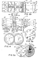
- FIGURE 2a is a vertical cross-sectional view of a first embodiment of a light source forming the present invention;
- FIGURE 2b is a horizontal cross-sectional view of the first embodiment of the light source;
- FIGURE 3 is a vertical cross-sectional view of a second embodiment of a light source forming the present invention;
- FIGURE 4 is a vertical cross section of the second embodiment of the light source taken along line 4-4 in FIGURE 3 in the direction of the arrows;
- FIGURE 5 is a vertical cross section of the second embodiment of the light source taken along line 5-5 in FIGURE 3 in the direction of the arrows;
- FIGURE 6 is an illustration of a control panel for use with the present invention;
- FIGURE 7 is a flow diagram illustrating the major functions in the lighting system of the present invention;
- FIGURE 8 is a schematic of the servo drive components associated with each light source;
- FIGURE 9 is a general schematic of the control panel of the lighting system;
- FIGURES lOa-f are a detailed schematic of the control panel of the lighting system; and
- FIGURE 11 illustrates the interrelation of FIGURES lOa-f.
- Referring now to the Drawings, wherein like reference characters designate like or corresponding parts throughout several views, FIGURE 1 illustrates a
lighting system 10 forming the present invention. Thelighting system 10 may be used to light a stage or other forum where directable light is desired. For example, thelighting system 10 may be used to light a rock concert or a theatrical performance. - As will be explained in greater detail hereinafter, the
lighting system 10 includes aremote control panel 12 for controlling thelight sources 14 mounted on atruss 16 above, in front or to the side of the stage to be lit. Eachlight source 14 may be positioned and the light beam produced thereby varied in color, intensity and beam divergence from theremote control panel 12. If the performance being lit includes a number of scenes, or individual lighting changes generally termed as cues, theremote control panel 12 includes a memory for recalling the position, color, intensity and beam divergence of eachlight source 14 for each separate cue and theremote control panel 12 will automatically set up an entire cue by the activation of a single control on thecontrol panel 12. Each function described above is accomplished with only a single two conductor data link orsignal cable 18 interconnecting thecontrol panel 12 andtruss 16 and apower cable 20. - The first embodiment of
light source 14 is illustrated in FIGURES 2a and 2b aslight 30. The light 30 includes arigid frame 32 having anaperture 34 formed in one end thereof for passage of thelight beam 36. Theframe 32 and components therein are pivotally mounted to thetruss 16 by agimbal mechanism 38. - The
gimbal mechanism 38 pivotally supports theframe 32 for motion in two mutually perpendicular planes. Theframe 32 may move in a horizontal plane or pan across a stage and in a vertical plane or tilt. Thegimbal mechanism 38 also includes motor for independently panning and tilting theframe 32 in discrete increments in response to signals generated by theremote control panel 12. The motors permit thelight beam 36 to be aimed at any desired location on the stage. In the preferred embodiment servo motors are used ingimbal mechanism 38. - A
lamp 50 is positioned withinframe 32 adjacent one end thereof. Thelamp 50 produces white light, or light across substantially the entire visible spectrum. In the preferred embodiment, thelamp 50 may comprise a common projection lamp as used in movie projectors and the like having a 110 volt AC input with a power consumption of approximately 350 watts. This type of lamp has the advantage of very low infrared radiation generation, thereby avoiding the generation of excess heat within the light 30. Anelliptic mirror 52 is positioned about thelamp 50 to reflect light incident thereon to converge at afocus 54 within theframe 32. After convergence atfocus 54, the light diverges and enters acollimating lens 56 which collimates light incident thereon to form thelight beam 36. -
Dichroic filters frame 32 on either side offocus 54. Two additionaldichroic filters lens 56opposite focus 54. Dichroic filters are available commercially, such as those sold by the Technical Products Division of Optical Coating Laboratory, Inc. of P.O. Box 1599, Santa Rosa, California. A dichroic filter is a multiple layered optical film having a glass, pyrex or quartz base. The alternate layers have low and high indexes of refraction, respectively. Dichroic filters work on an interference principle, separating two colors out of a white light source, one color being transmitted and the other color, the complement of that transmitted, being reflected. The transmitted color depends upon the type of material used in the layers and its refractive index, the thickness of each layer, the number of layers and the angle of incidence of the white light source striking the surface of the filter. By varying the angle of incidence of white light on a given filter, a preselected range of color spectrum may be produced. - The dichroic filters 58-64 are preferably formed of multiple thin layers of material and may have a circular, rectangular or other shape. The filters therefore have a thickness of a relatively small dimension and a relatively large surface for incidence of light.
Dichroic filter 58 is mounted for pivotal motion about an axis X-X byshaft 66. As can be seen with reference to - 2b, the axis X-X extends through the center of the light path.Dichroic filters shafts servo motor - When the dichroic filters are aligned with the light path, as shown in FIGURE 2b, no influence on the color is created and the filters do not significantly interfere with the light path. Therefore, a white light beam is created for use as a spot or other desired use. As a given dichroic filter is pivoted so that the angle of incidence of the light, e, increases above 0, the filter moves across the light path and transmits a colored beam with the color dependent on the angle e. The four filters may be chosen to transmit four dominant colors.
Filter 58 may transmit blue, filter 60 green, filter 62 red and filter 64 yellow. However, each individual filter will transmit a range of spectrum as e is varied. At low values of e, white light spills around the edges of the filters, diluting the transmitted beam to produce pastel or un-saturated shades of color as the beam is passed through an integratinglens 100 described hereinafter to homogenize the light beam. In the preferred embodiment, the blue and green filters are positioned furthest fromlamp 50 to formdichroic filters light beam 36 in passing light through a filter or multiple filters are theoretically infinite dependent only on the relative position of the filters. In one application of the present invention, 4,000 permutations of color are possible. - A
douser unit 90 is positioned within theframe 32. Thedouser unit 90 acts to permit thelight beam 36 to pass therethrough when open but substantially cuts off thelight beam 36 when closed. It therefore acts like a shutter to block light from passing from the light 30, but permits the light beam to be almost instantaneously restored by opening the douser unit. In the preferred embodiment, thedouser unit 90 is in the form of a mechanical shutter. The shutter is controlled by asolenoid 92 which may be activated to either close or open the shutter to control the light beam. The shutter is designed so that the shutter is closed upon deactivation of the solenoid. This feature prevents a light beam from emenating from a light when the light is malfunctioning, or the data transmitted to the light is in error to prevent improper lighting. - In close proximity with
douser unit 90 is adimmer unit 94. Thedimmer unit 94 dims or decreases the intensity oflight beam 36 to vary the mood or impact of the light on the stage. Thedimmer unit 94 is controlled by aservo motor 96. - An integrating
lens 100 is provided to mix the light passing through the dichroic filters to insure a uniform color. The integratinglens 100 is formed of a large number of smallspherical lens 102 mounted on a flat transparent surface which acts to homogenize any light passing therethrough. Finally,light beam 36 passes through a focusinglens 104 prior to exitingframe 32 throughaperture 34 to light a desired location on a stage. - The light 30 may include a cooling
fan 106 mounted in the lower base thereof. The coolingfan 106 forces outside air into the lower portion of the light to cool the electric components such asreceiver 166 andservo drive 168. A portion of the airflow is directed throughnozzles 107 at thelamp 50 to cool the lamp directly. The remainder of the air passes forward to aslot 108 adjacent the douser and dimmer units and passes to the upper portion of the light 30 to cool the lenses and dichroic filters. The air passing throughslot 108 and issuing from thenozzles 107 exits the light 30 through a grating 109 at the rear of light 30 adjacent theelliptic mirror 52. - The second embodiment of the
light source 14 is illustrated in FIGURES 3-5 and comprises light 110. Certain portions of light 110 are identical to portions of the light 30. These portions are identified by reference numerals indicating the identical portion in light 30 with a superscript '. - The frame 32' is also gimbaled on a gimbal mechanism 38'. The mechanism 38' permits the frame 32' and light beam 36' emenating therefrom to be panned and tilted across a stage.
- The lamp 50' produces white light which is reflected off the eliptical mirror 52' to converge at a focus 54' within the frame 32' of the light 110.
Color wheels 112 and l14 are rotatably mounted to frame 32' for rotation about axes R-R and S-S. The axes R-R and S-S are generally aligned with the path of light travel in the light 110 and are positioned so that the light falls on portions of the outer periphery of bothcolor wheels - Each
color wheel color wheels - At least one aperture in each wheel l12 and 114 is clear to permit passage of the light therethrough without interference. However, the remainder of the apertures have individual dichroic filters mounted therein, each filter permitting a single color to be transmitted therethrough. Each color wheel may include sufficient dichroic filters to individually provide a wide spectrum of color or, in combination with the other color wheel, provide a number of color permutations. In the preferred construction, each
color wheel 112 and l14 will have 32 apertures, one being clear and 31 having dichroic filters mounted therein. This permits almost 1000 permutations of color to be induced in the light beam 36' issuing from light 110 by rotating the twocolor wheels 112 and l14 by motor means 116 and 118, respectively. - A
gobo wheel 126 is rotatably mounted on frame 32' for rotation about axis T-T. Thegobo wheel 126 has apertures 128a-d formed in the outer periphery thereof through which substantially all the light diverging from focus 54' may pass therethrough when an aperture is centered across the light path. Again, aperture 128a does not interfere with the light travel. Theapertures 128b-d may have characters or other designs meant to project a silhouette or other background design onto the stage. A motor means such asservo motor 129 is used to rotate thegobo wheel 126 to position an aperture across the beam. - A
light intensity wheel 130 is rotatably mounted to frame 32' for rotation about an axis U-U. In the preferred embodiment, the outer periphery ofintensity wheel 130 is formed of a material permitting a percentage of light incident thereon to be transmitted therethrough which varies as a linear function of the angle Φ measured from a reference radius r. Thewheel 130 may be a transparent wheel with a reflective coating around the periphery that varies in reflectance from 0% to approximately 100%. This type of wheel is referred to as a circular variable neutral density wheel. Such a wheel is sold by Melles Griot, 1770 Kettering St., Irvine, California as a Circular Linear-Wedge N-D Filter. The periphery is sized to permit the entire light beam to be incident thereon. Portion 132a does not interfere with light passage therethrough. Portions 132b-h have progressively smaller percentages of incident light being transmitted therethrough and reflecting higher percentages of the incident light diverging from focus 54' back into the light. Thewheel 130 has been divided into 7 portions 132a-b merely for ease of discussion. The variation of Φ permits the light transmitted to be varied continuously from virtually 100% to 0% of the incident light. Preferably, thewheel 130 inportion 132h permits no light to be transmitted therethrough, forming an effective means to cut off the light beam 36'. Aservo motor 133 is used to rotate a desired portion across the light path. - In a first modification shown in FIGURE 5b,
light intensity wheel 130 may include a number of apertures formed in the outer periphery thereof. Each aperture is sized to permit the entire light beam to pass therethrough. Reflective mirrors are mounted in each of the apertures. The mirrors 132'a-h distributed about the wheel 130' have progressively smaller percentages of incident light being transmitted therethrough and reflect higher percentages of the incident light diverging from focus 54' back into the light. A servo motor may be used to rotate theintensity wheel 130 to position a mirror having a desired percentage of transmission across the light beam. Preferably, one mirror transmits substantially 100% of the light incident thereon to provide a full intensity light beam. - In a second modification, a
mechanical iris 135 would be mounted adjacent thelens 138 on either side thereof as illustrated in FIGURE 3 in phantom line. Themechanical iris 135 would be controlled by aservo motor 137 which would operate to extend or contract the iris to vary the intensity of the light beam emanating fromlight 110. - A three element zoom lens 134 is positioned within the frame 32' for controlling the divergence of the light beam 36' issuing from the light 110. The three element lens includes a
movable center lens 136 positioned between fixedouter lens center element 136 is controlled by a servo motor 142. - As is readily apparent from the description above and the referenced figures, both
lights Light 110 also permits variation of the beam divergence. These functions may be remotely controlled in a manner described hereinafter. Thelights lights - A flow chart of the
light system 10 is shown in FIGURE 7. Information representing the desired position, color, intensity and beam divergence of alight source 14 is manually entered by an operator or stored in a memory in thecontroller 160. Each individual light source is identified by a code inaddress 162. This code identifies the particular light or series of lights to which a set of variable functions is assigned. The information input tocontroller 160 is placed in a 32 bit parallel format and transferred to atransmitter 164. While a 32 bit data format is suitable for thesystem 10, it will be understood that the data format would be expendable or contractable as needed to achieve a desired control resolution. The selected light source is represented inaddress 162 by 8 bits of parallel data which is transferred intotransmitter 164.Transmitter 164 translates the parallel data into a 40 bit serial format for transmission along a two conductor twistedsignal cable 18. Thesignal cable 18 may comprise common microphone cable. The first 8 bits of the serial data transmitted represents the address of the light source. -
Signal cable 18 represents an open loop system, havingreceivers 166 branched therefrom associated with each of thelight sources 14. Eachreceiver 166 translates the first 8 bits of serial data to identify the particular light source represented by the data inaddress 167. The address select 167 includes a number of thumb operated switches for determining the address of the particular light source. If a light source mounted on the truss is rendered inoperable, the light source may be rapidly replaced with a new light source by setting the address of the new light source to correspond with the address of the failed light source. If the associated light source corresponds to the address in the data transmitted, the remaining 32 bits of data are transferred to servo drives 168 and translated from digital information to analog information for controlling the pan and tilt, color, intensity and beam divergence of the light sources. In the embodiment illustrated in FIGURE 7, four dichroic filters having the dominant colors, red, blue, green and yellow are employed represented by the letters R, B, G and Y. - The manual input by an operator of the information representing the position, color, intensity and beam divergence of the
light system 10 is best discussed with reference to thecontrol panel 12 illustrated in FIGURE 6. Thecontrol panel 12 illustrated in FIGURE 6 is designed to control 32 separate light sources such aslights 30 represented by the 32 keys in the direct assigngroup 182. The operator may address any one of the 32 light sources by depressing its associated key or a number of the light sources by sequentially depressing the key representing each of the light sources. The position of the selected light source or sources may be adjusted in unison by rotating the pan and tilt controls 184 and 186. The pan and tilt controls activate thegimble mechanism 38 associated with a light 30. Color controls 188, 190, 192 and 194 are provided for adjusting the angle e of each of the fourdichroic filters light 110, the color controls 188-194 will be replaced by two 32 position switches or other means for rotating the desired aperture of the twocolor wheels - The
intensity control 195 may be used to control the intensity of the light beam from light 30 if a mechanism is provided on the light to do so. Whencontrol panel 12 is adapted for use with the light 110, the intensity control 175 would rotate theintensity wheel 130 to adjust the intensity of the light beam as desired. - The
zoom control 196 is inactive whencontrol panel 12 is associated withlamp 30. Whencontrol panel 12 is adapted for use withlight 110, the zoom control may be used to adjust the position of the travelinglens 136. - To avoid adjusting the color of each light manually, a
color memory 198 may be provided which associates individual colors with the keys numbered 1 through 16. For example, the color controls 188, 190, 192 and 194 may be adjusted to create a blue light beam. By depressing a selected button, such as 4, incolor memory 198 and subsequently thestore key 204, the setting of the filters to provide a blue light beam will be stored within the memory. The setting may be recalled by merely depressing the key 4 incolor memory 198. This permits the operator to preprogram common colors so that one button operation will set a light to the desired color and avoid the necessity to address four controls for each color setting. - As noted previously, a concert or performance being lit typically has a number of light cues. The independent control of the variable functions in a
light source 14 within thelight system 10 permits a single light source to be used in a different position, and with a different color, intensity and beam divergence for each cue. Thecue control 200 is used to assign the information input regarding position, color, intensity and beam divergence to a particular cue. The cue selected is displayed on adisplay 202. - Having determined the position, color, intensity and beam divergence for a selected light source for a given cue, this information may be stored in a memory by depressing the store key S in
cue control 200. The information stored may be recalled at any desired moment. - Having preset the information with respect to each of the 32 light sources for every cue in a performance, it is necessary to recall the information for each light source for the cues in sequence during the performance. This is accomplished by the use of cross fade controls 206 and 208. When the
handle 210 of cross fade control 206 is moved adjacent thedisplay 214, thelight system 10 automatically recalls the information regarding each light source and activates the servo drives 168 to position the light sources, adjust the colors, intensities and beam divergences to the value set for the cue displayed indisplay 214. - As the
handle 212 on thecross fade control 208 is moved toward thedisplay 216, thelight system 10 recalls the information regarding each light source for the cue displayed indisplay 216 and activates the servo drives 168 to set the light sources for the cue displayed indisplay 216. - At the beginning of a performance, the
display 216 is typically set to zero and thedisplay 214 is set to one. With thehandles adjacent display 216, no stage lighting is provided. Both handles 210 and 212 are moved upwardadjacent display 214, thereby setting the light sources for cue I and increasing the intensity of the lights to their full value when thehandles abut display 214. Thedisplay 216 automatically resets tocue 2. At the end of the scene representing cue 1, thehandles adjacent display 216 to fade out the settings of cue 1 and fade in the settings ofcue 2. If a cue is desired out of numerical sequence, thecue control 220 may be activated to set a desired cue in eitherdisplay 214 ordisplay 216, the display elected being opposite the present position of the cross fade handles 210 and 212 so that the desired cue may be faded in by moving the handles toward the selected display. Thecue control 220 is activated to elect a cue out of sequence by depressing the E key and depressing the keys corresponding to the desired cue. A blackout -button 221 is provided for instantaneously darkening the stage by blocking the light beam from every light source. A grandmaster dimming control 222 is provided for reducing the lighting intensity from the value for a given cue to a total blackout. - A number of preset lighting cues may be desired. In particular, a general stage wash or other lighting setup may be commonly employed. Such a preselected cue may be stored in
control panel 12 and recalled by depressing a key on either upper or lower cue controls 218 and 220. If, for example, a general wash cue has been preprogrammed intoupper cue control 218 for recall by depressingkey 5, the depression ofkey 5 will cause a letter P, representing preselected and thenumber 5 to appear indisplay 214 and the preset cue will be implemented as the cross fade handles 210 and 212 are movedadjacent display 214. In a similar manner, a preselected cue may be recalled fromlower cue control 220 by depressing the associated key, which will cause the letter P and associated key number to be displayed indisplay 216 and implement the cue as the cross fade handles 210 and 212 are movedadjacent display 216. - A general schematic of the
control panel 12 of the present invention is disclosed in FIGURE 9. The manual controls 350 represent the various switches, buttons, visual displays and sliding controls such as illustrated in FIGURE 6. The manual controls 350 are interconnected by abus 352 to acontrol interface 354. Thecontrol interface 354 continuously scans the setting of themanual controls 350 and communicates through adata bus 356 to thecontrol processor 358. - The
control panel 12 operates in two separate modes. In the program mode, information is input by themanual control 350 representing the desired position, color, divergence and intensity of thelights 14 for each cue during the show. In the operate mode, thecontrol processor 358 is responsible for recalling the settings of the variable functions from various memories within the control panel and directing the remainder of the control panel to set each light 14 with the proper setting for each cue in sequential order when requested by the operator through the manual controls 350. - In the program mode, the
control processor 358 will direct information representing the desired setting for a variable function to one of the five variable function processors. For example, the panning function includes adata bus 360 interconnecting thecontrol processor 358 and aprocessor interface 362. Abus 382 interconnects the processor interface362 with thepan function processor 384. Apan cue memory 386 is interconnected with thepan function processor 384 by adata bus 388. Information input to thecontrol processor 358 regarding the panning function will be transmitted along thebus 360, throughprocessor interface 362 and intopan function processor 384 throughbus 382. Thecontrol processor 358 may direct thepan function processor 384 to store the information in thepan cue memory 386.Similar bus lines control processor 358 withprocessor interfaces bus lines tilt function processor 392,intensity function processor 400,color function processor 408 andzoon function processor 414. Thetilt cue memory 394,intensity cue memory 402,color cue memory 409 and zoomcue memory 416 are interconnected with the associated function processors bydata buses - In the operation mode, where the
control processor 358 is commanded to direct the remainder of thecontrol panel 12 to set the variable functions to values retained in each cue memory,control processor 358 acts as an interface between each of theindividual function processors control processor 358 will direct each function processor to recall from memory the setting of the variable function for a particular cue and direct this information through abus line output interface bus line data link transmitter 164. Thedata link transmitter 164 converts the parallel data output from the output interfaces to a serial data. It also acts to order the information for each address representing a light or series of lights in a preset order so that each variable function setting is represented by a known position in the stream of data. Thedata link transmitter 164 then directs the information in serial form along the data link orsignal cable 18 to thevarious receivers 166 associated with each light. - FIGURES 10 a, b, and c illustrate in greater detail the schematic of the
control panel 12 of the present invention. The components illustrated in FIGURE 9 or again illustrated in FIGURE 10 within dotted lines. The bus lines interconnecting the components of FIGURE 9 generally form the bus line extending across the dotted lines in FIGURES 10a, b and c. The manual controls 350 include the variable manual controls 500, such as rotary or linear potentiometers. These controls are fed into an analog to digital converter 502. The manual control switches 504 are sequentially scanned by aswitch scanner 506. The input data is transfered to input data latches 508. Acontrol logic 510 having atiming generator 512 connected thereto and acontrol bus 514 control the operations of the converter 502,scanner 506 and data latches 508 through the latchselect logic 516 and latchselect bus 518. - The output
numerical displays 520 andindicator lamps 522 present output data for indicating to the operator the status of thelighting system 10. The output data travels through output data latches 524 controlled bycontrol logic 510 through a latchselect logic 526 and latchselect bus 528. Adisplay decoder 530 is required to decode data for display innumeric display 520. Anaddress generator 532 is employed with anaddress bus 534 to control the operation of the input and output indicators. - The
bus 352 illustrated in FIGURE 9 comprises thecontrol bus 514,address bus 534 anddata buses control interface 354 which includesdual access memories dual access memory 540 is essentially to retain the status of the controls and switches on the control panel and update this status in a continuous manner. The operation ofdual access memory 542 is essentially to retain the status of the displays and indicator lamps on the control panel, and also update in a continuous manner. - The
control processor 358 forms the heart of the lighting system and directs each sub-function representing an indivdual variable function such as panning, tilting, intensity, color and beam divergence as zoom. Thecontrol processor 358 includes acentral processing unit 544, anoperating program memory 546 and ascratch pad memory 548.Control bus 550 andaddress bus 552 interconnect the control interface, control processor and individual function processors, and act to form thebus lines operating program memory 546 contains instructions necessary for thecentral processing unit 544 to control the lighting system. Thecentral processing unit 544 directs input information to the individual function processors or directs the individual processors to recall from memory the setting of the variable function. Thecentral processing unit 544 also directs information back through thedual access memory 542 for visual display to the operator of the status of the system. - The function of only one processor interface, function processor, cue memory and output interface will be described as the others are substantially identical. The
dual access memory 554 acts as theprocessor interface 362 between thecontrol processor 358 andpan function processor 384. Theoperating program memory 556 withinpan function processor 384 directs thecentral processing unit 558 to control the panning function. Ascratch pad memory 560 is provided which forms a random access memory. Thecue storage memory 386 stores the entire block of data representing the panning function for each light for every cue during a show. The relative complexity ofcue storage memory 386 requires amemory control 564 for proper operation with the other components in the pan function processor. Thecontrol bus 566,address bus 568 anddata bus 570 interconnect the various components of the pan function processor as indicated as well as thedual access memory 554 and thedual access memory 572 forming theoutput interface 422 as shown in FIGURE 9. The intensity andcolor function processors control processor 358 and the function processor. This is necessary as the cross fade controls and preset colors require feedback to the control processor for proper operation. - The
dual access memory 572 forming the output interface of the pan function processor is connected to theaddress bus 574, theoutput data bus 576 and acontrol bus 578. These buses enter thedata link transmitter 164 and extend to the output interfaces of the other function processors for tilt, intensity, color and zoom. The parallel toserial converter 580 within the data link transmitter translates the parallel format data from the individual function processors to a ordered serial data form for transmission over the data link orsignal cable 18 connected to the transmitter through aline driver 582. The signal transmitted alongdata link 18 is a bipolar signal. That is, positive, negative and zero voltage level signals are employed. A negative voltage signal is provided as a synchronization pulse between the transmitter and receivers. The negative voltage signal precedes each block of serial data representing the address of a selected light and the data representing the setting of the variable functions. The receivers sense the negative voltage signal to synchronize the processing of the serial data by each receiver to the transmitter. - In the preferred embodiment, each operating program memory such as 546 and 556 within the
control panel 12 comprises a 64 kilobit memory Model 2716 sold by Mostek Corporation of Carrollton, Texas and its associated hardware. Each scratch pad memory such as 548 and 560 is preferably formed of a four kilobyte random access memory sold as Model 4118 by Mostek Corporation of Carrollton, Texas. The cue storage memory for each of the function processors is preferably an 8 kilobyte electrically alterable read only memory such as sold by General Instruments of Hicksville, N.Y. as Model ER 3400. The central processing units such as 544 and 558 withincontrol panel 12 are preferably Model 1802 sold by the Radio Corporation of America of Somerville, New Jersey. The dual access memories such as 554 and 572 within thecontrol panel 12 are preferably formed of a series of multiport registers Model No. 74LS170 such as sold by Texas Instruments of Dallas, Texas. While thelighting system 10 forming the present invention may be constructed with the components noted above, it would be obvious to one skilled in the art to replace or substitute the components with other components to perform substantially the same function. - The schematic of the
receiver 166 andservo drive 168 and associated mechanisms within thelight source 14 are illustrated in FIGURE 8. Information representing the desired settings for a selected light source is transmitted as serial data along thesignal cable 18. The address select 167 is preprogrammed to select the address of the light source to which it is associated. If the information transmitted along thesignal cable 18 does not contain the proper address, the information is rejected by the address select. If the information does contain an address corresponding to the address preprogrammed, the remainder of the serial data, containing the information for setting the light source is transmitted along aline 252 to a series of digital-to-analog converters 254 through 268. The numbers beside each convertor represents the number of bits necessary to communicate the setting of the variable function. The digital-to-analog converters translate portions of the serial data transmitted along thedata line 18 to analog voltage signals. The digital-to-analog converter 254 controls the panning mechanism of the associatedlight source 14 and requires 8 bits of information for operation. The number of bits noted for each variable function in FIGURE 8 may be varied to achieve the desired resolution. For example, 8 bits of data may be used to position each dichroic filter which increases the precision in positioning the filter. Alogic supply 270 connected to the 110 volt ACpower input line 20 provides apower output 272 to operate the digital-to-analog converters. - The voltage signal produced by each converter is transmitted to an
amplifier 274 through 286 for amplification and further transmitted to the associated servo motor. In the case of thedouser unit 90, acurrent amplifier 290 is interconnected with the digital-to-analog converter 260 to operate thesolenoid 92. Each of the servo motors is provided with reference voltages from ananalog supply 292 so that the voltage signal input from the associated amplifier causes the servo motors to move to a predetermined position. The predetermined position is determined by the relative reference voltage levels provided byanalog supply 292 and the voltage input from the amplifier. This circuit therefore provides a method for positioning the light source and determining the color, intensity and beam divergence of the light beam from the light source by use of servo motors providing accurate positioning. - The
lamp 50 is provided power through the 110volt input line 20 andlamp supply 293. Afan 106 may also be provided and interconnected with the power input for cooling the light source during operation. - It can be seen from the description above and the accompanying drawings that the
lighting system 10 has automatically variable positioning, color, intensity and beam divergence and utilizes movable dichroic filters for color variance and digital computers with storage for control of all the variable functions. While the embodiment disclosedpermits 32 light sources to be independently controlled, any number of light sources may be operated by expanding the system. The capacity oflighting system 10 to set the variable functions of a light source from a remote position permits an individual light source to be used in different settings for different cues. Therefore, the typical requirement for 400 separate light sources all prepositioned to light an entire performance may be reduced to as few as 100light sources 14 controlled be thelighting system 10 to thereby reduce cost. Thelighting system 10 also eliminates the need for any dimmers, and associated cables. This vastly simplifies the procedure in setting up stage lighting and eliminates the need for long links of expensive cable. The chop found in AC power lines in conventional lighting systems is also eliminated by thepresent lighting system 10 and therefore the undesirable noise induced in electronic musical instruments and associated sound reinforcement equipment such as mixing consoles, amplifiers, etc. is reduced. - An operator at the
control panel 12 oflighting system 10 may request a particular cue to be recalled from memory and each function of the light source for that cue to be set. The operator may adjust the variable functions for each of the light sources fromcontrol panel 12. The present invention therefore eliminates the slow process of positioning lights manually, setting colored gels and other steps in preparing a performance. The variable functions for every light source may be reset at any time, even during a performance. Thelighting system 10 also permits the operator to vary the functions of individual light source selected even during a performance from the control panel. - Although several embodiments of the invention have been illustrated in the accompanying Drawings and described in the foregoing Detailed Description, it will be understood that the invention is not limited to the embodiments disclosed, but is capable of numerous rearrangements, modifications, substitution of parts and elements without departing from the spirit of the invention.
Claims (75)
and converging the reflected light to a focus located within said frame;
Priority Applications (3)
| Application Number | Priority Date | Filing Date | Title |
|---|---|---|---|
| DE8383112758T DE3279888D1 (en) | 1981-03-02 | 1982-03-02 | Light source with colour filter |
| AT82301043T ATE23624T1 (en) | 1981-03-02 | 1982-03-02 | REMOTE CONTROLLED LIGHTING SYSTEM. |
| SG66390A SG66390G (en) | 1981-03-02 | 1990-08-10 | Light source with colour filter |
Applications Claiming Priority (2)
| Application Number | Priority Date | Filing Date | Title |
|---|---|---|---|
| US06/239,367 US4392187A (en) | 1981-03-02 | 1981-03-02 | Computer controlled lighting system having automatically variable position, color, intensity and beam divergence |
| US239367 | 1981-03-02 |
Related Child Applications (1)
| Application Number | Title | Priority Date | Filing Date |
|---|---|---|---|
| EP83112758.4 Division-Into | 1983-12-19 |
Publications (2)
| Publication Number | Publication Date |
|---|---|
| EP0060068A1 true EP0060068A1 (en) | 1982-09-15 |
| EP0060068B1 EP0060068B1 (en) | 1986-11-12 |
Family
ID=22901862
Family Applications (2)
| Application Number | Title | Priority Date | Filing Date |
|---|---|---|---|
| EP83112758A Expired EP0140994B1 (en) | 1981-03-02 | 1982-03-02 | Light source with colour filter |
| EP82301043A Expired EP0060068B1 (en) | 1981-03-02 | 1982-03-02 | Remotely controlled lighting system |
Family Applications Before (1)
| Application Number | Title | Priority Date | Filing Date |
|---|---|---|---|
| EP83112758A Expired EP0140994B1 (en) | 1981-03-02 | 1982-03-02 | Light source with colour filter |
Country Status (8)
| Country | Link |
|---|---|
| US (1) | US4392187A (en) |
| EP (2) | EP0140994B1 (en) |
| JP (4) | JPS57157491A (en) |
| AT (1) | ATE45620T1 (en) |
| AU (1) | AU546433B2 (en) |
| CA (1) | CA1181795A (en) |
| DE (1) | DE3274291D1 (en) |
| HK (2) | HK28587A (en) |
Cited By (13)
| Publication number | Priority date | Publication date | Assignee | Title |
|---|---|---|---|---|
| GB2132329A (en) * | 1982-11-19 | 1984-07-04 | Michael Callahan | Followspot parameter feedback |
| FR2550867A1 (en) * | 1983-08-17 | 1985-02-22 | Collyns | Control installation, especially for light decoration. |
| EP0192882A2 (en) * | 1985-02-28 | 1986-09-03 | VARI-LITE, INC.(a Delaware corporation) | Light source having automatically variable hue, saturation and beam divergence |
| EP0248974A2 (en) * | 1986-05-15 | 1987-12-16 | VARI-LITE, INC.(a Delaware corporation) | Color wheel assembly for lighting equipment |
| EP0260895A2 (en) * | 1986-09-11 | 1988-03-23 | Starlite Technology Limited | An illumination lamp apparatus |
| GB2209229A (en) * | 1987-08-28 | 1989-05-04 | Tasco Ltd | Remote control system |
| FR2628335A1 (en) * | 1988-03-09 | 1989-09-15 | Univ Alsace | Installation for controlling sound and light show - uses local communication and power interface connected to central control computer by network bus |
| EP0332783A1 (en) * | 1988-03-09 | 1989-09-20 | Pulsar Light Of Cambridge Ltd | Improved spotlight and control system therefor |
| WO1990004242A1 (en) * | 1988-10-07 | 1990-04-19 | Swedish Airport Technology Hb | Supervision and control of airport lighting and ground movements |
| FR2667954A1 (en) * | 1990-10-12 | 1992-04-17 | Cameleon | Compact device for colouring light beams and corresponding objective |
| GB2255837A (en) * | 1991-04-16 | 1992-11-18 | Peng Seng Toh | Lighting optimization. |
| AU652409B2 (en) * | 1991-01-14 | 1994-08-25 | Vari-Lite, Inc. | Creating and controlling lighting designs |
| GB2306636A (en) * | 1995-10-20 | 1997-05-07 | Ashley & Rock Ltd | Controlled Operation of Lamps |
Families Citing this family (300)
| Publication number | Priority date | Publication date | Assignee | Title |
|---|---|---|---|---|
| US3731698A (en) * | 1971-04-05 | 1973-05-08 | G Buchalter | Cane or crutch tip |
| US4392187A (en) * | 1981-03-02 | 1983-07-05 | Vari-Lite, Ltd. | Computer controlled lighting system having automatically variable position, color, intensity and beam divergence |
| US4797795A (en) * | 1982-11-19 | 1989-01-10 | Michael Callahan | Control system for variable parameter lighting fixtures |
| US4697227A (en) * | 1982-11-19 | 1987-09-29 | Michael Callahan | Control system for variable parameter fixtures |
| US4947302A (en) * | 1982-11-19 | 1990-08-07 | Michael Callahan | Improvements to control systems for variable parameter lighting fixtures |
| US4504892A (en) * | 1983-01-21 | 1985-03-12 | Zulfilar Farida Y | Art lighting system with stepwise creation and display of workpiece |
| US4488207A (en) * | 1983-08-18 | 1984-12-11 | American Standard Inc. | Static multi-color light signal |
| US4535394A (en) * | 1983-12-08 | 1985-08-13 | Dugre Michael A | Variable color floodlight |
| JPS60140603A (en) * | 1983-12-27 | 1985-07-25 | 丸茂電機株式会社 | Dimmer for discharge lamp |
| US4631675A (en) * | 1984-07-20 | 1986-12-23 | Honeywell Inc. | Automatic light-intensity control |
| US5225765A (en) * | 1984-08-15 | 1993-07-06 | Michael Callahan | Inductorless controlled transition and other light dimmers |
| US5629607A (en) * | 1984-08-15 | 1997-05-13 | Callahan; Michael | Initializing controlled transition light dimmers |
| US5319301A (en) * | 1984-08-15 | 1994-06-07 | Michael Callahan | Inductorless controlled transition and other light dimmers |
| JPH0414803Y2 (en) * | 1985-02-14 | 1992-04-03 | ||
| US4598345A (en) * | 1985-06-06 | 1986-07-01 | Jeff Kleeman | Remote controlled illumination equipment |
| US4712167A (en) * | 1986-06-30 | 1987-12-08 | Mycro Group Co. | Remote control, moveable lighting system |
| US4709311A (en) * | 1986-07-16 | 1987-11-24 | Vari-Lite, Inc. | Lens carrier |
| CA1293989C (en) * | 1986-07-17 | 1992-01-07 | Brooks W. Taylor | Computer controlled lighting system with distributed processing |
| US5010459A (en) * | 1986-07-17 | 1991-04-23 | Vari-Lite, Inc. | Console/lamp unit coordination and communication in lighting systems |
| US4980806A (en) * | 1986-07-17 | 1990-12-25 | Vari-Lite, Inc. | Computer controlled lighting system with distributed processing |
| US4777568A (en) * | 1986-11-03 | 1988-10-11 | Altman Stage Lighting Co. | Low-inertial beam direction lighting system |
| US4753148A (en) * | 1986-12-01 | 1988-06-28 | Johnson Tom A | Sound emphasizer |
| US4837665A (en) * | 1987-12-02 | 1989-06-06 | Morpheus Lights, Inc. | Modular stage light system |
| JPH03501423A (en) * | 1987-12-02 | 1991-03-28 | モーフイアス・ライツ・インコーポレーテツド | stage lighting equipment |
| US4984143A (en) * | 1988-07-26 | 1991-01-08 | Morpheus Lights, Inc. | Color filter changer |
| JPH0236104U (en) * | 1988-08-30 | 1990-03-08 | ||
| US5078039A (en) * | 1988-09-06 | 1992-01-07 | Lightwave Research | Microprocessor controlled lamp flashing system with cooldown protection |
| US4962687A (en) * | 1988-09-06 | 1990-10-16 | Belliveau Richard S | Variable color lighting system |
| JPH0274240U (en) * | 1988-11-28 | 1990-06-06 | ||
| US4972306A (en) * | 1989-01-23 | 1990-11-20 | Vari-Lite, Inc. | Compact variable diffuser for use in a luminaire |
| US5044730A (en) * | 1989-02-08 | 1991-09-03 | Artifex Corporation | Color changing device |
| US5026152A (en) * | 1989-02-15 | 1991-06-25 | Sharkey Steven D | Enhanced cinema system |
| JPH0743961B2 (en) * | 1989-06-26 | 1995-05-15 | 丸茂電機株式会社 | Spotlight irradiation direction control device |
| US5031078A (en) * | 1989-08-28 | 1991-07-09 | Vari-Lite, Inc. | Additive color mixing system with variable hue and saturation light sources |
| US4984138A (en) * | 1989-11-16 | 1991-01-08 | Graham Gary R | Console color display |
| AU642146B2 (en) * | 1990-06-15 | 1993-10-14 | Morpheus Lights, Inc. | Scrolling primary colour changer |
| JPH0746521B2 (en) * | 1990-06-29 | 1995-05-17 | 株式会社東京放送 | Moving spot light controller |
| US5186536A (en) * | 1990-09-06 | 1993-02-16 | Vari-Lite, Inc. | Lighting instrument with movable filters and associated actuation mechanism |
| CA2051986C (en) * | 1990-10-04 | 1998-06-30 | Joseph F. Bader | Programmable emergency signalling device and system |
| JPH0498702A (en) * | 1990-10-25 | 1992-03-31 | Epotsukushiya:Kk | Spot light |
| US5207747A (en) * | 1991-04-12 | 1993-05-04 | Musco Corporation | Mobile lighting system |
| US5282121A (en) * | 1991-04-30 | 1994-01-25 | Vari-Lite, Inc. | High intensity lighting projectors |
| US6769792B1 (en) | 1991-04-30 | 2004-08-03 | Genlyte Thomas Group Llc | High intensity lighting projectors |
| US5089946A (en) * | 1991-07-10 | 1992-02-18 | Mayer Thomas A | Universal light beam manipulator |
| US5341275A (en) * | 1992-01-22 | 1994-08-23 | Abbas Ghandehari | Compact light source for fiber optics illumination |
| US5515119A (en) * | 1992-05-22 | 1996-05-07 | Panavision International, L.P. | System for varying light intensity such as for use in motion picture photography |
| US5371655A (en) * | 1992-05-22 | 1994-12-06 | Panavision International, L.P. | System for varying light intensity such as for use in motion picture photography |
| US5921659A (en) * | 1993-06-18 | 1999-07-13 | Light & Sound Design, Ltd. | Stage lighting lamp unit and stage lighting system including such unit |
| JP2918776B2 (en) * | 1993-05-19 | 1999-07-12 | ライトコミュニケーション株式会社 | Automatic writing apparatus and lighting method using the same |
| US5640061A (en) * | 1993-11-05 | 1997-06-17 | Vari-Lite, Inc. | Modular lamp power supply system |
| US5402326A (en) * | 1993-11-12 | 1995-03-28 | High End Systems, Inc. | Gobo holder for a lighting system |
| US5406176A (en) * | 1994-01-12 | 1995-04-11 | Aurora Robotics Limited | Computer controlled stage lighting system |
| DE4413943C2 (en) * | 1994-04-21 | 1997-12-04 | Feddersen Clausen Oliver | Color changing device for lighting |
| DE4447612C2 (en) * | 1994-04-21 | 1997-11-13 | Feddersen Clausen Oliver | Subtractive color mixing system |
| JP2680263B2 (en) * | 1994-05-10 | 1997-11-19 | 株式会社シアターデザイン | Remote-controlled follow spotlight controller |
| US5590954A (en) | 1994-06-15 | 1997-01-07 | Vari-Lite, Inc. | Dimmer blade |
| JPH08184567A (en) * | 1994-10-05 | 1996-07-16 | Musco Corp | Device and method for inspecting mirror reflection surface or half-mirror reflection surface |
| US5882107A (en) | 1995-11-16 | 1999-03-16 | Vari-Lite, Inc. | Compact luminaire system |
| US6421165B2 (en) | 1996-02-07 | 2002-07-16 | Light & Sound Design Ltd. | Programmable light beam shape altering device using programmable micromirrors |
| US5828485A (en) * | 1996-02-07 | 1998-10-27 | Light & Sound Design Ltd. | Programmable light beam shape altering device using programmable micromirrors |
| GB9615949D0 (en) * | 1996-07-30 | 1996-09-11 | Murtha Terence M | Light control systems |
| FR2754923B1 (en) * | 1996-10-18 | 1999-01-08 | Innova Son | CONTROL CONSOLE |
| US5791755A (en) * | 1996-11-14 | 1998-08-11 | Wybron Incorporated | Gobo handler apparatus |
| JPH10301202A (en) * | 1997-02-28 | 1998-11-13 | R D S Kk | Multiprojection system |
| US6175771B1 (en) * | 1997-03-03 | 2001-01-16 | Light & Sound Design Ltd. | Lighting communication architecture |
| US6188933B1 (en) * | 1997-05-12 | 2001-02-13 | Light & Sound Design Ltd. | Electronically controlled stage lighting system |
| US6161066A (en) * | 1997-08-18 | 2000-12-12 | The Texas A&M University System | Advanced law enforcement and response technology |
| US6188939B1 (en) | 1997-08-18 | 2001-02-13 | The Texas A&M University System | Advanced law enforcement and response technology |
| US6624597B2 (en) | 1997-08-26 | 2003-09-23 | Color Kinetics, Inc. | Systems and methods for providing illumination in machine vision systems |
| US7385359B2 (en) | 1997-08-26 | 2008-06-10 | Philips Solid-State Lighting Solutions, Inc. | Information systems |
| US6777891B2 (en) | 1997-08-26 | 2004-08-17 | Color Kinetics, Incorporated | Methods and apparatus for controlling devices in a networked lighting system |
| US6720745B2 (en) | 1997-08-26 | 2004-04-13 | Color Kinetics, Incorporated | Data delivery track |
| US6717376B2 (en) | 1997-08-26 | 2004-04-06 | Color Kinetics, Incorporated | Automotive information systems |
| US7038398B1 (en) | 1997-08-26 | 2006-05-02 | Color Kinetics, Incorporated | Kinetic illumination system and methods |
| US6897624B2 (en) | 1997-08-26 | 2005-05-24 | Color Kinetics, Incorporated | Packaged information systems |
| US20040052076A1 (en) | 1997-08-26 | 2004-03-18 | Mueller George G. | Controlled lighting methods and apparatus |
| US6548967B1 (en) * | 1997-08-26 | 2003-04-15 | Color Kinetics, Inc. | Universal lighting network methods and systems |
| US6936978B2 (en) | 1997-08-26 | 2005-08-30 | Color Kinetics Incorporated | Methods and apparatus for remotely controlled illumination of liquids |
| US7427840B2 (en) | 1997-08-26 | 2008-09-23 | Philips Solid-State Lighting Solutions, Inc. | Methods and apparatus for controlling illumination |
| US20030133292A1 (en) | 1999-11-18 | 2003-07-17 | Mueller George G. | Methods and apparatus for generating and modulating white light illumination conditions |
| US6965205B2 (en) | 1997-08-26 | 2005-11-15 | Color Kinetics Incorporated | Light emitting diode based products |
| US7231060B2 (en) * | 1997-08-26 | 2007-06-12 | Color Kinetics Incorporated | Systems and methods of generating control signals |
| US7187141B2 (en) | 1997-08-26 | 2007-03-06 | Color Kinetics Incorporated | Methods and apparatus for illumination of liquids |
| US7242152B2 (en) | 1997-08-26 | 2007-07-10 | Color Kinetics Incorporated | Systems and methods of controlling light systems |
| US7186003B2 (en) | 1997-08-26 | 2007-03-06 | Color Kinetics Incorporated | Light-emitting diode based products |
| US6781329B2 (en) | 1997-08-26 | 2004-08-24 | Color Kinetics Incorporated | Methods and apparatus for illumination of liquids |
| US6967448B2 (en) | 1997-08-26 | 2005-11-22 | Color Kinetics, Incorporated | Methods and apparatus for controlling illumination |
| US6608453B2 (en) | 1997-08-26 | 2003-08-19 | Color Kinetics Incorporated | Methods and apparatus for controlling devices in a networked lighting system |
| US6975079B2 (en) | 1997-08-26 | 2005-12-13 | Color Kinetics Incorporated | Systems and methods for controlling illumination sources |
| US6774584B2 (en) | 1997-08-26 | 2004-08-10 | Color Kinetics, Incorporated | Methods and apparatus for sensor responsive illumination of liquids |
| US6869204B2 (en) | 1997-08-26 | 2005-03-22 | Color Kinetics Incorporated | Light fixtures for illumination of liquids |
| US6888322B2 (en) * | 1997-08-26 | 2005-05-03 | Color Kinetics Incorporated | Systems and methods for color changing device and enclosure |
| US7064498B2 (en) | 1997-08-26 | 2006-06-20 | Color Kinetics Incorporated | Light-emitting diode based products |
| US7764026B2 (en) | 1997-12-17 | 2010-07-27 | Philips Solid-State Lighting Solutions, Inc. | Systems and methods for digital entertainment |
| US6806659B1 (en) | 1997-08-26 | 2004-10-19 | Color Kinetics, Incorporated | Multicolored LED lighting method and apparatus |
| US7482764B2 (en) | 1997-08-26 | 2009-01-27 | Philips Solid-State Lighting Solutions, Inc. | Light sources for illumination of liquids |
| US5969868A (en) * | 1997-09-11 | 1999-10-19 | Vari-Lite, Inc. | Sequential cross-fading color filters and system |
| DE19740592A1 (en) * | 1997-09-15 | 1999-03-18 | Soanca Pollak Georg | Lamp for different light color |
| US5975720A (en) * | 1997-09-29 | 1999-11-02 | Ricardo Lighting Company, Limited | Color changer |
| US5934794A (en) | 1997-09-30 | 1999-08-10 | Vari-Lite, Inc. | Projection gate apparatus having an axially-translatable mount |
| US6046861A (en) * | 1997-10-08 | 2000-04-04 | Vari-Lite. Inc. | Zoom lens system having imaging and non-imaging ranges |
| US6290373B1 (en) | 1997-11-21 | 2001-09-18 | Dwight Crane Rentals Ltd. | Light fixture with movable bulb carriage |
| US7132804B2 (en) * | 1997-12-17 | 2006-11-07 | Color Kinetics Incorporated | Data delivery track |
| US7598686B2 (en) | 1997-12-17 | 2009-10-06 | Philips Solid-State Lighting Solutions, Inc. | Organic light emitting diode methods and apparatus |
| US6142652A (en) * | 1998-06-15 | 2000-11-07 | Richardson; Brian Edward | Color filter module for projected light |
| US6220730B1 (en) * | 1998-07-01 | 2001-04-24 | Light & Sound Design, Ltd. | Illumination obscurement device |
| US6252358B1 (en) | 1998-08-14 | 2001-06-26 | Thomas G. Xydis | Wireless lighting control |
| JP3015010B1 (en) * | 1998-09-30 | 2000-02-28 | 日本コーバン株式会社 | Lighting equipment |
| US6175201B1 (en) * | 1999-02-26 | 2001-01-16 | Maf Technologies Corp. | Addressable light dimmer and addressing system |
| US6369524B2 (en) * | 1999-02-26 | 2002-04-09 | Maf Technologies Corp. | Addressable light dimmer and addressing system |
| US6331813B1 (en) * | 1999-05-25 | 2001-12-18 | Richard S. Belliveau | Multiparameter device control apparatus and method |
| JP2001014911A (en) * | 1999-06-28 | 2001-01-19 | Minolta Co Ltd | Lighting system |
| US6254239B1 (en) * | 1999-07-30 | 2001-07-03 | Raytheon Company | Method and system for image visualization |
| US6545586B1 (en) | 1999-11-17 | 2003-04-08 | Richard S. Belliveau | Method and apparatus for establishing and using hierarchy among remotely controllable theatre devices |
| PT1259144E (en) * | 2000-02-10 | 2009-09-17 | Light & Sound Design Ltd | Rotatable light fixture with dual hook clamp |
| EP1259838A4 (en) * | 2000-02-10 | 2009-03-25 | Light & Sound Design Ltd | Calibration for optical filter |
| US7049761B2 (en) | 2000-02-11 | 2006-05-23 | Altair Engineering, Inc. | Light tube and power supply circuit |
| US6621239B1 (en) | 2000-03-14 | 2003-09-16 | Richard S. Belliveau | Method and apparatus for controlling the temperature of a multi-parameter light |
| US7642730B2 (en) * | 2000-04-24 | 2010-01-05 | Philips Solid-State Lighting Solutions, Inc. | Methods and apparatus for conveying information via color of light |
| PT1422975E (en) | 2000-04-24 | 2010-07-09 | Philips Solid State Lighting | Light-emitting diode based product |
| US6578987B1 (en) | 2000-05-03 | 2003-06-17 | Vari-Lite, Inc. | Intra-lens color and dimming apparatus |
| US6249091B1 (en) * | 2000-05-08 | 2001-06-19 | Richard S. Belliveau | Selectable audio controlled parameters for multiparameter lights |
| US6600270B2 (en) | 2000-05-15 | 2003-07-29 | Richard S. Belliveau | Method and apparatus for generating a flash or series of flashes from a multiparameter light |
| US7202613B2 (en) | 2001-05-30 | 2007-04-10 | Color Kinetics Incorporated | Controlled lighting methods and apparatus |
| US6601973B2 (en) | 2000-06-26 | 2003-08-05 | Martin Professional A/S | Light effects system |
| US6417775B1 (en) * | 2000-07-07 | 2002-07-09 | General Electric Company | Methods and systems for monitoring lighting control and indicating failure |
| US7031920B2 (en) * | 2000-07-27 | 2006-04-18 | Color Kinetics Incorporated | Lighting control using speech recognition |
| US6346783B1 (en) | 2000-08-29 | 2002-02-12 | Richard S. Belliveau | Method and apparatus for automatically position sequencing a multiparameter light |
| US7042172B2 (en) * | 2000-09-01 | 2006-05-09 | Color Kinetics Incorporated | Systems and methods for providing illumination in machine vision systems |
| US6742916B1 (en) * | 2000-09-08 | 2004-06-01 | Charles B. Dunn | Fiber optic light assembly and mounting apparatus for boats |
| US7303300B2 (en) | 2000-09-27 | 2007-12-04 | Color Kinetics Incorporated | Methods and systems for illuminating household products |
| US6660948B2 (en) | 2001-02-28 | 2003-12-09 | Vip Investments Ltd. | Switch matrix |
| US7038399B2 (en) | 2001-03-13 | 2006-05-02 | Color Kinetics Incorporated | Methods and apparatus for providing power to lighting devices |
| US6801003B2 (en) * | 2001-03-13 | 2004-10-05 | Color Kinetics, Incorporated | Systems and methods for synchronizing lighting effects |
| US6585395B2 (en) * | 2001-03-22 | 2003-07-01 | Altman Stage Lighting Co., Inc. | Variable beam light emitting diode light source system |
| US6676275B2 (en) | 2001-04-13 | 2004-01-13 | Farsight Llc | Portable, adaptable set lighting system |
| US7598684B2 (en) | 2001-05-30 | 2009-10-06 | Philips Solid-State Lighting Solutions, Inc. | Methods and apparatus for controlling devices in a networked lighting system |
| US6635999B2 (en) | 2001-06-08 | 2003-10-21 | Richard S. Belliveau | Method and apparatus for controlling the temperature of a multiparameter light and/or a component thereof using orientation and/or parameter information |
| EP1414517A4 (en) * | 2001-06-26 | 2008-02-06 | Photomed Technologies Inc | Multiple wavelength illuminator |
| US7027736B1 (en) | 2001-11-02 | 2006-04-11 | Genlyte Thomas Group, Llc | Addressable system for light fixture modules |
| US7024119B1 (en) | 2001-11-02 | 2006-04-04 | Genlyte Thomas Group Llc | Addressable light fixture module |
| US6761470B2 (en) * | 2002-02-08 | 2004-07-13 | Lowel-Light Manufacturing, Inc. | Controller panel and system for light and serially networked lighting system |
| US6742918B2 (en) * | 2002-04-12 | 2004-06-01 | Guide Corporation | Movable condenser lens |
| US7358679B2 (en) | 2002-05-09 | 2008-04-15 | Philips Solid-State Lighting Solutions, Inc. | Dimmable LED-based MR16 lighting apparatus and methods |
| US7300192B2 (en) | 2002-10-03 | 2007-11-27 | Color Kinetics Incorporated | Methods and apparatus for illuminating environments |
| CZ301883B6 (en) * | 2002-11-15 | 2010-07-21 | Robe Lighting S.R.O. | Quick-change gobo changer system |
| US6866402B2 (en) * | 2003-02-26 | 2005-03-15 | Richard S. Belliveau | Manual and automatic locking system for a multiparameter lighting fixture |
| US7178941B2 (en) | 2003-05-05 | 2007-02-20 | Color Kinetics Incorporated | Lighting methods and systems |
| US7083304B2 (en) * | 2003-08-01 | 2006-08-01 | Illumination Management Solutions, Inc. | Apparatus and method of using light sources of differing wavelengths in an unitized beam |
| US7246917B2 (en) * | 2003-08-12 | 2007-07-24 | Illumination Management Solutions, Inc. | Apparatus and method for using emitting diodes (LED) in a side-emitting device |
| US7307542B1 (en) | 2003-09-03 | 2007-12-11 | Vantage Controls, Inc. | System and method for commissioning addressable lighting systems |
| US7755506B1 (en) | 2003-09-03 | 2010-07-13 | Legrand Home Systems, Inc. | Automation and theater control system |
| US7394451B1 (en) | 2003-09-03 | 2008-07-01 | Vantage Controls, Inc. | Backlit display with motion sensor |
| US8154841B2 (en) * | 2003-09-03 | 2012-04-10 | Legrand Home Systems, Inc. | Current zero cross switching relay module using a voltage monitor |
| US20050058702A1 (en) * | 2003-09-17 | 2005-03-17 | Ben-Sasson Shmuel A. | Compositions capable of facilitating penetration across a biological barrier |
| US6986593B2 (en) * | 2003-10-06 | 2006-01-17 | Illumination Management Solutions, Inc. | Method and apparatus for light collection, distribution and zoom |
| US20050077843A1 (en) * | 2003-10-11 | 2005-04-14 | Ronnie Benditt | Method and apparatus for controlling a performing arts show by an onstage performer |
| US7033044B2 (en) * | 2003-10-16 | 2006-04-25 | Farsight Llc | Horizontally and vertically adjustable lighting system and method |
| US7018047B2 (en) * | 2004-01-27 | 2006-03-28 | Belliveau Richard S | Image projection lighting device with variable homogeneity |
| FR2866778A1 (en) * | 2004-02-24 | 2005-08-26 | Marc Didier Patrick Pettmann | Lighting device for e.g. architectural lighting, has control case and red, green and blue LED projectors, such that connection between case and projectors ensure power supply and control light intensity and color of projectors by two wires |
| CN101619834B (en) * | 2004-03-30 | 2011-09-07 | 照明管理解决方案公司 | An apparatus and method for improved illumination area fill |
| US8960967B2 (en) | 2004-10-28 | 2015-02-24 | Ronald P. Harwood | Housing for intelligent lights |
| US20060092638A1 (en) * | 2004-10-28 | 2006-05-04 | Harwood Ronald P | Housing for intelligent lights |
| US7226188B2 (en) * | 2004-11-19 | 2007-06-05 | Whiterock Design, Llc | Stage lighting methods and apparatus |
| US7901089B2 (en) * | 2004-11-19 | 2011-03-08 | Whiterock Design, Llc | Optical system with array light source |
| US7397384B1 (en) * | 2005-02-11 | 2008-07-08 | Genlyte Thomas Group, Llc | Track lighting system current limiting device |
| US7672070B2 (en) * | 2005-10-07 | 2010-03-02 | Gebelein Family Trust | Methods and apparatus providing improved visual capabilities of optical instruments |
| DE202005012070U1 (en) * | 2005-08-01 | 2006-01-12 | Glp Light Production Gmbh | Lighting device for generating light effects and insertion for such a lighting device |
| US7488092B2 (en) * | 2005-08-05 | 2009-02-10 | Genlyte Thomas Group Llc | Track fixture with hinged accessory ring |
| US20070053188A1 (en) * | 2005-09-06 | 2007-03-08 | Luminator Holding, L.P. | LED ultraviolet air sanitizer light fixture |
| US7778262B2 (en) | 2005-09-07 | 2010-08-17 | Vantage Controls, Inc. | Radio frequency multiple protocol bridge |
| US8517666B2 (en) * | 2005-09-12 | 2013-08-27 | United Technologies Corporation | Turbine cooling air sealing |
| EP1946278A1 (en) * | 2005-09-21 | 2008-07-23 | Thales Holdings UK Plc | Method and apparatus for inducing dazzle |
| US7499206B1 (en) * | 2005-12-09 | 2009-03-03 | Brian Edward Richardson | TIR light valve |
| US8057077B2 (en) * | 2005-12-23 | 2011-11-15 | Canlyte Inc. | Support device |
| ITMI20060428A1 (en) * | 2006-03-10 | 2007-09-11 | Coemar Spa | COLOR CHANGER DEVICE PARTICULARLY FOR PROJECTORS AND THE LIKE |
| US7806961B2 (en) * | 2006-03-17 | 2010-10-05 | Em Innovative Properties Company | Control interface for a variable speed fan device |
| US20070236933A1 (en) * | 2006-04-06 | 2007-10-11 | Philips Lumileds Lighting Company Llc | Angular dependent element positioned for color tuning |
| DE202006007227U1 (en) * | 2006-04-28 | 2006-07-20 | Arnold & Richter Cine Technik Gmbh & Co. Betriebs Kg | Dimming device for a headlight |
| US7476006B2 (en) * | 2006-07-12 | 2009-01-13 | Hinds Kenneth A | Automated lighting system with extendable and retractable light units |
| US7673430B1 (en) | 2006-08-10 | 2010-03-09 | Koninklijke Philips Electronics, N.V | Recessed wall-wash staggered mounting system |
| US7600891B2 (en) | 2006-09-07 | 2009-10-13 | Belliveau Richard S | Theatre light apparatus incorporating LED tracking system |
| AU2007325132A1 (en) | 2006-11-28 | 2008-06-05 | Hayward Industries, Inc. | Programmable underwater lighting system |
| US7507005B1 (en) | 2007-01-30 | 2009-03-24 | Genlyte Thomas Group Llc | Sliding flexible track lighting |
| US7674002B1 (en) * | 2007-04-26 | 2010-03-09 | Chien Luen Industries Co., Ltd., Inc. | Solar umbrella clip light |
| US7832902B2 (en) * | 2007-06-20 | 2010-11-16 | Barco Lighting Systems, Inc. | Heat resistant color mixing flag for a multiparameter light |
| US7520763B1 (en) | 2007-06-29 | 2009-04-21 | Genlyte Thomas Group Llc | Track lighting system with dependent lamp cord |
| US10321528B2 (en) | 2007-10-26 | 2019-06-11 | Philips Lighting Holding B.V. | Targeted content delivery using outdoor lighting networks (OLNs) |
| US7950821B1 (en) | 2007-10-26 | 2011-05-31 | Georgitsis Anthony C | Auxiliary lighting systems |
| US7736023B2 (en) * | 2007-10-29 | 2010-06-15 | Barco Lightning Systems, Inc. | Selectable GOBO animation for a multiparameter light |
| US7703948B2 (en) | 2007-11-08 | 2010-04-27 | Martin Professional A/S | Interchangeable light effects |
| US8118447B2 (en) | 2007-12-20 | 2012-02-21 | Altair Engineering, Inc. | LED lighting apparatus with swivel connection |
| US7712918B2 (en) * | 2007-12-21 | 2010-05-11 | Altair Engineering , Inc. | Light distribution using a light emitting diode assembly |
| US8427274B2 (en) * | 2007-12-27 | 2013-04-23 | Saje Holdings, Inc. | Lighting system and control method thereof |
| WO2009093179A1 (en) * | 2008-01-24 | 2009-07-30 | Koninklijke Philips Electronics N.V. | Color selection input device and method |
| US8063906B2 (en) * | 2008-01-25 | 2011-11-22 | Barco Lighting Systems, Inc. | Multiparameter stage lighting apparatus with graphical output |
| US8047678B2 (en) * | 2008-01-25 | 2011-11-01 | Barco Lighting Systems, Inc. | Multiparameter stage lighting apparatus with graphical output |
| CN101514795B (en) * | 2008-02-22 | 2010-09-29 | 品生活有限公司 | Interactive light emitting diode display system for entertainment |
| US8113691B2 (en) * | 2008-03-11 | 2012-02-14 | Robe Lighting S.R.O. | Color change mechanism |
| WO2010096066A1 (en) * | 2008-03-11 | 2010-08-26 | Robe Lighting Inc | An integrated multiple output luminaire |
| US7758358B1 (en) | 2008-05-05 | 2010-07-20 | Koninklijke Philips Electronics N.V. | Track lighting assembly |
| US9063006B2 (en) * | 2008-05-09 | 2015-06-23 | The Boeing Company | Optical source assembly suitable for use as a solar simulator and associated methods |
| US8360599B2 (en) | 2008-05-23 | 2013-01-29 | Ilumisys, Inc. | Electric shock resistant L.E.D. based light |
| US20100220469A1 (en) * | 2008-05-23 | 2010-09-02 | Altair Engineering, Inc. | D-shaped cross section l.e.d. based light |
| JP2011522371A (en) * | 2008-05-29 | 2011-07-28 | コーニンクレッカ フィリップス エレクトロニクス エヌ ヴィ | Control information that controls the lighting system |
| US7976196B2 (en) * | 2008-07-09 | 2011-07-12 | Altair Engineering, Inc. | Method of forming LED-based light and resulting LED-based light |
| US7946729B2 (en) * | 2008-07-31 | 2011-05-24 | Altair Engineering, Inc. | Fluorescent tube replacement having longitudinally oriented LEDs |
| GB0815860D0 (en) * | 2008-09-01 | 2008-10-08 | Oxley Dev Co Ltd | Light emitting device |
| US8674626B2 (en) * | 2008-09-02 | 2014-03-18 | Ilumisys, Inc. | LED lamp failure alerting system |
| US8256924B2 (en) * | 2008-09-15 | 2012-09-04 | Ilumisys, Inc. | LED-based light having rapidly oscillating LEDs |
| US7887219B2 (en) * | 2008-10-23 | 2011-02-15 | Barco Lighting Systems, Inc. | Twin beam theatrical light with radial lenticular homogenizing lens |
| US8653984B2 (en) * | 2008-10-24 | 2014-02-18 | Ilumisys, Inc. | Integration of LED lighting control with emergency notification systems |
| US8324817B2 (en) | 2008-10-24 | 2012-12-04 | Ilumisys, Inc. | Light and light sensor |
| US8901823B2 (en) | 2008-10-24 | 2014-12-02 | Ilumisys, Inc. | Light and light sensor |
| US8444292B2 (en) * | 2008-10-24 | 2013-05-21 | Ilumisys, Inc. | End cap substitute for LED-based tube replacement light |
| US7938562B2 (en) | 2008-10-24 | 2011-05-10 | Altair Engineering, Inc. | Lighting including integral communication apparatus |
| US8214084B2 (en) | 2008-10-24 | 2012-07-03 | Ilumisys, Inc. | Integration of LED lighting with building controls |
| US8272770B2 (en) | 2009-01-02 | 2012-09-25 | Rambus International Ltd. | TIR switched flat panel display |
| US8152352B2 (en) * | 2009-01-02 | 2012-04-10 | Rambus International Ltd. | Optic system for light guide with controlled output |
| US8556452B2 (en) * | 2009-01-15 | 2013-10-15 | Ilumisys, Inc. | LED lens |
| US8362710B2 (en) * | 2009-01-21 | 2013-01-29 | Ilumisys, Inc. | Direct AC-to-DC converter for passive component minimization and universal operation of LED arrays |
| US8664880B2 (en) * | 2009-01-21 | 2014-03-04 | Ilumisys, Inc. | Ballast/line detection circuit for fluorescent replacement lamps |
| US8410724B2 (en) * | 2009-03-23 | 2013-04-02 | Ma Lighting Technology Gmbh | Lighting control console for controlling a lighting system |
| US8439534B1 (en) | 2009-05-06 | 2013-05-14 | George Michael Roe | Mobile lighting apparatus |
| US8330381B2 (en) | 2009-05-14 | 2012-12-11 | Ilumisys, Inc. | Electronic circuit for DC conversion of fluorescent lighting ballast |
| US8299695B2 (en) | 2009-06-02 | 2012-10-30 | Ilumisys, Inc. | Screw-in LED bulb comprising a base having outwardly projecting nodes |
| US8297818B2 (en) * | 2009-06-11 | 2012-10-30 | Rambus International Ltd. | Optical system with reflectors and light pipes |
| US8152318B2 (en) * | 2009-06-11 | 2012-04-10 | Rambus International Ltd. | Optical system for a light emitting diode with collection, conduction, phosphor directing, and output means |
| US20100315836A1 (en) * | 2009-06-11 | 2010-12-16 | Brian Edward Richardson | Flat panel optical display system with highly controlled output |
| EP2446715A4 (en) * | 2009-06-23 | 2013-09-11 | Ilumisys Inc | Illumination device including leds and a switching power control system |
| CA2765199A1 (en) * | 2009-06-23 | 2011-01-13 | Altair Engineering, Inc. | Led lamp with a wavelength converting layer |
| US20110007511A1 (en) * | 2009-07-09 | 2011-01-13 | Production Resource Group Llc | Optically Transmissive Patterned Devices Formed of Fused Silica |
| WO2011027254A1 (en) * | 2009-09-07 | 2011-03-10 | Koninklijke Philips Electronics N.V. | Picture projector |
| EP2501990A4 (en) * | 2009-11-18 | 2014-03-26 | Rambus Int Ltd | Internal collecting reflector optics for leds |
| US8317355B1 (en) | 2009-11-24 | 2012-11-27 | Chien Luen Industries Co., Ltd., Inc. | Solar umbrella clip light |
| US8430518B2 (en) | 2010-01-11 | 2013-04-30 | Cooper Technologies Company | Lighting control desk with encoders surrounded by color-coded visual indicators |
| EP2553316B8 (en) * | 2010-03-26 | 2015-07-08 | iLumisys, Inc. | Led light tube with dual sided light distribution |
| WO2011119958A1 (en) | 2010-03-26 | 2011-09-29 | Altair Engineering, Inc. | Inside-out led bulb |
| EP2553320A4 (en) | 2010-03-26 | 2014-06-18 | Ilumisys Inc | Led light with thermoelectric generator |
| US20110267834A1 (en) | 2010-04-28 | 2011-11-03 | Hayward Industries, Inc. | Underwater Light Having A Sealed Polymer Housing and Method of Manufacture Therefor |
| CN103097810B (en) * | 2010-07-08 | 2015-09-16 | 兆光科技有限公司 | For the variable space shutter of light-emitting diode display |
| US8454193B2 (en) | 2010-07-08 | 2013-06-04 | Ilumisys, Inc. | Independent modules for LED fluorescent light tube replacement |
| EP2593714A2 (en) | 2010-07-12 | 2013-05-22 | iLumisys, Inc. | Circuit board mount for led light tube |
| US8854594B2 (en) | 2010-08-31 | 2014-10-07 | Cast Group Of Companies Inc. | System and method for tracking |
| US9055226B2 (en) | 2010-08-31 | 2015-06-09 | Cast Group Of Companies Inc. | System and method for controlling fixtures based on tracking data |
| US9350923B2 (en) | 2010-08-31 | 2016-05-24 | Cast Group Of Companies Inc. | System and method for tracking |
| US20130155702A1 (en) | 2010-09-03 | 2013-06-20 | Stray Light Optical Technologies | Lighting apparatus |
| EP2625962B1 (en) | 2010-10-05 | 2017-06-21 | Kao Corporation | Concentrated coffee composition |
| US8523394B2 (en) | 2010-10-29 | 2013-09-03 | Ilumisys, Inc. | Mechanisms for reducing risk of shock during installation of light tube |
| US8870415B2 (en) | 2010-12-09 | 2014-10-28 | Ilumisys, Inc. | LED fluorescent tube replacement light with reduced shock hazard |
| US8641241B2 (en) * | 2010-12-14 | 2014-02-04 | Bridgelux, Inc. | Gimbaled LED array module |
| US8896989B2 (en) | 2011-01-12 | 2014-11-25 | Tait Towers Manufacturing, LLC | System for providing power and control signals to devices |
| TW201300702A (en) | 2011-05-13 | 2013-01-01 | Rambus Inc | Lighting assembly |
| US9072171B2 (en) | 2011-08-24 | 2015-06-30 | Ilumisys, Inc. | Circuit board mount for LED light |
| US8905380B2 (en) | 2011-11-08 | 2014-12-09 | Tait Towers Manufacturing, LLC | Chain drive control system |
| WO2013111032A1 (en) * | 2012-01-24 | 2013-08-01 | Koninklijke Philips N.V. | Lighting system and a luminaire |
| US9184518B2 (en) | 2012-03-02 | 2015-11-10 | Ilumisys, Inc. | Electrical connector header for an LED-based light |
| US8909379B2 (en) | 2012-03-07 | 2014-12-09 | Tait Towers Manufacturing, LLC | Winch control system |
| US8768492B2 (en) | 2012-05-21 | 2014-07-01 | Tait Towers Manufacturing Llc | Automation and motion control system |
| WO2014008463A1 (en) | 2012-07-06 | 2014-01-09 | Ilumisys, Inc. | Power supply assembly for led-based light tube |
| US9271367B2 (en) | 2012-07-09 | 2016-02-23 | Ilumisys, Inc. | System and method for controlling operation of an LED-based light |
| US9285084B2 (en) | 2013-03-14 | 2016-03-15 | Ilumisys, Inc. | Diffusers for LED-based lights |
| WO2014143779A2 (en) | 2013-03-15 | 2014-09-18 | Hayward Industries, Inc | Modular pool/spa control system |
| US9591722B2 (en) * | 2013-03-18 | 2017-03-07 | Ma Lighting Technology Gmbh | Lighting system |
| US9404641B2 (en) | 2013-07-10 | 2016-08-02 | Barco Lighting Systems, Inc. | Theatre light comprising of a plurality of remotely positionable light emitting modules |
| JP2015069895A (en) * | 2013-09-30 | 2015-04-13 | パナソニックIpマネジメント株式会社 | Lighting control device and lighting control system |
| US9267650B2 (en) | 2013-10-09 | 2016-02-23 | Ilumisys, Inc. | Lens for an LED-based light |
| US9291340B2 (en) | 2013-10-23 | 2016-03-22 | Rambus Delaware Llc | Lighting assembly having n-fold rotational symmetry |
| WO2015112437A1 (en) | 2014-01-22 | 2015-07-30 | Ilumisys, Inc. | Led-based light with addressed leds |
| WO2015148753A1 (en) | 2014-03-27 | 2015-10-01 | Loto Lighting Llc | Motorized light assembly |
| KR102173903B1 (en) * | 2014-05-08 | 2020-11-06 | 삼성디스플레이 주식회사 | Laminate apparatus |
| US9510400B2 (en) | 2014-05-13 | 2016-11-29 | Ilumisys, Inc. | User input systems for an LED-based light |
| US9429926B2 (en) | 2014-05-16 | 2016-08-30 | Tait Towers Manufacturing, LLC | Automation and motion control system |
| EP3237796B1 (en) | 2014-10-01 | 2019-12-04 | Robe Lighting s.r.o. | Improved coordinated effects system for an automated luminaire |
| US10724710B2 (en) | 2014-10-01 | 2020-07-28 | Robe Lighting S.R.O. | Framing system for an automated luminaire |
| US10161568B2 (en) | 2015-06-01 | 2018-12-25 | Ilumisys, Inc. | LED-based light with canted outer walls |
| AU2016277461A1 (en) | 2015-06-09 | 2018-01-18 | Liam FEENEY | A visual tracking system and method |
| US10057964B2 (en) | 2015-07-02 | 2018-08-21 | Hayward Industries, Inc. | Lighting system for an environment and a control module for use therein |
| JP2017123317A (en) * | 2016-01-08 | 2017-07-13 | パナソニックIpマネジメント株式会社 | Luminaire |
| EP4343457A2 (en) | 2016-01-22 | 2024-03-27 | Hayward Industries, Inc. | Systems and methods for providing network connectivity and remote monitoring, optimization, and control of pool/spa equipment |
| US11720085B2 (en) | 2016-01-22 | 2023-08-08 | Hayward Industries, Inc. | Systems and methods for providing network connectivity and remote monitoring, optimization, and control of pool/spa equipment |
| CN106016166B (en) * | 2016-06-23 | 2019-04-16 | 安徽雷池机械制造有限公司 | A kind of stage lamp mounting structure |
| IT201600083994A1 (en) * | 2016-08-09 | 2018-02-09 | Clay Paky Spa | HEADLAMP, PREFERABLY FROM STAGE |
| EP3538049A1 (en) | 2016-11-08 | 2019-09-18 | Optimus Licensing AG | Integrated operating room lighting and patient warming system - design and components |
| US20180172266A1 (en) * | 2016-12-21 | 2018-06-21 | Electric Horsepower Inc. | Electric resistance heater system and light tower |
| US10393355B2 (en) * | 2017-03-02 | 2019-08-27 | International Business Machines Corporation | Lighting pattern optimization for a task performed in a vicinity |
| US10718486B2 (en) | 2017-05-06 | 2020-07-21 | Richard S. Belliveau | Theatre light projector incorporating a plurality of light sources and improvements to blending the light output |
| US10344944B2 (en) | 2017-05-06 | 2019-07-09 | Richard S. Belliveau | Theatre light projector incorporating a plurality of light sources and improvements to blending the light output |
| US10111295B1 (en) | 2017-10-17 | 2018-10-23 | Richard S. Belliveau | Methods and improvements to spectral monitoring of theatre lighting devices |
| US10156350B1 (en) | 2017-10-17 | 2018-12-18 | Richard S. Belliveau | Methods and improvements to spectral monitoring of theatre lighting devices |
| CN107842815B (en) * | 2017-10-19 | 2023-12-01 | 广州市浩洋电子股份有限公司 | Stage lamp color temperature compensation system and method |
| WO2019084193A1 (en) | 2017-10-25 | 2019-05-02 | Nicor, Inc. | Method and system for power supply control |
| US11620131B2 (en) * | 2017-10-25 | 2023-04-04 | Nicor, Inc. | Methods and systems for illumination power, management, and control |
| CN108107648A (en) * | 2018-01-31 | 2018-06-01 | 苏州振旺光电有限公司 | Filter plate switching device, imaging device and position control method |
| IT201800003698A1 (en) * | 2018-03-16 | 2019-09-16 | Linea Light S R L | LIGHTING DEVICE |
| US20200116460A1 (en) * | 2018-10-16 | 2020-04-16 | Meopta U.S.A., Inc. | Lighting system for indoor shooting ranges |
| US11168876B2 (en) | 2019-03-06 | 2021-11-09 | Hayward Industries, Inc. | Underwater light having programmable controller and replaceable light-emitting diode (LED) assembly |
| CA3088929A1 (en) * | 2019-08-02 | 2021-02-02 | Wideband Labs, LLC | Management system for closed environmental facilities |
| US10619827B1 (en) | 2019-10-15 | 2020-04-14 | Bml Productions, Inc. | Modular controllable lighting fixtures |
| US10900649B1 (en) | 2020-06-02 | 2021-01-26 | Bml Productions, Inc. | Event lighting and auxiliary components for use therewith |
Citations (3)
| Publication number | Priority date | Publication date | Assignee | Title |
|---|---|---|---|---|
| BE752896A (en) * | 1970-07-02 | 1970-12-16 | Adrien De Backer Ets | CENTRAL MEMORY LIGHTING CONTROL SYSTEM. |
| US3845351A (en) * | 1970-03-05 | 1974-10-29 | Ballmoos F Von | Method and apparatus for the adjustment of a plurality of floodlights |
| GB1434052A (en) * | 1973-03-07 | 1976-04-28 | Thorn Lighting Ltd | Control apparatus for controlling a multiplicity of different outputs successively by means of a single mechanical input device |
Family Cites Families (41)
| Publication number | Priority date | Publication date | Assignee | Title |
|---|---|---|---|---|
| US1820899A (en) * | 1924-04-10 | 1931-08-25 | Greenewalt Mary Hallock | Lighting appliance |
| US1751011A (en) * | 1928-08-09 | 1930-03-18 | Jr Horace G Martin | Electric lamp |
| US2009145A (en) * | 1933-11-20 | 1935-07-23 | Nathan George | Ray tinting device |
| US2192520A (en) * | 1936-10-07 | 1940-03-05 | Century Lighting Inc | Remote control color changer for projected light |
| US2214728A (en) * | 1936-10-31 | 1940-09-17 | Minneapolishoneywell Regulator | Color wheel centering device |
| US2447724A (en) * | 1945-09-04 | 1948-08-24 | Simmon Brothers Inc | Color control for photographic enlargers |
| US2625851A (en) * | 1949-04-29 | 1953-01-20 | Joseph Gelb Company | Camera lens board and means for controlling the same |
| US2659038A (en) * | 1949-08-15 | 1953-11-10 | Eric H Heyer | Automatic illumination system |
| US2660926A (en) * | 1950-04-13 | 1953-12-01 | Maurice I Talley | Plural filter support and actuating mechanism |
| US2687669A (en) * | 1951-06-27 | 1954-08-31 | Bolsey Jacques | Motion-picture camera lens and filter turret locking mechanism |
| US2841065A (en) * | 1952-11-07 | 1958-07-01 | Warner Bros | Color film printer |
| US2751011A (en) * | 1954-02-12 | 1956-06-19 | Madge Johnston | Side wall testing apparatus |
| US2896499A (en) * | 1956-02-24 | 1959-07-28 | Philips Corp | Colour-selective optical system corrected with regard to astigmatism |
| US2911519A (en) * | 1956-09-18 | 1959-11-03 | Rodney Perdew | Remote controlled hospital light |
| US2950382A (en) * | 1956-12-17 | 1960-08-23 | Strong Electric Corp | Projection lamp |
| US2951430A (en) * | 1957-09-26 | 1960-09-06 | Roloc Inc | Photographic printing machine |
| US3085468A (en) * | 1959-01-21 | 1963-04-16 | Lester C Hehn | Dichroic filter color balance systems |
| US3184307A (en) * | 1959-08-14 | 1965-05-18 | Eastman Kodak Co | Method and apparatus for making color prints |
| US3107578A (en) * | 1959-12-05 | 1963-10-22 | Agfa Ag | Filter-operating arrangement for a photographic printing apparatus |
| DE1137703B (en) * | 1961-03-30 | 1962-10-11 | Zeiss Ikon Ag | Adjustable lighting device, especially operating room light |
| US3045208A (en) * | 1961-04-05 | 1962-07-17 | Amalia Tiberio | Rotatable stop light |
| FR1390528A (en) * | 1964-03-03 | 1965-02-26 | Bouwstoffen V H A E Braat Nv | Translucent and more particularly transparent diffusing plate |
| US3382024A (en) * | 1964-08-06 | 1968-05-07 | Ling Temco Vought Inc | Optical filter changing mechanism |
| US3515800A (en) * | 1966-05-10 | 1970-06-02 | Victor Company Of Japan | Television camera for selectively picking up scenes in color or monochromatically |
| US3529889A (en) * | 1968-02-12 | 1970-09-22 | Perkin Elmer Corp | Optical filter changing mechanism |
| JPS5225667B1 (en) * | 1971-04-18 | 1977-07-08 | ||
| US3783263A (en) * | 1971-08-19 | 1974-01-01 | W Cruse | Remote lighting control system |
| JPS4842580A (en) * | 1971-10-07 | 1973-06-20 | ||
| JPS4852364U (en) * | 1971-10-13 | 1973-07-07 | ||
| GB1426756A (en) * | 1973-02-22 | 1976-03-03 | Rank Organisation Ltd | Variable colour light beam producing device |
| US3833295A (en) * | 1973-03-16 | 1974-09-03 | Eastman Kodak Co | Energy absorbing mounting for optical modulation assemblies |
| JPS5315923Y2 (en) * | 1973-08-02 | 1978-04-26 | ||
| US3883243A (en) * | 1973-09-25 | 1975-05-13 | Berkey Photo Inc | Light color regulating apparatus |
| DE2354070C2 (en) * | 1973-10-29 | 1975-09-11 | Feinmechanische Werke Mainz Gmbh, 6500 Mainz | Device for remote-controllable and programmable positioning of height-adjustable, rotatable and pivotable devices provided with air cooling, in particular studio spotlights |
| JPS5116126U (en) * | 1974-07-25 | 1976-02-05 | ||
| US4037097A (en) * | 1975-04-04 | 1977-07-19 | Stillman Allen M | Color changer for spotlights |
| JPS5219712A (en) * | 1975-08-08 | 1977-02-15 | Nakayama Steel Works Ltd | Production of hard water crushed slag |
| DE2541503C3 (en) * | 1975-09-17 | 1980-06-26 | Heine Optotechnik Gmbh & Co Kg, 8036 Herrsching | Filter arrangement for optical examination devices |
| US4112486A (en) * | 1976-05-26 | 1978-09-05 | Murray Tovi Designs, Inc. | Remotely controlled positioning device for illuminating unit and the like |
| US4167783A (en) * | 1977-08-30 | 1979-09-11 | Mitchell William P | Portable lighting system having a foot operated dimmer |
| US4392187A (en) * | 1981-03-02 | 1983-07-05 | Vari-Lite, Ltd. | Computer controlled lighting system having automatically variable position, color, intensity and beam divergence |
-
1981
- 1981-03-02 US US06/239,367 patent/US4392187A/en not_active Expired - Lifetime
-
1982
- 1982-01-19 CA CA000394462A patent/CA1181795A/en not_active Expired
- 1982-01-20 AU AU79646/82A patent/AU546433B2/en not_active Expired
- 1982-03-02 EP EP83112758A patent/EP0140994B1/en not_active Expired
- 1982-03-02 JP JP57031864A patent/JPS57157491A/en active Granted
- 1982-03-02 DE DE8282301043T patent/DE3274291D1/en not_active Expired
- 1982-03-02 EP EP82301043A patent/EP0060068B1/en not_active Expired
- 1982-03-02 AT AT83112758T patent/ATE45620T1/en not_active IP Right Cessation
-
1984
- 1984-10-26 JP JP59224237A patent/JPS60143502A/en active Granted
-
1985
- 1985-10-16 JP JP60228973A patent/JPS61173402A/en active Pending
-
1987
- 1987-04-09 HK HK285/87A patent/HK28587A/en not_active IP Right Cessation
-
1989
- 1989-03-06 JP JP1053586A patent/JPH0215505A/en active Granted
-
1990
- 1990-11-15 HK HK956/90A patent/HK95690A/en not_active IP Right Cessation
Patent Citations (5)
| Publication number | Priority date | Publication date | Assignee | Title |
|---|---|---|---|---|
| US3845351A (en) * | 1970-03-05 | 1974-10-29 | Ballmoos F Von | Method and apparatus for the adjustment of a plurality of floodlights |
| US3845351B1 (en) * | 1970-03-05 | 1987-10-13 | ||
| US3845351B2 (en) * | 1970-03-05 | 1990-10-02 | Method and apparatus for the adjustment of a plurality of floodlights | |
| BE752896A (en) * | 1970-07-02 | 1970-12-16 | Adrien De Backer Ets | CENTRAL MEMORY LIGHTING CONTROL SYSTEM. |
| GB1434052A (en) * | 1973-03-07 | 1976-04-28 | Thorn Lighting Ltd | Control apparatus for controlling a multiplicity of different outputs successively by means of a single mechanical input device |
Cited By (20)
| Publication number | Priority date | Publication date | Assignee | Title |
|---|---|---|---|---|
| GB2168138A (en) * | 1982-11-19 | 1986-06-11 | Michael Callahan | Performance lighting system |
| GB2132329A (en) * | 1982-11-19 | 1984-07-04 | Michael Callahan | Followspot parameter feedback |
| FR2550867A1 (en) * | 1983-08-17 | 1985-02-22 | Collyns | Control installation, especially for light decoration. |
| EP0192882A2 (en) * | 1985-02-28 | 1986-09-03 | VARI-LITE, INC.(a Delaware corporation) | Light source having automatically variable hue, saturation and beam divergence |
| EP0192882A3 (en) * | 1985-02-28 | 1988-08-03 | Vari-Lite, Inc. | Light source having automatically variable hue, saturation and beam divergence |
| EP0248974A2 (en) * | 1986-05-15 | 1987-12-16 | VARI-LITE, INC.(a Delaware corporation) | Color wheel assembly for lighting equipment |
| EP0248974A3 (en) * | 1986-05-15 | 1989-07-26 | Vari-Lite, Inc. | Color wheel assembly for lighting equipment |
| EP0260895A2 (en) * | 1986-09-11 | 1988-03-23 | Starlite Technology Limited | An illumination lamp apparatus |
| EP0260895A3 (en) * | 1986-09-11 | 1989-07-26 | Starlite Technology Limited | An illumination lamp apparatus |
| GB2209229B (en) * | 1987-08-28 | 1991-12-04 | Tasco Ltd | Remote control system |
| GB2209229A (en) * | 1987-08-28 | 1989-05-04 | Tasco Ltd | Remote control system |
| FR2628335A1 (en) * | 1988-03-09 | 1989-09-15 | Univ Alsace | Installation for controlling sound and light show - uses local communication and power interface connected to central control computer by network bus |
| EP0332783A1 (en) * | 1988-03-09 | 1989-09-20 | Pulsar Light Of Cambridge Ltd | Improved spotlight and control system therefor |
| WO1990004242A1 (en) * | 1988-10-07 | 1990-04-19 | Swedish Airport Technology Hb | Supervision and control of airport lighting and ground movements |
| US5426429A (en) * | 1988-10-07 | 1995-06-20 | Airport Technology In Scandinavia Ab | Supervision and control of airport lighting and ground movements |
| US6573840B1 (en) | 1988-10-07 | 2003-06-03 | Airport Technology In Scandinavia | Supervision and control of airport lighting and ground movements |
| FR2667954A1 (en) * | 1990-10-12 | 1992-04-17 | Cameleon | Compact device for colouring light beams and corresponding objective |
| AU652409B2 (en) * | 1991-01-14 | 1994-08-25 | Vari-Lite, Inc. | Creating and controlling lighting designs |
| GB2255837A (en) * | 1991-04-16 | 1992-11-18 | Peng Seng Toh | Lighting optimization. |
| GB2306636A (en) * | 1995-10-20 | 1997-05-07 | Ashley & Rock Ltd | Controlled Operation of Lamps |
Also Published As
| Publication number | Publication date |
|---|---|
| EP0140994A3 (en) | 1985-09-11 |
| JPS60143502A (en) | 1985-07-29 |
| JPH0350361B2 (en) | 1991-08-01 |
| HK95690A (en) | 1990-11-23 |
| EP0060068B1 (en) | 1986-11-12 |
| JPH0215505A (en) | 1990-01-19 |
| HK28587A (en) | 1987-04-16 |
| JPS57157491A (en) | 1982-09-29 |
| DE3274291D1 (en) | 1987-01-02 |
| CA1181795A (en) | 1985-01-29 |
| JPH0412561B2 (en) | 1992-03-05 |
| US4392187A (en) | 1983-07-05 |
| EP0140994B1 (en) | 1989-08-16 |
| JPS61173402A (en) | 1986-08-05 |
| AU7964682A (en) | 1982-09-09 |
| ATE45620T1 (en) | 1989-09-15 |
| AU546433B2 (en) | 1985-08-29 |
| EP0140994A2 (en) | 1985-05-15 |
| JPS6412041B2 (en) | 1989-02-28 |
Similar Documents
| Publication | Publication Date | Title |
|---|---|---|
| US4392187A (en) | Computer controlled lighting system having automatically variable position, color, intensity and beam divergence | |
| US4697227A (en) | Control system for variable parameter fixtures | |
| US4797795A (en) | Control system for variable parameter lighting fixtures | |
| US5788365A (en) | Stage lighting lamp unit and stage lighting system including such unit | |
| US6894443B2 (en) | Stage lighting lamp unit and stage lighting system including such unit | |
| US4894760A (en) | Additive color-mixing light fixture employing a single moveable multi-filter array | |
| US5031078A (en) | Additive color mixing system with variable hue and saturation light sources | |
| US5045983A (en) | Computer controlled light with continuously variable color temperature, color, magnification, focus, and position | |
| EP0192882B1 (en) | Light source having automatically variable hue, saturation and beam divergence | |
| US4298920A (en) | Automatic gel changer for a spotlight | |
| US4899267A (en) | Spotlight and control system therefor | |
| GB2342466A (en) | Light projector | |
| JP2533267B2 (en) | Lighting equipment | |
| US6249092B1 (en) | Dimmable lighting apparatus using a discharge lamp | |
| EP0929776B1 (en) | Projector device for a multi-colour light beam | |
| JP3538897B2 (en) | Mobile lighting device | |
| US7527382B2 (en) | Image projection lighting device with variable homogeneity | |
| GB2341113A (en) | Apparatus for controlling light | |
| GB2215486A (en) | Improved spotlight and control system therefor | |
| CA2015883A1 (en) | Computer controlled light with continuously variable colour temperature, colour modification, focus and position |
Legal Events
| Date | Code | Title | Description |
|---|---|---|---|
| PUAI | Public reference made under article 153(3) epc to a published international application that has entered the european phase |
Free format text: ORIGINAL CODE: 0009012 |
|
| AK | Designated contracting states |
Designated state(s): AT BE CH DE FR GB IT LI SE |
|
| 17P | Request for examination filed |
Effective date: 19830216 |
|
| RAP1 | Party data changed (applicant data changed or rights of an application transferred) |
Owner name: VARI-LITE, INC. |
|
| GRAA | (expected) grant |
Free format text: ORIGINAL CODE: 0009210 |
|
| AK | Designated contracting states |
Kind code of ref document: B1 Designated state(s): AT BE CH DE FR GB IT LI SE |
|
| REF | Corresponds to: |
Ref document number: 23624 Country of ref document: AT Date of ref document: 19861115 Kind code of ref document: T |
|
| ET | Fr: translation filed | ||
| REF | Corresponds to: |
Ref document number: 3274291 Country of ref document: DE Date of ref document: 19870102 |
|
| ITF | It: translation for a ep patent filed |
Owner name: STUDIO TORTA SOCIETA' SEMPLICE |
|
| PLBE | No opposition filed within time limit |
Free format text: ORIGINAL CODE: 0009261 |
|
| STAA | Information on the status of an ep patent application or granted ep patent |
Free format text: STATUS: NO OPPOSITION FILED WITHIN TIME LIMIT |
|
| 26N | No opposition filed | ||
| REG | Reference to a national code |
Ref country code: FR Ref legal event code: TP |
|
| ITTA | It: last paid annual fee | ||
| REG | Reference to a national code |
Ref country code: GB Ref legal event code: 732E |
|
| EAL | Se: european patent in force in sweden |
Ref document number: 82301043.4 |
|
| PGFP | Annual fee paid to national office [announced via postgrant information from national office to epo] |
Ref country code: FR Payment date: 20010219 Year of fee payment: 20 |
|
| PGFP | Annual fee paid to national office [announced via postgrant information from national office to epo] |
Ref country code: DE Payment date: 20010220 Year of fee payment: 20 |
|
| PGFP | Annual fee paid to national office [announced via postgrant information from national office to epo] |
Ref country code: GB Payment date: 20010221 Year of fee payment: 20 Ref country code: CH Payment date: 20010221 Year of fee payment: 20 Ref country code: AT Payment date: 20010221 Year of fee payment: 20 |
|
| PGFP | Annual fee paid to national office [announced via postgrant information from national office to epo] |
Ref country code: SE Payment date: 20010222 Year of fee payment: 20 |
|
| PGFP | Annual fee paid to national office [announced via postgrant information from national office to epo] |
Ref country code: BE Payment date: 20010306 Year of fee payment: 20 |
|
| BE20 | Be: patent expired |
Free format text: 20020302 *VARI-LITE INC. |
|
| REG | Reference to a national code |
Ref country code: GB Ref legal event code: IF02 |
|
| PG25 | Lapsed in a contracting state [announced via postgrant information from national office to epo] |
Ref country code: LI Free format text: LAPSE BECAUSE OF EXPIRATION OF PROTECTION Effective date: 20020301 Ref country code: GB Free format text: LAPSE BECAUSE OF EXPIRATION OF PROTECTION Effective date: 20020301 Ref country code: CH Free format text: LAPSE BECAUSE OF EXPIRATION OF PROTECTION Effective date: 20020301 |
|
| PG25 | Lapsed in a contracting state [announced via postgrant information from national office to epo] |
Ref country code: AT Free format text: LAPSE BECAUSE OF EXPIRATION OF PROTECTION Effective date: 20020302 |
|
| REG | Reference to a national code |
Ref country code: GB Ref legal event code: PE20 Effective date: 20020301 |
|
| REG | Reference to a national code |
Ref country code: CH Ref legal event code: PL |
|
| EUG | Se: european patent has lapsed |
Ref document number: 82301043.4 |