EP0059952A1 - Method and apparatus for controlling a plurality of devices - Google Patents
Method and apparatus for controlling a plurality of devices Download PDFInfo
- Publication number
- EP0059952A1 EP0059952A1 EP82101739A EP82101739A EP0059952A1 EP 0059952 A1 EP0059952 A1 EP 0059952A1 EP 82101739 A EP82101739 A EP 82101739A EP 82101739 A EP82101739 A EP 82101739A EP 0059952 A1 EP0059952 A1 EP 0059952A1
- Authority
- EP
- European Patent Office
- Prior art keywords
- vocal
- manipulative
- responsive
- predetermined
- sound
- Prior art date
- Legal status (The legal status is an assumption and is not a legal conclusion. Google has not performed a legal analysis and makes no representation as to the accuracy of the status listed.)
- Granted
Links
Images


Classifications
-
- B—PERFORMING OPERATIONS; TRANSPORTING
- B60—VEHICLES IN GENERAL
- B60R—VEHICLES, VEHICLE FITTINGS, OR VEHICLE PARTS, NOT OTHERWISE PROVIDED FOR
- B60R16/00—Electric or fluid circuits specially adapted for vehicles and not otherwise provided for; Arrangement of elements of electric or fluid circuits specially adapted for vehicles and not otherwise provided for
- B60R16/02—Electric or fluid circuits specially adapted for vehicles and not otherwise provided for; Arrangement of elements of electric or fluid circuits specially adapted for vehicles and not otherwise provided for electric constitutive elements
- B60R16/037—Electric or fluid circuits specially adapted for vehicles and not otherwise provided for; Arrangement of elements of electric or fluid circuits specially adapted for vehicles and not otherwise provided for electric constitutive elements for occupant comfort, e.g. for automatic adjustment of appliances according to personal settings, e.g. seats, mirrors, steering wheel
- B60R16/0373—Voice control
-
- B—PERFORMING OPERATIONS; TRANSPORTING
- B60—VEHICLES IN GENERAL
- B60H—ARRANGEMENTS OF HEATING, COOLING, VENTILATING OR OTHER AIR-TREATING DEVICES SPECIALLY ADAPTED FOR PASSENGER OR GOODS SPACES OF VEHICLES
- B60H1/00—Heating, cooling or ventilating [HVAC] devices
- B60H1/00642—Control systems or circuits; Control members or indication devices for heating, cooling or ventilating devices
- B60H1/00735—Control systems or circuits characterised by their input, i.e. by the detection, measurement or calculation of particular conditions, e.g. signal treatment, dynamic models
- B60H1/00757—Control systems or circuits characterised by their input, i.e. by the detection, measurement or calculation of particular conditions, e.g. signal treatment, dynamic models by the input of sound, e.g. by using a voice synthesizer
-
- H—ELECTRICITY
- H03—ELECTRONIC CIRCUITRY
- H03G—CONTROL OF AMPLIFICATION
- H03G1/00—Details of arrangements for controlling amplification
- H03G1/02—Remote control of amplification, tone, or bandwidth
-
- H—ELECTRICITY
- H03—ELECTRONIC CIRCUITRY
- H03J—TUNING RESONANT CIRCUITS; SELECTING RESONANT CIRCUITS
- H03J1/00—Details of adjusting, driving, indicating, or mechanical control arrangements for resonant circuits in general
- H03J1/02—Indicating arrangements
- H03J1/025—Indicating arrangements with voiced announcement
Abstract
Description
- This invention relates generally to method and apparatus for controlling various devices and equipment mounted on a vehicle, such as an automobile, and more particularly, the present invention relates to control of vehicle mounted devices whose operating conditions can be changed as desired.
- Conventionally, changes of operating conditions of various devices and equipment in an automobile, for instance, a radio receiver, a stereo unit, an air conditioner or the like, have been effected manually by the occupant of the automobile. Namely, when the driver or the passenger of the motor vehicle ihtends to listen to a radio, he manually turns* on the switch ot the radio, and then he tunes the radio to a desired broadcasting frequency. Furthermore, he may manipulate the sound volume adjusting knob of the radio to set the sound volume to a desired level. In the same manner, when it is intended to operate a stereo unit or an air conditioning system of the motor vehicle, the occupant manipulates a corresponding switch or key to turn on a desired device, and then necessary adjustment, such as adjustment of temperature or the operating mode, is manually, effected.
- However, the manual operation of such switches, keys or the like tends to distract the vehicle driver from steering efforts to such an extent that it might lead to a dangerous situation. Therefore, there have been a problem that manipulation for changing the operating condition of the vehicle mounted devices cannot be effected readily when the motor vehicle is running. The main reason for the-difficulty of manipulation of the switches or the like of such devices resides in the fact that the positions of the manipulative switches or the like cannot be accurately recognized by the driver since his attention is mainly paid to the front of the motor vehicle.
- The present invention has been developed in order to - provide a method and apparatus for controlling various devices and equipment mounted on a vehicle so that the vehicle driver is not bothered by manipulation of various switches, knobs or the like.
- It is, therefore, an object of the present invention to provide a method and apparatus for automatically controlling various devices mounted on a vehicle with simple instructions from the occupant so that safe driving is ensured.
- According to a feature of the present invention, sequential vocal announcements are emitted from a vehicle mounted speaker so that the vehicle occupant can selectively respond to a desired announcement. The announcements include various names of the devices to be operated and names of operations or manipulations to be performed. The occupant issues responsive instructions against an announcement when he wishes the named device to operate. The responsive instruction may be given either by manipulating a single switch or button or by pronouncing predetermined vocal sounds. In the case that the responsive instructions are given by vocal sounds, a sound recognizer responds to the vocal sounds to detect the contents thereof. Various operating conditions, such as tuning of a radio, sound volume control of the radio or a stereo unit, temperature control and operating mode control of an air conditioner, may be effected by supplying the vehicle occupant with corresponding information and by receiving responsive instructions from the occupant in the same manner.
- Although the emobodiments of the present invention will be described in connection with the control of vehicle mounted devices. the invention may be adapted to control devices in a factory, plant or the like so that a number of manipulations of various devices can be simply controlled with a single switch or by talking to a vocal sound responsive unit.
- \ , In accordance with the present invention there is provided a method of controlling devices each having at least one manipulative element, comprising the steps of: detecting an action of an operator indicating that a demand has occurred for a change in operating conditions of at least one of said devices which are arranged to operate under the control ot predetermined instructions; emitting sequential vocal announcements each corresponding to the manipulations of manipulative elements of said devices in response to the detection of said action, each of said vocal announcements being emitted at an interval to allow the operator to issue responsive instructions; monitoring said responsive instructions from the operator for a predetermined period of time after the emission of each announcement; and changing the operating conditions of one of said devices by automatically operating one of said manipulative element which has been announced just before the receipt of said responsive instructions.
- In accordance with the present invention there is also provided apparatus for controlling devices each having at least one manipulative element, comprising: control means for effecting manipulative control of each of said devices in accordance with manipulative instruction signals; means responsive to the action of an operator for receiving a demand for a change in operating conditions of at least one of said devices; vocal announcements emitting means for emitting sequential vocal sounds indicative of the names of said devices in response to the detection of said action, said vocal announcements being emitted at an interval to allow the operator to issue responsive instructions, said vocal announcements emitting means being capable of emitting sequential vocal sounds indicating the names of manipulative elements of each of said devices ; means responsive to said responsive instructions from the operator for a predetermined period of time after the emission of each announcement for controlling said vocal announcement emitting means so that said vocal announcements indicating the names of said manipulative elements of one of said devices are emitted in a sequence when said responsive instructions are received within said predetermined period of time after the emission of each announcement indicative of one of said devices; and means for producing said manipulative instruction signals to cause said control means to effect a desired manipulation of said manipulative elements which has been announced just before the receipt of said responsive instructions which are received within said predetermined period of time.
- The object and features of the present invention will become more readily apparent from the following detailed description of the preferred embodiments taken in conjunction with the accompanying drawings in which:
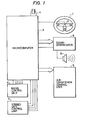
- Fig. 1 is a schematic diagram showing the entire entire structure of an embodiment of the present invention;
- Fig. 2 is an operational flow chart showing the operational processing in the entire microcomputer of Fig. 1;
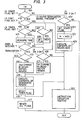
- Fig. 3 is an operational flow chart showing a detailed operational processing in the manipulative control routine of Fig. 2;
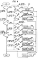
- Fig. 4 is an operational flow chart showing a detailed operational processing of the instruction execution routine of Fig. 3;
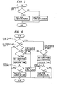
- Fig. 5 is an operational flow chart showing a detailed operational processing of the power instruction routine of Fig. 4;
- Fig. 6 is an operational flow chart showing a detailed operational processing of the sound volume adjustment routine of Fig. 4 ;
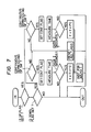
- Fig. 7 is an operational flow chart showing a detailed operational processing of the temperature control instruction routine of Fig. 4;
- Fig. 8 is an operational flow chart showing a detailed operational processing of the airflow rate control instruction routine of Fig. 4;
- Fig. 9 is an operational flow chart showing a detailed operational processing of the air outlet switching routine of Fig. 4; and
- Fig. 10 is a partial structural view of another embodiment.
- The same or corresponding elements and parts are designated at like numerals throughout the drawings.
- Referring now to Fig. 1, a schematic diagram of an embodiment of the present invention is shown. The apparatus of Fig. 1, which is also used to perform the method according to the present invention, generally comprises a normally-open
push button switch 2 attached to the center of thesteering wheel 1 of an unshown motor vehicle, amicrocomputer 3, a sound synthesizer 8 which supplies a vehicle mountedspeaker 9 with synthesized vocal sounds. - The
microcomputer 3 is responsive to a signal from thepush button switch 2, which will be referred to as a manipultive switch hereafter. Themanipulative switch 2 is provided for receiving a demand or instructions from an operator, such as the driver of the motor vehicle. A crystal resonator 4 is shown to be connected to themicrocomputer 3 having unshown central processing unit (CPU), a read-only memory (ROM). a random access memory (RAM), a clock generator, and input/output (I/O) devices. Namely the structure of the microcomputer is of convetional so that it operates in accordance with-a predetermined program stored in the ROM in a well known manner. Themicrocomputer 3 has output terminals connected to the sound synthesizer 8 and to various control units. In the illustrated embodiment, an airconditioner control unit 5, a radio control unit 6 and a stereo unit control unit 7 are shown to be connected to the outputs of themicrocomputer 3. Themicrocomputer 3 also comprises input terminals for receiving signals indicative of the operating state of the radio and the stereo unit. - Although no power source is shown, the
microcomputer 3 is arranged to receive a stabilized voltage via a voltage regulating circuit from the vehicle mounted battery. - In the above-mentioned ROM, are included regions M(0) to M(39) for storing instruction steps shown in the following table.

- The air
conditioner control unit 5 comprises therein an opening degree adjusting actuator for controlling the air mixing damper used for temperature adjustment, a motor drive circuit for driving the blower motor used for sending temperature-adjusted air to the automobile compartment, outlet switching actuator for changing the various operational modes of the temperature-adjusted air outlets. These devices are respectively controlled by various instruction signals from themicrocomputer 3 so as to adjust the air in the automobile compartment. - The radio control unit 6 has a function of turning on and off the power source of the radio in response to a power source on-off instruction signal from the
microcompute 3, a function of adjusting the sound volume in response to a sound volume instruction signal from themicrocomputer 3, and a function of automatically tuning in response to a tuning instruction signal from themicrocomuter 3. The radio control unit 6 is arranged to send a signal indicative of on or off state of the power source of the radio to themicrocomputer 3. - The stereo unit control unit 7 has a function of turning on and off the power source of the stereo unit in response to a power souce on-off instruction signal from the
microcomputer 3, and a function of adjusting the sound volume in response to a sound volume instruction signal from themicrocomputer 3. The stereo unit control unit 7 is arranged to send a signal indicative of on or off state of the power source of the stereo unit to themicrocomputer 3. - The sound synthesizer 8 comprises a vocal sound data ROM for storing vocal sound data, which is used for emitting vocal sounds, in each predetermined region thereof. The sound synthesizer 8 is arranged to synthesize the contents of a predetermined region of the sound data ROM from the first address thereof in response to an instruction signal fed from the
microcomputer 3, namely, in response to an address designation signal designating the first address of the predetermined region, to emit the synthesized vocal sound from thespeaker 9, and is further arranged to send a vocal sound termination signal indicating the termination of sound synthesizing to themicrocomputer 3 when reaching the last . address of the predetermined region. - The operation of the apparatus of Fig. 1 will be described with reference to operational flow charts of Figs. 2 to 9. Fig. 2 is an operational flow chart showing the entire operation of the
microcomputer 3; Fig. 3, an operational flow chart showing detailed operation of the manipulative control operation routine in Fig. 2; Fig. 4, an operational flow chart showing detailed operation of instruction execution routine in Fig. 3; and Figs. 5 to 9, operational flow charts showing detailed operations of respective instruction routines in Fig. 4. - When an unshown key switch is turned on in an automobile comprising the elements or
devices 1 to 9 shown in Fig. 1 at the time of starting operation, electric power is supplied from the automobile battery to respective electrical systems to render the same active. Themicrocomputer 3 starts operating from thestarting step 100 of Fig. 2 to set the registers, counters and latches in themicrocomputer 3 to their initial conditions which are necessary for starting operation. The operation of setting to initial conditions includes a step of resetting all flags, which will be described later, and a step of setting initial values for airflow mode data, blow off mode data and so on. Operation of the main routine, which will be described hereinbelow, comprising an airconditioner control routine 300 and a "manipulative control routine 400 is repeatedly executed at an interval of several hundreds of milliseconds. - In the air
conditioner control routine 300, various instruction signals are sent to the opening degree ajdustor, the motor drive circuit, and to the outlet switching atuator of the airconditioner control unit 5 by executing operational processing for pertinently controlling the air in the automobile compartment, namely by calculating the opening degree of the air mixing damper and the airflow rate data W etc. on the basis of detection signals from various sensors and temperature setting data T preset in a temperature setting circuit and airflow rate and blow off mode data based on mode information preset in an airflow rate and blow off mode setting circuit. The sensors for measuring inner and outer temperatures and for detecting air mixing damper opening degree, and the temperature setting circuit as well as the airflow and blow off mode setting circuits are not shown in Fig. 1 for simplicity. As a result of the operation. instruction signals are fed to the opening degree adjustment actuator of the airconditioner control unit 5, the motor drive circuit and the outlet switching actuator. - In a following manipulative
control operation routine 400, the turn-on signal from themanipulative switch 2 is monitored, which turn-on signal indicates that a deman has occurred for a change in operating conditions of at least one of thedevices 5, 6 and 7. When detecting the turn-on signal during monitoring, the names of various manipulations of the radio, stereo unit and the air conditioner are announced in a predetermined sequence. When another turn-on signal from themanipulative switch 2 is detected, an operation is executed so that an instruction signal is fed to an objective control unit, with which instruction signal of the announced manipulation at the last will be performed. - Fig. 3 shows a detailed operational flow of the
manipulative control routine 400. When reaching themanipulative control routine 400, if themanipulative switch 2 has never been turned on till this time, the answer of a startingflag deciding step 401, which comes first, assumes NO because all the flags used in the manipulative control routine 400 have been reset. Then the operational flow enters into a manipulative switchstate deciding step 402, where the answer thereof assumes NO when themanipulative switch 2 has not been turned on, to terminate one cycle of the operation of themanipulative control routine 400. Ater this. the above-operation is executed whenever reaching the manipulativecontrol operation routine 400 as long as themanipulative switch 2 is not turned on. - After this, when the
manipulative switch 2 is turned on to change the power of the radio from OFF state to ON state, the level of the signal from themanipulative switch 2 "varies to cause the answer of the manipulative switchstate deciding step 402 of Fig. 3 to become YES. Then the operational flow goes to the startingflag setting step 403 to set the starting flag. Then entering into a designationregion setting step 404 to set a designation region M to M(O), and the operational flow goes to anexecution step 405 to execute the contents of the region M(0) of the ROM of themicrocomputer 3. Namely, an instruction signal for announcing "RADIO" according to the ROM table is sent to the sound synthesizer 8, and the operational flow enters into aninstruction execution routine 500. With this operation, the sound synthesizer 8 starts synthesing the vocal sound of "RADIO". - In the
instruction execution routine 500, since all the radio flag, stereo unit flag and the air conditioner flag are left in reset condition, which was done in the initial setting, all the answers of the radioflag deciding step 501, the stereo unitflag deciding step 502 and the air conditionerflag deciding step 503 assume NO to terminate one cycle of the operation. - When the operational flow reaches again the starting
flag deciding step 401 of themanipulative control routine 400 of Fig. 3, the answer thereof becomes YES since the starting flag has been set. Because a continuation flag and a timer flag have been reset from the initial setting, the following continuationflag deciding step 418 and the timerflag deciding step 406 assume NO, and the operational flow enters into a vocal soundtermination deciding step 407 where the answer thereof assumes NO because no vocal sound termination signal has been sent from the sound synthesizer 8. The operational flow enters into a manipulative switchstate deciding step 408 whose answer assumes NO when the manipulative switch has not been turned on again. Thus, the operational flow enters into theinstruction execution routine 500 to execute the above-described operation. - In the case that the vocal sound termination signal is not sent from the sound synthesizer 8 while the
manipulative switch 2 is not turned on again, the above operation is repeatedly executed. When the sound synthesizer 8 completes synthesizing the vocal sound of "RADIO" and produces the vocal sound termination signal, the answer of the vocal soundtermination deciding step 407 becomes YES when the operational flow reaches it. Then the operational flow enters into a timerflag setting step 409 to set the timer flag, and then goes to atime measuring step 410 to measure the time counting the number of times of reaching. As two seconds have not elapsed since entering into thetime measuring step 410, the answer thereof assumes NO to go to the manipulation switchstate deciding step 408. Accordingly, whenever the operational flow reaches the timerflag deciding step 406 from the next time, the operational flow directly goes to thetime measuring step 410 because the timer flag has been set to cause the answer of decision thereof to become YES. Namely, it is made possible to accept responsive instructions via themanipulative switch 2 for the operation of the radio until two senconds will have passed from the emission of the vocal announcement of "RADIO". - When it is recognized by the operator, such as the vehicel driver, that the radio should be manipulated and the
manipulative switch 2 is turned on before the lapse of two senconds, the answer of the manipulationswitch deciding step 408 becoms YES as the operational flow reaches it to enter into a first designationregion changing step 412. In the first designationregion changing step 412, the designation regions are changed by one in connection with the designation region M according to the arrows shown below.
- Since the designation region M by that time has been M(0), the designation region M becomes M(l) after being changed. The operational flow enters into a next execution step 415 to execute the contents of M(l), where the radio flag is set according to the above-mentioned ROM table, and an instruction signal for announcing "TUNING" is sent to the sound synthesizer 8, while the timer flag is set. Then the operational flow goes to the timer flag setting step, and then goes to the
instruction execution routine 500. With this operation, the sound synthesizer 8 starts synthesizing vocal sounds of "TUNING". When the operational flow reaches a radioflag deciding step 501 of theinstruction execution routine 500, the answer thereof becomes YES to go to a tuningflag deciding step 504, powerflag deciding step 505 and to a sound volumeflag deciding step 506. Since all these flags have been reset from the initial setting, all the answers thereof assume NO to complete one cycle of operation. - When the operational flow reaches the timer
flag deciding step 406 of Fig. 3, the answer thereof becomes NO because ot the reset state of the timer flag, and thus the operational flow changes to enter into theinstruction execution routine 500 via the vocal soundtermination deciding step 407 and the manipulative switchstate deciding step 408. When the sound synthesizer 8 completes synthesizing the vocal sound of "TUNING" and produces a sound termination signal, the operational flow goes from the vocal soundtermination deciding step 407 to the timerflag setting step 409 to set the timer flag, and thus, the answer of the timer flag deciding step will be YES from the next time when the operational flow reaches it, and the operational flow goes via thetime measuring step 410,time deciding step 411 and the manipulativeswitch deciding step 408 to theinstruction execution routine 500. - When a period of time of two seconds passes without receiving the turn-on signal from the
manipualative switch 2 with the operator's recognition that the emitted vocal sound of "TUNING" is different from one which is intended to manipulate, the answer of thetime deciding step 411 becomes YES when the operational flow reaches it, and thus the operational flow goes to atermination deciding step 413. In thetermination deciding step 413, it is decided whether or not the designation region M corresponds to one of M(5), M(8), M(13), M(16), M(18), M(22), M(27), M(29), M(38). Thus, the answer of the decision becomes NO because the designation region M by that time is M(l), and therefore, the operational flow goes to a second designation region changing step 414. In the second designation region changing step 414, the designation region M is changed by one in accordance with the following arrows.
- Since the designation region M has been M(l) by that time, the designation region M will be M(3) after being changed. Then the opeational flow goes to a next execution step 415 in which the contents of M(3) are executed, namely, an instruction signal for announcing "POWER" is sent according to the ROM table to the sound synthesizer 8, and the operational flow goes to the
instruction execution routine 500 via a timerflag resetting step 416. With this operation the sound synthesizer 8 starts synthesizing the vocal sound of "POWER" to announce the same. - In the same manner as described in the above, it is monitored, in connection with the announcement of "POWER", to detect if the
manipulative switch 2 is turned on until two senconds elapse. When themanipulative switch 2 is turned on with the operator's recognition that the power source should be turned on in response to the vocal sound emission, the answer of the manipulative switchstate deciding step 408 becomes YES when the operational flow reaches it, and thus the operational flow goes to the first designationregion changing step 412. Since the designation region M has been M(3) by that time, the designation region becomes M(4) after being changed according to the above-described changes. Then in the next executing step 415, the contents of M(4) of the ROM table, namely, the power flag is set. Accordingly, in theinstruction execution routine 500 following the timerflag resetting step 416, when the operational flow reaches the powerflag deciding step 505 of Fig. 4, the answer thereof becomes YES to go to apower instruction routine 513. In thepower instruction routine 513, an instruction signal for the operational processing shown in Fig. 5, i.e. an instruction signal for changing the power condition in accordance with the power on-off state signal from theradio control unit 5, is sent to theradio control unit 5. Entering into an all-flag resetting step 520 of Fig. 4, all the flags necessary for operating processing in the manipulative control routine 400 to complete one cycle of the operation. Therefore, when the operational flow reaches the startingflag deciding step 401 of Fig. 3 next time, which step is encountered first in themanipulative control routine 400, the answer thereof becomes NO to assume the same condition as in the initial condition described in the above. Theradio control unit 5 puts the radio power source in ON state in response to the power-on instruction signal. - In the case that the
manipulative switch 2 is turned on to tune the radio, and then themanipulative switch 2 is again turned on when the vocal sound of OTUNING" is emitted, tuning flag is set because the designation region M is changed to M(2) in the first designatinregion changing step 412. Consequently, when the operational flow reaches the tuningflag deciding step 504, the answer thereof becomes YES to go to thetuning instruction step 512 in which a tuning instruction is sent to theradio control unit 5. With this operation, theradio control unit 5 causes the radio to be tuned. - Suppose the
manipulative switch 2 is turned on to adjust the sound volume of the radio so that the designation region M is changed from M(3) to M(5) in the second designation region changing step 415 after vocal sounds of "RADIO", "TUNING" and "POWER" are emitted. If themanipulative switch 2 is again turned on when the vocal sound of "SOUND VOLUME" is emitted, the designation region M is changed from M(5) to M(6) in the first designationregion changing step 412. Then a sound volume flag is set in the execution step 415 while an intruction for vocal sound of "UP" is sent to the sound synthesizer 8. Therefore, when the operational flow reaches a sound volumeflag deciding step 506 of Fig. 4, the answer thereof becomes YES to go to a sound volumeadjustment instruction routine 514 in which operational processing shown in Fig. 6 is executed, and no sound volume instruction does not occur since none of up flag and down flag has been set. When themanipulative switch 2 is continously depressed to be turned on in response to the emission ot the sound of "UP", the up flag will be set because the designation region M is changed to M(7) in the first designationregion changing step 412. With this -operation. the continuation flag is set and simultaneously, an instruction signal, with which increase by 3dB per one second will result, is sent to theradio control unit 5 in the sound volumeadjustment instruction routine 514 of Fig. 6. As a result, the sound volume of the radio increases more and more. The increase in sound volume stops by cancelling the turn-on state of themanipulative switch 2, and all the flags necessary for operational processing in the manipulative control routine 400 are reset. In order to decrease the sound volume, themanipulative switch 2 may be continously turned on in response to the vocal sound of "DOWN" which is emitted after "UP", so that decrease by 3dB per one second will result in the same manner as described in the above. - Namely, it is possible to emit various vocal sounds in a predetermined sequence in accordance with the contents of the above-mentioned ROM table, the first designation
region changing step 412 and the second designation region changing step 414, while changes in operation in various manipulating elements can be efected by turning on themanipulative switch 2 at an appropriate time. - For instance, in the case of operating the stereo unit, the
manipulative switch 2 is not turned on in response to the emission of the vocal sound of "RADIO", but is turned on in response to the sound of "STEREO UNIT" which is emitted subsequently. Thus, the stereo unit flag is set so that the answer of the stereo unitflag deciding step 502 of Fig. 4 becomes YES. When themanipulative switch 2 is turned on in response to the sound of "POWER" emitted after this, the power flag is set so that the answer of the powerflag deciding step 507 becomes YES when the operational flow reaches it, and the operational flow goes to apower instruction step 515 to produce power on/off instruction signal (this is done by the same operating process as in Fig. 5) to turn on or off the stereo unit. When it is intended to adjust the sound volume rather than the on/off operation of power, themanipulative switch 2 is not manipulated at all in response to the emission of the vocal sound of "POWER", but themanipulative switch 2 is again turned on in response to the sound of "SOUND VOLUME" which is emitted subsequently, the sound volume flag is set to cause the answer of the sound volumeflag deciding step 508 to assume YES when the operational flow reaches it. The operational flow goes to a sound volumeadjustment instruction routine 516 and the same operating processing as in Fig. 6, namely an operating processing for sending an instruction signal with which increase or decrease by 3dB per one second is effected when the manipulative switch is continously turned on in response to "UP" or "DOWN" to the stereo unit control unit 6, is executed. - On the other hand, in the case of operating the air conditioner, the
manipulative switch 2 is not turned on in response to the emission of sounds of "RADIO" and "STEREO UNIT", but is turned on in response to emission of vocal sound "AIR CONDITIONER" which is emitted subseqently, and thus the air conditioner flag is set so that the answer of the air conditionerflag deciding step 503 of Fig. 4 becomes YES. When themanipulative switch 2 is turned on in response to the vocal sound ot "TEMPERATURE" which is emitted subsequently, temperature control flag is set so that the answer of the temperature controlflag deciding step 509 becomes YES when the operational flow reaches it. Thus, the operational flow goes to a temperaturecontrol instruction routine 517 in which the operating processing of Fig. 7 is executed in the same manner as in the case of sound volume adjustment shown in Fig. 6. Namely, when themanipulative switch 2 is continuously depressed to be turned on in response to the emission of the sound of "UP" or "DOWN", the predetermined temperature data T is either raised or lowered by 1 degree centigrade per two seconds, and an instruction signal for emitting the vocal sound of the value of the changed, i.e. raised or lowered, temperature is sent to the sound synthesizer 8. Accordingly, air conditioning is effected so that the temperture in the automobile compartment approaches the changed temperature setting by executing the airconditioner control routine 300 with respect to the changed temperature setting data T. - In the case of adjusting the airflow rate rather than the temperature adjustment, the
manipulative switch 2 is not manipulated at all in response to "TEMPERATURE". Themanipulative switch 2 is turned on in response to the announcement of "AIRFLOW" which is emitted subsequently, and thus an airflow flag is set to cause the answer of an airflowflag deciding step 510 to become YES when this step is encounterd. Then the operaional flow goes to an airflowadjustment instruction routine 518 in which the operational processing shown in Fig. 8 is executed in the same manner as in the cases of Fig. 6 and Fig. 7. Namely, when themanipulative switch 2 is continuously turned on in response to the emission of the sound of "UP" or "DOWN", an operational process is executed to increase or decrease an airflow rate data W by AW per one second. Therefore, the airflow rate is either increased or decreased by executing the opertional process of the airconditioner control routine 300 of Fig. 2 with respect to the changed airflow rate data W. - In the case of changing the air outlets rather than the temperature adjustment and the airflow rate adjustment, the
manipulative switch 2 is not manipulated at all in response to "TEMPERATURE" and "AIRFLOW", but is manipulated again in response to "OUTLETS" emitted subsequently so that outlet flag is set. Therefore, when the operational flow reaches an outletflag deciding step 511, the answer thereof becomes YES to go to an outlet switching routine 519. If themanipulative switch 2 is not manipulated at all after reaching the outlet switching routine 519, vocal sounds of "VENTILATION", "HEATER", "BILEVEL"., "DEFROSTER" and "AUTOMATIC" are emitted one after another. Thus, when themanipulative switch 2 is turned on in response to a vocal sound emission corresponding to an operating mode in which a ch ange should be made, the corresponding flag is set so that an outlet mode data is changed in the operating process of Fig. 9. Accordingly, the outlets are switched in accordance with the changed mode by executing the airconditioner control routine 300 of Fig. 2 with respect to the corrected outlet mode. - On the other hand, when the operational flow reaches the
termination deciding step 413 with the designation region M being M(5), M(8),, M(13), M(16), M(18), M(22), M(27), M(29), M(38), while themanipulative switch 2 has not been turned on again in response to emission of vocal sound of a manipulative element to be changed or the like, namely, when two seconds have elapsed without receving the turn-on signal from themanipulative switch 2 after the emission of one of the vocal sounds of "SOUND VOLUME", "DOWN", "AIR CONDITIONER", "OUTLET" and "AUTOMATIC", the answer of thetermination deciding step 413 becomes YES. Then the operational flow goes to the all-flag resetting step 417 to reset all the flags necessary for operational processing of themanipulative control routine 400, so that the operational processing for manipulative control returns to the above-mentioned initial condition.. - In the above-described embodiment, although the
manipulative switch 2, which is manually operable, is used to produce a demand or instruction signal, it may be possible to receive the demand or instructions from the operator by recognizing the vocal sounds of "CHANGE", "YES" or "NO" of the driver or others by employing asound recognizing circuit 11 with amicrophone 10 provided in the vicinity of the steering wheel as shown in Fig. 10. Thesound recognizer 11 detects a plurality of predetermined vocal words separately to send corresponding recognition signals to themicrocomputer 3. Furthermore, both sound recognition and switch manipulation may used. - Although an example, in which the order of emission of sounds is predetermined, has been described, the order of vocal sound emission may be changed by providing a fast feeding switch or the like, or by arranging such that vocal sound emission takes immediately after the last vocal sound emission. Furthermore, it may be possible to arrange such -that vocal sounds which are needed frequently are emitted preferentially.
- Furthermore, the various manipulative elements to be controlled are not limited to those described in the above, and therefore, they may include wiper switch, head light switch or the like.
- Furthermore, although the sound synthesizer 8 has been described as a vocal announcment emittin means, it is possible to use a device utilizing a magnetic recording tape or the like in which words to be pronounced have been prerecorded.
- From the foregoing description, it will be understood that various devices mounted on a motor vehicle or the like can be readily and accurately controlled by issueing instructions by means of a manually operable switch or by pronouncing predetermined vocal words. Since there is no need to manipulate various switches or keys to turn on, to adjust or to select a desired operating mode of the device which is intended to operate, the vehicle driver can concentrate on driving the vehicle, and thus safe driving can be ensured.
- The above-described embodiments are just examples of the present inventioni and therefore, it will be apparent for those skilled in the art that many modifications and variations may be made without departing from the spirit of the present invention.
Claims (10)
Applications Claiming Priority (2)
| Application Number | Priority Date | Filing Date | Title |
|---|---|---|---|
| JP56032166A JPS57146317A (en) | 1981-03-05 | 1981-03-05 | Method and apparatus for car mounting device |
| JP32166/81 | 1981-03-05 |
Publications (2)
| Publication Number | Publication Date |
|---|---|
| EP0059952A1 true EP0059952A1 (en) | 1982-09-15 |
| EP0059952B1 EP0059952B1 (en) | 1985-10-09 |
Family
ID=12351351
Family Applications (1)
| Application Number | Title | Priority Date | Filing Date |
|---|---|---|---|
| EP82101739A Expired EP0059952B1 (en) | 1981-03-05 | 1982-03-05 | Method and apparatus for controlling a plurality of devices |
Country Status (4)
| Country | Link |
|---|---|
| US (1) | US4503528A (en) |
| EP (1) | EP0059952B1 (en) |
| JP (1) | JPS57146317A (en) |
| DE (1) | DE3266745D1 (en) |
Cited By (8)
| Publication number | Priority date | Publication date | Assignee | Title |
|---|---|---|---|---|
| FR2533513A1 (en) * | 1982-09-23 | 1984-03-30 | Renault | Method and system for communicating, on board a motor vehicle, complex information relating to the vehicle and its environment |
| DE3403836A1 (en) * | 1983-02-04 | 1984-08-16 | Toyoda Gosei Co., Ltd., Haruhimura, Aichi | Remote control system with an actuating device arranged on a steering wheel |
| US4737976A (en) * | 1985-09-03 | 1988-04-12 | Motorola, Inc. | Hands-free control system for a radiotelephone |
| EP0373386A2 (en) * | 1988-12-16 | 1990-06-20 | Robert Bosch Gmbh | Motor vehicle driver information apparatus |
| EP0482315A2 (en) * | 1990-10-20 | 1992-04-29 | GRUNDIG E.M.V. Elektro-Mechanische Versuchsanstalt Max Grundig GmbH & Co. KG | Device for audible signalling of the activated controlled function in an audio device |
| US5133010A (en) * | 1986-01-03 | 1992-07-21 | Motorola, Inc. | Method and apparatus for synthesizing speech without voicing or pitch information |
| GB2267586A (en) * | 1992-06-02 | 1993-12-08 | Amek Systems & Controls Limite | Audible prompt for mixing desk control |
| EP1043193A1 (en) * | 1998-10-26 | 2000-10-11 | Kabushiki Kaisha Tokai-Rika-Denki-Seisakusho | Automatic control system for car accessory |
Families Citing this family (25)
| Publication number | Priority date | Publication date | Assignee | Title |
|---|---|---|---|---|
| JPS59220803A (en) * | 1983-05-30 | 1984-12-12 | Nippon Soken Inc | Operation switch common use device |
| US4677429A (en) * | 1983-12-01 | 1987-06-30 | Navistar International Transportation Corp. | Vehicle information on-board processor |
| IT1187882B (en) * | 1986-01-28 | 1987-12-23 | Fiat Auto Spa | CONTROL SYSTEM AND ACOUSTIC SIGNALING OF FUNCTIONAL CONDITIONS OF A VEHICLE |
| WO1988007796A1 (en) * | 1987-03-31 | 1988-10-06 | Honda Giken Kogyo Kabushiki Kaisha | Radio-signal responsive apparatus for controlling mobile equipment |
| US5068645A (en) * | 1987-10-14 | 1991-11-26 | Wang Laboratories, Inc. | Computer input device using an orientation sensor |
| US4971583A (en) * | 1988-05-31 | 1990-11-20 | Suzuki Jidosha Kogyo Kabushiki Kaisha | Apparatus for outboard engine for switching to voice alarm output |
| US5016003A (en) * | 1988-10-27 | 1991-05-14 | Rice-Kelly Research And Engineering, Inc. | Environmental control system for the handicapped |
| US5525977A (en) * | 1993-12-06 | 1996-06-11 | Prince Corporation | Prompting system for vehicle personalization |
| US5704008A (en) | 1993-12-13 | 1997-12-30 | Lojack Corporation | Method of and apparatus for motor vehicle security assurance employing voice recognition control of vehicle operation |
| US5721541A (en) * | 1995-04-17 | 1998-02-24 | Chrysler Corporation | Remote control assembly for operating audio components in motor vehicle |
| US20070001875A1 (en) * | 1995-11-14 | 2007-01-04 | Taylor William M F | GPS explorer |
| DE19730935C2 (en) * | 1997-07-18 | 2002-12-19 | Siemens Ag | Method for generating a speech output and navigation system |
| DE19825760A1 (en) * | 1998-06-09 | 1999-12-16 | Nokia Mobile Phones Ltd | Procedure for assigning a selectable option to an actuator |
| US6240347B1 (en) | 1998-10-13 | 2001-05-29 | Ford Global Technologies, Inc. | Vehicle accessory control with integrated voice and manual activation |
| US6928614B1 (en) | 1998-10-13 | 2005-08-09 | Visteon Global Technologies, Inc. | Mobile office with speech recognition |
| JP4475796B2 (en) * | 2000-12-08 | 2010-06-09 | 株式会社東海理化電機製作所 | Equipment control device |
| US6571154B2 (en) * | 2001-02-19 | 2003-05-27 | Delphi Technologies, Inc. | Method and apparatus for accessing vehicle systems |
| US6961644B2 (en) | 2002-12-12 | 2005-11-01 | Alps Automotive, Inc. | Dual haptic vehicle control and display system |
| US20050021190A1 (en) * | 2003-07-24 | 2005-01-27 | Worrell Barry C. | Method and apparatus for accessing vehicle systems |
| SE0302831D0 (en) * | 2003-10-27 | 2003-10-27 | Scania Cv Ab | Remote Control System |
| US20070256435A1 (en) * | 2003-12-05 | 2007-11-08 | Kabushikikaisha Kenwood | Air Conditioner Control Device and Air Conditioner Control Method |
| US7697827B2 (en) | 2005-10-17 | 2010-04-13 | Konicek Jeffrey C | User-friendlier interfaces for a camera |
| US20080074286A1 (en) * | 2006-09-21 | 2008-03-27 | Gill Jaspal S | Emergency vehicle alert system and method for using the same |
| DE102007001661A1 (en) * | 2007-01-11 | 2008-07-17 | Enerday Gmbh | Air conditioning for a motor vehicle |
| US7990259B2 (en) * | 2008-01-29 | 2011-08-02 | David Wayne Pobuda | Ignition key with recorded message |
Citations (7)
| Publication number | Priority date | Publication date | Assignee | Title |
|---|---|---|---|---|
| US4060848A (en) * | 1970-12-28 | 1977-11-29 | Gilbert Peter Hyatt | Electronic calculator system having audio messages for operator interaction |
| EP0002435A1 (en) * | 1977-12-14 | 1979-06-27 | Siegfried R. Ruppertsberg | Remote control for controlling and switching variable and fixed functions and parameters in telecommunication equipment |
| GB2026723A (en) * | 1978-01-25 | 1980-02-06 | Tekron Patents Ltd | Circuits for Electric Window Winders for Vehicles |
| FR2437312A1 (en) * | 1978-09-29 | 1980-04-25 | Renault | AIR CONDITIONING DEVICE FOR A MOTOR VEHICLE INTERIOR |
| FR2445769A1 (en) * | 1979-01-04 | 1980-08-01 | Renault | Motor vehicle electrical supply system - includes central control sending signals to microprocessors which switch on required accessories |
| FR2453443A1 (en) * | 1979-04-04 | 1980-10-31 | Hitachi Ltd | METHOD AND APPARATUS FOR CONTROLLING EQUIPMENT OF A MOTOR VEHICLE |
| EP0034373A1 (en) * | 1980-02-18 | 1981-08-26 | Nippondenso Co., Ltd. | Apparatus for controlling an air conditioner for a vehicle |
Family Cites Families (7)
| Publication number | Priority date | Publication date | Assignee | Title |
|---|---|---|---|---|
| JPS5549704A (en) * | 1978-10-04 | 1980-04-10 | Toshiba Corp | Plant operation unit dependent upon voice |
| US4214229A (en) * | 1978-11-16 | 1980-07-22 | Warner William J | Remote control apparatus |
| JPS5577800A (en) * | 1978-12-06 | 1980-06-11 | Nissan Motor | Speech control unit for use in vehicle |
| US4333152A (en) * | 1979-02-05 | 1982-06-01 | Best Robert M | TV Movies that talk back |
| JPS5688503A (en) * | 1979-12-21 | 1981-07-18 | Matsushita Electric Ind Co Ltd | Heater |
| JPS5697337A (en) * | 1979-12-31 | 1981-08-06 | Minolta Camera Co Ltd | Voice control camera |
| JPS57118299A (en) * | 1981-01-14 | 1982-07-23 | Nissan Motor | Voice load driver |
-
1981
- 1981-03-05 JP JP56032166A patent/JPS57146317A/en active Granted
-
1982
- 1982-03-02 US US06/354,045 patent/US4503528A/en not_active Expired - Lifetime
- 1982-03-05 DE DE8282101739T patent/DE3266745D1/en not_active Expired
- 1982-03-05 EP EP82101739A patent/EP0059952B1/en not_active Expired
Patent Citations (7)
| Publication number | Priority date | Publication date | Assignee | Title |
|---|---|---|---|---|
| US4060848A (en) * | 1970-12-28 | 1977-11-29 | Gilbert Peter Hyatt | Electronic calculator system having audio messages for operator interaction |
| EP0002435A1 (en) * | 1977-12-14 | 1979-06-27 | Siegfried R. Ruppertsberg | Remote control for controlling and switching variable and fixed functions and parameters in telecommunication equipment |
| GB2026723A (en) * | 1978-01-25 | 1980-02-06 | Tekron Patents Ltd | Circuits for Electric Window Winders for Vehicles |
| FR2437312A1 (en) * | 1978-09-29 | 1980-04-25 | Renault | AIR CONDITIONING DEVICE FOR A MOTOR VEHICLE INTERIOR |
| FR2445769A1 (en) * | 1979-01-04 | 1980-08-01 | Renault | Motor vehicle electrical supply system - includes central control sending signals to microprocessors which switch on required accessories |
| FR2453443A1 (en) * | 1979-04-04 | 1980-10-31 | Hitachi Ltd | METHOD AND APPARATUS FOR CONTROLLING EQUIPMENT OF A MOTOR VEHICLE |
| EP0034373A1 (en) * | 1980-02-18 | 1981-08-26 | Nippondenso Co., Ltd. | Apparatus for controlling an air conditioner for a vehicle |
Non-Patent Citations (3)
| Title |
|---|
| ELECTRONICA TOP INTERNATIONAAL, vol.4, no.6, June 1979, Bilthoven (NL), 'Auto electronica', pages 10 - 14 * |
| FUNKSCHAU, vol.50, no.14, June 30, 1978, Munchen (DE), D.K. LONG: 'Management von Mikroprozessor-Schnittstellen in der Kraftfahrzeug-Elektronik; 1. Teil', pages 663 - 666 * |
| FUNKSCHAU, vol.50, no.15, July 14, 1978, Munchen (DE), D.K. LONG: 'Management von Mikroprozessor- Schnittstellen in der Kraftfahrzeug-Elektronik; 2. Teil', pages 719 - 721 * |
Cited By (11)
| Publication number | Priority date | Publication date | Assignee | Title |
|---|---|---|---|---|
| FR2533513A1 (en) * | 1982-09-23 | 1984-03-30 | Renault | Method and system for communicating, on board a motor vehicle, complex information relating to the vehicle and its environment |
| DE3403836A1 (en) * | 1983-02-04 | 1984-08-16 | Toyoda Gosei Co., Ltd., Haruhimura, Aichi | Remote control system with an actuating device arranged on a steering wheel |
| US4737976A (en) * | 1985-09-03 | 1988-04-12 | Motorola, Inc. | Hands-free control system for a radiotelephone |
| US5133010A (en) * | 1986-01-03 | 1992-07-21 | Motorola, Inc. | Method and apparatus for synthesizing speech without voicing or pitch information |
| EP0373386A2 (en) * | 1988-12-16 | 1990-06-20 | Robert Bosch Gmbh | Motor vehicle driver information apparatus |
| EP0373386A3 (en) * | 1988-12-16 | 1992-07-01 | Robert Bosch Gmbh | Motor vehicle driver information apparatus |
| EP0482315A2 (en) * | 1990-10-20 | 1992-04-29 | GRUNDIG E.M.V. Elektro-Mechanische Versuchsanstalt Max Grundig GmbH & Co. KG | Device for audible signalling of the activated controlled function in an audio device |
| EP0482315A3 (en) * | 1990-10-20 | 1993-06-30 | Grundig E.M.V. Elektro-Mechanische Versuchsanstalt Max Grundig Hollaend. Stiftung & Co. Kg. | Device for audible signalling of the activated controlled function in an audio device |
| GB2267586A (en) * | 1992-06-02 | 1993-12-08 | Amek Systems & Controls Limite | Audible prompt for mixing desk control |
| EP1043193A1 (en) * | 1998-10-26 | 2000-10-11 | Kabushiki Kaisha Tokai-Rika-Denki-Seisakusho | Automatic control system for car accessory |
| EP1043193A4 (en) * | 1998-10-26 | 2005-06-29 | Tokai Rika Co Ltd | Automatic control system for car accessory |
Also Published As
| Publication number | Publication date |
|---|---|
| DE3266745D1 (en) | 1985-11-14 |
| US4503528A (en) | 1985-03-05 |
| JPS57146317A (en) | 1982-09-09 |
| EP0059952B1 (en) | 1985-10-09 |
| JPH0117166B2 (en) | 1989-03-29 |
Similar Documents
| Publication | Publication Date | Title |
|---|---|---|
| US4503528A (en) | Method and apparatus for controlling vehicle mounted devices and equipment | |
| EP0034373B1 (en) | Apparatus for controlling an air conditioner for a vehicle | |
| US4359713A (en) | Voice warning system with automatic volume adjustment for an automotive vehicle | |
| US6344793B1 (en) | Process for assisting a user of a motor vehicle when operating components of the motor vehicle as well as a pertaining system | |
| US5831514A (en) | Control arrangement for an auxiliary heater in motor vehicles | |
| JP3195395B2 (en) | Improvement of vehicle audio / video device to control mechanism | |
| US5734971A (en) | Adaptive system for determining radio frequency at vehicle start-up | |
| EP0092195A2 (en) | Temperature control unit for vehicular air conditioning unit | |
| US6477498B1 (en) | Method for assignment of a selectable option to an actuating means | |
| JP2001312297A (en) | Voice recognition device | |
| JP3019596B2 (en) | Vehicle air flow control device | |
| JPH0863946A (en) | System integrated with car navigation device and car stereo device | |
| JPS6216843B2 (en) | ||
| JPS56124510A (en) | Controlling method of air conditioning for vehicle | |
| JPS58206415A (en) | Integrated control system of various actuating devices for car | |
| JPS59118517A (en) | Air-conditioning control device for automobile | |
| JPH0645295B2 (en) | Operating device for automobile air conditioner | |
| JP2001142486A (en) | Voice recognition device | |
| JP2000194391A (en) | Voice recognition controller | |
| JPH0582703U (en) | Voice recognizer | |
| JPH1053047A (en) | Information display and control device for automobile | |
| JPS58206443A (en) | United control system for various operation device of vehicle | |
| KR0164737B1 (en) | Remocon receiving voice control method of airconditioner | |
| CN117202031A (en) | Audio playing method, audio playing device, vehicle and storage medium | |
| JPS6022514A (en) | Air conditioner controller |
Legal Events
| Date | Code | Title | Description |
|---|---|---|---|
| PUAI | Public reference made under article 153(3) epc to a published international application that has entered the european phase |
Free format text: ORIGINAL CODE: 0009012 |
|
| AK | Designated contracting states |
Designated state(s): DE FR GB |
|
| 17P | Request for examination filed |
Effective date: 19821021 |
|
| GRAA | (expected) grant |
Free format text: ORIGINAL CODE: 0009210 |
|
| AK | Designated contracting states |
Designated state(s): DE FR GB |
|
| REF | Corresponds to: |
Ref document number: 3266745 Country of ref document: DE Date of ref document: 19851114 |
|
| ET | Fr: translation filed | ||
| PLBE | No opposition filed within time limit |
Free format text: ORIGINAL CODE: 0009261 |
|
| STAA | Information on the status of an ep patent application or granted ep patent |
Free format text: STATUS: NO OPPOSITION FILED WITHIN TIME LIMIT |
|
| 26N | No opposition filed | ||
| REG | Reference to a national code |
Ref country code: GB Ref legal event code: 746 |
|
| REG | Reference to a national code |
Ref country code: FR Ref legal event code: DL |
|
| PGFP | Annual fee paid to national office [announced via postgrant information from national office to epo] |
Ref country code: GB Payment date: 19980224 Year of fee payment: 17 |
|
| PGFP | Annual fee paid to national office [announced via postgrant information from national office to epo] |
Ref country code: FR Payment date: 19980310 Year of fee payment: 17 |
|
| PGFP | Annual fee paid to national office [announced via postgrant information from national office to epo] |
Ref country code: DE Payment date: 19980313 Year of fee payment: 17 |
|
| PG25 | Lapsed in a contracting state [announced via postgrant information from national office to epo] |
Ref country code: GB Free format text: LAPSE BECAUSE OF NON-PAYMENT OF DUE FEES Effective date: 19990305 |
|
| GBPC | Gb: european patent ceased through non-payment of renewal fee |
Effective date: 19990305 |
|
| PG25 | Lapsed in a contracting state [announced via postgrant information from national office to epo] |
Ref country code: FR Free format text: LAPSE BECAUSE OF NON-PAYMENT OF DUE FEES Effective date: 19991130 |
|
| REG | Reference to a national code |
Ref country code: FR Ref legal event code: ST |
|
| PG25 | Lapsed in a contracting state [announced via postgrant information from national office to epo] |
Ref country code: DE Free format text: LAPSE BECAUSE OF NON-PAYMENT OF DUE FEES Effective date: 20000101 |