EP0051018A1 - Method and apparatus for electromagnetic borehole logging - Google Patents
Method and apparatus for electromagnetic borehole logging Download PDFInfo
- Publication number
- EP0051018A1 EP0051018A1 EP81401636A EP81401636A EP0051018A1 EP 0051018 A1 EP0051018 A1 EP 0051018A1 EP 81401636 A EP81401636 A EP 81401636A EP 81401636 A EP81401636 A EP 81401636A EP 0051018 A1 EP0051018 A1 EP 0051018A1
- Authority
- EP
- European Patent Office
- Prior art keywords
- antenna
- probe
- antennas
- conductive
- tool
- Prior art date
- Legal status (The legal status is an assumption and is not a legal conclusion. Google has not performed a legal analysis and makes no representation as to the accuracy of the status listed.)
- Granted
Links
- 238000000034 method Methods 0.000 title claims description 24
- 239000000523 sample Substances 0.000 claims abstract description 42
- 230000015572 biosynthetic process Effects 0.000 claims description 51
- 238000005755 formation reaction Methods 0.000 claims description 51
- 230000005540 biological transmission Effects 0.000 claims description 25
- 238000006243 chemical reaction Methods 0.000 claims description 9
- 230000001902 propagating effect Effects 0.000 claims description 7
- 230000005611 electricity Effects 0.000 claims description 3
- 239000004020 conductor Substances 0.000 abstract description 20
- 238000004519 manufacturing process Methods 0.000 abstract description 10
- 239000003989 dielectric material Substances 0.000 abstract description 9
- 238000005259 measurement Methods 0.000 description 49
- 230000005855 radiation Effects 0.000 description 47
- 238000005553 drilling Methods 0.000 description 33
- 229910052751 metal Inorganic materials 0.000 description 29
- 239000002184 metal Substances 0.000 description 27
- 238000011835 investigation Methods 0.000 description 23
- 230000010363 phase shift Effects 0.000 description 19
- 230000008901 benefit Effects 0.000 description 13
- 238000004804 winding Methods 0.000 description 13
- 239000000463 material Substances 0.000 description 11
- 230000005291 magnetic effect Effects 0.000 description 10
- XLYOFNOQVPJJNP-UHFFFAOYSA-N water Substances O XLYOFNOQVPJJNP-UHFFFAOYSA-N 0.000 description 10
- 238000010586 diagram Methods 0.000 description 9
- 230000000694 effects Effects 0.000 description 9
- 230000035699 permeability Effects 0.000 description 9
- 238000012545 processing Methods 0.000 description 9
- 239000011248 coating agent Substances 0.000 description 7
- 238000000576 coating method Methods 0.000 description 7
- 230000005670 electromagnetic radiation Effects 0.000 description 7
- 239000012530 fluid Substances 0.000 description 7
- 230000006872 improvement Effects 0.000 description 7
- 238000001514 detection method Methods 0.000 description 6
- 239000004459 forage Substances 0.000 description 6
- 230000006698 induction Effects 0.000 description 5
- KWGRBVOPPLSCSI-WPRPVWTQSA-N (-)-ephedrine Chemical compound CN[C@@H](C)[C@H](O)C1=CC=CC=C1 KWGRBVOPPLSCSI-WPRPVWTQSA-N 0.000 description 4
- RYGMFSIKBFXOCR-UHFFFAOYSA-N Copper Chemical compound [Cu] RYGMFSIKBFXOCR-UHFFFAOYSA-N 0.000 description 4
- 239000003990 capacitor Substances 0.000 description 4
- 229910052802 copper Inorganic materials 0.000 description 4
- 239000010949 copper Substances 0.000 description 4
- 230000007423 decrease Effects 0.000 description 4
- 238000012360 testing method Methods 0.000 description 4
- 238000012549 training Methods 0.000 description 4
- 238000005299 abrasion Methods 0.000 description 3
- 230000006978 adaptation Effects 0.000 description 3
- 239000000919 ceramic Substances 0.000 description 3
- 238000013461 design Methods 0.000 description 3
- 239000011152 fibreglass Substances 0.000 description 3
- 230000000644 propagated effect Effects 0.000 description 3
- 239000010802 sludge Substances 0.000 description 3
- 239000000243 solution Substances 0.000 description 3
- 230000009471 action Effects 0.000 description 2
- PNEYBMLMFCGWSK-UHFFFAOYSA-N aluminium oxide Inorganic materials [O-2].[O-2].[O-2].[Al+3].[Al+3] PNEYBMLMFCGWSK-UHFFFAOYSA-N 0.000 description 2
- 238000004458 analytical method Methods 0.000 description 2
- 239000002131 composite material Substances 0.000 description 2
- 230000007797 corrosion Effects 0.000 description 2
- 238000005260 corrosion Methods 0.000 description 2
- 238000005516 engineering process Methods 0.000 description 2
- 230000002349 favourable effect Effects 0.000 description 2
- 230000005294 ferromagnetic effect Effects 0.000 description 2
- 230000004907 flux Effects 0.000 description 2
- 239000011810 insulating material Substances 0.000 description 2
- 239000000696 magnetic material Substances 0.000 description 2
- 239000003208 petroleum Substances 0.000 description 2
- 230000010349 pulsation Effects 0.000 description 2
- 239000011347 resin Substances 0.000 description 2
- 229920005989 resin Polymers 0.000 description 2
- 239000007787 solid Substances 0.000 description 2
- 239000000126 substance Substances 0.000 description 2
- 229910001374 Invar Inorganic materials 0.000 description 1
- 229910000831 Steel Inorganic materials 0.000 description 1
- 229910052782 aluminium Inorganic materials 0.000 description 1
- XAGFODPZIPBFFR-UHFFFAOYSA-N aluminium Chemical compound [Al] XAGFODPZIPBFFR-UHFFFAOYSA-N 0.000 description 1
- 238000003287 bathing Methods 0.000 description 1
- 230000009286 beneficial effect Effects 0.000 description 1
- 230000015556 catabolic process Effects 0.000 description 1
- 238000004891 communication Methods 0.000 description 1
- 230000000295 complement effect Effects 0.000 description 1
- 239000012141 concentrate Substances 0.000 description 1
- 230000003247 decreasing effect Effects 0.000 description 1
- 230000007547 defect Effects 0.000 description 1
- 238000006731 degradation reaction Methods 0.000 description 1
- 230000006866 deterioration Effects 0.000 description 1
- 238000006073 displacement reaction Methods 0.000 description 1
- 230000005684 electric field Effects 0.000 description 1
- 238000004070 electrodeposition Methods 0.000 description 1
- 230000005674 electromagnetic induction Effects 0.000 description 1
- 230000008030 elimination Effects 0.000 description 1
- 238000003379 elimination reaction Methods 0.000 description 1
- 229940082150 encore Drugs 0.000 description 1
- 238000005530 etching Methods 0.000 description 1
- 239000000706 filtrate Substances 0.000 description 1
- 230000017525 heat dissipation Effects 0.000 description 1
- 229930195733 hydrocarbon Natural products 0.000 description 1
- 150000002430 hydrocarbons Chemical class 0.000 description 1
- 230000002706 hydrostatic effect Effects 0.000 description 1
- 230000001976 improved effect Effects 0.000 description 1
- 230000001939 inductive effect Effects 0.000 description 1
- 238000002347 injection Methods 0.000 description 1
- 239000007924 injection Substances 0.000 description 1
- 229910052500 inorganic mineral Inorganic materials 0.000 description 1
- 239000007788 liquid Substances 0.000 description 1
- 230000007774 longterm Effects 0.000 description 1
- 238000012423 maintenance Methods 0.000 description 1
- 238000000691 measurement method Methods 0.000 description 1
- 239000011707 mineral Substances 0.000 description 1
- 230000000116 mitigating effect Effects 0.000 description 1
- 239000012811 non-conductive material Substances 0.000 description 1
- 210000000056 organ Anatomy 0.000 description 1
- 239000002245 particle Substances 0.000 description 1
- 230000002093 peripheral effect Effects 0.000 description 1
- 229920002492 poly(sulfone) Polymers 0.000 description 1
- 239000011148 porous material Substances 0.000 description 1
- 238000003825 pressing Methods 0.000 description 1
- 238000007639 printing Methods 0.000 description 1
- 230000000135 prohibitive effect Effects 0.000 description 1
- 239000011253 protective coating Substances 0.000 description 1
- 230000001681 protective effect Effects 0.000 description 1
- 230000002787 reinforcement Effects 0.000 description 1
- 238000011160 research Methods 0.000 description 1
- 230000004044 response Effects 0.000 description 1
- 230000002441 reversible effect Effects 0.000 description 1
- 150000003839 salts Chemical class 0.000 description 1
- 230000035945 sensitivity Effects 0.000 description 1
- 238000000926 separation method Methods 0.000 description 1
- 230000035939 shock Effects 0.000 description 1
- 238000001228 spectrum Methods 0.000 description 1
- 239000010959 steel Substances 0.000 description 1
- 230000000638 stimulation Effects 0.000 description 1
- 230000008093 supporting effect Effects 0.000 description 1
- 239000000725 suspension Substances 0.000 description 1
Images


Classifications
-
- H—ELECTRICITY
- H01—ELECTRIC ELEMENTS
- H01Q—ANTENNAS, i.e. RADIO AERIALS
- H01Q1/00—Details of, or arrangements associated with, antennas
- H01Q1/36—Structural form of radiating elements, e.g. cone, spiral, umbrella; Particular materials used therewith
- H01Q1/38—Structural form of radiating elements, e.g. cone, spiral, umbrella; Particular materials used therewith formed by a conductive layer on an insulating support
-
- G—PHYSICS
- G01—MEASURING; TESTING
- G01V—GEOPHYSICS; GRAVITATIONAL MEASUREMENTS; DETECTING MASSES OR OBJECTS; TAGS
- G01V3/00—Electric or magnetic prospecting or detecting; Measuring magnetic field characteristics of the earth, e.g. declination, deviation
- G01V3/18—Electric or magnetic prospecting or detecting; Measuring magnetic field characteristics of the earth, e.g. declination, deviation specially adapted for well-logging
- G01V3/30—Electric or magnetic prospecting or detecting; Measuring magnetic field characteristics of the earth, e.g. declination, deviation specially adapted for well-logging operating with electromagnetic waves
Definitions
- the present invention relates to the investigation of underground environments using electromagnetic waves.
- Such measurements call upon various stimulation techniques, including in particular the emission of electromagnetic waves in order to determine certain parameters linked to the behavior of these electromagnetic waves in the medium concerned.
- Embodiments of methods and tools for induction logging are, for example, described in US Patent No. 2,582,314 filed by HC DOLL.
- a transmitter coil mounted on a probe is excited by an oscillator at a frequency of the order of 20 kHz, for example, to induce currents in the surrounding geological formation.
- the importance of these currents depends on the conductivity of the formations in which they originate. They circulate along substantially circular lines centered on the axis of the borehole and themselves cause the appearance of an electromotive force in one or more receiving coils mounted on the logging probe at determined distances from the transmitting coil.
- the analysis of parameters of the output signal of these receiving coils with respect to the signal emitted allows information to be obtained on the conductivity of the formations crossed by these currents.
- radio frequencies are used in a range which can range from a low frequency of about 1 megahertz to about one gigahertz.
- the value of the dielectric constant of the medium concerned has a decisive influence on the attenuation and phase shift measurements at the expense of the conductivity, the influence of which on the measurements is increasingly weaker as as the frequency rises.
- the combination of attenuation and phase shift measures makes it possible to completely eliminate the influence of this last factor to determine the dielectric constant or electrical permittivity of the media concerned.
- electromagnetic logging tools provided with transmitter and receivers mounted on a mandrel at distances which can be of the order of a meter or more to obtain measurements of interest in areas located at a radial distance greater than a meter from to the drilling axis.
- Such a tool is described in United States Patent 4,185,238 of January 22, 1980 (HUCHITAL and TABANOU). It includes: a transmitter at the bottom of its own mandrel to operate at a determined frequency; a first pair of longitudinally spaced receivers, the midpoint of which is at a first distance from the transmitter for carrying out a measurement of relative attenuation of the signals coming from the transmitter through the surrounding medium; and a second pair of longitudinally spaced receivers, the midpoint of which is at a second distance from the transmitter, greater than the first distance, for carrying out a measurement of phase shift or of relative phase between the signals which reach them.
- the first and second distances are selected such that the attenuation and phase shift measurements made by the first and second pairs of receivers respectively concern the same area of the formation. It has in fact been determined that the relative attenuation and phase measurements of waves propagating through the formations were affected in a different manner by the distance between the zone concerned and the axis of the hole. Thus, to obtain measurements of the phase shift caused by the propagation of the waves in a training area tion at a determined distance from the borehole, a pair of receivers must be used located at a greater distance from the transmitter than that which separates it from the pair of receivers intended for wave attenuation measurements in this same area.
- the radiation transducers, transmitters or receivers, used for electromagnetic propagation logging must meet certain conditions. In particular, they must be adapted to the transmission of energy in highly dissipative media, that is to say where it is accompanied by considerable losses. In emission, these transducers must therefore be capable of transmitting significant amounts of energy to the surrounding environment; on reception, they must on the contrary be capable of picking up signal levels which are sometimes extremely weak. Furthermore, these transducers must have particular characteristics of directivity. In general, research is carried out in electromagnetic logging techniques to promote the propagation of waves in the direction of formations at the expense of the propagation of these waves longitudinally in the borehole. It is therefore important to provide that the transducers used for this purpose have well-defined directivity characteristics.
- each receiver forms with the transmitter the frames of a capacitor, the dielectric of which is formed by the surrounding medium.
- these transducers are mounted like antennas on the mandrel and the investigation frequency used is located at the bottom of the radio frequency range.
- this technique does not allow satisfactory results to be obtained, in particular because the antennas are short-circuited by the drilling fluid when the latter is, as is frequent, a relatively conductive medium. In these conditions, it is not possible to obtain nir an efficient transmission of electromagnetic energy in the formation that one seeks to study.
- the transmitters and receivers used for the transmission of electromagnetic waves between the tool and the surrounding medium are toroidal coils whose axis is directed along the axis of the mandrel of the drilling tool.
- coils are also used for the emission and reception of electromagnetic waves . These coils work like dipoles which have good directivity.
- coils make it possible to remedy to a certain extent the faults reported about the antennas forming capacitor plates.
- these coils are capable of operating in slightly conductive drilling fluids.
- this improvement has limits and that the level of the signals which reach the receivers after propagation through the formations concerned is often extremely low.
- antennas constituted by a dielectric plate on one face of which is printed an elongated conductive element while its other face is metallized to form a second conductive element or plane of mass.
- These antennas known as two-plate lines use techniques for manufacturing printed circuits. They have the advantage of being able to be relatively easily shaped to the shape of air or space vehicles in a relatively small volume. They have proven to be well suited to omnidirectional type transmissions in air or vacuum where the propagation of electromagnetic waves is practically carried out without loss. The performance of antennas of this nature, which increases as the square of their frequency of use, is acceptable in the application to telecommunications at frequencies of several hundred megahertz.
- transmission and “transmit” will be used in relation to the propagation of a radiation in a medium indifferently with regard to the emission and the reception of this radiation by a transducer immersed in this medium.
- One of the objects of the present invention is to improve the performance of electromagnetic logging tools, in particular by making it possible to increase the power of the radiation transmitted by these tools for measurement purposes under the conditions of use prevailing in the boreholes.
- a logging tool suitable for being moved in a borehole crossing geological formations for measuring the propagation characteristics of an electromagnetic wave in the surrounding medium, comprises a probe and means associated with this. probe: for emitting electromagnetic energy towards the surrounding medium and for detecting part of this energy after its propagation in said medium, and, is characterized in that said means comprise at least one antenna comprising a first elongated conductor of electricity and a second conductive element disposed opposite and at a distance from the first element over the entire useful length of the latter, the opposite portions of the first and second elements being separated by a non-conductive medium and electrically connected to each other at one end of the useful length of the first element.
- the invention relates to the logging method in which such an antenna is implemented.
- a radiation transducer is used real antenna that can preferably be tuned depending on the frequency of the radiation to be transmitted.
- the electrical connection between the two elements is a short circuit and the useful length of the first element is granted as a function of the wavelength of propagation of said electromagnetic energy in the non-conducting medium. .
- the antennas which have just been defined could be advantageously adapted for use in logging tools for emitting or receiving radiation in the environment of a borehole with performance in terms of much higher yield. to those which were accessible with the radiating systems of the prior art in this field.
- Such antennas can be produced in the so-called bi-plate line technology according to which the first elongated conductive element is printed on one face of a plate of insulating material, while the other face is metallized to form the second conductive element or ground plan.
- this technology has been used to form antennas suitable for the omnidirectional transmission of electromagnetic radiation in non-dissipative media such as air or vacuum, that is to say in which the propagation of these waves are practically lossless, which is essential for the transmission of information.
- the non-conductive medium is a plate of dielectric material.
- the non-conductive material is a magnetic material with high magnetic permeability.
- the impedance of each antenna is adapted to the impedance of a coaxial link which connects it to electronic circuits by adjusting the position of the connection point of the core of this coaxial link along the first conductive element.
- the antennas are mounted on tool chucks. It is therefore particularly advantageous to have the first conductive element around this mandrel to reduce its mechanical length parallel to the longitudinal dimension of the latter, while the second element extends over two dimensions by forming a cylindrical mass element disposed at the inside the first. This second element can then act as a screen vis-à-vis the first against the disturbing influences of the signals inside the probe, for example of the supply current of an oscillator supplying the transmitter. It is possible, in particular, to extend this second element beyond the antenna, so as to form a continuous screen tube along the probe inside which the supply conductors of the tool circuits pass. . In addition, various embodiments are then provided to improve the protection of the antenna, while minimizing or eliminating the propagation of electromagnetic energy in transverse mode (TEM mode) from the transmitter to the receivers and to obtain a better arrangement of the internal space of the tool.
- TEM mode electromagnetic energy in transverse mode
- the second element of the antenna forms a cylindrical element of mass inside the first element
- the probe is then advantageously formed by a tubular steel body, a portion of which is used to form the second element of the antenna, which is covered with a dielectric material which supports the first element or radiating element of the antenna.
- a metal electrode for current conduction through the formation is equipped for resistivity measurements with an antenna of the type indicated above in which the second conductive element is electrically linked with the body of the electrode.
- the tools provided with antennas of the indicated type allow an investigation of the environments surrounding a borehole in which the resistivity of the drilling mud is significantly lower than that which was considered until now as minimal for the correct operation of tools for electromagnetic propagation. They also have various advantages in terms of the physical production of such tools, in particular their design, both exterior and interior.
- the antennas defined above apply particularly well to the mounting on mandrels of deep investigation tools which are intended to operate at frequencies of a few tens of megahertz, like the tools with coils described above.
- these antennas could advantageously also be applied to electromagnetic logging tools in the relatively low frequency range, below 10 megahertz for example, especially when a material with high magnetic permeability is used between the two conductive elements of the antenna, as well as in the higher frequency range, above 200 megahertz for example.
- antennas suitable for being mounted on pads are produced in a simple manner.
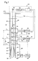
- the tool 30 comprises an elongated probe body or mandrel 40 suspended by its upper end 42 to the cable 32 and which comprises an outer casing 44 suitable for isolating the functional parts of the drilling tool 20.
- a transmitter 50 T
- a transmitter 50 T
- a first pair of receiving antennas 51 and 52 R1 and R2 vertically spaced at a predetermined distance.
- the distance between the emitter 50 (T) and the medium L'2 of the interval separating the receptors R1 and R2 is marked by D n .
- this pair of antennas is mounted, on the mandrel 40, another pair of spaced apart longitudinal receiving antennas 53 and 54 (R3 and R4).
- the middle L ' 3 of the interval between these antennas is located at a distance D f from the transmitter 50 greater than D n .
- the transmitter 50 is capable of emitting an electromagnetic wave in a dihedral of 360 ° around the axis of the mandrel 40. It is supplied from an oscillator 60 housed inside the envelope 44 via a coaxial link 62. The oscillator 60 also controls an oscillator 64 capable of operating at a slightly higher or slightly lower frequency (a few tens of kilo hertz apart).
- the receivers 51, 52 are capable of detecting electromagnetic radiation which reaches them after having propagated through the formations 22 in a dihedral of 360 ° around the axis of the borehole 20. They are connected to an amplitude comparator 66 receiving the output frequency of the oscillator 64 on an input 67 ..
- the receivers 53 and 54 (R3 and R4) are connected to the inputs of a relative phase detector 68 which receives on an input 69 the output frequency of the oscillator 64.
- the receiving antennas 51, 52 are connected to the amplitude comparator 66 by coaxial cables 56 and 58 respectively on the receiving antennas 53 and 54 are connected to the phase detector 68 by coaxial cables 55 and 57 respectively.
- the two circuits 66 and 68 each include a mixer of signals from the oscillator 64 and signals received from the antennas 51, 52 and 53, 54 respectively, in order to derive therefrom a signal whose frequency is relatively low (a few tens of kilo hertz), to determine on the one hand the difference in amplitude of the signals received by the receivers R1 and R2 and, on the other hand, their phase shift from the signals received by the receivers R3 and R4.
- the two corresponding pieces of information are available at the outputs 70 and 71 of the circuits 66 and 68, respectively and are transmitted to the surface by the cable 32 to a processing member 72 suitable for supplying the recorder 38 with logging signals representing by example the dielectric constant and / or the conductivity of the formations interested in the propagation of the waves emitted by the transmitter 50.
- the cable 32 also ensures the power supply of the oscillators 60 and 64, as well as of the electronic circuits 66 and 68 which are housed in the tool or in the probe 40.
- the transmitters 50 and the receivers 51 and 52 are generally constituted by coils comprising a small number of turns, for example two, mounted on an insulating sleeve such as a ceramic.
- these efforts come up against limits in the dimensioning of drilling tools and in the electrical powers which can be used in a tool connected to the end of a cable several thousand meters long. .
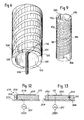
- An antenna 99 of the two-plate type is formed by the combination of two metallic elements plated on either side of a dielectric according to a technique which is similar to the manufacture of printed circuits.
- a plac e to p planar dielectric 100 comprises on one of its faces 101 a conductive strip 102 made of copper, of curvilinear shape in this example, printed in the dielectric 100. This dielectric may for example be a high temperature ceramic.
- the opposite face 103 to the face 101 of the plate 100 is entirely covered with a metallic coating 105, for example made of copper, aluminum or invar.
- One end 106 of the metal strip 102 is electrically connected to the metal sheet 105 by a short-circuit link 108 through the dielectric 100.
- a coaxial cable 109 reaches the antenna 99 from the side of its underside 103.
- the sheath of this coaxial cable l09 is electrically connected to the plate 105 while its core, after having passed through the dielectric, is welded to the blade l02 at a point 110 placed at a predetermined distance from the end 106.
- the blade l02 has a length curvilinear on the plate 100 between its end 106 and its other end left electrically free (represented at 107 in FIG. 4), equal in this example to a quarter of the wavelength of propagation of the operating frequency of l 'antenna.
- the sheet 105 is generally designated by the name of the trap plane, the strip 102 being considered as forming the radiating element proper.
- antennas comprising a first and a second metal elements facing each other such as the strip 102 and the sheet 105, separated by a non-conducting medium constituted, for example, by a solid plate of a material dielectric 100. These elements are electrically connected at one of their ends, the length of the first element being determined as a function of the wavelength with which the electromagnetic signals propagate in the dielectric separating the two conductive elements at the frequency considered.
- the length of an antenna transmitting electromagnetic radiation is equal to a quarter of the wavelength of this radiation, or to a multiple of the latter, the input impedance of this antenna is purely real, which is a condition for optimal performance of this antenna.
- the conductive elements separated by the dielectric are arranged opposite; on the other hand, it is not essential for their operation that the second conductive element, corresponding in the example of FIG. 3 to the plate 105, extends over a surface. It is possible to produce antennas in which the second conductor is also an elongated element following a path substantially parallel to that of the first conductor and arranged opposite the latter. The arrangement that this second element extends in two dimensions along a plane or a mass surface has a number of advantages, some of which will be discussed below.
- the antenna operating frequency is relatively low, for example of the order of a few tens of megahertz, a quarter of the corresponding wavelength in air represents a relatively large length compared to the dimensions of the tools. well logging. In the case of a frequency of 25 megahertz, a quarter of the wavelength of the propagation of radiation in the air is equal to about 3 meters.
- the antenna instead of being mounted in air, is placed in a dielectric material ( Figure 3 for example), the wavelength radiated in this dielectric for a determined frequency is less than that of the radiation in the due to the higher value of the dielectric constant of the material.
- the electrical permittivity ⁇ of the dielectric material on which the first element is printed is greater than 1, that is to say the permittivity of air or vacuum, the propagation wavelength of the radiation in this medium decreases as a function of the square root of this permittivity.
- the corresponding wavelength will therefore be approximately half that of propagation of the radiation at the same frequency in air. It follows that the length of an antenna tuned to a quarter or a half wavelength can be halved when this antenna is placed in a dielectric. Under these conditions, at 25 megahertz, the antenna length necessary to obtain a good transmission efficiency in this dielectric is equal to 1.5 meters.
- Various arrangements are provided for making these antennas in a minimal space requirement on a drilling logging tool.
- the frequency of the signals to be transmitted increases, the corresponding wavelength decreases and it is then possible to consider giving the antenna lengths equal to half a wavelength of the radiation in the dielectric. In the latter case, the two ends of the first element such as l02 are short-circuited with the ground plane 105.
- the frequency of the electromagnetic waves to be transmitted increases, it is possible to increase the length of the antenna relative to the wavelength in the dielectric, for a given bulk, which is, in all cases, a factor for improving the efficiency.
- these antennas In the air, these antennas have an efficiency which increases like the square of the transmitted frequency. When used in the context of space or air telecommunications, they involve frequencies of several hundred megahertz with a performance which, although less good than that of conventional aerial antennas, is however acceptable for the needs of communications by transmission. in a non-dissipative medium. However, tests have shown that these antennas could be used with excellent performance in the environment of boreholes at frequencies much lower than their current frequency of use in air or vacuum. This is particularly the case at frequencies of a few tens of megahertz corresponding to the frequencies used in professional tools electromagnetic deep investigation paging.
- the energy of the radiation received or emitted by an antenna is of an active nature.
- radiation resistance R r the value of the fictitious resistance which would produce a heat dissipation of energy equivalent to the radiated energy.
- the efficiency ⁇ of the antenna can be characterized by considering, on the one hand, the radiation resistance corresponding to a useful energy transmission and, on the other hand, a loss resistance R:
- the dielectric constant of water ⁇ r is equal to approximately 80, which amounts to saying that the resistance R in water is approximately 80 times stronger than in air. It follows that for a determined efficiency n of the antenna in air, the corresponding efficiency of the same antenna in water is very substantially higher and close to 1 insofar as the loss resistors R which have not changed can then be considered negligible compared to the radiation resistance of the antenna in water.
- the relation (V) is valid for a nonconductive medium.
- the consideration of the relation (II) defining the propagation constant makes it possible to note that if the conductivity c of the surrounding medium in the antenna is not zero, the propagation wavelength tends to decrease further compared to at its value in a non-conductive medium.
- antennas of the general type considered previously could effectively be adapted to the specific conditions of their use on logging tools.
- these antennas can be shaped as a function of the space constraints of these tools and give them a certain directivity in order to favor transmissions of radiant energy in directions transverse to the direction of drilling.
- the plate of insulating material can be mounted so that one of its faces on which the first conductive element is printed appears on the surface of the tool, either on a mandrel or on a shoe.
- This conductive element can be wound up if necessary on the surface of this mandrel or of this shoe in order to give the antenna the desired electrical length while maintaining its mechanical length in dimensions compatible with those of the tool.
- this mechanical length can be adapted as a function of the directivity characteristics provided for the tool.
- the directivity of an antenna depends on the phase shifts of the currents per unit of mechanical length along this antenna.
- the antenna length is sufficient to obtain current phase shifts which favor the action of the antenna in certain directions at the expense of others, which is obtained in particular by providing a mechanical length of the antenna of the order of magnitude of the wavelength of the radiation in the medium external to the antenna.
- a radiation transducer such as the emitter 50 formed by a coil 81 can be represented by the equivalent diagram of a self inductance 80 in series with a resistor 82 connected to the output of a coaxial cable 84 supplied by an oscillator 86.
- the impedance of such a coil 81 is very highly reactive due to the high value of the inductor 80, while the coaxial link 84 intended to supply this coil is designed to transmit a energy to radiate of an essentially active nature.
- the radiation transducers of the type considered in accordance with the invention constitute real antennas, the length of which can be tuned as a function of the frequency of the radiation that they are called upon to transmit so as to give them essentially an impedance. active, condition of a good performance of their operation.
- the impedance of these antennas is very weakly reactive, unlike the case of coils; and this result can be achieved thanks to the arrangements indicated above, with dimensions compatible with those of the tools intended to be used in the boreholes.
- This essentially active impedance has advantages not only for establishing a condition of resonance favorable to the conversion of electrical energy into electromagnetic energy by the antenna proper, but also in terms of the efficiency of the transmission of electrical energy along the coaxial link connecting the antenna to its associated electronic circuit. Losses if- g n alées previously in coils are avoided effect.
- antennas also offer the possibility of carrying out, in a very simple manner, an impedance adaptation of the antenna to the impedance of the coaxial cable which connects it to the electronic circuits for supplying or processing the signals.
- FIG. 4 A diagram of a developed longitudinal section view of a two-plate antenna is given in FIG. 4 in which the same references have been used as in FIG. 3.
- An oscillator l12 is connected to one end l13 of the coaxial link 109 whose the other end is connected by its sheath 114 to the ground plane 105, perpendicularly to the latter, the core 115 of this connection being isolated from the ground plane 105 and passing through the dielectric 100 to reach the junction point 110.
- the ground plane 105 constitutes an electrical screen between the blade 102 constituting the sensitive part of the antenna 110 and the electronic circuits located behind the ground plane.
- junction point 110 of the core 115 of the coaxial l09 is located at a distance d from the short-circuited end 106 of this antenna 99, which is chosen to carry out an impedance adaptation by making the element play 102 the role of an auto-transformer, as it will be explained.
- a diagram equivalent to the antenna 99, represented in FIG. 5, comprises, between the ends 106 and 107 of the strip 102, a wound coil L whose number of turns corresponds to the length of this strip and a capacity C equivalent to the capacitive link existing between the blade 102 and the ground plane 105.
- the ground plane 105 is connected to ground.
- the LC circuit in parallel represents a resonant circuit equivalent to the antenna. For an antenna length equal to a quarter of the wavelength radiated in the dielectric, the impedances of the circuit containing the self L and of the circuit containing the capacitance C correspond to the resonance condition which allows the optimal conversion of electrical energy into radiant energy.
- the junction point 110 is an intermediate point of the choke which corresponds to a number of turns ni of this choke between the ground plane 105 and the junction 110, n t being the total number of turns of the choke L.
- the position of the junction 110 is chosen so that the quantity (n i / n t ) 2 x R is substantially equal to the impedance of the coaxial connecting line 109.
- the self L plays the role of a self-transformer whose can calculate the impedance reported at the input, i.e. (n i / n t ) 2 x R. If this impedance is equal to the impedance of the coaxial line used with the antenna, energy losses are completely eliminated by reflection in the coaxial, which contributes to obtaining a good efficiency of the antenna.
- biplate type antennas The potential increase in the power available in the environment specific to logging tools in boreholes which results from the use of biplate type antennas has very important consequences for the applications and the realization of such logging tools.
- electromagnetic logging In addition, certain technological features of bi-plate antennas have other advantageous consequences which will be examined below in connection with various embodiments and use of antennas for electromagnetic logging tools.
- a first conductive element 124 of the antenna is wound in the form of a helix of regular pitch around a cylindrical sleeve 120, of dielectric material, the internal face of which is upholstered by a conductive sheet 126 forming the second conductive element or ground element.
- the conductive element 124 is a copper strip printed in the surface 122 of the sleeve 120 over a developed length equal to a quarter of the wavelength of propagation of the radiation at the frequency considered in the material constituting this sleeve 120.
- the pitch of the winding of the blade 124 is relatively tight and the longitudinal spacing between the turns of this blade is substantially less, as shown, than the width of this blade 124.
- the sleeve is made of a ceramic or a composite material based on fiberglass and resin.
- the blade 124 is implanted there according to a conventional printing technique of the type used in the production of a printed circuit, and for example by etching or electrodeposition.
- the lower end 128 of the first element 124 is electrically connected to a power source at high frequency by a coaxial link 130 having a core connected at a point 132 of the internal face of the helical blade 124 (that is to say its face in contact with the dielectric 120).
- the core of this coaxial connection crosses this dielectric perpendicular to the internal surface of the dielectric sleeve 120, the sheath of the coaxial being connected to the cylindrical mass element 126.
- an antenna is suitable for being mounted coaxially with the mandrel of a drilling tool such as that shown in FIG. 1 to constitute the transmission 50 and reception 51 and 52 elements.
- an antenna produced at this effect comprises eight turns of a metal blade one-tenth of a millimeter thick of copper whose width (dimension measured in the axial direction) is 5 mm, the pitch of the propeller being 7.5 millimeters, on a sleeve with an external diameter of 8 cm.
- the internal surface of the sleeve is lined with a metal sheet one millimeter thick forming a ground plane.
- the insulating sleeve consists of a polysulfone and has a thickness of 5 millimeters.
- the antenna tuned to the quarter of the wavelength of the wave of propagation of this frequency in the dielectric material of the sleeve 120 has a developed length of approximately 2 meters and a total length in the axial direction or mechanical length of 6 centimeters. Measurements of the yield obtained with such an antenna operating in salt water provided values of the order of 90%, that is to say of an order of magnitude incommensurate with what was conceivable with the front coils.
- the resonance condition of this antenna is met without any other particular arrangement and in particular without the need to provide circuits for special agreements.
- Such circuits were necessary with coil transducers to allow the circuit of the latter in the resonance condition.
- the elimination of these tuning circuits is an advantage because they are difficult to manufacture and subject to radiant energy leaks and they occupy a non-negligible space in the tool.
- the transmitting antenna and the receiving antennas are separated by portions of insulating tubes to which they are connected by suitable means, for example by connection sleeves. According to another arrangement, these antennas are arranged around a common internal insulating sleeve supported longitudinally in the mandrel 40. According to a variant, the casing 44 of the probe body is formed, at least over part of its length, by a extension of an antenna sleeve such as 120 (FIG. 6) over the useful height of the mandrel, the same sleeve then serving as a support for the first and second conductive elements of the various transmitting and receiving antennas.
- an antenna sleeve such as 120 (FIG. 6)
- the mass elements such as 126 which constitute the second element of each of the antennas T , Rl , R2 ( Figure 1) are part of a single conductive cylindrical sleeve extending over the entire height.
- This arrangement has the advantage that the conductive sleeve thus formed inside the tool acts as a screen with respect to the transmitting and receiving antennas vis-à-vis all disturbing signals circulating in conductors inside the body of the tool, such as, for example, the supply current of the oscillator 60 which generates the power to be emitted in the formations.
- the electromagnetic propagation tools include electronics for processing the signals picked up by the receiving antennas R1 to R4 ( Figure 1) which must be located, in particular because of the low level of these signals near these receivers.
- This electronics is normally housed either at the upper part of the probe body 40 , or in a specially fitted box above this probe body to which the cable 32 is attached.
- the transmitter T must therefore be located below the receiver towards the lower part of the tool 30 and its power oscillator 60 must be placed nearby in order to limit the length of the coaxial link 62 which supplies it.
- a solution envisaged and applied in certain cases to avoid this problem is to supply this oscillator 60 with a battery during the measurement periods when the transmitter transmits radiation towards the formations, this battery then being suitable for being recharged outside the periods of operation of electromagnetic detection.
- this solution requires the use of a battery in the difficult environment in which the logging tools have to work in the boreholes, by exposing it in particular to very high temperatures. It has the disadvantage of a certain fragility, an insufficient energy reserve for long-term logging operations. and reliability questionable. In the absence of this solution, it is advisable to surround the conductors which supply the oscillator from the tool suspension cable with a screen produced by a longitudinal metal tube passing through the probe to the oscillator 60.
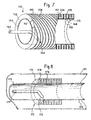
- This mass cylinder 154 is wound, electrical contact with this cylinder, on its.
- a metal strip 156 which is placed on the field in a plane approximately perpendicular to the surface of the cylinder 154 and wound in a helix around the latter over a length of sleeve 152 corresponding to the length of the antenna.
- the outer edge 157 of the strip 156 is flush with the outer surface 160 of the dielectric sleeve 152.
- a conductive metal strip 158 forming the first element of the antenna is helically wound in the thickness of the sleeve 152 by forming turns arranged on the field and interposed between the turns of the ground element 156 and whose outer edge 159 is flush with the outer surface 160 of the dielectric sleeve 152.
- the strip 158 is electrically connected at one of its ends 162 to the metal coating 154 internally sheathing the sleeve dielectric 152.
- the antenna thus formed is connected to a coaxial cable 164, one end of which is perpendicular to the internal surface of the sleeve 152.
- the sheath of this cable is electrically connected to the ground cylinder 154 and the core of this conductor is connected to the strip 158 ′ at a point 166 at a suitable distance from the end 162 along this winding, to carry out the impedance matching of which it has been spoken.
- the helical winding of the strip 158 extends over a distance along the cylinder 152 corresponding to the developed length of the desired antenna.
- This arrangement makes it possible to reduce the transmissions of electromagnetic energy in a direction parallel to the axis of the mandrel 44.
- the formation of waves capable of propagating in TEM mode inside the coaxial link defined above is mainly based on the existence of a capacitance distributed between the turns of the first wound antenna element 158 and the column of mud surrounding the tool. The value of this capacity depends on the effective surfaces of the facing reinforcements. In the case of FIG. 7, the surface of the edge of the turns 158 which are located opposite the column of mud is very small and therefore contributes minimally to the formation of waves transmitted according to the TEM mode.
- a metal sleeve 170 is placed inside the insulating envelope 171 of an electromagnetic logging tool mandrel (FIG. 8), in the extension of the cylindrical mass element 172 of an antenna 173 of the biplate type. with field conductors 176 and 178, similar to the antenna shown in FIG. 7.
- the metal conductor on wafer 178 is embedded in the dielectric 175 and is electrically connected by its internal wafer to the ground cylinder 172. Power is supplied as before by a coaxial cable 179.
- the first element of the antenna is preferably wound in a helix (FIG. 9 ) form of two longitudinal portions wound in equal steps and in opposite directions.
- a dielectric sleeve 192 whose inner part is sheathed with a metallic coating 193 forming a cylindrical mass element, an external metallic blade 194 is wound in a helix, starting from one end 195 short-circuited with the cylinder of mass 193, in one direction to a turning point 196 corresponding to half the developed length of the antenna, from which the pitch of the winding reverses to form the turns 197.
- the end 198 of this radiating element is short-circuited with the ground plane.
- the total length of the antenna is tuned to half the wavelength envisaged in the dielectric 192. It is supplied at two points close to its ends 195 and 198 respectively by two coaxial cables under two voltages in phase opposition. We therefore obtain two quarter wave antennas in series, geometrically opposite, but in which the current is in the same direction, which favors radiation in desired mode, while the electric fields corresponding to the voltage between each of the winding portions. reverse steps and the column of mud are of different signs and have opposite effects which tend to cancel the transmission in TEM mode.
- a probe 200 (FIG. 10) comprises a cylindrical mandrel surrounded by an external metal casing 202. Around this envelope are arranged, in several longitudinally spaced locations 204, two-plate antennas 206 of the winding type according to the embodiment of FIG. 6. As shown in the upper part of FIG. 10 which shows the probe partially cut by a longitudinal diametral plane, the metallic outer casing 202 has, at each location 204, a portion 208 of narrowed outer diameter which in itself constitutes a cylindrical element of mass for each antenna 206.
- Each of these narrowed portions 208 is coated with a dielectric sleeve 209 around which a helical metal blade 210 is wound, one end of which is short-circuited with the narrowed metal part 208 of the conductive envelope 202.
- the combined thickness of the dielectric 209 and of the winding 210 is such that the diameter of the assembly is less than the diameter of the envelope 202 in the parts 212 which separate the locations 204.
- These portions 212 are interconnected by a series of bars 214 of longitudinal direction passing over each winding 210 which thus form a cage with parallel bars around the antennas 206 for the purpose of mechanical protection.
- the longitudinal bars 214 are integral with the casing 202.
- the cylindrical mass element of the antennas is in direct electrical contact with the mud 202. No propagation in TEM mode can take place in the absence of a structure of the coaxial type with dielectric between an internal conductor and the column of mud surrounding the tool.
- the envelope of a probe 220 is constituted by a cylindrical metal tube 222 extending over the entire height of the tool.
- a transmitting antenna 224 at the bottom of the tool and a series of receiving antennas 226 1 , 226 2 , 226 3 and 226 4 "
- Each of the antennas 224 , 226 1 to 226 4 comprises a dielectric coating 229 directly attached around the external surface of the envelope 222, which forms a cylindrical element of mass common to all these antennas.
- dielectric sleeve 229 FIG.
- the winding 230 is embedded in an insulating coating 232 based on fiberglass which gives it both mechanical protection against shocks and abrasion due to movement of the tool inside the borehole and chemical against corrosion.
- the core 235 is connected as previously described to carry out the impedance matching.
- the protection offered by the coating 232 is effective from a mechanical and chemical point of view, it is not essential from an electrical point of view. No propagation in TEM mode is to be feared.
- Supports 240 mount electronic processing cards suitable for being connected to pairs of receivers 226 1 , 226 2 and 226 3 , 226 4 via coaxial cables 241, 243, 245 and 246.
- an electromagnetic wave propagation logging probe comprising a metal envelope which, in addition to suppressing the propagation of waves in TEM mode, has a certain number of advantages for the production of tools, both on the in terms of robustness and ease of assembly and therefore of manufacturing cost. They can in particular make it possible to minimize or take into account variations in the spacing of the coils along the mandrels under the effect of thermal expansion.
- a probe fitted with antennas in accordance with the invention also makes it possible to increase the resolution of the investigation while maintaining a depth of investigation sought.
- the latter depends on the distance between the transmitters and the receiver, while the resolution depends on the distance between the receivers of each pair.
- the measurements made by each pair of receivers are differential measurements of the variation of certain propagation parameters such as attenuation or phase shift caused by a, 7 formation zone whose thickness is defined by the spacing of these receivers ( see in particular the United States Patent 4 185 238 cited above). The smaller this spacing between the receivers, the smaller the thickness of this area and, consequently, the better the resolution of the measurement carried out.
- the spacing of the receivers of a pair it is necessary to maintain the spacing of the receivers of a pair at a sufficient value so that the difference between the values of the parameters of the received waves can be perceived and measured by the detection and processing electronics.
- the spacing of the two corresponding receivers must be sufficient for the variations of this parameter between two formations of a different nature to distinguish have at least this value on the formation thickness considered. The same goes for mitigation.
- the power emitted with antennas of the type described is sufficient to reach investigation depths of the order of one to two meters with antennas mounted on a mandrel in a frequency range which can rise up to about 60 to 80 megahertz.
- the resolution that can be obtained for this operating frequency is then from 60 centimeters to one meter.
- the operating frequency exceeds a few tens of megahertz, it is possible to make windings on mandrels of a useful length equal to half a wavelength and beyond to a wavelength, insofar as the wavelength decreasing when the frequency increases, it is possible, for a given longitudinal size of the antenna along the mandrel, to tune the developed length of the conductive element wound over a larger fraction of the length d wave of radiation.
- the developed length of antenna necessary to obtain agreement with the quarter wave of propagation can become prohibitive.
- the improvement, all other things being equal, of the intrinsic efficiency of these antennas is sufficient to make their application attractive at frequencies very much less than 20 megahertz and which can drop below 1 megahertz.
- a means for dimi to alter the useful length of the radiant element wound around the mandrel (first conductive element) consists in modifying the connections between this element and the earth element of the antenna.
- a radiant winding of a two-plate antenna 255, formed of a metal strip 250 shown in FIG. 12, has a developed length less than a quarter of the wavelength.
- the end 252 of the element 250 is connected to the ground plane 254 by an inductor 258 dimensioned so that the resonant assembly formed by the radiant element 250 and the inductor 258 coupled in parallel by the linear capacitance between the two conducting elements of the antenna 250 and 254 constitute a circuit tuned for the frequency considered.
- the injection point 256 is connected to an oscillator 257.
- the other end 253 of the element 250 is electrically free.
- a radiant element 260 of developed length less than a quarter of the radiation wavelength in the dielectric 263 at the frequency envisaged has one of its ends 262 connected in short circuit to a ground plane. Its other end 265 is connected on the contrary to the ground plane 264 by a capacitor 266 whose value is chosen so that the circuit equivalent to the radiant element 260 and to the capacitor 266 coupled to the linear capacitance existing between the element 260 and the ground plane 264 constitutes a resonant circuit for the operating frequency of the oscillator 257.
- Another means of reducing the useful length of the stiffening element wound around the mandrel, which can be combined with the previous one, consists in using, instead of a dielectric material between the two conducting elements of the antenna, a material to be high magnetic permeability.
- a material to be high magnetic permeability e.g., a material to be high magnetic permeability.
- an antenna can be formed with a first element plated on the external face of a sleeve of this material, the internal face is coated with a ground plane. If such an antenna is given a developed length of 38 meters, corresponding to a quarter of the wavelength in this material (as opposed to 600 m in vacuum), it is possible to operate this antenna at a frequency of 500 kHz. Such an antenna length can be reached using a winding of 120 turns on a 10 cm diameter mandrel.
- a logging tool is produced by propagation of electromagnetic radiation capable of operating at a relatively low frequency, less than 1 MHz, a frequency in which the measurements of the parameters relating to the propagation of the electromagnetic waves in the formation are essentially influenced by the conductivity. of the surrounding media and relatively little by the dielectric constant of these media.
- This new structure also makes it possible to combine a conductivity measurement tool with an electrode resistivity measurement tool by associating antennas operating at relatively low frequency of the type which has just been indicated with metal sleeves arranged around the mandrel and constituting electrodes, for example, of a tool of the Double Laterolog type. described in United States Patent 2,712,627 filed by H.G. DOLL.
- a new combined tool of this type comprises (FIG. 18) a probe 400 on which is mounted a central electrode A o .
- a O On either side of A O are symmetrically arranged two pairs of closely spaced potential electrodes M 1 , M2 and M ' 1 .
- M ' 2 followed by moving away from the electrode A O of first current electrodes A 1 and A' 1 then of second current electrodes A 2 , A ' 2 .
- the electrodes consist of conductive rings on the surface of the mandrel, the electrodes A 2 and A ' 2 taking the form of elongated sleeves.
- the supply and control circuits of these electrodes are well known, for example from United States Patent 3,772,589 filed by A. SCHOLBERG.
- the line lines 412 have been drawn in the shallow investigation configuration and, on the right side, the line of these lines in the deep investigation configuration where the current lines return to the borehole at a point distant from the set of electrodes on the tool, for example a ground electrode located on the cable 410 for supporting the probe 400
- the currents transmitted by the electrodes A 1 , A 2 , A s 1 and A ′ 2 are controlled so as to force the current transmitted by the electrode A more or less far in the formation according to the desired depth of investigation.
- a two-plate antenna 401 of the type described above, for example with reference to FIG. 6, is mounted at one end of this set of electrodes, below the electrode A ′ 2 . It is connected to an oscillator operating at a frequency of 500 kilo hertz to transmit radiation of corresponding frequency to the training.
- Two receiving two-plate antennas 404 and 406 are mounted, the first between the electrodes A ' l and A' 2 and the second between the electrodes A 1 and A 2 . They are connected to electronic acquisition and processing of signals picked up after propagation in the formation to provide a differential measurement of conductivity.
- the combination of the measurements carried out by the receivers 404 and 406 makes it possible to obtain such a differential measurement of conductivity which is corrected for the influence of the zone immediately in the vicinity of the tool, that is to say of the hole itself. and the surface area around the wall of the hole.
- the antennas 401, 404 and 406 have a common ground plane conducting at the frequency of 500 kilo hertz.
- the current electrodes A o , A 1 , A ' 1 , A 2 , A' 2 are all electrically connected to this ground plane.
- the ground plane is in electrical contact with the mud at various points along its length.
- the ground plane is arranged using appropriate capacitive links between its different portions so that at the operating frequency of the Double Laterolog which is a few hundred hertz these electrodes are not electrically connected by the plane massive.
- the radiating elements of the antennas 401, 404 and 406 are of the type of the element 124, in FIG. 6 for example. They are plated on a sleeve such as 120 of ferromagnetic alumina, the magnetic permeability of which is approximately 250.
- Such a tool can advantageously replace an existing tool performing the same combination of functions in which the current inducing elements in the formation are coils.
- each electrode of this tool is produced in the form of a series of buttons surrounding the mandrel, isolated from each other on the surface of it.
- the presence of two-plate antennas avoids having to resort to button electrodes and allows the use of massive electrodes whose performance in depth of investigation is better.
- the performance of the conductivity meter with two-plate antennas of FIG. 18 is improved compared to the coil tool in terms of better vertical resolution and less influence of the immediate environment. hole due to the differential nature of the measurement and higher signal levels.
- the antennas for electromagnetic logging of the type described are also usable at the other end of the frequency spectrum envisaged, in particular at frequencies above 200 MHz. Independently of their use on mandrels of tools plunged in drilling muds, these antennas, by their very simple realization, can also be applied to skids to operate at high frequencies. When the frequency increases, it is often preferred to use antennas mounted on pads having a longitudinal dimension compatible with a relatively small depth of investigation.
- such antennas can be produced in the form of buttons (FIG. 14) in which a patch of dielectric material 300 is coated on one of its faces with a conductive metallic layer 302 forming a ground plane and comprises a thin metal strip 306, printed on its opposite face 304 in the form of a spiral between a central end 308 which can be electrically short-circuited with the ground plane 302 and another end 310 which is left free if the developed length of the printed spiral is equal to a quarter of the wavelength of propagation of the radiation in the dielectric 300 or to an odd multiple thereof and which is short-circuited with the ground plane 302, as in the example shown, if the developed length is equal to or a multiple of the propagation half-wavelength.
- buttons can be integrated into an elongated pad 321 of the type shown in FIG. 16 which has at each end of its face for pressing against the wall of a borehole, a transmitter button similar to that shown in FIG. 14, respectively 320 and 322 connected to a very high frequency power oscillator not shown. Between the two transmitters 320 and 322 are mounted, in the vicinity of the central part of the shoe, three receivers, respectively 322, 324 and 325 aligned in the longitudinal direction of this shoe. The shoe 321 is mounted (FIG.
- An arrangement with two transmitters 320 and 322, in accordance with that of FIG. 16, is used when it is sought to compensate for the effects of a defect in uniform application of the shoe against the wall of the hole under the effect of the irregularities of this last.
- Techniques for compensating for the influence of the borehole are well known for tools operating with different types of transducers, for example by United States Patent No. 3,257,639 filed by KOKESH.
- a shoe 321 such as that of FIG. 16 operating in a frequency range from 60 MHz to 3 gigahertz (ultra-high frequencies) can be applied to a pendulum measurement tool. Measurements made from detectors 323 to 325 make it possible to detect with high resolution variations in the dielectric characteristics of the formation strata traversed by the drilling. According to known pendulum measurement techniques, all of the indications from three and preferably four similar pads, as described by United States Patent No. 3,423,671 filed by A. VEZIN, applied around the wall of the hole , makes it possible to determine the inclination of the planes of separation of the contiguous strata.
- Two-plate antennas of the type described above advantageously make it possible to adapt this tool to boreholes filled with unsalted water or petroleum-based drilling muds in which conventional tools with electrodes are inoperative.
- a tool (FIG. 1) equipped with such antennas 321 makes it possible to obtain, in each position of the pad, both a measurement of conductivity and a measurement of dielectric constant which are taken up to correlate these measurements between and improve the use of all the data collected. We thus obtain extremely fine representations of all the variations in geological characteristics, fractures and other discontinuities of the formations crossed by the drilling.
- the invention can also be applied to the production of pads for transmitting and receiving electromagnetic energy at an extremely high frequency of the type shown in FIG. 17 in which a pad 370 is provided with a transmitting antenna 372, towards its lower end, produced in two-plate technique and comprising in particular a metal ring 373 printed on a dielectric forming the surface of the pad 370, electrically connected, at a point 371, to a ground plane placed on the other side of the dielectric surface, and whose perimeter is suitable for constituting a half-wave antenna at a high operating frequency which can be, for example, 850 MHz.
- Two receivers, towards the other end of the pad are formed by two bars 374 and 375, aligned on the surface of the pad in the longitudinal direction of the latter and of the antenna 372.
- These bars 374 and 375 are electrically connected to one of their ends 376 and 377 to the ground plane located on the other side of the dielectric forming the surface of the pad and their length corresponding to a quarter wavelength for the frequency envisaged.
- This pad makes it possible to detect certain parameters of the propagation of the electromagnetic energy emitted by the transmitter 372 near the wall of the borehole and in particular in the mud cake (mudcake) if there is one.
- the antennas according to the invention can also be applied to investigations in the very high frequency (VHF) scale, ie frequencies between 200 and 500 MHz.
- VHF very high frequency
- a pad 380 (FIG. 15) for close investigation (pad R) is constituted by an insulating plate 380 made of an abrasion-resistant material, such as a composite of fiberglass and resin, elongated in a direction corresponding to a longitudinal movement against the wall of a borehole.
- This shoe comprises a lower transmitting antenna 384, surmounted in the longitudinal direction by two receiving antennas 386 and 388. Its rear face, that is to say not facing the formation, has a continuous metallic coating forming a ground plane, embedded in a protective sheath with respect to drilling fluids in which the pad is suitable for bathing.
- Each of these antennas comprises, in addition to the ground plane and the dielectric layer forming the thickness of the pad itself, a metal blade 3R5, 386 and 388 respectively, printed in the anterior surface 382 of this pad according to a spiral path composed of straight segments joined at sharp angles to cover a substantial portion of the surface of the skate.
- the antenna 384 occupies the lower part thereof, the printed metal strip 385 of this antenna being short-circuited with the ground plane at its central end 391 and at its peripheral end 392, its length being determined to constitute an antenna half wave.
- the two receiving antennas each have a central end, respectively 393 and 394, short-circuited with the ground plane on the rear face of the pad, tan disk the other end of the metal strip of these antennas is left free, the length of these blades being equal to a quarter of the wavelength of the envisaged radiation.
- Such a type of shoe is of particular interest in sludge based on unsalted water or petroleum where the electrode shoes do not work. It also has the particularity of having a lower sensitivity to the resistivity of the mud, the influence of which it eliminates by differential measurement and makes it possible to obtain a better knowledge of the resistivity of the water of formation Rw.
- the measurement of the dielectric constant near the wall of the borehole makes it possible to know the water saturation Sw in the area called the invaded area where, under the effect of the pressure of the drilling mud in contact with the wall of the hole, the filtrate of the mud has penetrated after having deposited the solid particles of the latter on the wall of the hole (to form the mud cake) by displacing a part of the hydrocarbons likely to be in the pores of this formation.
- the metal parts of the antenna on pads shown in Figures 14 to 17 are advantageously coated with an insulating protective coating to better resist both mechanical abrasion and corrosion.
Abstract
Outil de diagraphie électromagnétique destiné à être déplacé dans un trou de forage afin d'émettre une énergie électromagnétique dans le milieu environnant et de détecter une fraction de cette énergie après propagation dans le milieu à étudier. Dans une forme de réalisation, il comporte au moins une antenne formée d'un premier élément conducteur (124) enroulé en spirale autour d'un manchon en matériau diélectrique (120) destiné à être monté le long du mandrin de sonde. La face inférieure du manchon est revêtue d'un second élément conducteur métallique (126) auquel l'extrémité (128) du premier conducteur est reliée par un court-circuit (129). L'antenne est reliée en un point (132) espacé de son extrémité (128) à l'âme d'un conducteur coaxial dont la gaine est réunie au deuxième conducteur (126) pour la connexion électrique de cette antenne avec des circuits placés à l'intérieur de la sonde. Des antennes de type biplaque sont également prévues pour être montées sur patins. Application à la réalisation d'outils d'investigation de la permittivité électrique et/ou de la conductivité électrique des milieux environnants un trou de forage.Electromagnetic logging tool intended to be moved in a borehole in order to emit electromagnetic energy in the surrounding medium and to detect a fraction of this energy after propagation in the medium to be studied. In one embodiment, it comprises at least one antenna formed by a first conductive element (124) wound in a spiral around a sleeve made of dielectric material (120) intended to be mounted along the probe mandrel. The underside of the sleeve is coated with a second metallic conductive element (126) to which the end (128) of the first conductor is connected by a short circuit (129). The antenna is connected at a point (132) spaced from its end (128) to the core of a coaxial conductor whose sheath is joined to the second conductor (126) for the electrical connection of this antenna with circuits placed at inside the probe. Two-plate type antennas are also provided to be mounted on skids. Application to the production of tools for investigating the electrical permittivity and / or the electrical conductivity of the environments surrounding a borehole.
Description
La présente invention est relative à l'investigation des milieux souterrains à l'aide d'ondes électromagnétiques.The present invention relates to the investigation of underground environments using electromagnetic waves.
On connaît depuis longtemps des techniques d'investigation d'un milieu souterrain traversé par un trou de forage dans lesquelles on fait -circuler une sonde dans ce trou et on relève, en fonction de la profondeur de cette sonde, certaines caractéristiques physiques de son milieu environnant pour obtenir des diagraphies (logs) d'où il est possible de tirer des indications utiles à la conduite de l'exploration et/ou de l'exploitation de matières minérales à partir des formations intéressées par ce forage.Techniques for investigating an underground medium traversed by a borehole have long been known, in which a probe is made to circulate in this hole and, depending on the depth of this probe, certain physical characteristics of its medium are noted. surrounding area to obtain logs from which it is possible to obtain useful information for the exploration and / or exploitation of mineral matter from the formations interested in this drilling.
De telles mesures font appel à des techniques de stimulation diverses parmi lesquelles figure notamment l'émission d'ondes électromagnétiques en vue de déterminer certains paramètres liés au comportement de ces ondes électromagnétiques dans le milieu concerné.Such measurements call upon various stimulation techniques, including in particular the emission of electromagnetic waves in order to determine certain parameters linked to the behavior of these electromagnetic waves in the medium concerned.
A cette dernière catégorie appartiennent les mesures de conductivité électrique des formations traversées par un trou de forage par induction électromagnétique.Des formes de réalisation de procédés et d'outils de diagraphie par induction sont, par exemple, décrites dans le Brevet Etats-Unis N° 2 582 314 déposé par H.C. DOLL. Une bobine émettrice montée sur une sonde est excitée par un oscillateur à une fréquence de l'ordre de 20 kHz, par exemple, pour induire des courants dans la formation géologique environnante. L'importance de ces courants dépend de la conductivité des formations dans lesquelles ils prennent naissance. Ils circulent selon des lignes sensiblement circulaires centrées sur l'axe du trou de forage et provoquent eux-mêmes l'apparition d'une force électromotrice dans une ou plusieurs bobines réceptrices montées sur la sonde de diagraphie à des distances déterminées de la bobine émettrice. L'analyse de paramètres du signal de sortie de ces bobines réceptrices par rapport au signal émis permet d'obtenir des informations sur la conductivité des formations traversées par ces courants.To this latter category belong the measurements of electrical conductivity of formations crossed by a borehole by electromagnetic induction. Embodiments of methods and tools for induction logging are, for example, described in US Patent No. 2,582,314 filed by HC DOLL. A transmitter coil mounted on a probe is excited by an oscillator at a frequency of the order of 20 kHz, for example, to induce currents in the surrounding geological formation. The importance of these currents depends on the conductivity of the formations in which they originate. They circulate along substantially circular lines centered on the axis of the borehole and themselves cause the appearance of an electromotive force in one or more receiving coils mounted on the logging probe at determined distances from the transmitting coil. The analysis of parameters of the output signal of these receiving coils with respect to the signal emitted allows information to be obtained on the conductivity of the formations crossed by these currents.
Ces mesures de conductivité par induction constituent l'une des techniques de base de l'investigation de formations géologiques traversées par un forage. Elles viennent compléter les méthodes de mesure des résistivités électriques mettant en oeuvre des outils à électrodes. Elles sont notamment indispensables lorsque le milieu interne au trou de forage lequel dans les forages d'exploration, est rempli dans le cas général d'une boue destinée à stabiliser sa paroi, est peu conducteur de l'électricité et ne permet pas l'emploi d'outils à électrodes.These conductivity measurements by induction constitute one of the basic techniques for the investigation of geological formations crossed by a borehole. They complement the methods of measuring electrical resistivities using electrode tools. They are particularly essential when the internal environment of the borehole which in exploration drilling, is filled in the general case with a mud intended to stabilize its wall, is not very conductive of electricity and does not allow employment of electrode tools.
Plus récemment, on a proposé des outils de mesure de certaines caractéristiques de milieux environnant un forage qui font intervenir la propagation d'énergie électromagnétique dans ces milieux à des fréquences sensiblement plus élevées que la fréquence utilisée pour réaliser les diagraphies à induction. Dans ces techniques, on emploie des radio-fréquences dans un domaine qui peut s'étendre d'une fréquence basse de 1 mégahertz environ jusqu'à un gigahertz environ.More recently, tools have been proposed for measuring certain characteristics of environments surrounding a borehole which involve the propagation of electromagnetic energy in these environments at frequencies significantly higher than the frequency used to carry out induction logging. In these techniques, radio frequencies are used in a range which can range from a low frequency of about 1 megahertz to about one gigahertz.
On sait depuis longtemps que les paramètres caractéristiques de la propagation d'une onde électromagnétique dans un milieu tel que des formations géologiques dépendent à la fois de la conductivité de ces formations et de leur constante diélectrique.It has long been known that the characteristic parameters of the propagation of an electromagnetic wave in an environment such as geological formations depend both on the conductivity of these formations and on their dielectric constant.
L'atténuation d'une onde électromagnétique se propageant sur une distance D dans un milieu qui tend à dissiper l'énergie électromagnétique varie comme l'expression :
- dans laquelle e est le symbole de l'exponentielle;
- j est l'opérateur des nombres complexes;
- D est la distance parcourue par l'énergie; et k est une constante de propagation définie par la formule :

- in which e is the symbol of the exponential;
- j is the operator of complex numbers;
- D is the distance traveled by the energy; and k is a propagation constant defined by the formula:
Dans cette équation :
- est la pulsation pour la fréquence f considérée (ω=2πf) ; µo est la perméabilité magnétique du milieu considéré;
- α est la conductivité du milieu intéressé par la propagation;
- ε est la constante diélectrique ou permitivité électrique de ce milieu.
- is the pulsation for the frequency f considered (ω = 2πf); µo is the magnetic permeability of the medium considered;
- α is the conductivity of the medium interested in the propagation;
- ε is the dielectric constant or electrical permitivity of this medium.
Si l'on considère un milieu non conducteur dans lequel égale 0, il résulte de l'expression (II) que la constante k est un terme réel. L'exposant de l'exponentielle de l'expression (I) est alors un terme imaginaire pur qui correspond seulement à un déphasage dans l'expression de l'atténuation des signaux transmis. Autrement dit, la propagation des ondes dans ce milieu s'effectue sans atténuation globale d'énergie, seule subsistant l'atténuation géométrique d'amplitude.If we consider a non-conducting medium in which equals 0, it follows from expression (II) that the constant k is a real term. The exponent of the exponential of expression (I) is then a pure imaginary term which corresponds only to a phase shift in the expression of the attenuation of the transmitted signals. In other words, the propagation of the waves in this medium is carried out without overall attenuation of energy, only remaining the geometric attenuation of amplitude.
Si la conductivité augmente (boue de forage conductrice par exemple), il arrive un moment où le terme α devient très supérieur au terme j □ε . La formule (II) montre alors que le terme k2 tend à devenir purement imaginaire. Dans l'expression (I), l'exposant devient alors un terme ayant une composante imaginaire et une composante réelle sensiblement égales entre elles. Lorsque la constante de propagation k continue à croître avec la conductivité, la composante réelle de l'atténuation augmente exponentiellement avec k.If the conductivity increases (conductive drilling mud by example), there comes a time when the term α becomes much greater than the term j □ ε. Formula (II) then shows that the term k 2 tends to become purely imaginary. In expression (I), the exponent then becomes a term having an imaginary component and a real component substantially equal to each other. When the propagation constant k continues to increase with conductivity, the real component of the attenuation increases exponentially with k.
Ainsi, une analyse très sommaire permet de dire qu'en première approximation le déphasage augmente avec la permittivité électrique tandis que l'atténuation d'amplitude croît avec la conductivité.Thus, a very summary analysis allows us to say that as a first approximation the phase shift increases with the electrical permittivity while the amplitude attenuation increases with the conductivity.
Afin de mesurer ces paramètres caractéristiques de la propagation d'une onde électromagnétique transmise à une radiofréquence dans la formation par un émetteur, on utilise en général au moins une paire de récepteurs espacés longitudinalement l'un de l'autre. La distance de l'émetteur au plus rapproché de ces récepteurs longitudinalement dans la direction du trou de forage détermine la profondeur transversale de la formation que l'on peut atteindre pour la mesure. La distance entre les récepteurs détermine l'épaisseur de formation intéressée pour les mesures de caractéristiques de propagation de l'onde émise. Ces caractéristiques sont,notamment, l'atténuation relative des signaux captés par le récepteur le plus rapproché de l'émetteur et par le récepteur le plus éloigné et le déphasage entre les signaux reçus par une telle paire de récepteurs.In order to measure these parameters characteristic of the propagation of an electromagnetic wave transmitted to a radiofrequency in the formation by a transmitter, use is generally made of at least one pair of receivers spaced longitudinally from one another. The distance from the transmitter closest to these receivers longitudinally in the direction of the borehole determines the transverse depth of the formation that can be reached for the measurement. The distance between the receivers determines the thickness of formation concerned for the measurements of characteristics of propagation of the transmitted wave. These characteristics are, in particular, the relative attenuation of the signals picked up by the receiver closest to the transmitter and by the most distant receiver and the phase shift between the signals received by such a pair of receivers.
L'influence de la conductivité des formations sur l'atténuation et le déphasage devient prépondérante lorsque la fréquence d'investigation s'abaisse. Au contraire, au fur et à mesure que la fréquence augmente vers le domaine des fréquences ultra hautes, c'est l'influence de la constante diélectrique ou permittivité électrique de la zone de formation tIa-versée qui devient prépondérante par rapport à celle de la conductivité.The influence of the conductivity of the formations on the attenuation and the phase shift becomes preponderant when the frequency of investigation decreases. On the contrary, as the frequency increases towards the ultra high frequency range, it is the influence of the dielectric constant or electrical permittivity of the formation zone t I a-paid which becomes preponderant compared to that conductivity.
Pour obtenir des mesures de l'un ou l'autre de ces paramètres caractéristiques de la formation, à savoir sa conductivité électrique et sa permittivité électrique, ou constante diélectrique, on est conduit à effectuer deux mesures simultanées ou consécutives, de la propagation d'ondes électromagnétiques pour chaque zone de formation intéressée, par exemple, une mesure d'atténuation relative et une mesure de phase relative.To obtain measurements of one or other of these characteristic parameters of the formation, namely its electrical conductivity and its electrical permittivity, or dielectric constant, one is led to carry out two simultaneous or consecutive measurements of the propagation of electromagnetic waves for each training area concerned, for example, a relative attenuation measurement and a relative phase measurement.
Ainsi, on connaît déjà, par le Brevet des Etats-Unis 4 052 662 délivré le 4 octobre 1977 au nom de RAU, un outil fonctionnant dans le domaine des fréquences ultra-hautes (microondes) pour déterminer des caractéristiques de propagation d'ondes électromagnétiques dans le milieu entourant immédiatement la paroi d'un trou de forage traversant des formations. Cet outil comporte une sonde équipée de patins destinés à être appliqués contre la paroi du trou dans lequel on la déplace. Sur ce patin sont montées une antenne émettrice et plusieurs antennes réceptrices du type à cavité résonnante. A une fréquence opératoire de 1, 1 gigahertz, on mesure l'atténuation et le déphasage d'ondes captées par les antennes réceptrices pour en tirer la valeur de la constante diélectrique d'une zone de faible épaisseur autour du trou de forage, immédiatement derrière le gâteau de boue (ou mudcake). A des fréquences aussi élevées, la valeur de la constante diélectrique du milieu intéressé a une influence déterminante sur les mesures d'atténuation et de déphasage aux dépens de la conductivité dont l'influence sur les mesures est de plus en plus faible au fur et à mesure que la fréquence s'élève. La combinaison des mesures d'atténuation et de déphasage permet d'éliminer complètement l'influence de ce dernier facteur pour déterminer la constante diélectrique ou permittivité électrique des milieux intéressés.Thus, it is already known, from United States Patent 4,052,662 issued on October 4, 1977 in the name of RAU, a tool operating in the field of ultra-high frequencies (microwaves) for determining propagation characteristics of electromagnetic waves in the medium immediately surrounding the wall of a borehole crossing formations. This tool includes a probe equipped with pads intended to be applied against the wall of the hole in which it is moved. On this shoe are mounted a transmitting antenna and several receiving antennas of the resonant cavity type. At an operating frequency of 1.1 gigahertz, the attenuation and phase shift of waves picked up by the receiving antennas are measured to derive the value of the dielectric constant of a thin area around the borehole, immediately behind the mudcake. At such high frequencies, the value of the dielectric constant of the medium concerned has a decisive influence on the attenuation and phase shift measurements at the expense of the conductivity, the influence of which on the measurements is increasingly weaker as as the frequency rises. The combination of attenuation and phase shift measures makes it possible to completely eliminate the influence of this last factor to determine the dielectric constant or electrical permittivity of the media concerned.
Lorsqu'on désire obtenir des profondeurs d'investigation plus importantes, on est conduit à espacer l'émetteur et les récepteurs à des distances qui rendent leur montage sur patins difficilement praticable et l'on préfère alors installer les récepteurs et l'émetteur directement sur le mandrin de la sonde de diagraphie.When one wishes to obtain greater depths of investigation, one is led to space the transmitter and the receivers at distances which make their mounting on skids difficult to practice and one then prefers to install the receivers and transmitter directly on the chuck of the logging probe.
Sachant que la distance à parcourir par les ondes entre l'émetteur et les récepteurs croît avec la profondeur d'investigation et que l'atténuation d'une onde électromagnétique dans un milieu où elle se propage est une fonction croissante de la fréquence, on est alors amené à utiliser des fréquences de fonctionnement plus Tasses, par exemple 20 à 30 MHz.Knowing that the distance to be traveled by waves between the transmitter and the receivers increases with the depth of investigation and that the attenuation of an electromagnetic wave in a medium where it propagates is an increasing function of the frequency, we are then brought to use operating frequencies more Cups, for example 20 to 30 M H z.
On connaît ainsi des outils de diagraphie électromagnétique pourvus d'émetteur et de récepteurs montés sur un mandrin à des distances qui peuvent être de l'ordre du mètre ou davantage pour obtenir des mesures intéressant des zones situées à une distance radiale supérieure au mètre par rapport à l'axe du forage.There are thus known electromagnetic logging tools provided with transmitter and receivers mounted on a mandrel at distances which can be of the order of a meter or more to obtain measurements of interest in areas located at a radial distance greater than a meter from to the drilling axis.
Un tel outil est décrit au Brevet Etats-Unis 4 185 238 du 22 janvier 1980 (HUCHITAL et TABANOU). Il comprend : un émetteur à la partie inférieure de son mandrin propre à fonctionner à une fréquence déterminée; une première paire de récepteurs longitudinalement espacés dont le point milieu est à une première distance de l'émetteur pour réaliser une mesure d'atténuation relative des signaux en provenance de l'émetteur à travers le milieu environnant; et une deuxième paire de récepteurs longitudinalement espacés dont le point milieu est à une deuxième distance de l'émetteur, supérieure à la première distance, pour effectuer une mesure de déphasage ou de phase relative entre les signaux qui leur parviennent. Les première et deuxième distances sont sélectionnées de telle façon que les mesures d'atténuation et de déphasage effectuées par les première et deuxième paires de récepteurs respectivement intéressent la même zone de la formation. On a en effet déterminé que les mesures d'atténuation et de phase relatives d'ondes se propageant à travers les formations étaient affectées de manière différente par la distance entre la zone concernée et l'axe .du trou. Ainsi, pour obtenir des mesures du déphasage provoqué par la propagation des ondes dans une zone de formation à une distance déterminée du forage, il faut utiliser une paire de récepteurs situés à une distance plus importante de l'émetteur que celle qui le sépare de la paire de récepteurs destinés aux mesures d'atténuation de l'onde dans cette même zone.Such a tool is described in United States Patent 4,185,238 of January 22, 1980 (HUCHITAL and TABANOU). It includes: a transmitter at the bottom of its own mandrel to operate at a determined frequency; a first pair of longitudinally spaced receivers, the midpoint of which is at a first distance from the transmitter for carrying out a measurement of relative attenuation of the signals coming from the transmitter through the surrounding medium; and a second pair of longitudinally spaced receivers, the midpoint of which is at a second distance from the transmitter, greater than the first distance, for carrying out a measurement of phase shift or of relative phase between the signals which reach them. The first and second distances are selected such that the attenuation and phase shift measurements made by the first and second pairs of receivers respectively concern the same area of the formation. It has in fact been determined that the relative attenuation and phase measurements of waves propagating through the formations were affected in a different manner by the distance between the zone concerned and the axis of the hole. Thus, to obtain measurements of the phase shift caused by the propagation of the waves in a training area tion at a determined distance from the borehole, a pair of receivers must be used located at a greater distance from the transmitter than that which separates it from the pair of receivers intended for wave attenuation measurements in this same area.
D'une façon générale, les transducteurs de rayonnement, émetteurs ou récepteurs, utilisés pour les diagraphies par propagation électromagnétique doivent satisfaire à certaines conditions. En particulier, ils doivent être adaptés à la transmission d'énergie dans des milieux fortement dissipatifs, c'est-à-dire où elle s'accompagne de pertes considérables. En émission, ces transducteurs doivent donc être capables de transmettre au milieu environnant des quantités importantes d'énergie; en réception, ils doivent être au contraire capables de capter des niveaux de signal parfois extrêmement faible. Par ailleurs, ces transducteurs doivent posséder des caractéristiques particulières de directivité. On recherche en général dans les techniques de diagraphie électromagnétique à favoriser la propagation des ondes dans la direction des formations aux dépens de la propagation de ces ondes longitudinalement dans le trou de forage. Il est donc important de prévoir que les transducteurs utilisés à cet effet possèdent des caractéristiques de directivité bien déterminées.In general, the radiation transducers, transmitters or receivers, used for electromagnetic propagation logging must meet certain conditions. In particular, they must be adapted to the transmission of energy in highly dissipative media, that is to say where it is accompanied by considerable losses. In emission, these transducers must therefore be capable of transmitting significant amounts of energy to the surrounding environment; on reception, they must on the contrary be capable of picking up signal levels which are sometimes extremely weak. Furthermore, these transducers must have particular characteristics of directivity. In general, research is carried out in electromagnetic logging techniques to promote the propagation of waves in the direction of formations at the expense of the propagation of these waves longitudinally in the borehole. It is therefore important to provide that the transducers used for this purpose have well-defined directivity characteristics.
Selon une technique antérieurement proposée en ce qui concerne le choix des transducteurs, par exemple par le Brevet anglais ? 1 088 824, chaque récepteur forme avec l'émetteur les armatures d'un condensateur dont le diélectrique est constitué par le milieu environnant. Pour obtenir une profondeur d'investigation suffisante, on monte ces transducteurs comme des antennes sur le mandrin et la fréquence d'investigation utilisée est située vers le bas de la gamme des radio-fréquences. Cependant, cette technique ne permet pas d'obtenir des résultats satisfaisants, en particulier parce que les antennes sont court-circuitées par le fluide de forage lorsque ce dernier est, comme il est fréquent, un milieu relativement conducteur. Dans ces conditions, il n'est pas possible d'obtenir une transmission efficace d'énergie électromagnétique dans la formation que l'on cherche à étudier.According to a technique previously proposed with regard to the choice of transducers, for example by the English patent? 1 088 824, each receiver forms with the transmitter the frames of a capacitor, the dielectric of which is formed by the surrounding medium. To obtain a sufficient investigation depth, these transducers are mounted like antennas on the mandrel and the investigation frequency used is located at the bottom of the radio frequency range. However, this technique does not allow satisfactory results to be obtained, in particular because the antennas are short-circuited by the drilling fluid when the latter is, as is frequent, a relatively conductive medium. In these conditions, it is not possible to obtain nir an efficient transmission of electromagnetic energy in the formation that one seeks to study.
Selon une autre technique antérieurement proposée (voir par exemple le certificat d'auteur de l'URSS au nom de DAEV N° 177 558), les émetteurs et récepteurs utilisés pour la transmission des ondes électromagnétiques entre l'outil et le milieu environnant sont des bobines toriques dont l'axe est dirigé selon l'axe du mandrin de l'outil de forage.According to another previously proposed technique (see for example the USSR author's certificate in the name of DAEV No. 177 558), the transmitters and receivers used for the transmission of electromagnetic waves between the tool and the surrounding medium are toroidal coils whose axis is directed along the axis of the mandrel of the drilling tool.
Dans les réalisations des Brevets Etats-Unis 3 891 916 du 24 juin 1975 (MEADOR et AL.) et 4 185 238 du 22 janvier 1980 (HUCHITAL et TABANOU), des bobines sont également utilisées pour l'émission et la réception des ondes électromagnétiques. Ces bobines fonctionnent comme des dipôles qui ont une bonne directivité.In the realizations of Patents USA 3,891,916 of June 24, 1975 (MEADOR and AL.) And 4,185,238 of January 22, 1980 (HUCHITAL and TABANOU), coils are also used for the emission and reception of electromagnetic waves . These coils work like dipoles which have good directivity.
L'utilisation de bobines permet de remédier dans une certaine mesure aux défauts signalés à propos des antennes formant des armatures de condensateur. En particulier, ces bobines sont susceptibles de fonctionner dans des fluides de forage légèrement conducteurs. Cependant, on a constaté que cette amélioration avait des limites et que le niveau des signaux qui parviennent aux récepteurs après propagation à travers les formations intéressées est souvent extrêmement faible.The use of coils makes it possible to remedy to a certain extent the faults reported about the antennas forming capacitor plates. In particular, these coils are capable of operating in slightly conductive drilling fluids. However, it has been found that this improvement has limits and that the level of the signals which reach the receivers after propagation through the formations concerned is often extremely low.
Des précautions considérables sont nécessaires pour éviter la détérioration des signaux captés par les récepteurs en vue de leur traitement ultérieur. On est également conduit à prévoir des circuits électroniques de mesure extrêmement sensibles qui rendent la réalisation de l'outil plus difficile et son fonctionnement plus complexe. Il en est particulièrement ainsi pour les circuits associés à une paire de bobines relativement éloignées de l'émetteur tels que, par exemple, dans le mode de réalisation mentionné précédemment en référence au Brevet Etats-Unis 4 185 238 (HUCHITAL et TABANOU), les circuits qui sont affectés à la mesure des déphasages correspondant à la zone de formation étudiée.Considerable precautions are necessary to avoid deterioration of the signals received by the receivers for further processing. We are also led to provide extremely sensitive electronic measurement circuits which make the production of the tool more difficult and its operation more complex. This is particularly so for the circuits associated with a pair of coils relatively distant from the transmitter such as, for example, in the embodiment mentioned above with reference to United States Patent 4,185,238 (HUCHITAL and TABANOU), the circuits that are assigned to the measurement of phase shifts corresponding to the training area studied.
En outre, on a vu que l'atténuation d'une onde électromagnétique dans un milieu dans lequel elle se propage croît fortement avec la conductivité électrique de ce milieu. Ainsi, avec les outils connus, lorsque la résistivité de la boue de forage devient inférieure à O,1 ohm par mètre, l'atténuation des ondes dans la boue de forage à l'émission et à la réception est telle qu'il n'est plus possible d'obtenir aux récepteurs des indications exploitables sur la propagation des ondes à travers les formations considérées.In addition, we have seen that the attenuation of an electromagnetic wave in a medium in which it propagates increases strongly with the electrical conductivity of this medium. Thus, with known tools, when the resistivity of the drilling mud becomes less than 0.1 ohm per meter, the attenuation of the waves in the drilling mud during transmission and reception is such that it does not it is no longer possible to obtain exploitable indications from the receivers on the propagation of waves through the formations considered.
On a essayé d'augmenter la puissance rayonnée par les bobines en augmentant leur diamètre, ce qui présente en outre l'avantage de diminuer l'épaisseur de fluide de forage à traverser par l'énergie électromagnétique sortant de ou parvenant à ces bobines et l'atténuation correspondante. Cependant, l'accroissement consécutif du diamètre externe de l'outil est limité par la dimension des forages dans lesquels l'outil est destiné à être employé et par des considérations d'encombrement.Attempts have been made to increase the power radiated by the coils by increasing their diameter, which also has the advantage of reducing the thickness of drilling fluid to be traversed by the electromagnetic energy leaving or arriving at these coils and l 'corresponding attenuation. However, the consecutive increase in the external diameter of the tool is limited by the size of the holes in which the tool is intended to be used and by considerations of space.
Dans le domaine des télécommunications aériennes et spatiales, il est connu d'utiliser des antennes constituées par une plaque de diélectrique sur une face de laquelle est imprimé un élément conducteur allongé tandis que son autre face est métallisée pour former un second élément conducteur ou plan de masse. Ces antennes connues sous le nom de lignes biplaques mettent en oeuvre des techniques de fabrication de circuits imprimés. Elles présentent l'avantage de pouvoir être conformées relativement aisément à la forme d'engins aériens ou spatiaux dans un volume relativement restreint. Elles se sont révélées bien adaptées à des transmissions de type omnidirectionnel dans l'air ou le vide où la propagation des ondes électromagnétiques s'effectue pratiquement sans perte. Le rendement des antennes de cette nature, qui croît comme le carré de leur fréquence d'utilisation, est acceptable dans l'application aux télécommunications à des fréquences de plusieurs centaines de mégahertz. Il n'est pas aussi bon que celui des antennes aériennes classiques qui sont dimensionnées en fonction de la longueur d'onde de propagation des rayonnements qu'elles sont appelées à transmettre dans l'air ou le vide. Cependant, compte tenu de la faible atténuation exercée par le milieu de propagation sur ces rayonnements, la perte de rendement qui accompagne l'emploi des antennes biplaques dans l'application considérée est compensée par leurs avantages, sur le plan de l'encombrement notamment.In the field of aerial and space telecommunications, it is known to use antennas constituted by a dielectric plate on one face of which is printed an elongated conductive element while its other face is metallized to form a second conductive element or plane of mass. These antennas known as two-plate lines use techniques for manufacturing printed circuits. They have the advantage of being able to be relatively easily shaped to the shape of air or space vehicles in a relatively small volume. They have proven to be well suited to omnidirectional type transmissions in air or vacuum where the propagation of electromagnetic waves is practically carried out without loss. The performance of antennas of this nature, which increases as the square of their frequency of use, is acceptable in the application to telecommunications at frequencies of several hundred megahertz. It is not as good as that of conventional aerial antennas which are sized in function tion of the wavelength of propagation of the radiations which they are called to transmit in air or vacuum. However, taking into account the weak attenuation exerted by the propagation medium on these radiations, the loss of efficiency which accompanies the use of bi-plate antennas in the application considered is compensated by their advantages, particularly in terms of size.
Dans ce qui suit, on utilisera les termes "transmission" et "transmettre" en relation avec la propagation d'un rayonnement dans un milieu indifféremment à propos de l'émission et de la réception de ce rayonnement par un transducteur plongé dans ce milieu.In what follows, the terms "transmission" and "transmit" will be used in relation to the propagation of a radiation in a medium indifferently with regard to the emission and the reception of this radiation by a transducer immersed in this medium.
Un des objets de la présente invention est d'améliorer la performance des outils de diagraphie électromagnétique, notamment en permettant d'augmenter la puissance du rayonnement transmis par ces outils aux fins de mesure dans les conditions d'utilisation régnant dans les trous de forage.One of the objects of the present invention is to improve the performance of electromagnetic logging tools, in particular by making it possible to increase the power of the radiation transmitted by these tools for measurement purposes under the conditions of use prevailing in the boreholes.
Selon un aspect de cette invention, un outil de diagraphie propre à être déplacé dans un trou de forage traversant des formations géologiques pour la mesure des caractéristiques de propagation d'une onde électromagnétique dans le milieu environnant, comporte une sonde et des moyens associés à cette sond: pour émettre une énergie électromagnétique vers le milieu environnant et pour détecter une partie de cette énergie après sa propagation dans ledit milieu, et, est caractérisé en ce que lesdits moyens comprennent au moins une antenne comportant un premier conducteur de l'électricité allongé et un second élément conducteur disposé en regard et à distance du premier élément sur toute la longueur utile de ce dernier, les portions en regard du premier et du second éléments étant séparées par un milieu non conducteur et reliées électriquement l'une à l'autre à une extrémité de la longueur utile du premier élément. Selon un autre aspect, l'invention vise le procédé de diagraphie dans lequel est mise en oeuvre une telle antenne.According to one aspect of this invention, a logging tool suitable for being moved in a borehole crossing geological formations for measuring the propagation characteristics of an electromagnetic wave in the surrounding medium, comprises a probe and means associated with this. probe: for emitting electromagnetic energy towards the surrounding medium and for detecting part of this energy after its propagation in said medium, and, is characterized in that said means comprise at least one antenna comprising a first elongated conductor of electricity and a second conductive element disposed opposite and at a distance from the first element over the entire useful length of the latter, the opposite portions of the first and second elements being separated by a non-conductive medium and electrically connected to each other at one end of the useful length of the first element. According to another aspect, the invention relates to the logging method in which such an antenna is implemented.
Ainsi, on utilise comme transducteur de rayonnement une véritable antenne que l'on peut, de préférence, accorder en fonction de la fréquence du rayonnement à transmettre. A cet effet, selon un mode de réalisation, la liaison électrique entre les deux éléments est un court-circuit et la longueur utile du premier élément est accordée en fonction de la longueur d'onde de propagation de ladite énergie électromagnétique dans le milieu non conducteur.Thus, a radiation transducer is used real antenna that can preferably be tuned depending on the frequency of the radiation to be transmitted. To this end, according to one embodiment, the electrical connection between the two elements is a short circuit and the useful length of the first element is granted as a function of the wavelength of propagation of said electromagnetic energy in the non-conducting medium. .
On a constaté que les antennes qui viennent d'être définies pouvaient être avantageusement adaptées à un emploi dans des outils de diagraphie pour émettre ou recevoir des rayonnements dans l'environnement d'un trou de forage avec des performances sur le plan du rendement très supérieures à celles qui étaient accessibles avec les systèmes rayonnants de 1.'art antérieur dans ce domaine.It has been found that the antennas which have just been defined could be advantageously adapted for use in logging tools for emitting or receiving radiation in the environment of a borehole with performance in terms of much higher yield. to those which were accessible with the radiating systems of the prior art in this field.
De telles antennes peuvent être réalisées dans la technologie dite des lignes biplaques selon laquelle le premier élément conducteur allongé est imprimé sur une face d'une plaque d'un matériau isolant, tandis que l'autre face est métallisée pour former le second élément conducteur ou plan de masse. Comme indiqué ci-dessus, cette technologie a été utilisée pour former des antennes propres à la transmission omnidirectionnelle de rayonnements électromagnétiques dans des milieux non dissipatifs tels que l'air ou le vide, c'est-à-dire dans lesquels la propagation de ces ondes s'effectue pratiquement sans perte, ce qui est essentiel pour la transmission d'informations.Such antennas can be produced in the so-called bi-plate line technology according to which the first elongated conductive element is printed on one face of a plate of insulating material, while the other face is metallized to form the second conductive element or ground plan. As indicated above, this technology has been used to form antennas suitable for the omnidirectional transmission of electromagnetic radiation in non-dissipative media such as air or vacuum, that is to say in which the propagation of these waves are practically lossless, which is essential for the transmission of information.
Or, on s'est aperçu qu'il était possible de faire fonctionner ces.antennes avec de bonnes performances dans des milieux très fortement dissipatifs, tels que les milieux concernés par les mesures de diagraphie dans les trous de forage pour effectuer des mesures de la dégradation des signaux électromagnétiques transmis. On a constaté en outre que dans des milieux environnant les trous de forage,et en particulier dans des liquides, tels que les boues de forage où elles sont plongées, ces antennes fonctionnaient, avec un très bon rendement, à des fréquences de quelques dizaines de mégahertz mises en oeuvre dans les outils de diagraphie électromagnétique à investigation profonde. Il est notamment remarquable, comme on l'exposera plus en détail ci-après, que les rendements obtenus sont très supérieurs à ceux que fourniraient les mêmes antennes dans l'air ou dans le vide pour les mêmes fréquences. Un tel effet est bien entendu très favorable aux applications à des mesures relatives à la propagation du rayonnement dans de tels milieux. En effet,plus l'on dispose de puissance rayonnée en émission et de puissance de signal au récepteur après la propagation dans le milieu à étudier, plus les mesures d'atténuation et/ou de déphasage correspondantes peuvent être faciles et précises.However, it has been realized that it is possible to operate these antennas with good performance in very highly dissipative media, such as the media concerned with logging measurements in boreholes to carry out measurements of the degradation of the electromagnetic signals transmitted. It has also been found that in environments surrounding the boreholes, and in particular in liquids, such as the drilling muds in which they are immersed, these antennas functioned, with very good efficiency, at frequencies of a few tens of megahertz bets used in deep investigation electromagnetic logging tools. It is notably remarkable, as will be explained in more detail below, that the yields obtained are much higher than those which the same antennas would provide in air or in vacuum for the same frequencies. Such an effect is of course very favorable to applications to measurements relating to the propagation of radiation in such media. In fact, the more the radiated power in transmission and the signal power to the receiver after propagation in the medium to be studied are available, the easier and more precise the attenuation and / or phase shift measurements can be.
On a en outre observé qu'il était possible de conformer des antennes du type défini précédemment de façon à leur conférer des caractéristiques de directivité appropriée pour les diagraphies dans les forages. C'est ainsi que, en ajustant la longueur mécanique de l'antenne montée par exemple sur le mandrin d'un outil de diagraphie, on parvient à provoquer un déphasage des courants le long de cette antenne propre à privilégier la propagation du rayonnement dans le milieu ambiant dans des directions transversales par rapport à ce mandrin entre une antenne émettrice et une antenne réceptrice.It has further been observed that it is possible to conform antennas of the type defined above so as to give them characteristics of directionality suitable for logging in boreholes. Thus, by adjusting the mechanical length of the antenna mounted for example on the mandrel of a logging tool, it is possible to cause a phase shift of the currents along this antenna suitable for favoring the propagation of the radiation in the ambient medium in directions transverse to this mandrel between a transmitting antenna and a receiving antenna.
Enfin, l'application des antennes qui viennent d'être définies aux outils de diagraphie dans les forages s'accompagne d'un certain nombre d'effets bénéfiques spécifiques de ce type d'applications qui seront passées en revue ultérieurement plus en détail.Finally, the application of the antennas which have just been defined to logging tools in drilling is accompanied by a certain number of specific beneficial effects of this type of application which will be reviewed later in more detail.
Selon un mode de réalisation, le milieu non conducteur est une plaque d'un matériau diélectrique. Selon un autre mode de réalisation particulièrement adapté aux applications de l'outil à des fonctionnements à fréquence basse, le matériau non conducteur est un matériau magnétique à forte perméabilité magnétique.According to one embodiment, the non-conductive medium is a plate of dielectric material. According to another embodiment particularly suitable for applications of the tool at low frequency operations, the non-conductive material is a magnetic material with high magnetic permeability.
Selon un mode de réalisation préféré, l'impédance de chaque antenne est adaptée à l'impédance d'une liaison coaxiale qui la relie à des circuits électroniques par un réglage de la position du point de raccord de l'âme de cette liaison coaxiale le long du premier élément conducteur.According to a preferred embodiment, the impedance of each antenna is adapted to the impedance of a coaxial link which connects it to electronic circuits by adjusting the position of the connection point of the core of this coaxial link along the first conductive element.
Selon une forme de réalisation, les antennes sont montées sur des mandrins d'outils. Il est alors particulièrement avantageux de disposer le premier élément conducteur autour de ce mandrin pour réduire sa longueur mécanique parallèlement à la dimension longitudinale de ce dernier, tandis que le second élément s'étend sur deux dimensions en formant un élément cylindrique de masse disposé à l'intérieur du premier. Ce deuxième élément peut alors jouer le rôle d'écran vis-à-vis du premier contre les influences perturbatrices des signaux à l'intérieur de la sonde, par exemple du courant d'alimentation d'un oscillateur alimentant l'émetteur. Il est possible, en particulier, de prolonger ce deuxième élément au-delà de l'antenne, de façon à former un tube écran continu le long de la sonde à l'intérieur duquel passent les conducteurs d'alimentation des circuits de l'outil. En outre, divers modes de réalisation sont alors prévus pour améliorer la protection de l'antenne, tout en minimisant ou en éliminant la propagation de l'énergie électromagnétique en mode transversal (mode TEM) de l'émetteur vers les récepteurs et pour obtenir un meilleur aménagement de l'espace interne de l'outil.According to one embodiment, the antennas are mounted on tool chucks. It is therefore particularly advantageous to have the first conductive element around this mandrel to reduce its mechanical length parallel to the longitudinal dimension of the latter, while the second element extends over two dimensions by forming a cylindrical mass element disposed at the inside the first. This second element can then act as a screen vis-à-vis the first against the disturbing influences of the signals inside the probe, for example of the supply current of an oscillator supplying the transmitter. It is possible, in particular, to extend this second element beyond the antenna, so as to form a continuous screen tube along the probe inside which the supply conductors of the tool circuits pass. . In addition, various embodiments are then provided to improve the protection of the antenna, while minimizing or eliminating the propagation of electromagnetic energy in transverse mode (TEM mode) from the transmitter to the receivers and to obtain a better arrangement of the internal space of the tool.
Selon une application particulièrement avantageuse des antennes conformes à l'invention, dans le cas où le second élément de l'antenne forme un élément cylindrique de masse à l'intérieur du premier élément, il est possible de prolonger celui-ci de part et d'autre de l'antenne pour le mettre en contact électrique direct avec 1 extérieur de la sonde. La sonde est alors formée avantageusement par un corps tubulaire en acier dont une portion est utilisée pour former le deuxième élément de l'antenne, lequel est recouvert d'un matériau diélectrique qui supporte le premier élément ou élément rayonnant de l'antenne.According to a particularly advantageous application of the antennas according to the invention, in the case where the second element of the antenna forms a cylindrical element of mass inside the first element, it is possible to extend the latter on both sides and d 'other of the antenna to put it in direct electrical contact with 1 outside of the probe. The probe is then advantageously formed by a tubular steel body, a portion of which is used to form the second element of the antenna, which is covered with a dielectric material which supports the first element or radiating element of the antenna.
On aboutit ainsi à une nouvelle conception d'un outil de diagraphie électromagnétique dans lequel le corps de sonde est conducteur. Cette conception peut trouver des applications dans tous les domaines de fréquence d'utilisation des outils, y compris aux fréquences les plus basses. Elle permet également d'envisager la combinaison d'outils mettant en oeuvre des rayonnements électromagnétiques avec des outils utilisant d'autres types de phénomènes physiques. Selon un mode de réalisation, on équipe une électrode métallique de conduction de courant à travers la formation pour des mesures de résistivité avec une antenne du type indiqué précédemment dans laquelle le deuxième élément conducteur est lié électriquement avec le corps de l'électrode.This leads to a new design of an electromagnetic logging tool in which the probe body is conductive. This design can find applications in all areas of frequency of use of the tools, including at the lowest frequencies. It also makes it possible to envisage the combination of tools implementing electromagnetic radiation with tools using other types of physical phenomena. According to one embodiment, a metal electrode for current conduction through the formation is equipped for resistivity measurements with an antenna of the type indicated above in which the second conductive element is electrically linked with the body of the electrode.
D'une façon générale, on peut escompter une augmentation de rendement tout à fait considérable des antennes équipant les outils conformes à l'invention par rapport aux antennes à bobines traditionnellement utilisées dans les outils de diagraphie de forage. Les puissances disponibles aux fins de mesure de la propagation du rayonnement sont d'un ordre de grandeur très supérieur à celui qui était accessible auparavant. Cette amélioration a des conséquences remarquables sur le plan de la performance des outils conformes à l'invention ainsi que de leur champ d'application, en particulier lorsque ces antennes sont utilisées à la fois comme récepteurs et comme émetteurs, l'efficacité de leur système rayonnant se trouvant en effet multiplié par plusieurs milliers de fois.In general, one can expect a quite considerable increase in efficiency of the antennas fitted to the tools according to the invention compared to the coil antennas traditionally used in drilling logging tools. The powers available for measuring the propagation of radiation are of an order of magnitude much higher than that which was accessible before. This improvement has remarkable consequences in terms of the performance of the tools according to the invention as well as their field of application, in particular when these antennas are used both as receivers and as transmitters, the efficiency of their system. radiant being in fact multiplied by several thousand times.
En particulier, les outils munis d'antennes du type indiqué permettent une investigation des milieux environnant un trou de forage dans lequel la résistivité des boues de forage est sensiblement plus faible que celle qui était considérée jusqu'à présent comme minimale pour le fonctionnement correct d'outils de propagation électromagnétique. Ils présentent en outre divers avantages sur le plan de la réalisation matérielle de tels outils, notamment de leur dimensionnement, tant extérieur qu'intérieur.In particular, the tools provided with antennas of the indicated type allow an investigation of the environments surrounding a borehole in which the resistivity of the drilling mud is significantly lower than that which was considered until now as minimal for the correct operation of tools for electromagnetic propagation. They also have various advantages in terms of the physical production of such tools, in particular their design, both exterior and interior.
Les antennes définies ci-dessus s'appliquent particulièrement bien au montage sur mandrins d'outils d'investigation profonde qui sont destinés à opérer à des fréquences de quelques dizaines de megahertz,comme les outils à bobines décrits plus haut.The antennas defined above apply particularly well to the mounting on mandrels of deep investigation tools which are intended to operate at frequencies of a few tens of megahertz, like the tools with coils described above.
On a trouvé, en outre, que ces antennes pouvaient avantageusement s'appliquer également aux outils de diagraphie électromagnétique dans la gamme des fréquences relativement basses, en dessous de 10 mégahertz par exemple, notamment lorsqu'on emploie un matériau à forte perméabilité magnétique entre les deux éléments conducteurs de l'antenne, ainsi que dans la gamme des fréquences les plus élevées, au-dessus de 200 mégahertz par exemple. En particulier, dans ce dernier cas, on réalise de façon simple des antennes propres à être montées sur patins.It has also been found that these antennas could advantageously also be applied to electromagnetic logging tools in the relatively low frequency range, below 10 megahertz for example, especially when a material with high magnetic permeability is used between the two conductive elements of the antenna, as well as in the higher frequency range, above 200 megahertz for example. In particular, in the latter case, antennas suitable for being mounted on pads are produced in a simple manner.
D'autres aspects et avantages de l'invention apparaîtront à la lecture de la description suivante donnée à titre d'exemple, en référence aux dessins annexés, dans lesquels :
- la figure 1 représente schématiquement un outil de diagraphie électromagnétique auquel est appliquée l'invention;
- la figure 2 est un schéma électrique équivalent au branchement d'une antenne de l'art antérieur;
- la figure 3 est une représentation schématique en perspective d'une antenne du type biplaque;
- la figure 4 est un schéma de constitution et de branchement d'une antenne biplaque;
- la figure 5 est un schéma équivalent au schéma de la figure 4;
- la figure 6 est une représentation d'une antenne pour mandrin conformément à l'invention;
- la figure 7 représente une autre forme de réalisation d'une antenne pour mandrin;
- la figure 8 représente un schéma de montage d'une antenne du type de la figure 7 sur un outil de diagraphie;
- la figure 9 représente une variante de réalisation d'une antenne pour mandrin;
- la figure 10 représente une sonde de diagraphie équipée d'antennes sur mandrin conformes à l'invention;
- la figure lla représente une variante de réalisation d'un outil semblable à ce ui de la figure 10;
- la figure llb est unt vue agrandie d'un détail de la figure lla coupé par un plan diamétral longitudinal;
- les figures 12 et 13 sont des schémas de branchement d'antennes biplaques dans certains cas d'utilisation;
- la figure 14 représente une antenne biplaque en forme de bouton;
- la figure 15 représente un patin pour outil de diagraphie comportant des antennes biplaques;
- la figure 16 représente un autre mode de réalisation d'un patin conformément à l'invention;
- la figure 17 montre encore une autre forme de réalisation d'un patin conforme à l'invention;
- la figure 18 représente schématiquement la constitution d'un outil combiné à électrodes et à antennes conforme à l'invention.
- Un forage 20 (figure 1) limité
par une paroi 28, traverse des formations géologiques 22 depuis la surface dusol 24 dans une direction sensiblement verticale dans cet exemple. Il est rempli d'un fluide deforage 26, la densité de ce fluide ou boue de forage étant déterminée et ajustée pour que la pression hydrostatique exercée par ce fluide sur la paroi 28 duforage 20 équilibre la pression interne des formations traversées et permette ainsi de maintenir l'intégrité de la paroi 28. Dans leforage 20 est suspendu un outil de diagraphie électromagnétique 30 à l'extrémité d'un câble 32 propre à le supporter mécaniquement lors de ses déplacements dans leforage 20 ainsi qu'à permettre de relier électriquement l'outil 30 à unestation de surface 34. Le câble 32 passe, à cette station, lelong d'un galet 36 dont le déplacement angulaire permet de suivre les variations de profondeur de l'outil et de commander l'entraînement d'un support d'enregistrement, magnétique ou photographique par exemple, dans un enregistreur 38 pour effectuer un relevé ou diagraphie de données transmises par l'outil 30 à travers le câble 32, en fonction de la profondeur de cet outil 30.
- FIG. 1 schematically represents an electromagnetic logging tool to which the invention is applied;
- Figure 2 is an electrical diagram equivalent to the connection of an antenna of the prior art;
- Figure 3 is a schematic perspective representation of an antenna of the twin plate type;
- Figure 4 is a diagram of constitution and connection of a two-plate antenna;
- Figure 5 is a diagram equivalent to the diagram of Figure 4;
- Figure 6 is a representation of a mandrel antenna according to the invention;
- Figure 7 shows another embodiment of a mandrel antenna;
- FIG. 8 represents a diagram of assembly of an antenna of the type of FIG. 7 on a logging tool;
- FIG. 9 represents an alternative embodiment of an antenna for a mandrel;
- FIG. 10 represents a logging probe equipped with antennas on a mandrel according to the invention;
- Figure 11a shows an alternative embodiment of a tool similar to that of Figure 10;
- Figure 11b is an enlarged view of a detail of Figure 11a cut by a longitudinal diametral plane;
- Figures 12 and 13 are diagrams of connection of two-plate antennas in certain use cases;
- FIG. 14 represents a button-shaped bi-plate antenna;
- FIG. 15 represents a pad for a logging tool comprising two-plate antennas;
- FIG. 16 shows another embodiment of a skate according to the invention;
- FIG. 17 shows yet another embodiment of a shoe according to the invention;
- FIG. 18 schematically represents the constitution of a tool combined with electrodes and antennas according to the invention.
- A borehole 20 (FIG. 1) limited by a
wall 28, crossesgeological formations 22 from the surface of theground 24 in a substantially vertical direction in this example. It is filled with adrilling fluid 26, the density of this drilling fluid or mud being determined and adjusted so that the hydrostatic pressure exerted by this fluid on thewall 28 of thedrilling 20 balances the internal pressure of the formations crossed and thus allows to maintain the integrity of thewall 28. In theborehole 20 is suspended anelectromagnetic logging tool 30 at the end of acable 32 adapted to mechanically support it during its movements in the borehole 20 as well as to allow electrically connect thetool 30 to asurface station 34. Thecable 32 passes, at this station, along aroller 36 whose angular displacement makes it possible to follow the variations in depth of the tool and to control the drive of a recording medium, magnetic or photographic for example, in arecorder 38 to carry out a reading or logging of data transmitted by thetool 30 through thecable 32, as a function of the depth of thistool 30.
L'outil 30 comprend un corps de sonde allongé ou mandrin 40 suspendu par son extrémité supérieure 42 au câble 32 et qui comporte une enveloppe externe 44 propre à isoler les parties fonctionnelles de l'outil du forage 20. Au voisinage de l'extrémité intérieure du mandrin 40 est monté un émetteur 50 (T) constitué par une antenne propre à l'émission d'énergie électromagnétique à des radio-fréquences dans l'environnement immédiat du trou de forage 20 et les formations 22 àvoisinan- tes. Au-dessus de l'émetteur 50 est montée, sur le mandrin 40,une première paire d'antennes réceptrices 51 et 52 (R1 et R2) verticalement espacées à une distance prédéterminée. La distance entre l'émetteur 50 (T) et le milieu L'2 de l'intervalle séparant les récepteurs Rl et R2 est repérée par Dn.The
Au-dessus de cette paire d'antennes est montée, sur le mandrin 40, une autre paire d'antennes réceptrices longitudinales espacées 53 et 54 (R3 et R4). Le milieu L' 3 de l'intervalle entre ces antennes est situé à une distance Df de l'émetteur 50 supérieur à Dn.Above this pair of antennas is mounted, on the
L'émetteur 50 est propre à émettre une onde électromagnétique dans un dièdre de 360° autour de l'axe du mandrin 40. Il est alimenté à partir d'un oscillateur 60 logé à l'intérieur de l'enveloppe 44 par l'intermédiaire d'une liaison coaxiale 62. L'oscillateur 60 commande également un oscillateur 64 propre à fonctionner à une fréquence légèrement supérieure ou légèrement inférieure (quelques dizaines de kilo hertz d'écart).The transmitter 50 is capable of emitting an electromagnetic wave in a dihedral of 360 ° around the axis of the
Les récepteurs 51, 52 (Rl et R2) sont propres à détecter des rayonnementsélectromagnétiques qui leur parviennent après s'être propagés à travers les formations 22 dans un dièdre de 360° autour de l'axe du trou de forage 20. Ils sont connectés à un comparateur d'amplitude 66 recevant la fréquence de sortie de l'oscillateur 64 sur une entrée 67..The
Les récepteurs 53 et 54 (R3 et R4) sont reliés aux entrées d'un détecteur de phase relative 68 qui reçoit sur une entrée 69 la fréquence de sortie de l'oscillateur 64.The
Les antennes réceptrices 51, 52 sont reliées au comparateur d'amplitude 66 par des câbles coaxiaux 56 et 58 respectivement sur les antennes réceptrices 53 et 54 sont reliées au détecte de phase 68 par des câbles coaxiaux 55 et 57 respectivement. Les deux circuits 66 et 68 comprennent chacun un mélangeur de signaux issus de l'oscillateur 64 et des signaux reçus des antennes 51, 52 et 53, 54 respectivement, afin d'en dériver un signal dont la fréquence est relativement basse (quelques dizaines de kilo hertz), pour déterminer d'une part la différence d'amplitude des signaux reçus par les récepteurs R1 et R2 et, d'autre part, leur déphasage des signaux reçus par les récepteurs R3 et R4. Les deux informations correspondantes sont disponibles aux sorties 70 et 71 des circuits 66 et 68, respectivement et sont tran smises à la surface par le câble 32 à un organe de traitement 72 propre à alimenter l'enregistreur 38 en signaux de diagraphie représentant par exemple la constante diélectrique et/ou la conductivité des formations intéressées par la propagation des ondes émises par l'émetteur 50. Le câble 32 assure également l'alimentation en puissance des oscillateurs 60 et 64, ainsi que des circuits électroniques 66 et 68 qui sont logés dans l'outil ou dans la sonde 40.The receiving
Des outils ayant la structure générale qui vient d'être décrite en référence à la figure 1 sont connus dans l'art antérieur, par exemple par le Brevet Etats-Unis 4 185 238 précité (Huchital et TABANOU) .Tools having the general structure which has just been described with reference to FIG. 1 are known in the prior art, for example by the aforementioned United States Patent 4,185,238 (Huchital and TABANOU).
On a constaté cependant que l'emploi de ces outils se heurte à un certain nombre de limites qui tiennent à l'insuffisance des puissances de rayonnement électromagnétique qu'ils permettent de mettre en jeu dans les formations à étudier. Ainsi, par exemple,sachant que l'atténuation des ondes électromagnétiques qui se propagent dans un milieu croît avec la conductivité de ce milieu, il n'est pas possible d'utiliser ou d'envisager l'emploi de tels outils dans des boues de forage dont la résistivité est inférieure à O,1 ohm par mètre, ce qui en diminue sensiblement le domaine d'application.However, it has been found that the use of these tools comes up against a certain number of limits which are due to the insufficiency of the powers of electromagnetic radiation which they make it possible to bring into play in the formations to be studied. Thus, for example, knowing that the attenuation of the electromagnetic waves which propagate in a medium increases with the conductivity of this medium, it is not possible to use or envisage the use of such tools in sludge of drilling with a resistivity of less than 0.1 ohm per meter, which significantly reduces the field of application.
Dans ces outils, les émetteurs 50 et les récepteurs 51 et 52 sont en général constitués par des bobines comportant un petit nombre de spires,par exemple deux, montées sur un manchon isolant tel qu'une céramique. On a essayé d'augmenter la puissance de rayonnement transmise à l'aide de ces bobines tant en émission qu'en réception. Cependant,on a constaté que ces efforts se heurtaient à des limites dans le dimensionnement des outils de forage et dans les puissances électriques qui peuvent être mises en oeuvre dans un outil raccordé à l'extrémité d'un câble de plusieurs milliers de mètres de long.In these tools, the transmitters 50 and the
Une antenne 99 du type biplaque (figure 3) est constituée par la combinaison de deux éléments métalliques plaqués de part et d'autre d'un diélectrique selon une technique qui s'apparente à la fabrication de circuits imprimés. Une plaçpe de diélectrique plane 100 comporte sur l'une de ses faces 101 une lame conductrice 102 en cuivre, de forme curviligne dans cet exemple, imprimée dans le diélectrique 100. Ce diélectrique peut être par exemple une céramique haute température. La face opposée 103 à la face 101 de la plaque 100 est entièrement couverte d'un revêtement métallique 105, par exemple en cuivre, aluminium ou invar. Une extrémité l06 de la lame métallique l02 est reliée électriquement à la feuille métallique 105 par une liaison de court-circuit 108 à travers le diélectrique 100. Un câble coaxial 109 parvient à l'antenne 99 du côté de sa face inférieure 103. La gaine de ce câble coaxial l09 est électriquement raccordée à la plaque 105 tandis que son âme,après avoir traversé le diélectrique, est soudée à la lame l02 en un point 110 placé à une distance prédéterminée de l'extrémité 106. La lame l02 a une longueur curviligne sur la plaque 100 entre son extrémité l06 et son autre extrémité laissée électriquement libre (représentée en 107 sur la figure 4), égale dans cet exemple au quart de la longueur d'onde de propagation de la fréquence de fonction ne- ment de l'antenne.An
On désigne en général la feuille 105 sous le nom de plan de nasse, la lame 102 étant considérée comme formant l'élément rayonnant proprement dit.The
D'une façon générale, on considère ici des antennes comportant un premier et un deuxième éléments métalliques en regard tels que la lame 102 et la feuille 105, séparés par un milieu non conducteur constitué,par exemple, par une plaque solide d'un matériau diélectrique 100. Ces éléments sont reliés électriquement à une de leurs extrémités, la longueur du premier élément étant déterminée en fonction de la longueur d'onde avec laquelle les signaux électromagnétiques se propagent dans le diélectrique séparant les deux éléments conducteurs à la fréquence considérée. On sait que lorsque la longueur d'une antenne transmettant un rayonnement électromagnétique est égale au quart de la longueur d'onde de ce rayonnement, ou à un multiple de ce dernier, l'impédance d'entrée de cette antenne est purement réelle, ce qui est une condition d'un rendement optimal de cette antenne.In general, we consider here antennas comprising a first and a second metal elements facing each other such as the
Dans ce type d'antenne, les éléments conducteurs séparés par le diélectrique, sont disposés en regard; en revanche, il n'est pas indispensable pour leur fonctionnement que le deuxième élément conducteur, correspondant dans l'exemple de la figure 3 à la plaque 105, s'étende sur une surface. Il est possible de réaliser des antennes dans lesquelles le deuxième conducteur est également un élément allongé suivant un trajet sensiblement parallèle à celui du premier conducteur et disposé en regard de celui-ci. La disposition selon laquelle ce deuxième élément s'étend dans deux dimensions selon un plan ou une surface de masse présente un certain nombre d'avantages dont certains seront discutés ci-après.In this type of antenna, the conductive elements separated by the dielectric, are arranged opposite; on the other hand, it is not essential for their operation that the second conductive element, corresponding in the example of FIG. 3 to the
Lorsque la fréquence de fonctionnement de l'antenne est relativement basse, par exemple de l'ordre de quelques dizaines de megahertz, le quart de la longueur d'onde correspondante dans l'air représente une longueur relativement importante par rapport aux dimensions des outils de diagraphie dans les forages. Dans le cas d'une fréquence de 25 mégahertz, le quart de la longueur d'onde de.propagation du rayonnement dans l'air est égale à environ 3 mètres. Lorsque l'antenne, au lieu d'être montée dans l'air, est placée dans un matériau diélectrique (figure 3 par exemple), la longueur d'onde rayonnée dans ce diélectrique pour une fréquence déterminée est inférieure à celle du rayonnement dans l'air en raison de la valeur plus élevée de la constante diélectrique du matériau.When the antenna operating frequency is relatively low, for example of the order of a few tens of megahertz, a quarter of the corresponding wavelength in air represents a relatively large length compared to the dimensions of the tools. well logging. In the case of a frequency of 25 megahertz, a quarter of the wavelength of the propagation of radiation in the air is equal to about 3 meters. When the antenna, instead of being mounted in air, is placed in a dielectric material (Figure 3 for example), the wavelength radiated in this dielectric for a determined frequency is less than that of the radiation in the due to the higher value of the dielectric constant of the material.
Ceci s'explique en considérant la relation (II) définissant la constante de propagation. Lorsque la conductivité a du milieu dans lequel est placée l'antenne est nulle, on peut écrire la relation :
Sachant par ailleurs que lorsque la conductivité est nulle, la constante de propagation est

On vérifie que si la permittivité électrique ε du matériau diélectrique sur lequel se trouve imprimé le premier élément est supérieure à 1, c'est-à-dire à la permittivité de l'air ou du vide, la longueur d'onde de propagation du rayonnement dans ce milieu diminue en fonction de la racine carrée de cette permittivité. Pour un milieu diélectrique de la permittivité égale à 4, la longueur d'onde correspondante sera donc d'environ la moitié de celle de propagation du rayonnement à la même fréquence dans l'air. Il en résulte que la longueur d'une antenne accordée sur un quart ou sur une moitié de longueur d'onde peut être divisée par deux lorsque cette antenne se trouve placée dans un diélectrique. Dans ces conditions, à 25 megahertz, la longueur d'antenne nécessaire pour obtenir un bon rendement de transmission dans ce diélectrique est égale à 1,5 mètres. Diverses dispositions sont prévues pour réaliser ces antennes dans un encombrement minimal sur un outil de diagraphie de forage.It is verified that if the electrical permittivity ε of the dielectric material on which the first element is printed is greater than 1, that is to say the permittivity of air or vacuum, the propagation wavelength of the radiation in this medium decreases as a function of the square root of this permittivity. For a dielectric medium with a permittivity equal to 4, the corresponding wavelength will therefore be approximately half that of propagation of the radiation at the same frequency in air. It follows that the length of an antenna tuned to a quarter or a half wavelength can be halved when this antenna is placed in a dielectric. Under these conditions, at 25 megahertz, the antenna length necessary to obtain a good transmission efficiency in this dielectric is equal to 1.5 meters. Various arrangements are provided for making these antennas in a minimal space requirement on a drilling logging tool.
Lorsque la fréquence des signaux à émettre augmente, la longueur d'onde correspondante diminue et il est possible alors d'envisager de donner à l'antenne des longueurs égales à une moitié de longueur d'onde du rayonnement dans le diélectrique. Dans ce dernier cas, on court-circuite les deux extrémités du premier élément tel que l02 avec le plan de masse 105. Bien entendu, au fur et à mesure que la fréquence des ondes électromagnétiques à émettre augmente, il est possible d'augmenter la longueur de l'antenne relativement à la longueur d'onde dans le diélectrique, pour un encombrement donné, ce qui est, dans tous les cas, un facteur d'amélioration du rendement.When the frequency of the signals to be transmitted increases, the corresponding wavelength decreases and it is then possible to consider giving the antenna lengths equal to half a wavelength of the radiation in the dielectric. In the latter case, the two ends of the first element such as l02 are short-circuited with the
Les essais effectués avec des antennes du type qui vient d'être défini ont montré d'une part que ces antennes pouvaient s'appliquer de façon satisfaisante aux échanges d'énergie de rayonnement avec des milieux fortement dissipatifs pour l'étude de la propagation de rayonnement électromagnétique dans ces milieux et, d'autre part, qu'elles permettaient d'atteindre des rendements tout à fait considérables, tant en émission qu'en réception, pour les mesures de propagation électromagnétique dans les forages par rapport aux bobines traditionnellement utilisées dans ce domaine.The tests carried out with antennas of the type which comes to be defined have shown on the one hand that these antennas could be applied satisfactorily to the exchange of radiation energy with strongly dissipative media for the study of the propagation of electromagnetic radiation in these media and, on the other hand on the other hand, that they made it possible to achieve quite considerable yields, both in transmission and in reception, for the measurements of electromagnetic propagation in boreholes compared to the coils traditionally used in this field.
En ce qui concerne la première observation, il faut noter que les propriétés des lignes biplaques ont été découvertes et utilisées pour la transmission de signaux électromagnétiques dans des milieux où l'atténuation dûe à-la propagation de ces signaux est extrêmement faible. Or, les essais ont montré que non seulement les antennes du type qui viennent d'être décrites pouvaient fonctionner de façon satisfaisante dans des milieux fortement dissipatifs mais encore que, dans le cas particulier des outils de diagraphie dans les forages, lesquels sont appelés à fonctionner dans une boue de forage, l'efficacité de ces antennes était supérieure à celles qu'elles ont dans l'air ou le vide, toutes choses égales par ailleurs.With regard to the first observation, it should be noted that the properties of the two-plate lines have been discovered and used for the transmission of electromagnetic signals in environments where the attenuation due to the propagation of these signals is extremely low. However, tests have shown that not only the antennas of the type which have just been described can function satisfactorily in highly dissipative media but also that, in the particular case of logging tools in boreholes, which are called to function in a drilling mud, the efficiency of these antennas was higher than those in the air or vacuum, all other things being equal.
Dans l'air, ces antennes ont un rendement qui croît comme le carré de la fréquence transmise. Lorsqu'elles sont utilisées dans le cadre de télécommunications spatiales ou aériennes, elles mettent en jeu des fréquences de plusieurs centaines de mégahertz avec un rendement qui, quoique moins bon que celui des antennes aériennes classiques, est cependant acceptable pour les besoins des communications par transmission dans un milieu non dissipatif. Or, les essais ont permis de constater que ces antennes pouvaient être employées avec un excellent rendement dans l'environnement des trous de forage à des fréquences beaucoup plus basses que leur fréquence d'utilisation courante dans l'air ou le vide. C'est le cas notamment à des fréquences de quelques dizaines de mégahertz correspondant aux fréquences employées dans les outils de propagation électromagnétique d'investigation profonde.In the air, these antennas have an efficiency which increases like the square of the transmitted frequency. When used in the context of space or air telecommunications, they involve frequencies of several hundred megahertz with a performance which, although less good than that of conventional aerial antennas, is however acceptable for the needs of communications by transmission. in a non-dissipative medium. However, tests have shown that these antennas could be used with excellent performance in the environment of boreholes at frequencies much lower than their current frequency of use in air or vacuum. This is particularly the case at frequencies of a few tens of megahertz corresponding to the frequencies used in professional tools electromagnetic deep investigation paging.
Une explication de cette observation peut être avancée si l'on considère la relation approximative :
- dans laquelle Rr est la résistance de rayonnement de l'antenne
- est la longueur mécanique ou hauteur efficace de cette antenne; et
- est la longueur d'onde de propagation du rayonnement dans le milieu dans lequel est plongée l'antenne.
- where R r is the radiation resistance of the antenna
- is the mechanical length or effective height of this antenna; and
- is the wavelength of propagation of the radiation in the medium in which the antenna is immersed.
L'énergie du rayonnement reçu ou émis par une antenne est de nature active. On appelle résistance de rayonnement Rr la valeur de la résistance fictive qui produirait une dissipation thermique d'énergie équivalente à l'énergie rayonnée. Ainsi, plus la résistance de rayonnement d'une antenne est grande et plus importante est la puissance qu'elle est susceptible de transmettre. Le rendement η de l'antenne peut être caractérisé en considérant, d'une part, la résistance de rayonnement correspondant à une transmission utile d'énergie et, d'autre part, une résistance de perte R :![]()
![]()
Si l'on considère la résistance de rayonnement Rro d'une antenne plongée dans l'air ou dans le vide :![]()
![]()
Dans l'eau, la longueur d'onde du rayonnement est, conformément à la relation (V) ci-dessus :
Or, la constante diélectrique de l'eau εr est égale à environ 80, ce qui revient à dire que la résistance R dans l'eau est approximativement 80 fois plus forte que dans l'air. Il en résulte que pour un rendement déterminé n de l'antenne dans l'air, le rendement correspondant de la même antenne dans l'eau est très sensiblement supérieur et voisin de 1 dans la mesure où les résistances de perte R qui n'ont pas changé peuvent alors être considérées comme négligeables devant la résistance de rayonnement de l'antenne dans l'eau.However, the dielectric constant of water ε r is equal to approximately 80, which amounts to saying that the resistance R in water is approximately 80 times stronger than in air. It follows that for a determined efficiency n of the antenna in air, the corresponding efficiency of the same antenna in water is very substantially higher and close to 1 insofar as the loss resistors R which have not changed can then be considered negligible compared to the radiation resistance of the antenna in water.
La relation (V) est valable pour un milieu non conducteur. En pratique, la considération de la relation (II) définissant la constante de propagation permet de constater que si la conductivité c du milieu environnant dans l'antenne n'est pas nulle, la longueur d'onde de propagation tend à diminuer encore par rapport à sa valeur dans un milieu non conducteur.The relation (V) is valid for a nonconductive medium. In practice, the consideration of the relation (II) defining the propagation constant makes it possible to note that if the conductivity c of the surrounding medium in the antenna is not zero, the propagation wavelength tends to decrease further compared to at its value in a non-conductive medium.
On a également constaté que l'on pouvait effectivement adapter des antennes du type général considéré précédemment aux conditions particulières de leur utilisation sur des outils de diagraphie. Ainsi, on peut conformer ces antennes en fonction des contraintes d'encombrement de ces outils et leur conférer une certaine directivité en vue de privilégier les transmissions d'énergie rayonnante dans des directions transversales par rapport à la direction du forage.It has also been found that antennas of the general type considered previously could effectively be adapted to the specific conditions of their use on logging tools. Thus, these antennas can be shaped as a function of the space constraints of these tools and give them a certain directivity in order to favor transmissions of radiant energy in directions transverse to the direction of drilling.
En pratique, on peut monter la plaque de matériau isolant de façon que l'une de ses faces sur laquelle se trouve imprimé le premier élément conducteur apparaisse à la surface de l'outil, soit sur un mandrin, soit sur un patin. Cet élément conducteur peut être au besoin enroulé à la surface de ce mandrin ou de ce patin afin de conférer à l'antenne la longueur électrique recherchée tout en maintenant sa longueur mécanique dans des dimensions compatibles avec celles de l'outil. En outre, cette longueur mécanique peut être adaptée en fonction des caractéristiques de directivité prévues pour l'outil. La directivité d'une antenne dépend des déphasages des courants par unité de longueur mécanique le long de cette antenne. Il est avantageux que la longueur d'antenne soit suffisante pour obtenir des déphasages de courant qui privilégient l'action de l'antenne dans certaines directions aux dépens des autres, ce que l'on obtient notamment en prévoyant une longueur mécanique de l'antenne de l'ordre de grandeur de la longueur d'onde du rayonnement dans le milieu extérieur à l'antenne.In practice, the plate of insulating material can be mounted so that one of its faces on which the first conductive element is printed appears on the surface of the tool, either on a mandrel or on a shoe. This conductive element can be wound up if necessary on the surface of this mandrel or of this shoe in order to give the antenna the desired electrical length while maintaining its mechanical length in dimensions compatible with those of the tool. In furthermore, this mechanical length can be adapted as a function of the directivity characteristics provided for the tool. The directivity of an antenna depends on the phase shifts of the currents per unit of mechanical length along this antenna. It is advantageous that the antenna length is sufficient to obtain current phase shifts which favor the action of the antenna in certain directions at the expense of others, which is obtained in particular by providing a mechanical length of the antenna of the order of magnitude of the wavelength of the radiation in the medium external to the antenna.
En ce qui concerne la deuxième observation effectuée à l'occasion des essais rapportés ci-dessus avec le nouveau type d'antennes, on peut avancer un certain nombre d'explications à l'amélioration exceptionnelle du rendement constatée par rapport aux bobines utilisées traditionnellement pour le type de mesure considéré.With regard to the second observation made during the tests reported above with the new type of antenna, we can put forward a number of explanations for the exceptional improvement in performance observed compared to the coils traditionally used for the type of measure considered.
En particulier, on a déterminé que le rendement des bobines traditionnelles est extrêmement faible en raison de la combinaison d'un certain nombre de facteurs. On remarque notamment (figure 2) qu'un transducteur de rayonnement tel que l'émetteur 50 formé par une bobine 81 peut être représenté par le schéma équivalent d'une self inductance 80 en série avec une résistance 82 branchée à la sortie d'un câble coaxial 84 alimenté par un oscillateur 86. L'impédance d'une telle bobine 81 est très fortement réactive en raison de la valeur élevée de la self 80, alors que la liaison coaxiale 84 destinée à alimenter cette bobine est conçue pour lui transmettre une énergie à rayonner de nature essentiellement active. Ce défaut d'adaptation des impédances est en soi la cause d'un mauvais rendement de la transmission d'énergie à très haute fréquence entre l'oscillateur 86 et l'antenne 81. Il se traduit en effet par l'établissement d'un système d'ondes stationnaires entre l'oscillateur 86 et l'entrée de l'antenne 81 à travers la liaison coaxiale 84 dont l'entretien absorbe une fraction très importante de l'énergie qui transite par cette liaison. Dans ces conditions, le rendement de la transmission d'énergie entre l'oscillateur 86 et la bobine 81 ne dépasse guère 10%. Le même phénomène s'observe pour les liaisons coaxiales des antennes de réception.In particular, it has been determined that the efficiency of conventional coils is extremely low due to the combination of a number of factors. We note in particular (FIG. 2) that a radiation transducer such as the emitter 50 formed by a
En outre, on a constaté qu'une partie seulement de l'énergie parvenant à la bobine 81 (dans le cas d'un émetteur) est transformée en énergie rayonante susceptible de se propager à l'extérieur de l'outil 30, cette énergie correspondant à ce que l'on a appelé précédemment la résistance de rayonnement.Il existe en effet des pertes relativement considérables par effet Joule dans l'enroulement de la bobine proprement dite. A ces pertes ohmiques viennent s'ajouter des pertes diélectriques résultant de la liaison capacitive entre les conducteurs de la bobine proprement dite et les autres parties de l'outil qui sont à la masse. Ainsi, la puissance rayonnée à l'extérieur de la bobine ne représente qu'une fraction de quelques pourcents de la puissance parvenant effectivement à cette bobine. Au total, la puissance rayonnée par un système radiant à bobine n'est guère supérieure à environ 1% de la puissance disponible à la sortie de l'oscillateur d'alimentation. Les mêmes phénomènes affectent le rendement de ces bobines lorsqu'elles sont utilisées en réception.Furthermore, it has been found that only part of the energy reaching the coil 81 (in the case of an emitter) is transformed into radiant energy capable of propagating outside the
Par rapport à ces bobines, les transducteurs de rayonnement du type considéré conformément à l'invention constituent de véritables antennes dont la longueur peut être accordée en fonction de la fréquence des rayonnements qu'elles sont appelées à transmettre de façon à leur conférer une impédance essentiellement active, condition d'un bon rendement de leur fonctionnement. Ainsi, l'impédance de ces antennes est très faiblement réactive contrairement au cas des bobines; et ce résultat peut être atteint grâce aux dispositions indiquées précédemment, avec des dimensions compatbiles avec celles des outils destinés à être utilisés dans les trous de forage.Compared to these coils, the radiation transducers of the type considered in accordance with the invention constitute real antennas, the length of which can be tuned as a function of the frequency of the radiation that they are called upon to transmit so as to give them essentially an impedance. active, condition of a good performance of their operation. Thus, the impedance of these antennas is very weakly reactive, unlike the case of coils; and this result can be achieved thanks to the arrangements indicated above, with dimensions compatible with those of the tools intended to be used in the boreholes.
Cette impédance essentiellement active présente des avantages non seulement pour l'établissement d'une condition de résonnance favorable à la conversion d'énergie électrique en énergie électromagnétique par l'antenne proprement dite, mais également sur le plan du rendement de la transmission de l'énergie électrique le long de la liaison coaxiale reliant l'antenne à son circuit électronique associé. Les pertes si- gnalées précédemment à propos des bobines sont en effet évitées.This essentially active impedance has advantages not only for establishing a condition of resonance favorable to the conversion of electrical energy into electromagnetic energy by the antenna proper, but also in terms of the efficiency of the transmission of electrical energy along the coaxial link connecting the antenna to its associated electronic circuit. Losses if- g n alées previously in coils are avoided effect.
Ces antennes offrent en outre la possibilité d'effectuer, de façon très simple, une adaptation d'impédance de l'antenne à l'impédance du câble coaxial qui la relie aux circuits électroniques d'alimentation ou d'exploitation des signaux.These antennas also offer the possibility of carrying out, in a very simple manner, an impedance adaptation of the antenna to the impedance of the coaxial cable which connects it to the electronic circuits for supplying or processing the signals.
Un schéma d'une vue en coupe longitudinale développée d'une antenne biplaque est donné par la figure 4 dans lequel on a utilisé les mêmes références que sur la figure 3. Un oscillateur l12 est relié à une extrémité l13 de la liaison coaxiale 109 dont l'autre extrémité est reliée par sa gaine 114 au plan de masse 105, perpendiculairement à celui-ci, l'âme 115 de cette liaison étant isolée du plan de masse 105 et traversant le diélectrique 100 pour aboutir au point de jonction 110. Le plan de masse 105 constitue un écran électrique entre la lame 102 constituant la partie sensible de l'antenne 110 et les circuits électroniques situés derrière le plan de masse. Le point de jonction 110 de l'âme 115 du coaxial l09 se trouve à une distance d de l'extrémité 106 en court-circuit de cette antenne 99, qui est choisie pour réaliser une adaptation d'impédance en faisant jouer à l'élément 102 le rôle d'un auto-transformateur, comme il va être exposé.A diagram of a developed longitudinal section view of a two-plate antenna is given in FIG. 4 in which the same references have been used as in FIG. 3. An oscillator l12 is connected to one end l13 of the
Un schéma équivalent à l'antenne 99, représenté à la figure 5, comporte, entre les extrémités 106 et 107 de la lame 102, une self bobinée L dont le nombre de tours corréspond à la longueur de cette lame et une capacité C équivalente à la liaison capacitive existant entre la lame 102 et le plan de masse 105. Le plan de masse 105 est connecté à la masse. Le circuit LC en parallèle représente un circuit résonnant équivalent à l'antenne. Pour une longueur d'antenne égale au quart de la longueur d'onde rayonnée dans le diélectrique, les impédances du circuit contenant la self L et du circuit contenant la capacité C correspondent à la condition de résonance qui permet la conversion optimale de l'énergie électrique en énergie rayonnante. Une résistance R branchée en parallèle aux composants L et C, entre les extrémités l06 et 107 de l'antenne, représente une impédance équivalente aux pertes par conduction dans l'antenne et à la puissance rayonnée (résistance de rayonnement), cette puissance étant, comme on l'a indiqué précédemment,une puissance purement active. Le point de jonction 110 est un point intermédiaire de la self qui correspond à un nombre de tours ni de cette self entre le plan de masse 105 et la jonction 110, nt étant le nombre de tours total de la self L. La position de la jonction 110 est choisie de telle sorte que la grandeur (ni/nt)2 x R soit sensiblement égale à l'impédance de la ligne coaxiale de liaison 109. La self L joue le rôle d'un auto-transformateur dont on peut calculer l'impédance rapportée à l'entrée, soit (ni/nt)2 x R. Si cette impédance est égale à l'impédance de la ligne coaxiale utilisée avec l'antenne, on élimine totalement les pertes d'énergie par réflexion dans le coaxial, ce qui contribue à l'obtention d'un bon rendement de l'antenne.A diagram equivalent to the
L'accroissement potentiel de la puissance disponible dans l'environnement propre aux outils de diagraphie dans les trous de forages qui résulte de l'emploi d'antennes du type biplaque a des conséquences très importantes quant aux applications et à la réalisation de tels outils de diagraphie électromagnétique. En outre, certaines particularités technologiques des antennes biplaques comportent d'autres conséquences avantageuses qui seront examinées ci-après à propos de divers modes de réalisation et-d'utilisation d'antennes pour outils de diagraphie électromagnétique.The potential increase in the power available in the environment specific to logging tools in boreholes which results from the use of biplate type antennas has very important consequences for the applications and the realization of such logging tools. electromagnetic logging. In addition, certain technological features of bi-plate antennas have other advantageous consequences which will be examined below in connection with various embodiments and use of antennas for electromagnetic logging tools.
Par exemple, dans une antenne biplaque pour mandrin, figure 6, un premier élément conducteur 124 de l'antenne est enroulé sous la forme d'une hélice de pas régulier autour d'un manchon cylindrique 120, en matériau diélectrique, dont la face interne est tapissée par une feuille conductrice 126 formant le deuxième élément conducteur ou élément de masse. L'élément conducteur 124 est une lame de cuivre imprimée dans la surface 122 du manchon 120 sur une'longueur développée égale au quart de la longueur d'onde de propagation du rayonnement à la fréquence considérée dans le matériau constituant ce manchon 120. Le pas de l'enroulement de la lame 124 est relativement serré et l'espacement longitudinal entre les spires de cette lame est sensiblement inférieur, comme représenté, à la largeur de cette lame 124.For example, in a bi-plate antenna for a mandrel, FIG. 6, a first
Le manchon est constitué par une céramique ou un matériau composite à base de fibre de verre et de résine. La lame 124 y est implantée selon une technique d'impression classique du type-utilisé dans la réalisation de circuit imprimé, et par exemple par gravure ou électrodéposition.L'extrémité inférieure 128 du premier élément 124 est reliée électriquement à une source de puissance à haute fréquence par une liaison coaxiale 130 ayant une âme connectée en un point 132 de la face interne de la lame en hélice 124 (c'est-à-dire sa face en contact avec le diélectrique 120). L'âme de cette liaison coaxiale traverse ce diélectrique perpendiculairement à la surface interne du manchon de diélectrique 120, la gaine du coaxial étant reliée à l'élément de masse cylindrique 126.The sleeve is made of a ceramic or a composite material based on fiberglass and resin. The
Une telle antenne est propre à être montée coaxialement au mandrin d'un outil de forage tel que celui représenté à la figure 1 pour constituer les éléments d'émission 50 et de réception 51 et 52. A titre d'exemple, une antenne réalisée à cet effet comporte huit spires d'une lame métallique de un dixième de millimètre d'épaisseur de cuivre dont la largeur (dimension mesurée dans le sens axial) est de 5 mm, le pas de l'hélice étant de 7,5 millimètres, sur un manchon de diamètre externe de 8 centimètres.Such an antenna is suitable for being mounted coaxially with the mandrel of a drilling tool such as that shown in FIG. 1 to constitute the transmission 50 and
La surface interne du manchon est tapissée d'une feuille métallique de un millimètre d'épaisseur formant plan de masse. Le manchon isolant est constitué par un polysulfone et a une épaisseur de 5 millimètres. Pour un fonctionnement prévu à 25 mégahertz, l'antenne accordée sur le quart de la longueur d'onde de l'onde de propagation de cette fréquence dans le matériau diélectrique du manchon 120 a une longueur développée d'environ 2 mètres et une longueur totale dans le sens axial ou longueur mécanique de 6 centimètres. Des mesures du rendement obtenu avec une telle antenne fonctionnant dans de l'eau salée ont fourni des valeurs de l'ordre de 90%, c'est-à-dire d'un ordre de grandeur sans commune mesure avec ce qui était concevable avec les bobines antérieures.The internal surface of the sleeve is lined with a metal sheet one millimeter thick forming a ground plane. The insulating sleeve consists of a polysulfone and has a thickness of 5 millimeters. For an operation planned at 25 megahertz, the antenna tuned to the quarter of the wavelength of the wave of propagation of this frequency in the dielectric material of the
Le longueur de l'antenne étant raccordée sur le quart de la longueur d'onde du rayonnement dans le diélectrique, la condition de résonance de cette antenne est respectée sans autre disposition particulière et notamment sans qu'il soit nécessaire de prévoir des circuits d'accords spéciaux. De tels circuits étaient nécessaires avec des transducteurs à bobines pour permettre de mettre le circuit de ces dernières dans la condition de résonance. La suppression de ces circuits d'accord est un avantage car ils sont malaisés à fabriquer et sujets à des fuites d'énergie rayonnante et ils occupent un espace non négligeable dars l'outil.The length of the antenna being connected to a quarter of the wavelength of the radiation in the dielectric, the resonance condition of this antenna is met without any other particular arrangement and in particular without the need to provide circuits for special agreements. Such circuits were necessary with coil transducers to allow the circuit of the latter in the resonance condition. The elimination of these tuning circuits is an advantage because they are difficult to manufacture and subject to radiant energy leaks and they occupy a non-negligible space in the tool.
L'antenne émettrice et les antennes réceptrices sont séparées par des portions de tubes isolantes auxquelles elles sont raccordées par des moyens appropriés, par exemple par des manchons de connexion. Selon un autre montage, ces antennes sont disposées autour d'un manchon interne isolant commun supporté longitudinalement dans le mandrin 40. Selon une variante, l'enveloppe 44 du corps de sonde est formée, au moins sur une partie de sa longueur, par une extension d'un manchon d'antenne tel que 120 (figure 6) sur la hauteur utile du mandrin, un même manchon servant alors de support pour les premier et deuxième éléments conducteurs des diverses antennes émettrices et réceptrices.The transmitting antenna and the receiving antennas are separated by portions of insulating tubes to which they are connected by suitable means, for example by connection sleeves. According to another arrangement, these antennas are arranged around a common internal insulating sleeve supported longitudinally in the
Selon un mode de réalisation, les éléments de masse tels que 126, qui constituent le deuxième élément de chacune des antennes T, Rl, R2 (figure 1) font partie d'un seul et unique manchon cylindrique conducteur s'étendant sur toute la hauteur. Cette disposition présente l'intérêt que le manchon conducteur ainsi formé à l'intérieur de l'outil agit comme écran à l'égard des antennes émettrices et réceptrices vis-à-vis de tous signaux perturbateurs circulant dans des conducteurs à l'intérieur du corps de l'outil, tels que, par exemple, le courant d'alimentation de l'oscillateur 60 qui engendre la puissance à émettre dans les formations.According to one embodiment, the mass elements such as 126, which constitute the second element of each of the antennas T , Rl , R2 (Figure 1) are part of a single conductive cylindrical sleeve extending over the entire height. This arrangement has the advantage that the conductive sleeve thus formed inside the tool acts as a screen with respect to the transmitting and receiving antennas vis-à-vis all disturbing signals circulating in conductors inside the body of the tool, such as, for example, the supply current of the
A cet égard, les outils de propagation électromagnétique comportent une électronique de traitement des signaux captés par les antennes réceptrices R1 à R4 (figure 1) qui doit se trouver, en raison notamment du faible niveau de ces signaux à proximité de ces récepteurs. Cette électronique est normalement logée, soit à la partie supérieure du corps de sonde 40, soit dans un coffret spécialement aménagé au-dessus de ce corps de sonde auquel est attaché le câble 32. L'émetteur T doit donc être localisé en dessous du récepteur vers la partie inférieure de l'outil 30 et son oscillateur de puissance 60 doit être placé à proximité afin de limiter la longueur de la liaison coaxiale 62 qui l'alimente. L'alimentation de cet oscillateur par des conducteurs électriques en provenance de la surface à travers le câble 32 nécessite la traversée du corps de sonde par ces conducteurs qui passent donc à proximité des récepteurs Rl, R2, etc... Etant donné le faible niveau des signaux circulant dans les circuits de ces=récepteurs en réponse au rayonnement capté en provenance du milieu environnant, il est nécessaire de soustraire ces circuits à l'influence perturbatrice des courants induits par les conducteurs d'alimentation de puissance de l'oscillateur 60.In this regard, the electromagnetic propagation tools include electronics for processing the signals picked up by the receiving antennas R1 to R4 (Figure 1) which must be located, in particular because of the low level of these signals near these receivers. This electronics is normally housed either at the upper part of the probe body 40 , or in a specially fitted box above this probe body to which the
Une solution envisagée et appliquée dans certains cas pour éviter ce problème est d'alimenter cet oscillateur 60 par une batterie pendant les périodes de mesure où l'émetteur transmet un rayonnement en direction des formations, cette batterie étant ensuite propre à être rechargée en dehors des périodes de fonctionnement de la détection électromagnétique. Cependant, cette solution impose l'emploi d'une batterie dans l'environnement difficile dans lequel doivent travailler les outils de diagraphie dans les forages, en l'exposant notam-, mmt à de très hautes températures. Elle présente l'inconvénient d'une certaine fragilité, une réserve d'énergie insuffisante pour des opérations de diagraphie de longue durée. et d'une fiabilité sujette à caution. A défaut de cette solution, il convient d'entourer les conducteurs qui alimentent l'oscillateur à partir du câble de suspension de l'outil d'un écran réalisé par un tube métallique longitudinal traversant la sonde jusqu'à l'oscillateur 60. Dans le cas des outils à bobines où la puissance émise ou reçue dépend du flux traversant les bobines, le passage de ce tube se fait aux dépens de la surface disponible pour le flux. Au contraire, le fonctionnement des antennes biplaques n'est pas influencé par la présence de ce tube dont le diamètre peut être élargi pour y loger l'électronique elle-même et les autres organes fonctionnels de l'outil. Ceci peut permettre de raccourcir l'outil ou d'accroître la capacité de traitement électronique à l'intérieur de celui-ci.A solution envisaged and applied in certain cases to avoid this problem is to supply this
On peut prévoir d'utiliser les éléments de masse cylindrique tels que 126 (figure 6) des antennes comme écrans à l'égard des signaux perturbateurs circulant dans les câbles d'alimentation de l'oscillateur et dans tout autre circuit électrique nécessaire au fonctionnement de l'outil,en les reliant les uns aux autres par des tubes de raccord métalliques de façon à former une gaine cylindrique continue. Ainsi, le tube écran formé par cette gaine est intégré dans les manchons d'antennes placés à faible distance de la périphérie de l'enveloppe du mandrin 40 et dégage la partie centrale interne de l'outil.It is possible to plan to use the cylindrical mass elements such as 126 (FIG. 6) of the antennas as screens with regard to the disturbing signals circulating in the power cables of the oscillator and in any other electrical circuit necessary for the operation of the tool, connecting them to each other by metal connecting tubes so as to form a continuous cylindrical sheath. Thus, the screen tube formed by this sheath is integrated into the antenna sleeves placed a short distance from the periphery of the envelope of the
Dans certains cas, cependant, on pourrait craindre que cette gaine écran métallique.ne joue, en combinaison avec la colonne de boue entourant le mandrin 40 et les milieux isolants qui les séparent, le rôle d'une liaison coaxiale dans laquelle une partie de l'énergie électromagnétique émise à la sortie de l'émetteur 50 se propagerait selon un mode de propagation transversal, connu sous le nom de mode TEM (TRANSVERSE ELEC-TROMAGNETIC MODE). Un tel mode de propagation est à éviter dans le contexte d'emploi des outils de diagraphie électromagnétique. En effet, l'onde qui se propage ainsi entre l'émetteur et les récepteurs le long du coaxial ainsi formé entre la gaine interne à l'outil et la boue a une amplitude très supérieure à celle des signaux que l'on désire capter et risque d'obscurcir complètement ces derniers à l'égard de l'électronique de détection. Il est donc important de chercher à éviter ce mode de propagation et de concentrer la plus grande partie possible de l'énergie sortant de l'émetteur 50 (T) vers la paroi du trou et les formatiors environnantes.In some cases, however, it could be feared that this metallic screen sheath would play, in combination with the column of mud surrounding the
Selon un mode de réalisation, il est prévu de limiter la transmission en mode TEM en disposant l'élément conducteur enroulé autour du manchon de l'antenne coaxial au mandrin, non pas à plat comme dans le cas de la figure 6, mais sur la tranche, comme illustré sur la figure 7 qui montre une antenne 150 comprenant un manchon diélectrique 152 comportant, sur sa face interne, un conducteur cylindrique de masse 154 raccordé à une gaine cylindrique, non représentée, qui parcourt toute la hauteur de l'outil et relie notamment tous les conducteurs de masse correspondants des autres antennes. Autour de ce cylindre de masse 154 est enroulée,encontact électrique avec ce cylindre, sur sa. tranche 155, une bande métallique 156 qui est disposée sur champ selon un plan approximativement perpendiculaire à la surface du cylindre 154 et enroulée en hélice autour de ce dernier sur une longueur de manchon 152 correspondant à la longueur de l'antenne. La tranche externe 157 de la bande 156 affleure à la surface externe 160 du manchon diélectrique 152. Une bande métallique conductrice 158 formant le premier élément de l'antenne est enroulée en hélice dans l'épaisseur du manchon 152 en formant des spires disposées sur champ et intercalées entre les spires de l'élément de masse 156 et dont le bord externe 159 affleure à la surface extérieure 160 du manchon diélectrique 152. La bande 158 est raccordée électriquement à une de ses extrémités 162 au revêtement métallique 154 gainant intérieurement le manchon diélectrique 152. L'antenne ainsi formée est reliée à un câble coaxial 164 dont une extrémité est perpendiculaire à la surface interne du manchon 152. La gaine de ce câble est raccordée électriquement au cylindre de masse 154 et l'âme de ce conducteur est reliée à la bande 158'en un point 166 à une distance convenable de l'extrémité 162 le long de-cet enroulement, pour réaliser l'adaptation d'impédance dont il a été parlé. L'enroulement en hélice de la bande 158 s'étend sur une distance le long du cylindre 152 correspondant à la longueur développée d'antenne recherchée.According to one embodiment, provision is made to limit transmission in TEM mode by placing the conductive element wound around the sleeve of the antenna coaxial with the mandrel, not flat as in the case of FIG. 6, but on the wafer, as illustrated in FIG. 7 which shows an
Cette disposition permet de réduire les transmissions d'énergie électromagnétique en direction parallèle à l'axe du mandrin 44. En effet, la formation d'ondes propres à se propager en mode TEM à l'intérieur de la liaison coaxiale définie précédemment repose surtout sur l'existence d'une capacité distribuée entre les spires du premier élément d'antenne 158 enroulé et la colonne de boue entourant l'outil. La valeur de cette capacité dépend des surfaces efficaces des armatures en regard. Dans le cas de la figure 7, la surface de la tranche des spires 158 qui se trouvent vis-à-vis de la colonne de boue est très réduite et contribue donc de façon minimale à la formation d'ondes transmises selon le mode TEM.This arrangement makes it possible to reduce the transmissions of electromagnetic energy in a direction parallel to the axis of the
Un manchon métallique 170 est placé à l'intérieur de l'enveloppe isolante 171 d'un mandrin d'outil de diagraphie électromagnétique (figure 8), dans le prolongement de l'élément cylindrique de masse 172 d'une antenne 173 de type biplaque avec conducteurs sur champ 176 et 178, analogue à l'antenne représentée à la figure 7. Le conducteur métallique sur tranche 178 est noyé dans le diélectrique 175 et est relié électriquement par sa tranche interne au cylindre de masse 172. L'alimentation est réalisée comme précédemment par un câble coaxial 179.A
Enfin, dans tous les cas où l'on désire lutter contre le mode de propagation transversal (TEM) pour les raisons qui viennent d'être indiquées, on réalise de préférence l'enroulement en hélice du premier élément de l'antenne (figure 9) sous forme de deux portions longitudinales enroulées selon des pas égaux et de sens inverse. Ainsi, sur un manchon diélectrique 192 dont la partie intérieure est gainée d'un revêtement métallique 193 formant un élément cylindrique de masse, une lame métallique externe 194 est enroulée en hélice, en partant d'une extrémité 195 court-circuitée avec le cylindre de masse 193, dans un sens jusqu'en un point de rebroussement 196 correspondant à la moitié de la longueur développée de l'antenne, à partir duquel le pas de l'enroulement s'inverse pour former les spires 197. L'extrémité 198 de cet élément rayonnant est court-circuitée avec le plan de masse. La longueur totale de l'antenne est accordée sur la moitié de la longueur d'onde envisagée dans le diélectrique 192. Elle est alimentée en deux points voisins respectivement de ses extrémités 195 et 198 par deux câbles coaxiaux sous deux tensions en opposition de phase. On obtient donc deux antennes quart d'onde en série, géométriquement opposées, mais dans lesquelles le courant est de même sens, ce qui favorise le rayonnement en mode recherché, tandis que les champs électriques correspondant à la tension entre chacune des portions d'enroulement de pas inverses et la colonne de boue sont de signes différents et ont des effets inverses qui tendent à annuler la transmission en mode TEM.Finally, in all cases where it is desired to combat the transverse propagation mode (TEM) for the reasons which have just been indicated, the first element of the antenna is preferably wound in a helix (FIG. 9 ) form of two longitudinal portions wound in equal steps and in opposite directions. Thus, on a
Selon une autre forme de réalisation, une sonde 200 (figure 10) comporte un mandrin cylindrique entouré d'une enveloppe externe 202 métallique. Autour de cette enveloppe sont disposées, en plusieurs emplacements longitudinalement espacés 204, des antennes biplaques 206 du type à enroulement selon le mode de réalisation de la figure 6. Comme le représente la partie supérieure de la figure lO qui montre la sonde partiellement coupée par un plan diamétral longitudinal, l'enveloppe externe métallique 202 présente, en chaque emplacement 204, une partie 208 de diamètre externe rétréci qui constitue par elle-même un élément cylindrique de masse pour chaque antenne 206. Chacune de ces parties rétrécies 208 est revêtue d'un manchon diélectrique 209 autour duquel est enroulée une lame de métal en hélice 210 dont une extrémité est mise en court-circuit avec la partie métallique rétrécie 208 de l'enveloppe conductrice 202. L'épaisseur combinée du diélectrique 209 et de l'enroulement 210 est telle que le diamètre de l'ensemble soit inférieur au diamètre de l'enveloppe 202 dans les parties 212 qui séparent les emplacements 204. Ces portions 212 sont reliées entre elles par une série de barreaux 214 de direction longitudinale passant par dessus chaque enroulement 210 qui forment ainsi une cage à barreaux parallèles autour des antennes 206 dans un but de protection mécanique. Les barreaux longitudinaux 214 font corps avec l'enveloppe 202.Dans cette réalisation, l'élément cylindrique de masse des antennes se trouve en contact électrique direct avec la boue 202. Aucune propagation en mode TEM ne peut avoir lieu en l'absence d'une structure du type coaxial avec diélectrique entre un conducteur interne et la colonne de boue entourant l'outil.According to another embodiment, a probe 200 (FIG. 10) comprises a cylindrical mandrel surrounded by an
Selon une autre forme de réalisation (figure lla), l'enveloppe d'une sonde 220-est constituée par un tube métallique cylindrique 222 s'étendant sur toute la hauteur de l'outil. Autour de l'enveloppe 222 sont montées, dans des positions longitudinalement espacées, une antenne émetttrice 224 à la partie inférieure de l'outil et une série d'antennes réceptrices 2261, 2262, 2263 et 2264" Chacune des antennes 224, 2261 à 2264 comprend un revêtement diélectrique 229 accolé directement autour de la surface externe de l'enveloppe 222, laquelle forme un élément cylindrique de masse commun à toutes ces antennes. Autour de chaque manchon diélectrique 229 (figure llb) est enroulée en hélice une bande métallique radiante 230 raccordée électriquement à l'enveloppe 222 à une de ses extrémités 231. L'enroulement 230 est noyé dans un revêtement isolant 232 à base de fibre de verre qui lui procure une protection à la fois mécanique contre les chocs et l'abrasion dus au mouvement de l'outil à l'intérieur du forage et chimique contre la corrosion.According to another embodiment (FIG. 11a), the envelope of a
Un câble coaxial 234 d'alimentation de l'antenne 224 nasse à travers l'enveloppe 222. Sa gaine est connectée électriquement à cette enveloppe. L'âme 235 est connectée comme précédemment décrit pour réaliser l'adaptation d'impédance.A
Si la protection offerte par le revêtement 232 est efficace d'un point de vue mécanique et chimique, elle n'est pas indispensable d'un point de vue électrique. Aucune propagation en mode TEM n'est à redouter.If the protection offered by the
L'électronique interne nécessaire au fonctionnement des outils est logée (parties coupées des figures 10 et lla) dans l'espace interne délimité par les tubes conducteurs 202 et 222 à leur partie supérieure. Des supports 240 montent des cartes électroniques de traitement propres à être reliées à des couples de récepteurs 2261, 2262 et 2263, 2264 par l'intermédiaire de câbles coaxiaux 241,243, 245 et 246.The internal electronics necessary for the operation of the tools is housed (cut parts of FIGS. 10 and 11a) in the internal space delimited by the
La constitution des circuits électroniques et des liaisons appropriées pour alimenter l'émetteur 224 et pour permettre le traitement des signaux issus des récepteurs 2261 à 2264, est bien connue et, par exemple, décrite dans le Brevet Etats-Unis précité 4 185 238 du 22 janvier 1980 délivré à Messieurs HUCHITAL et TABANOU.The constitution of the electronic circuits and of the appropriate links to supply the
Ainsi, on a réalisé une sonde de diagraphie par propagation d'ondes électromagnétiques comportant une enveloppe métallique qui présente, outre la suppression de la propagation d'ondes en mode TEM, un certain nombre d'avantages pour la réalisation des outils, tant sur le plan de la robustesse que de la facilité de montage et par conséquent du coût de fabrication. Ils peuvent permettre notamment de minimiser ou de prendre en compte les variations d'écartement des bobines le long des mandrins sous l'effet de la dilatation thermique.Thus, an electromagnetic wave propagation logging probe has been produced comprising a metal envelope which, in addition to suppressing the propagation of waves in TEM mode, has a certain number of advantages for the production of tools, both on the in terms of robustness and ease of assembly and therefore of manufacturing cost. They can in particular make it possible to minimize or take into account variations in the spacing of the coils along the mandrels under the effect of thermal expansion.
Les modes de réalisation qui viennent d'être précédemment passés en revue pour le montage d'antennes sur le mandrin d'outils électromagnétiques de diagraphie présentent un certain nombre d'avantages sur les réalisations de l'art antérieur, notamment sur les outils faisant appel à des bobines comme transducteurs d'énergie électromagnétique entre l'outil et le milieu environnant.The embodiments which have just been previously reviewed for mounting antennas on the mandrel of electromagnetic logging tools have a certain number of advantages over the embodiments of the prior art, in particular over tools using to coils as electromagnetic energy transducers between the tool and the surrounding environment.
Un avantage essentiel par rapport à ces réalisations antérieures de transducteurs réside dans l'amélioration du rendement de ces antennes. On a constaté que le rendement obtenu est de plusieurs dizaines de fois et même jusqu'à près de cent fois le rendement des bobines utilisées précédemment.An essential advantage compared to these previous embodiments of transducers lies in the improvement of the performance of these antennas. It has been found that the efficiency obtained is several tens of times and even up to almost a hundred times the efficiency of the coils used previously.
Cette amélioration du rendement est disponible, non seulement sur l'émetteur d'énergie mais sur les récepteurs. Avec des antennes dont le rendement est multiplié, par exemple par 50, la puissance électrique correspondant aux signaux reçus pour une même puissance d'émission de signaux électriques est 2500 fois plus élevée. Les puissances utiles qui peuvent être mises en jeu pour l'étude de la propagation sont donc d'un ordre de grandeur complètement différent de ce qu'il était possible d'atteindre jusqu'à présent.This improvement in efficiency is available, not only on the energy transmitter but on the receivers. With antennas whose efficiency is multiplied, for example by 50, the electric power corresponding to the signals received for the same power of transmission of electric signals is 2500 times higher. The useful powers which can be brought into play for the study of propagation are therefore of an order of magnitude completely different from what was possible up to now.
De.nombreuses conséquences découlent de cette amélioration. Bien entendu, elle peut être mise à profit pour simplifier l'électronique de détection associée aux antennes réceptrices Rl à R4 (figure 1). Cette augmentation très importante de rendement est obtenue avec des antennes qui présentent un encombrement de même ordre de grandeur que celui des antennes de l'art antérieur et qui s'accomodent d'un diamètre de mandrin conventionnel pour les outils de diagraphie. Contrairement en effet aux transducteurs formés de bobines dont l'efficacité augmente avec leur diamètre, le rendement des antennes conformes à l'invention et par conséquent la quantité d'énergie rayonnante susceptible de transiter par ces antennes est indépendante de leur diamètre. Cette augmentation considérable de l'efficacité des antennes s'accompagne d'un accroissement de l'espace disponible pour loger l'électronique, même lorsqu'on alimente un émetteur à la base de l'outil à l'aide de conducteurs de puissance en provenance de la surface. Il est donc possible de diminuer la longueur totale de l'outil. D'une façon générale,le haut niveau de rendement de ces antennes permet d'envisager sans difficulté la perte de quelques points de rendement dans le cadre d'un compromis visant à améliorer les caractéristiques de l'outil.Many consequences follow from this improvement. Of course, it can be used to simplify the detection electronics associated with the receiving antennas R1 to R4 (Figure 1). This very significant increase in yield is obtained with antennas which have a space requirement of the same order of magnitude as that of the antennas of the prior art and which accommodate a conventional mandrel diameter for logging tools. Unlike transducers formed from coils whose efficiency increases with their diameter, the efficiency of the antennas according to the invention and therefore the amount of radiant energy capable of passing through these antennas is independent of their diameter. This considerable increase in the efficiency of the antennas is accompanied by an increase in the space available to house the electronics, even when supplying a transmitter at the base of the tool with power conductors in from the surface. It is therefore possible to reduce the total length of the tool. In general, the high level of performance of these years tennes makes it easy to envisage losing a few yield points as part of a compromise aimed at improving the characteristics of the tool.
L'augmentation de la puissance rayonnée permet d'appliquer la méthode d'investigation des formations par propagation électromagnétique avec des boues de forage beaucoup plus conductrices que dans le passé. En effet, l'atténuation des ondes propagées dans le milieu croît avec la conductivité comme on l'a exposé précédemment. Avec ce nouvel outil, on peut s'accomoder d'un taux d'atténuation de l'énergie rayonnée dans la boue environnant le forage beaucoup plus fort que ce qui était acceptable jusqu'à présent, sans diminuer pour autant la quantité totale d'énergie susceptible d'être détectée aux récepteurs proprement dits.The increase in radiated power makes it possible to apply the method of investigation of formations by electromagnetic propagation with drilling muds much more conductive than in the past. Indeed, the attenuation of the waves propagated in the medium increases with the conductivity as one exposed previously. With this new tool, we can accommodate a rate of attenuation of the energy radiated in the mud surrounding the drilling much stronger than what was acceptable until now, without reducing the total amount of energy likely to be detected at the receptors themselves.
Ainsi, on peut opérer dans des boues dont la conductivité peut atteindre 0,05 ohm, ce qui permet d'étendre l'application de ce type d'outil à la quasi totalité des boues de fbrage employées actuellement. De même, il n'est plus indispensable de tenter d'augmenter le diamètre de l'outil pour minimiser l'épaisseur de la colonne de boue traversée par le rayonnement à l'émission et à la réception.Thus, it is possible to operate in sludges whose conductivity can reach 0.05 ohm, which makes it possible to extend the application of this type of tool to almost all of the fbrage sludge currently used. Similarly, it is no longer essential to try to increase the diameter of the tool in order to minimize the thickness of the column of mud crossed by the radiation on emission and on reception.
Une autre conséquence de l'augmentation considérable de la puissance rayonnée réside dans l'augmentation du rapport signal sur bruit aux récepteurs, augmentation qui permet d'améliorer la précision de la détection effectuée tout en utilisant une électronique plus simple et éventuellement plus fiable pour obtenir les informations recherchées.Enfin, on a vu qu'avec ce type d'antenne, on pouvait avantageusement employer un tube conducteur sur toute la longueur de la sonde et qui fonctionne comme écran vis-à-vis des éléments sensibles de ces antennes, sans engendrer de propagation indésirable selon le mode TEM, grâce à divers moyens.Another consequence of the considerable increase in radiated power lies in the increase in the signal-to-noise ratio at the receivers, an increase which makes it possible to improve the accuracy of the detection carried out while using simpler and possibly more reliable electronics to obtain Finally, we have seen that with this type of antenna, one could advantageously use a conductive tube over the entire length of the probe and which functions as a screen vis-à-vis the sensitive elements of these antennas, without generate unwanted propagation in TEM mode, through various means.
Une sonde munie des antennes conformes à l'invention permet en outre d'augmenter la résolution de l'investigation tout en maintenant une profondeur d'investigation recherchée. Cette dernière dépend en effet de la distance entre les émetteurs et le récepteur, tandis que la résolution dépend de la distance entre les récepteurs de chaque paire. Les mesures effectuées par chaque paire de récepteurs sont des mesures différentielles de la variation de certains paramètres de propagation tels que l'atténuation ou le déphasage provoqués par une,7zone de formation dont l'épaisseur est définie par l'écartement de ces récepteurs (voir notamment le Brevet Etats-Unis 4 185 238 précité). Plus cet écartement entre les récepteurs est faible,plus l'épaisseur de cette zone est petite et, en conséquence, plus la résolution de la mesure effectuée est bonne. Cependant, il est nécessaire de maintenir l'écartement des récepteurs d'une paire à une valeur suffisante pour que la différence entre les valeurs des paramètres des ondes reçues puisse être perçue et mesurée par l'électronique de détection et de traitement. C'est ainsi, par exemple, que si l'on veut détecter les différences de déphasage à une fraction de degré près, l'écartement des deux récepteurs correspondant doit être suffisant pour que les variations de ce paramètre entre deux formations de nature différente à distinguer présentent au moins cette valeur sur l'épaisseur de formation considérée. Il en va de même en ce qui concerne l'atténuation.A probe fitted with antennas in accordance with the invention also makes it possible to increase the resolution of the investigation while maintaining a depth of investigation sought. The latter depends on the distance between the transmitters and the receiver, while the resolution depends on the distance between the receivers of each pair. The measurements made by each pair of receivers are differential measurements of the variation of certain propagation parameters such as attenuation or phase shift caused by a, 7 formation zone whose thickness is defined by the spacing of these receivers ( see in particular the United States Patent 4 185 238 cited above). The smaller this spacing between the receivers, the smaller the thickness of this area and, consequently, the better the resolution of the measurement carried out. However, it is necessary to maintain the spacing of the receivers of a pair at a sufficient value so that the difference between the values of the parameters of the received waves can be perceived and measured by the detection and processing electronics. Thus, for example, if one wishes to detect the differences in phase shift to within a fraction of a degree, the spacing of the two corresponding receivers must be sufficient for the variations of this parameter between two formations of a different nature to distinguish have at least this value on the formation thickness considered. The same goes for mitigation.
Pour augmenter la résolution, on est donc conduit à rechercher une augmentation des valeurs de l'atténuation et du déphasage mesurés des ondes électromagnétiques se propageant dans une zone de formation d'épaisseur donnée, ce qui peut être obtenu en accroissant la fréquence de fonctionnement de l'outil. Cependant, en raison de la plus forte atténuation des signaux qui accompagnent cette augmentation de fréquence, la puissance rayonnée doit être sensiblement plus grande si l'on désire être en mesure de recueillir, au niveau des récepteurs, des puissances encore suffisantes pour y être décelées et traitées convenablement. Ceci est possible avec les outils équipés d'antennes qui viennent d'être décrites, grâce à l'augmentation considérable du rendement que l'on peut en obtenir. Ainsi, avec une puissance à l'oscillateur d'émission d'un ordre de grandeur conventionnel, il est possible de rayonner des puissances suffisamment fortes pour leur faire subir une atténuation beaucoup plus élevée, notamment en opérant à des fréquences relativement plus élevées par rapport à l'art antérieur, tout en conservant un niveau de signal acceptable au niveau des récepteurs pour la détection et la mesure proprement dite. Ce résultat est atteint, en conservant une profondeur d'investigation importante qui implique un trajet des ondes électromagnétiques, entre l'émetteur et les récepteurs, relativement long, au cours duquel l'atténuation d'un signal de fréquence relativement plus élevée peut être considérable.To increase the resolution, we are therefore led to seek an increase in the measured attenuation and phase shift values of the electromagnetic waves propagating in a formation zone of given thickness, which can be obtained by increasing the operating frequency of the tool. However, because of the greater attenuation of the signals which accompany this increase in frequency, the radiated power must be appreciably greater if one wishes to be able to collect, at the level of the receivers, powers still sufficient to be detected there. and treated properly. This is possible with the tools equipped with antennas which have just been described, thanks to the considerable increase in the yield which can be obtained therefrom. So, with a power to the emission oscillator of a conventional order of magnitude, it is possible to radiate powers high enough to subject them to a much higher attenuation, in particular by operating at relatively higher frequencies compared to l prior art, while maintaining an acceptable signal level at the level of the receivers for detection and actual measurement. This result is achieved, while retaining a significant depth of investigation which involves a relatively long path of the electromagnetic waves between the transmitter and the receivers, during which the attenuation of a signal of relatively higher frequency can be considerable. .
La puissance émise avec des antennes du type décrit est suffisante pour atteindre des profondeurs d'investigation de l'ordre d'un à deux mètres avec des antennes montées sur mandrin dans un domaine de fréquence pouvant s'élever jusqu'à environ 60 à 80 mégahertz. La résolution que l'on peut obtenir pour cette fréquence opératoire est alors de 60 centimètres à un mètre. Dès que la fréquence de fonctionnement dépasse quelques dizaines de megahertz, il est possible de réaliser des enroulements sur mandrins d'une longueur utile égale à une demi-longueur d'onde et au-delà à une longueur d'onde, dans la mesure où la longueur d'onde diminuant quand la fréquence croit, il est possible, pour un encombrement longitudinal donné de l'antenne le long du mandrin, d'accorder la longueur développée de l'élément conducteur enroulé sur une fraction plus importante de la longueur d'onde du rayonnement.The power emitted with antennas of the type described is sufficient to reach investigation depths of the order of one to two meters with antennas mounted on a mandrel in a frequency range which can rise up to about 60 to 80 megahertz. The resolution that can be obtained for this operating frequency is then from 60 centimeters to one meter. As soon as the operating frequency exceeds a few tens of megahertz, it is possible to make windings on mandrels of a useful length equal to half a wavelength and beyond to a wavelength, insofar as the wavelength decreasing when the frequency increases, it is possible, for a given longitudinal size of the antenna along the mandrel, to tune the developed length of the conductive element wound over a larger fraction of the length d wave of radiation.
Dans la gamme des fréquences relativement basses, la longueur développée d'antenne nécessaire pour obtenir l'accord avec le quart d'onde de propagation peut devenir prohibitive. Cependant, l'amélioration, toutes choses égales par ailleurs, du rendement intrinsèque de ces antennes, est suffisante pour rendre leur application attrayante à des fréquences très sensiblement inférieures à 20 mégahertz et pouvant descendre en dessous de 1 megahertz. A ces fréquences, un moyen pour diminuer la longueur utile de l'élément radiant enroulé autour du mandrin (premier élément conducteur) consiste à modifier les connexions entre cet élément et l'élément de masse de l'antenne.In the relatively low frequency range, the developed length of antenna necessary to obtain agreement with the quarter wave of propagation can become prohibitive. However, the improvement, all other things being equal, of the intrinsic efficiency of these antennas, is sufficient to make their application attractive at frequencies very much less than 20 megahertz and which can drop below 1 megahertz. At these frequencies, a means for dimi to alter the useful length of the radiant element wound around the mandrel (first conductive element) consists in modifying the connections between this element and the earth element of the antenna.
Un enroulement radiant d'une antenne biplaque 255, formé d'une lame métallique 250 représentée à la figure 12, a une longueur développée inférieure au quart de la longueur d'onde. Au lieu d'être en court circuit avec le plan de masse 254, l'extrémité 252 de l'élément 250 est raccordée au plan de masse 254 par une self inductance 258 dimensionnée de façon que l'ensemble résonnant formé par l'élément radiant 250 et la self inductance 258 couplée en parallèle par la capacité linéique entre les deux éléments conducteurs de l'antenne 250 et 254 constituent un circuit accordé pour la fréquence considérée. Le point d'injection 256 est raccordé à un,oscillateur 257. L'autre extrémité 253 de l'élément 250 est électriquement libre.A radiant winding of a two-
Selon une variante de réalisation (figure 13) d'une antenne sur mandrin 261 destinée à fonctionner à fréquence relativement basse, un élément radiant 260 de longueur développée inférieure au quart de la longueur d'onde de rayonnement dans le diélectrique 263 à la fréquence envisagée a une de ses extrémités 262 connectée en court-circuit à un plan de masse. Son autre extrémité 265 est reliée au contraire au plan de masse 264 par un condensateur 266 dont la valeur est choisie de façon que le circuit équivalent à l'élément radiant 260 et au condensateur 266 couplé à la capacité linéique existant entre l'élément 260 et le plan de masse 264 constitue un circuit résonnant pour la fréquence opératoire de l'oscillateur 257.According to an alternative embodiment (FIG. 13) of an antenna on a
Un autre moyen pour diminuer la longueur utile de l'élément raidant enroulé autour du mandrin, qui peut être combiné avec le précédent, consiste à utiliser, au lieu d'un matériau diélectrique entre les deux éléments conducteurs de l'antenne, un matériau à forte perméabilité magnétique. En effet, alors que les constantes diélectriques par rapport à l'air des matériaux usuels varient dans des proportions qui ne dépassent guère de 1 à 20, en général, la perméabilité magnétique de certains matériaux par rapport à celle de l'air peut atteindre plusieurs milliers lorsque la fréquence n'est pas trop élevée, c'est-à-dire reste inférieure à quelques dizaines de mégahertz.Another means of reducing the useful length of the stiffening element wound around the mandrel, which can be combined with the previous one, consists in using, instead of a dielectric material between the two conducting elements of the antenna, a material to be high magnetic permeability. Indeed, while the dielectric constants with respect to air of common materials vary in proportions which hardly exceed 1 to 20, in general, the magnetic permeability of certain materials with respect to that of air can reach several thousand when the frequency is not too high, that is to say remains less than a few tens of megahertz.
Si l'on se réfère à la relation (V),on constate que la longueur d'onde varie de façon inversement proportionnelle à la racine carrée de la perméabilité magnétique. Dans ces conditions, il est possible pour des antennes fonctionnant dans un domaine de fréquence inférieur à quelques dizaines de mégahertz de sélectionner un matériau magnétique dont le point de Curie soit suffisamment élevé pour qu'il conserve sa forte valeur de perméabilité magnétique dans tout le domaine des températures d'utilisation des outils de diagraphie de forage.If we refer to the relation (V), we see that the wavelength varies inversely proportional to the square root of the magnetic permeability. Under these conditions, it is possible for antennas operating in a frequency domain of less than a few tens of megahertz to select a magnetic material whose Curie point is sufficiently high so that it retains its high value of magnetic permeability throughout the domain. operating temperatures of drilling logging tools.
Ainsi, si l'on utilise un matériau tel que de l'alumine ferromagnétique dont la perméabilité magnétique se situe aux environs de 250, on peut constituer une antenne avec un premier élément plaqué sur b face externe d'un manchon de ce matériau dont la face interne est revêtue d'un plan de masse. Si l'on donne à une telle antenne une longueur développée de 38 mètres, correspondant à un quart de la longueur d'onde dans ce matériau (par opposition à 600 m dans le vide), il est possible de faire fonctionner cette antenne à une fréquence de 500 kHz. On peut atteindre une telle longueur d'antenne à l'aide d'un enroulement de 120 tours sur un mandrin de 10 cm de diamètre.Thus, if a material such as ferromagnetic alumina is used, the magnetic permeability of which is around 250, an antenna can be formed with a first element plated on the external face of a sleeve of this material, the internal face is coated with a ground plane. If such an antenna is given a developed length of 38 meters, corresponding to a quarter of the wavelength in this material (as opposed to 600 m in vacuum), it is possible to operate this antenna at a frequency of 500 kHz. Such an antenna length can be reached using a winding of 120 turns on a 10 cm diameter mandrel.
Ainsi, on réalise un outil de diagraphie par propagation d'un rayonnement électromagnétique capable de fonctionner à fréquence relativement basse, inférieure à 1 MHz, fréquence où les mesures des paramètres relatifs à la propagation des ondes électromagnétiques dans la formation sont essentiellement influencées par la conductivité des milieux environnants et relativement peu par la constante diélectrique de ces milieux. En montant les antennes sur un mandrin métallique, comme expliqué ci-dessus, on obtient un nouvel outil de conductivité qui, contrairement aux outils de conductivité classiques, ne requiert pas l'emploi d'un mandrin isolant sur une grande partie au moins de sa longueur. Ce nouveau type d'outil présente des avantages de simplicité, de robustesse et de stabi- lite dimensionnelle.Thus, a logging tool is produced by propagation of electromagnetic radiation capable of operating at a relatively low frequency, less than 1 MHz, a frequency in which the measurements of the parameters relating to the propagation of the electromagnetic waves in the formation are essentially influenced by the conductivity. of the surrounding media and relatively little by the dielectric constant of these media. By mounting the antennas on a metal mandrel, as explained above, we obtain a new conductivity tool which, unlike conventional conductivity tools, does not require the use of an insulating mandrel on at least a large part of its length. This new type of tool offers advantages of simplicity, robustness and dimensional stability.
Cette nouvelle structure permet,en outre, d'allier un outil de mesure de conductivité à un outil de mesure de résistivité à électrodes en associant des antennes fonctionnant à fréquence relativement basse du type qui vient d'être indiqué à des manchons métalliques disposés autour du mandrin et constituant des électrodes, par exemple, d'un outil du type Double Laterolog. décrit au Brevet Etats-Unis 2 712 627 déposé par H.G. DOLL.This new structure also makes it possible to combine a conductivity measurement tool with an electrode resistivity measurement tool by associating antennas operating at relatively low frequency of the type which has just been indicated with metal sleeves arranged around the mandrel and constituting electrodes, for example, of a tool of the Double Laterolog type. described in United States Patent 2,712,627 filed by H.G. DOLL.
Un nouvel outil combiné de ce type comprend (figure 18) une sonde 400 sur laquelle est montée une électrode centrale Ao. De part et d'autre de AO sont disposés symétriquement deux paires d'électrodes de potentiel rapprochées M1, M2 et M'1. M'2 suivies en s'éloignant de l'électrode AO de premières électrodes de courant A1 et A'1 puis de secondes électrodes de courant A2, A'2. Les électrodes sont constituées par des bagues conductrices à la surface du mandrin, les électrodes A2 et A'2 prenant la forme de manchons allongés. Les circuits d'alimentation et de contrôle de ces électrodes sont bien connues, par exemple par le Brevet Etats-Unis 3 772 589 déposé par A. SCHOLBERG. Ils permettent de faire passer des courants entre les électrodes Ao, A1 et A 2 et AO, A'1 et A'2 et des zones à plus ou moins grande distance de l'outil dans le milieu environnant en contrôlant ces courants de telle manière que la différence du potentiel entre les électrodes de mesure M1 et M2 et entre les électrodes M'l et M'2 reste nulle.A new combined tool of this type comprises (FIG. 18) a
Pour mémoire, on a représenté sur la partie gauche de l'outil le tracé de lignes de courants 412 dans la configuration d'investigation peu profonde et, sur la partie droite, le tracé de ces lignes dans la configuration d'investigation profonde où les lignes de courant retournent vers le forage en un point éloigné du jeu d'électrodes sur l'outil, par exemple une électrode de masse située sur le câble 410 de support de la sonde 400. Les courants transmis par les électrodes Al, A2, As 1 et A'2 sont commandés de façon à forcer le courant transmis par l'électrode A plus ou moins loin dans la formation selon la profondeur d'investigation désirée.As a reminder, on the left side of the tool, the line lines 412 have been drawn in the shallow investigation configuration and, on the right side, the line of these lines in the deep investigation configuration where the current lines return to the borehole at a point distant from the set of electrodes on the tool, for example a ground electrode located on the
Une antenne biplaque 401 du type décrit précédemment, par exemple en référence à la figure 6, est montée à une extrémité de ce jeu d'électrodes, en dessous de l'électrode A'2. Elle est branchée sur un oscillateur fonctionnant à une fréquence de 500 kilo hertz pour transmettre à la formation un rayonnement de fréquence correspondante.A two-
Deux antennes biplaques réceptrices 404 et 406 sont montées, la première entre les électrodes A'l et A'2 et la seconde entre les électrodes A1 et A2. Elles sont reliées à une électronique d'acquisition et d'exploitation des signaux captés après propagation dans la formation pour fournir une mesure différentielle de conductivité. La combinaison des mesures réalisées par les récepteurs 404 et 406 permet d'obtenir une telle mesure différentielle de conductivité qui est corrigée de l'influence de la zone immédiatement au voisinage de l'outil, c'est-à-dire du trou proprement dit et de la zone superficielle autour de la paroi du trou.Two receiving two-
Les antennes 401, 404 et 406 ont un plan de masse commun conducteur à la fréquence de 500 kilo hertz. Les électrodes de courants Ao, A1, A'1, A2, A'2 sont toutes reliées électriquement à ce plan de masse. Ainsi, le plan de masse est en contact électrique avec la boue en divers points sur sa longueur. Cependant, le plan de masse est aménagé à l'aide de liaisons capacitives appropriées entre ses différentes portions pour qu'à la fréquence de fonctionnement du Double Laterolog qui se situe à quelques centaines de hertz ces électrodes ne soient pas reliées électriquement par le plan de masse.The
Les éléments radiants des antennes 401, 404 et 406 sont du type de l'élément 124, de la figure 6 par exemple. Ils sont plaqués sur un manchon tel que 120 d'alumine ferromagnétique dont la perméabilité magnétique est de 250 environ.The radiating elements of the
Un tel outil peut remplacer avantageusement un outil existant réalisant la même combinaison de fonctions dans lequel les éléments inducteurs de courant dans la formation sont des bobines. Afin d'éviter l'induction de courants dans des électrodes annulaires qui fausseraient les mesures effectuées à l'aide de bobines d'induction, chaque électrode de cet outil est réalisée sous la forme d'une série de boutons entourant le mandrin, isolés les uns des autres à la surface de celui-ci.Such a tool can advantageously replace an existing tool performing the same combination of functions in which the current inducing elements in the formation are coils. In order to avoid the induction of currents in annular electrodes which would falsify the measurements carried out using induction coils, each electrode of this tool is produced in the form of a series of buttons surrounding the mandrel, isolated from each other on the surface of it.
La présence d'antennes biplaques évite d'avoir à recourir à des électrodes à boutons et permet l'emploi d'électrodes massives dont les performances en profondeur d'investigation sont meilleures. En outre, les performances de l'appareil de mesure de conductivité à antennes biplaques de la figure 18 sont améliorées par rapport à l'outil à bobines sur le plan d'une meilleure résolution verticale et d'une moindre influence de l'environnement immédiat du trou en raison du caractère différentiel de la mesure et de niveaux de signaux plus élevés.The presence of two-plate antennas avoids having to resort to button electrodes and allows the use of massive electrodes whose performance in depth of investigation is better. In addition, the performance of the conductivity meter with two-plate antennas of FIG. 18 is improved compared to the coil tool in terms of better vertical resolution and less influence of the immediate environment. hole due to the differential nature of the measurement and higher signal levels.
Les antennes pour diagraphie électromagnétique du type décrit sont également utilisables à l'autre extrémité du spectre de fréquence envisagé, en particulier à des fréquences supérieures à 200 MHz. Indépendamment de leur utilisation sur mandrins d'outils plongés dans des boues de forage, ces antennes, de par leur réalisation très simple, peuvent s'appliquer également à des patins pour fonctionner à des fréquences élevées. Lorsque la fréquence s'accroît, on préfère souvent mettre en oeuvre des antennes montées sur des patins ayant une dimension longitudinale compatible avec une profondeur d'investigation relativement faible.The antennas for electromagnetic logging of the type described are also usable at the other end of the frequency spectrum envisaged, in particular at frequencies above 200 MHz. Independently of their use on mandrels of tools plunged in drilling muds, these antennas, by their very simple realization, can also be applied to skids to operate at high frequencies. When the frequency increases, it is often preferred to use antennas mounted on pads having a longitudinal dimension compatible with a relatively small depth of investigation.
Selon une forme de réalisation, de telles antennes peuvent être réalisées sous forme de boutons (figure 14) dans lesquels une pastille de matériau diélectrique 300 est revêtue sur une de ses faces d'une couche métallique conductrice 302 formant un plan de masse et comporte une fine bande métallique 306, imprimée sur sa face opposée 304 en forme de spirale entre une extrémité centrale 308 qui peut être reliée électriquement en court-circuit avec le plan de masse 302 et une autre extrémité 310 qui est laissée libre si la longueur développée de la spirale imprimée est égale au quart de la longueur d'onde de propagation du rayonnement dans le diélectrique 300 ou à un multiple impair de celui-ci et qui est court-circuitée avec le plan de masse 302, comme dans l'exemple représenté, si la longueur développée est égale à ou à un multiple de la demi-longueur d'onde de propagation.According to one embodiment, such antennas can be produced in the form of buttons (FIG. 14) in which a patch of
De tels boutons peuvent être intégrés dans un patin allongé 321 du type représenté à la figure 16 qui comporte à chacune des extrémités de sa face d'appui contre la paroi d'un forage, un bouton émetteur semblable à celui représenté sur la figure 14, respectivement 320 et 322 relié à un oscillateur de puissance très haute fréquence non représenté. Entre les deux émetteurs 320 et 322 sont montés, au voisinage de la partie centrale du patin, trois récepteurs, respectivement 322, 324 et 325 alignés dans la direction longitudinale de ce patin. Le patin 321 est monté (figure 1) de façon connue sur le mandrin de sonde 44 et articulé de façon à pouvoir être appliqué par des bras 43 contre la paroi 28 du trou de forage,soit sous l'action d'une sollicitation élastique permanente exercée par des ressorts en forme d'arc, soit par l'intermédiaire de bras dont l'ouverture est commandée à distance.Such buttons can be integrated into an
Une disposition à deux émetteurs 320 et 322, conforme à celle de la figure 16, est utilisée lorsqu'on cherche à compenser les effets d'un défaut d'application uniforme du patin contre la paroi du trou sous l'effet des irrégularités de cette dernière. Les techniques de compensation de l'influence du trou de forage (technique connue sous le nom de compensation BHC) sont bien connues pour des outils fonctionnant avec différents types de transducteurs, par exemple par le Brevet Etats-Unis N° 3 257639 déposé par KOKESH.An arrangement with two
Un patin 321 tel que celui de la figure 16 fonctionnant dans un domaine de fréquence de 60 MHz à 3 gigahertz (ultra-hautes fréquences) peut être appliqué à un outil de pendagemétrie. Les mesures effectuées à partir des détecteurs 323 à 325 permettent de déceler avec une grande résolution des variations de caractéristiques diélectriques des strates de formation traversées par le forage. Suivant les techniques de pendagemétrie connues, l'ensemble des indications issues de trois et,de préférence, quatre patins analogues, comme décrit par le Brevet Etats-Unis N° 3 423 671 déposé par A. VEZIN, appliqués autour de la paroi du trou, permet de déterminer l'inclinaison des plans de séparation des strates contigues. Des antennes biplaques du type décrit ci-dessus permettent avantageusement d'adapter cet outil à des trous de forage remplis d'eau non salée ou de boues de forage à base de pétrole dans lesquels les outils classiques à électrodes sont inopérants. En outre, un tel outil (figure 1) équipé de telles antennes 321 permet d'obtenir, dans chaque position du patin, à la fois une mesure de conductivité et une mesure de constante diélectrique qui sont relevées pour effectuer une corrélation de ces mesures entre elles et améliorer l'exploitation de l'ensemble des données recueillies. On parvient ainsi à obtenir des représentations extrêmement fines de toutes les variations de caractéristiques géologiques, fractures et autres discontinuités des formations traversées par le forage.A
L'invention peut également être appliquée à la réalisation de patins d'émission et de réception d'énergie électromagnétique à fréquence extrêmement élevée du type représenté à la figure 17 dans laquelle un patin 370 est pourvu d'une.antenne d'émission 372, vers son extrémité inférieure, réalisée en technique biplaque et comportant notamment un anneau métallique 373 imprimé sur un diélectrique formant la surface du patin 370, raccordé électriquement, en un point 371, à un plan de masse placé de l'autre côté de la surface du diélectrique, et dont le périmètre est approprié pour constituer une antenne demi-onde à une haute fréquence opératoire qui peut être, par exemple, de 850 MHz. Deux récepteurs, vers l'autre extrémité du patin, sont constitués par deux barrettes 374 et 375, alignées à la surface du patin dans la direction longitudinale de celui-ci et de l'antenne 372. Ces barrettes 374 et 375 sont raccordées électriquement à une de leurs extrémités 376 et 377 au plan de masse situé de l'autre côté du diélectrique formant la surface du patin et leur longueur correspondant à un quart de longueur d'onde pour la fréquence envisagée. Ce patin permet de détecter certains paramètres de la propagation de l'énergie électromagnétique émise par l'émetteur 372 à proximité de la paroi du forage et notamment dans le gâteau de boue (mudcake) s'il en existe un.The invention can also be applied to the production of pads for transmitting and receiving electromagnetic energy at an extremely high frequency of the type shown in FIG. 17 in which a
Les antennes conformes à l'invention peuvent également être appliquées à des investigations dans l'échelle des très hautes fréquences (VHF), soit des fréquences comprises entre 200 et 500 MHz.The antennas according to the invention can also be applied to investigations in the very high frequency (VHF) scale, ie frequencies between 200 and 500 MHz.
A cet effet, un patin 380 (figure 15) d'investigation rapprochée (patin R ) est constitué par une plaque isolante 380 en un matériau résistant à l'abrasion, tel qu'un composite de fibre de verre et de résine, allongée dans une direction correspondant à un déplacement longitudinal contre la paroi d'un trou de forage. Ce patin comprend une antenne émettrice inférieure 384, surmontée dans la direction longitudinale par deux antennes réceptrices 386 et 388. Sa face postérieure, c'est-à-dire non tournée vers la formation, comporte un revêtement métallique continu formant plan de masse, noyé dans une gaine protectrice à l'égard des fluides de forage dans lesquels est propre à baigner le patin. Chacune de ces antennes comprend, outre le plan de masse et la couche de diélectrique formant l'épaisseur du patin proprement dit, une lame métallique respectivement 3R5, 386 et 388, imprimée dans la surface antérieure 382 de ce patin selon un tracé spiralé composé de segments de droite réunis à angles vifs afin de couvrir une portion substantielle de la surface du patin. L'antenne 384 occupe la partie inférieure de celui-ci, la lame métallique imprimée 385 de cette antenne étant court-circuitée avec le plan de masse à son extrémité centrale 391 et à son extrémité périphérique 392, sa longueur étant déterminée pour constituer une antenne demi-onde. Les deux antennes réceptrices ont chacune une extrémité centrale, respectivement 393 et 394, court-circuitée avec le plan de masse sur la face postérieure du patin, tan- disque l'autre extrémité de la lame métallique de ces antennes est laissée libre, la longueur de ces lames étant égale au quart de la longueur d'onde du rayonnement envisagé.For this purpose, a pad 380 (FIG. 15) for close investigation (pad R) is constituted by an insulating
Un tel type de patin présente un intérêt particulier dans des boues à base d'eau non salée ou de pétrole où les patins à électrodes ne fonctionnent pas. Il présente en outre la particularité d'avoir une moins grande sensibilité à la résistivité de la boue dont il élimine l'influence par une mesure différentielle et permet d'obtenir une meilleure connaissance de la résistivité de l'eau de formation Rw. En effet, la mesure de la constante diélectrique à proximité de la paroi du trou de forage permet de connaître la saturation en eau Sw dans la zone appelée zone envahie où, sous l'effet de la pression de la boue de forage au contact de la paroi du trou, le filtrat de la boue a pénétré après avoir déposé les particules solides de cette dernière sur la paroi du trou (pour former le gâteau de boue) en déplaçant une partie des hydrocarbures susceptibles de se trouver dans les pores de cette formation.Such a type of shoe is of particular interest in sludge based on unsalted water or petroleum where the electrode shoes do not work. It also has the particularity of having a lower sensitivity to the resistivity of the mud, the influence of which it eliminates by differential measurement and makes it possible to obtain a better knowledge of the resistivity of the water of formation Rw. Indeed, the measurement of the dielectric constant near the wall of the borehole makes it possible to know the water saturation Sw in the area called the invaded area where, under the effect of the pressure of the drilling mud in contact with the wall of the hole, the filtrate of the mud has penetrated after having deposited the solid particles of the latter on the wall of the hole (to form the mud cake) by displacing a part of the hydrocarbons likely to be in the pores of this formation.
Les parties métalliques des antennes sur patins représentées aux figures 14 à 17 sont avantageusement enrobées d'un revêtement protecteur isolant afin de mieux résister à la fois à l'abrasion mécanique et à la corrosion.The metal parts of the antenna on pads shown in Figures 14 to 17 are advantageously coated with an insulating protective coating to better resist both mechanical abrasion and corrosion.
Claims (10)
Priority Applications (1)
| Application Number | Priority Date | Filing Date | Title |
|---|---|---|---|
| DE8383200597T DE3175815D1 (en) | 1980-10-17 | 1981-10-16 | Electromagnetic logging apparatus |
Applications Claiming Priority (2)
| Application Number | Priority Date | Filing Date | Title |
|---|---|---|---|
| FR8022327 | 1980-10-17 | ||
| FR8022327A FR2492540A1 (en) | 1980-10-17 | 1980-10-17 | DEVICE FOR ELECTROMAGNETIC DIAGRAPHY IN DRILLING |
Related Child Applications (1)
| Application Number | Title | Priority Date | Filing Date |
|---|---|---|---|
| EP83200597.9 Division-Into | 1983-04-26 |
Publications (2)
| Publication Number | Publication Date |
|---|---|
| EP0051018A1 true EP0051018A1 (en) | 1982-05-05 |
| EP0051018B1 EP0051018B1 (en) | 1985-07-03 |
Family
ID=9247055
Family Applications (1)
| Application Number | Title | Priority Date | Filing Date |
|---|---|---|---|
| EP81401636A Expired EP0051018B1 (en) | 1980-10-17 | 1981-10-16 | Method and apparatus for electromagnetic borehole logging |
Country Status (14)
| Country | Link |
|---|---|
| US (1) | US4511843A (en) |
| EP (1) | EP0051018B1 (en) |
| JP (1) | JPS5796282A (en) |
| AU (1) | AU548579B2 (en) |
| BR (1) | BR8106663A (en) |
| CA (1) | CA1183207A (en) |
| DE (1) | DE3171244D1 (en) |
| ES (1) | ES506289A0 (en) |
| FR (1) | FR2492540A1 (en) |
| IN (1) | IN155566B (en) |
| MX (1) | MX151154A (en) |
| NO (1) | NO813501L (en) |
| OA (1) | OA06926A (en) |
| SU (1) | SU1223849A3 (en) |
Cited By (11)
| Publication number | Priority date | Publication date | Assignee | Title |
|---|---|---|---|---|
| FR2562266A1 (en) * | 1984-03-30 | 1985-10-04 | Nl Industries Inc | APPARATUS AND METHOD FOR MEASURING PARAMETERS OF TERRESTRIAL FORMATIONS DURING DRILLING |
| WO1986000112A1 (en) * | 1984-06-16 | 1986-01-03 | Genesis (Uk) Limited | Collar assembly for telemetry |
| AT379864B (en) * | 1984-03-15 | 1986-03-10 | Prakla Seismos Gmbh | DRILL HOLE MEASURING DEVICE |
| US5859621A (en) * | 1996-02-23 | 1999-01-12 | Symmetricom, Inc. | Antenna |
| US5945963A (en) * | 1996-01-23 | 1999-08-31 | Symmetricom, Inc. | Dielectrically loaded antenna and a handheld radio communication unit including such an antenna |
| US6369776B1 (en) | 1999-02-08 | 2002-04-09 | Sarantel Limited | Antenna |
| US6552693B1 (en) | 1998-12-29 | 2003-04-22 | Sarantel Limited | Antenna |
| US6690336B1 (en) | 1998-06-16 | 2004-02-10 | Symmetricom, Inc. | Antenna |
| AU772627B2 (en) * | 1999-08-03 | 2004-05-06 | Shell Internationale Research Maatschappij B.V. | Apparatus for measurement |
| RU2452982C2 (en) * | 2006-09-28 | 2012-06-10 | Бейкер Хьюз Инкорпорейтед | Interpretation of wide-band resistivity data |
| RU2762821C1 (en) * | 2020-12-04 | 2021-12-23 | Федеральное государственное бюджетное учреждение науки Институт геофизики им. Ю.П. Булашевича Уральского отделения Российской академии наук | Device for measuring magnetic susceptibility and electrical conductivity of rocks in wells |
Families Citing this family (71)
| Publication number | Priority date | Publication date | Assignee | Title |
|---|---|---|---|---|
| US4785247A (en) * | 1983-06-27 | 1988-11-15 | Nl Industries, Inc. | Drill stem logging with electromagnetic waves and electrostatically-shielded and inductively-coupled transmitter and receiver elements |
| US4808929A (en) * | 1983-11-14 | 1989-02-28 | Schlumberger Technology Corporation | Shielded induction sensor for well logging |
| US4626785A (en) * | 1984-02-24 | 1986-12-02 | Shell Oil Company | Focused very high frequency induction logging |
| US4651101A (en) * | 1984-02-27 | 1987-03-17 | Schlumberger Technology Corporation | Induction logging sonde with metallic support |
| GB2166599B (en) * | 1984-11-02 | 1988-06-08 | Coal Ind | Borehole located directional antennae means for electromagnetic sensing systems |
| US4873488A (en) * | 1985-04-03 | 1989-10-10 | Schlumberger Technology Corporation | Induction logging sonde with metallic support having a coaxial insulating sleeve member |
| JPS61277080A (en) * | 1985-05-30 | 1986-12-08 | シユラムバ−ガ− オ−バ−シ−ズ ソシエダ アノニマ | Micro-induction type test apparatus for bed |
| US4831331A (en) * | 1987-04-10 | 1989-05-16 | Chevron Research Company | Method and apparatus for interface location determination |
| US4949045A (en) * | 1987-10-30 | 1990-08-14 | Schlumberger Technology Corporation | Well logging apparatus having a cylindrical housing with antennas formed in recesses and covered with a waterproof rubber layer |
| US4899112A (en) * | 1987-10-30 | 1990-02-06 | Schlumberger Technology Corporation | Well logging apparatus and method for determining formation resistivity at a shallow and a deep depth |
| US4968940A (en) * | 1987-10-30 | 1990-11-06 | Schlumberger Technology Corporation | Well logging apparatus and method using two spaced apart transmitters with two receivers located between the transmitters |
| US5081419A (en) * | 1990-10-09 | 1992-01-14 | Baker Hughes Incorporated | High sensitivity well logging system having dual transmitter antennas and intermediate series resonant |
| US5233522A (en) * | 1989-07-21 | 1993-08-03 | Halliburton Logging Services, Inc. | Multifrequency dielectric logging tool including antenna system responsive to invaded rock formations |
| EP0539118B1 (en) * | 1991-10-22 | 1997-12-17 | Halliburton Energy Services, Inc. | Method of logging while drilling |
| US5453693A (en) * | 1993-10-01 | 1995-09-26 | Halliburton Company | Logging system for measuring dielectric properties of fluids in a cased well using multiple mini-wave guides |
| US5530358A (en) * | 1994-01-25 | 1996-06-25 | Baker Hughes, Incorporated | Method and apparatus for measurement-while-drilling utilizing improved antennas |
| US5563512A (en) * | 1994-06-14 | 1996-10-08 | Halliburton Company | Well logging apparatus having a removable sleeve for sealing and protecting multiple antenna arrays |
| US5515336A (en) * | 1994-08-17 | 1996-05-07 | Halliburton Company | MWD surface signal detector having bypass loop acoustic detection means |
| US5459697A (en) * | 1994-08-17 | 1995-10-17 | Halliburton Company | MWD surface signal detector having enhanced acoustic detection means |
| GB9417450D0 (en) | 1994-08-25 | 1994-10-19 | Symmetricom Inc | An antenna |
| US5594343A (en) * | 1994-12-02 | 1997-01-14 | Schlumberger Technology Corporation | Well logging apparatus and method with borehole compensation including multiple transmitting antennas asymmetrically disposed about a pair of receiving antennas |
| GB9524977D0 (en) * | 1995-12-06 | 1996-02-07 | Integrated Drilling Serv Ltd | Apparatus for sensing the resistivity of geological formations surrounding a borehole |
| US5900733A (en) * | 1996-02-07 | 1999-05-04 | Schlumberger Technology Corporation | Well logging method and apparatus for determining downhole Borehole fluid resistivity, borehole diameter, and borehole corrected formation resistivity |
| US5963036A (en) * | 1996-02-07 | 1999-10-05 | Schlumberger Technology Corporation | Well logging apparatus and method for determining properties of earth formations that have been invaded by borehole fluid |
| US5886526A (en) * | 1996-06-19 | 1999-03-23 | Schlumberger Technology Corporation | Apparatus and method for determining properties of anisotropic earth formations |
| US5924499A (en) * | 1997-04-21 | 1999-07-20 | Halliburton Energy Services, Inc. | Acoustic data link and formation property sensor for downhole MWD system |
| US6102115A (en) * | 1998-01-23 | 2000-08-15 | Schlumberger Technology Corporation | Integral standoff of induction sondes to minimize correction of borehole conductivity effects |
| US6191586B1 (en) | 1998-06-10 | 2001-02-20 | Dresser Industries, Inc. | Method and apparatus for azimuthal electromagnetic well logging using shielded antennas |
| GB9912441D0 (en) | 1999-05-27 | 1999-07-28 | Symmetricon Inc | An antenna |
| GB9913526D0 (en) | 1999-06-10 | 1999-08-11 | Harada Ind Europ Limited | Multiband antenna |
| US6483310B1 (en) | 1999-11-22 | 2002-11-19 | Scientific Drilling International | Retrievable, formation resistivity tool, having a slotted collar |
| US6901654B2 (en) * | 2000-01-10 | 2005-06-07 | Microstrain, Inc. | Method of fabricating a coil and clamp for variable reluctance transducer |
| US6573722B2 (en) | 2000-12-15 | 2003-06-03 | Schlumberger Technology Corporation | Method and apparatus for cancellation of borehole effects due to a tilted or transverse magnetic dipole |
| US6644421B1 (en) | 2001-12-26 | 2003-11-11 | Robbins Tools, Inc. | Sonde housing |
| US6667620B2 (en) | 2002-03-29 | 2003-12-23 | Schlumberger Technology Corporation | Current-directing shield apparatus for use with transverse magnetic dipole antennas |
| US6791330B2 (en) | 2002-07-16 | 2004-09-14 | General Electric Company | Well logging tool and method for determining resistivity by using phase difference and/or attenuation measurements |
| US7212173B2 (en) * | 2003-06-30 | 2007-05-01 | Schlumberger Technology Corporation | Flex (or printed) circuit axial coils for a downhole logging tool |
| US7053789B2 (en) * | 2003-07-31 | 2006-05-30 | Radiodetection Limited | Underground object locator |
| US7034768B2 (en) * | 2003-09-24 | 2006-04-25 | Gas Technology Institute | Antenna system |
| US7026813B2 (en) * | 2003-09-25 | 2006-04-11 | Schlumberger Technology Corporation | Semi-conductive shell for sources and sensors |
| US7825664B2 (en) | 2004-07-14 | 2010-11-02 | Schlumberger Technology Corporation | Resistivity tool with selectable depths of investigation |
| CA2476787C (en) * | 2004-08-06 | 2008-09-30 | Halliburton Energy Services, Inc. | Integrated magnetic ranging tool |
| EP2518264B1 (en) | 2004-11-19 | 2014-04-09 | Halliburton Energy Services, Inc. | Methods and apparatus for drilling, completing and configuring u-tube boreholes |
| US7348781B2 (en) * | 2004-12-31 | 2008-03-25 | Schlumberger Technology Corporation | Apparatus for electromagnetic logging of a formation |
| US20070131412A1 (en) * | 2005-06-14 | 2007-06-14 | Schlumberger Technology Corporation | Mass Isolation Joint for Electrically Isolating a Downhole Tool |
| US7671597B2 (en) * | 2005-06-14 | 2010-03-02 | Schlumberger Technology Corporation | Composite encased tool for subsurface measurements |
| US7342554B2 (en) * | 2005-11-25 | 2008-03-11 | Inpaq Technology Co., Ltd. | Column antenna apparatus and a manufacturing method thereof |
| EP3168654B1 (en) * | 2006-06-19 | 2020-03-04 | Halliburton Energy Services Inc. | Antenna cutout in a downhole tubular |
| US8203344B2 (en) * | 2006-09-14 | 2012-06-19 | Baker Hughes Incorporated | Method and apparatus for resistivity imaging in boreholes with an antenna and two spaced apart electrodes |
| US7876102B2 (en) * | 2006-09-14 | 2011-01-25 | Baker Hughes Incorporated | Mixed galvanic-inductive imaging in boreholes |
| US7742008B2 (en) * | 2006-11-15 | 2010-06-22 | Baker Hughes Incorporated | Multipole antennae for logging-while-drilling resistivity measurements |
| US20100283468A1 (en) | 2008-06-27 | 2010-11-11 | John Signorelli | Remotely located tuning circuits for multi-frequency, multi-puropse induction antennae in downhole tools |
| EP2148224A1 (en) * | 2008-07-23 | 2010-01-27 | Nederlandse Organisatie voor toegepast-natuurwetenschappelijk Onderzoek TNO | Determining earth properties |
| AU2009283141C1 (en) * | 2008-08-22 | 2015-10-01 | Duke University | Metamaterials for surfaces and waveguides |
| US9709692B2 (en) * | 2008-10-17 | 2017-07-18 | Baker Hughes Incorporated | Method and apparatus for borehole wall resistivity imaging with full circumferential coverage |
| US20130239673A1 (en) * | 2010-06-24 | 2013-09-19 | Schlumberger Technology Corporation | Systems and Methods for Collecting One or More Measurements in a Borehole |
| CN103080777B (en) * | 2010-08-26 | 2016-08-10 | 史密斯运输股份有限公司 | Equipment and method for micro-resistivity imaging in non-conductive drilling fluid |
| US11078409B2 (en) * | 2013-05-17 | 2021-08-03 | Conocophillips Company | Electrically conductive proppant coating and related methods |
| FR3008550B1 (en) * | 2013-07-15 | 2015-08-21 | Inst Mines Telecom Telecom Bretagne | STOP-TYPE ANTENNA AND ANTENNA STRUCTURE AND ANTENNA ASSEMBLY THEREOF |
| AU2013399648B2 (en) * | 2013-09-03 | 2016-12-01 | Halliburton Energy Services, Inc. | Deep sensing systems |
| WO2015152758A1 (en) | 2014-04-02 | 2015-10-08 | Baker Hughes Incorporated | Imaging of earth formation with high frequency sensor |
| EP3012670A1 (en) * | 2014-10-22 | 2016-04-27 | Services Petroliers Schlumberger | Flat metallic strip toroidal coil |
| GB2543356B (en) | 2015-10-16 | 2019-11-27 | Reeves Wireline Tech Ltd | Apparatuses and methods for determining permittivity in downhole locations |
| US10948621B2 (en) * | 2015-11-13 | 2021-03-16 | Halliburton Energy Services, Inc. | Microstrip antenna-based logging tool and method |
| CN106684551B (en) * | 2017-01-24 | 2019-07-23 | 京东方科技集团股份有限公司 | A kind of phase-shifting unit, antenna array, display panel and display device |
| GB2563872B (en) * | 2017-06-28 | 2022-06-15 | Kirintec Ltd | Communications system |
| GB2581839A (en) * | 2019-03-01 | 2020-09-02 | Equinor Energy As | Estimating water saturation of a subsurface formation |
| RU2733101C1 (en) * | 2020-03-10 | 2020-09-29 | Общество С Ограниченной Ответственностью "Русские Универсальные Системы" | Sealing assembly of probe for electric logging and probe comprising sealing assembly |
| CN111911139A (en) * | 2020-08-14 | 2020-11-10 | 青岛大地新能源技术研究院 | Slow-release tracing controllable system for water exploration of oil and gas well, preparation method and application |
| RU2758580C1 (en) * | 2020-12-02 | 2021-10-29 | Федеральное государственное бюджетное учреждение науки Институт геофизики им. Ю.П. Булашевича Уральского отделения Российской академии наук | Borehole device for measuring the electrical conductivity and magnetic susceptibility of rocks |
| CN112578375B (en) * | 2020-12-13 | 2023-12-15 | 中国电波传播研究所(中国电子科技集团公司第二十二研究所) | Handheld composite detector probe and preparation method thereof |
Citations (4)
| Publication number | Priority date | Publication date | Assignee | Title |
|---|---|---|---|---|
| US3629937A (en) * | 1966-11-14 | 1971-12-28 | Chevron Res | Method of forming a helical antenna |
| FR2203182A1 (en) * | 1972-10-11 | 1974-05-10 | Minnesota Mining & Mfg | |
| US4185238A (en) * | 1977-09-21 | 1980-01-22 | Schlumberger Technology Corporation | Apparatus and method for determination of subsurface permittivity and conductivity |
| US4204212A (en) * | 1978-12-06 | 1980-05-20 | The United States Of America As Represented By The Secretary Of The Army | Conformal spiral antenna |
Family Cites Families (19)
| Publication number | Priority date | Publication date | Assignee | Title |
|---|---|---|---|---|
| US3124742A (en) * | 1964-03-10 | Apparatus for investigating earth formations having an | ||
| CA777913A (en) * | 1968-02-06 | B. Jones Stanley | Method for mapping salt domes at depth | |
| US2857451A (en) * | 1952-08-08 | 1958-10-21 | Socony Mobil Oil Co Inc | Case for well logging tools |
| US2723375A (en) * | 1953-03-02 | 1955-11-08 | Schlumberger Well Surv Corp | Induction logging apparatus |
| US3052837A (en) * | 1958-12-24 | 1962-09-04 | Shell Oil Co | Pipe finder |
| US3094658A (en) * | 1959-03-17 | 1963-06-18 | Halliburton Co | Logging system using electrostatically shielded coils |
| US3214686A (en) * | 1960-09-06 | 1965-10-26 | Newmont Mining Corp | Drill hole electromagnetic method and apparatus for geophysical exploration utillizing in-phase and out-of-phase nulling voltages |
| US3408561A (en) * | 1963-07-29 | 1968-10-29 | Arps Corp | Formation resistivity measurement while drilling, utilizing physical conditions representative of the signals from a toroidal coil located adjacent the drilling bit |
| US3305771A (en) * | 1963-08-30 | 1967-02-21 | Arps Corp | Inductive resistivity guard logging apparatus including toroidal coils mounted on a conductive stem |
| FR1527757A (en) * | 1966-09-29 | 1968-06-07 | Schlumberger Prospection | Electromagnetic device for measuring the resistivity of formations crossed by a sounding |
| US3582766A (en) * | 1969-11-13 | 1971-06-01 | Keigo Iizuka | Passively controlled duplexer-coupler applied to a helical antenna for use in a borehole penetrating an earth formation |
| US3894283A (en) * | 1972-11-03 | 1975-07-08 | Schonstedt Instrument Co | Magnetic locator including sensors mounted in longitudinal grooves of a tubular support |
| US3780373A (en) * | 1972-11-21 | 1973-12-18 | Avco Corp | Near field spiral antenna |
| IE39998B1 (en) * | 1973-08-23 | 1979-02-14 | Schlumberger Inland Service | Method and apparatus for investigating earth formations |
| US4012689A (en) * | 1974-10-24 | 1977-03-15 | Texaco Inc. | Radio frequency resistivity and dielectric constant well logging utilizing phase shift measurement |
| US4107598A (en) * | 1976-02-02 | 1978-08-15 | Texaco Inc. | Electromagnetic wave logging system for determining resistivity and dielectric constant of earth formations |
| US4107597A (en) * | 1976-12-13 | 1978-08-15 | Texaco Inc. | Electromagnetic wave propagation well logging utilizing multiple phase shift measurement |
| US4319191A (en) * | 1980-01-10 | 1982-03-09 | Texaco Inc. | Dielectric well logging with radially oriented coils |
| US4401947A (en) * | 1980-09-26 | 1983-08-30 | Texaco Inc. | Small hole well logging sonde and system with transmitter and receiver assemblies |
-
1980
- 1980-10-17 FR FR8022327A patent/FR2492540A1/en active Granted
-
1981
- 1981-10-07 AU AU76126/81A patent/AU548579B2/en not_active Ceased
- 1981-10-14 MX MX189653A patent/MX151154A/en unknown
- 1981-10-14 SU SU813343903A patent/SU1223849A3/en active
- 1981-10-15 BR BR8106663A patent/BR8106663A/en unknown
- 1981-10-15 US US06/311,801 patent/US4511843A/en not_active Expired - Fee Related
- 1981-10-15 JP JP56164915A patent/JPS5796282A/en active Pending
- 1981-10-16 EP EP81401636A patent/EP0051018B1/en not_active Expired
- 1981-10-16 ES ES506289A patent/ES506289A0/en active Granted
- 1981-10-16 CA CA000388055A patent/CA1183207A/en not_active Expired
- 1981-10-16 NO NO813501A patent/NO813501L/en unknown
- 1981-10-16 DE DE8181401636T patent/DE3171244D1/en not_active Expired
- 1981-10-17 OA OA57521A patent/OA06926A/en unknown
- 1981-10-17 IN IN1146/CAL/81A patent/IN155566B/en unknown
Patent Citations (4)
| Publication number | Priority date | Publication date | Assignee | Title |
|---|---|---|---|---|
| US3629937A (en) * | 1966-11-14 | 1971-12-28 | Chevron Res | Method of forming a helical antenna |
| FR2203182A1 (en) * | 1972-10-11 | 1974-05-10 | Minnesota Mining & Mfg | |
| US4185238A (en) * | 1977-09-21 | 1980-01-22 | Schlumberger Technology Corporation | Apparatus and method for determination of subsurface permittivity and conductivity |
| US4204212A (en) * | 1978-12-06 | 1980-05-20 | The United States Of America As Represented By The Secretary Of The Army | Conformal spiral antenna |
Non-Patent Citations (1)
| Title |
|---|
| IEEE TRANSACTIONS ON ANTENNAS AND PROPAGATION,vol.AP-27,no.6,novembre 1979, pages 850-853 New York, US, A.D. KRALL et al.: "The Omni Microstrip Antenna: A New Small Antenna" * |
Cited By (12)
| Publication number | Priority date | Publication date | Assignee | Title |
|---|---|---|---|---|
| AT379864B (en) * | 1984-03-15 | 1986-03-10 | Prakla Seismos Gmbh | DRILL HOLE MEASURING DEVICE |
| FR2562266A1 (en) * | 1984-03-30 | 1985-10-04 | Nl Industries Inc | APPARATUS AND METHOD FOR MEASURING PARAMETERS OF TERRESTRIAL FORMATIONS DURING DRILLING |
| GB2156527A (en) * | 1984-03-30 | 1985-10-09 | Nl Industries Inc | Aperture antenna system for measurement of formation parameters |
| WO1986000112A1 (en) * | 1984-06-16 | 1986-01-03 | Genesis (Uk) Limited | Collar assembly for telemetry |
| US5945963A (en) * | 1996-01-23 | 1999-08-31 | Symmetricom, Inc. | Dielectrically loaded antenna and a handheld radio communication unit including such an antenna |
| US5859621A (en) * | 1996-02-23 | 1999-01-12 | Symmetricom, Inc. | Antenna |
| US6690336B1 (en) | 1998-06-16 | 2004-02-10 | Symmetricom, Inc. | Antenna |
| US6552693B1 (en) | 1998-12-29 | 2003-04-22 | Sarantel Limited | Antenna |
| US6369776B1 (en) | 1999-02-08 | 2002-04-09 | Sarantel Limited | Antenna |
| AU772627B2 (en) * | 1999-08-03 | 2004-05-06 | Shell Internationale Research Maatschappij B.V. | Apparatus for measurement |
| RU2452982C2 (en) * | 2006-09-28 | 2012-06-10 | Бейкер Хьюз Инкорпорейтед | Interpretation of wide-band resistivity data |
| RU2762821C1 (en) * | 2020-12-04 | 2021-12-23 | Федеральное государственное бюджетное учреждение науки Институт геофизики им. Ю.П. Булашевича Уральского отделения Российской академии наук | Device for measuring magnetic susceptibility and electrical conductivity of rocks in wells |
Also Published As
| Publication number | Publication date |
|---|---|
| IN155566B (en) | 1985-02-16 |
| CA1183207A (en) | 1985-02-26 |
| ES8303715A1 (en) | 1983-02-01 |
| AU548579B2 (en) | 1985-12-19 |
| AU7612681A (en) | 1982-04-22 |
| FR2492540A1 (en) | 1982-04-23 |
| SU1223849A3 (en) | 1986-04-07 |
| JPS5796282A (en) | 1982-06-15 |
| NO813501L (en) | 1982-04-19 |
| DE3171244D1 (en) | 1985-08-08 |
| EP0051018B1 (en) | 1985-07-03 |
| OA06926A (en) | 1983-05-31 |
| BR8106663A (en) | 1982-07-13 |
| US4511843A (en) | 1985-04-16 |
| ES506289A0 (en) | 1983-02-01 |
| FR2492540B1 (en) | 1984-09-14 |
| MX151154A (en) | 1984-10-04 |
Similar Documents
| Publication | Publication Date | Title |
|---|---|---|
| EP0051018B1 (en) | Method and apparatus for electromagnetic borehole logging | |
| EP0646806B1 (en) | Open magnetic structure | |
| EP0170558B1 (en) | Device for creating and/or receiving alternating magnetic fields used in a nuclear magnetic-resonance apparatus | |
| EP0109867B1 (en) | Sensitive broad band alternating magnetic field detector, and its use as a measuring apparatus | |
| US9567846B2 (en) | Devices and methods for downhole acoustic imaging | |
| FR2870288A1 (en) | IMAGING OF FORMATIONS DURING DRILLING IN NON-CONDUCTIVE FLUIDS | |
| FR2556479A1 (en) | METHOD AND DEVICE FOR ELECTROMAGNETIC DIAGRAPHY, IN PARTICULAR FOR MEASUREMENT DURING DRILLING | |
| FR2860596A1 (en) | SEMICONDUCTOR ENVELOPE FOR SOURCES AND SENSORS | |
| FR2807525A1 (en) | DIAGRAPHY PROBE FOR THE ELECTRIC EXPLORATION OF GEOLOGICAL FORMATIONS CROSSED BY A SURVEY | |
| FR2825472A1 (en) | Determining electrical anisotropy of geological formation | |
| EP0722097A1 (en) | Device for induction logging in the presence of metallic walls | |
| EP0065455A1 (en) | Method and device for analysing a microwave radiation beam | |
| FR2911190A1 (en) | HIGH FREQUENCY SIGNAL TRANSMISSION TESTER AND PROBE CARD USING THE SAME. | |
| FR2899634A1 (en) | METHOD AND SYSTEM FOR CALIBRATING DOWNHOLE TOOLS TO COMPENSATE A DRIFT | |
| EP2534499B1 (en) | Linear resonator of a high-frequency antenna for a nuclear magnetic resonance imaging apparatus | |
| EP0657734A1 (en) | Microdevice for measuring the electromagnetic characteristics of a medium, and utilisation of that microdevice | |
| FR2613842A1 (en) | METHOD AND APPARATUS FOR DETERMINING THE POSITION OF AN INTERFACE OF DIELECTRICALLY DIFFERENT MATERIALS, PARTICULARLY IN A PETROLEUM FORMATION | |
| FR2557298A1 (en) | INTEGRATED RADIOFREQUENCY COIL FOR NUCLEAR MAGNETIC RESONANCE TECHNIQUES | |
| EP0363381B1 (en) | Electromagnetic antenna and excitation antenna provided with such electromagnetic antenna for a nuclear magnetic resonance apparatus | |
| EP0102091B1 (en) | Electromagnetic logging apparatus | |
| EP3063828B1 (en) | Underwater radio frequency antenna | |
| WO2019115808A1 (en) | Dual detector with transverse coils | |
| WO1994014087A1 (en) | Device and method for measuring the conductivity of geological formations adjacent a well | |
| CN114556741B (en) | Anisotropic constitutive parameters for launching ZENNECK surface waves | |
| EP1227216A1 (en) | Drill string for transmitting information |
Legal Events
| Date | Code | Title | Description |
|---|---|---|---|
| PUAI | Public reference made under article 153(3) epc to a published international application that has entered the european phase |
Free format text: ORIGINAL CODE: 0009012 |
|
| AK | Designated contracting states |
Designated state(s): DE GB IT NL |
|
| 17P | Request for examination filed |
Effective date: 19820930 |
|
| ITF | It: translation for a ep patent filed |
Owner name: DOTT. FRANCO CICOGNA |
|
| GRAA | (expected) grant |
Free format text: ORIGINAL CODE: 0009210 |
|
| AK | Designated contracting states |
Designated state(s): DE GB IT NL |
|
| REF | Corresponds to: |
Ref document number: 3171244 Country of ref document: DE Date of ref document: 19850808 |
|
| PGFP | Annual fee paid to national office [announced via postgrant information from national office to epo] |
Ref country code: NL Payment date: 19851031 Year of fee payment: 5 |
|
| PLBE | No opposition filed within time limit |
Free format text: ORIGINAL CODE: 0009261 |
|
| STAA | Information on the status of an ep patent application or granted ep patent |
Free format text: STATUS: NO OPPOSITION FILED WITHIN TIME LIMIT |
|
| 26N | No opposition filed | ||
| PG25 | Lapsed in a contracting state [announced via postgrant information from national office to epo] |
Ref country code: NL Effective date: 19870501 |
|
| NLV4 | Nl: lapsed or anulled due to non-payment of the annual fee | ||
| GBPC | Gb: european patent ceased through non-payment of renewal fee | ||
| PG25 | Lapsed in a contracting state [announced via postgrant information from national office to epo] |
Ref country code: DE Effective date: 19870701 |
|
| PG25 | Lapsed in a contracting state [announced via postgrant information from national office to epo] |
Ref country code: GB Effective date: 19881118 |