EP0050192A1 - Drill hammer - Google Patents
Drill hammer Download PDFInfo
- Publication number
- EP0050192A1 EP0050192A1 EP81105591A EP81105591A EP0050192A1 EP 0050192 A1 EP0050192 A1 EP 0050192A1 EP 81105591 A EP81105591 A EP 81105591A EP 81105591 A EP81105591 A EP 81105591A EP 0050192 A1 EP0050192 A1 EP 0050192A1
- Authority
- EP
- European Patent Office
- Prior art keywords
- intermediate shaft
- hammer drill
- drill according
- hub body
- axial
- Prior art date
- Legal status (The legal status is an assumption and is not a legal conclusion. Google has not performed a legal analysis and makes no representation as to the accuracy of the status listed.)
- Granted
Links
Images


Classifications
-
- B—PERFORMING OPERATIONS; TRANSPORTING
- B25—HAND TOOLS; PORTABLE POWER-DRIVEN TOOLS; MANIPULATORS
- B25D—PERCUSSIVE TOOLS
- B25D16/00—Portable percussive machines with superimposed rotation, the rotational movement of the output shaft of a motor being modified to generate axial impacts on the tool bit
- B25D16/006—Mode changers; Mechanisms connected thereto
-
- B—PERFORMING OPERATIONS; TRANSPORTING
- B25—HAND TOOLS; PORTABLE POWER-DRIVEN TOOLS; MANIPULATORS
- B25D—PERCUSSIVE TOOLS
- B25D11/00—Portable percussive tools with electromotor or other motor drive
- B25D11/06—Means for driving the impulse member
- B25D11/062—Means for driving the impulse member comprising a wobbling mechanism, swash plate
Definitions
- the invention relates to a hammer drill according to the type of the main claim (DE-OS 24 49 191, R. 2377).
- a hammer drill has already become known, in which the striking mechanism was automatically started up when the tool held in the tool holder of the hammer drill was attached to the workpiece to be machined. This is done by a longitudinal movement of the tool holder, wherein a clutch that sets the striking mechanism in motion is actuated. To keep the clutch in its engaged position, the operator must always overcome the force of a spring that tries to disengage the clutch. Pure drilling without axial loading of the tool is not possible with the known hammer drill.
- the hammer drill according to the invention with the characterizing features of the main claim has the advantage that in the - desired by the operator - percussion drilling the clutch over which the wobble disc drive is set in motion is held in engagement by a clutch. This significantly simplifies the handling of the rotary hammer.
- This hammer drill also offers the option of being used as a drilling machine. This opens up the possibility of creating a light hand drill, which is therefore suitable for home improvement, but which can still be used with the highly effective air cushion hammer mechanism that was previously reserved for relatively heavy handicraft machines.
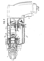
- FIG. 1 shows a rotary hammer in partial longitudinal section
- FIG. 2 shows a cross section along II-II in FIG. 1
- FIG. 3 shows a transmission development
- FIG. 4 shows a longitudinal section through an intermediate shaft of the rotary hammer in the position of use corresponding to FIG. 1 along IV-IV of FIGS. 3 and 4
- Figure 5 shows a second embodiment of an intermediate shaft according to Figure 3 in longitudinal section.
- FIG. 3 contains two partial cuts rotated about the axis of the intermediate shaft in the plane of the drawing.
- the viewing directions are designated III 'and III "in FIG. 3; the corresponding areas are numbered the same in FIG. 2.
- the hammer drill shown in Figure 1 of the drawing has a metal gear housing 1, which is arranged in an outer plastic shell 2. At its front end, the plastic shell merges into a cylindrical housing extension 3, which is designed, for example, for clamping additional devices - here a handle 4. At the front end of the housing extension 3, a tool holder 5 is arranged on the hammer drill, which is used to hold tools (not shown) - here a drill 6. At the rear end facing away from the tool holder 5. a pistol handle 7 is molded onto the plastic housing shell 2. In the pistol handle 7, a switch 8 with a pusher is installed, via which the hammer drill can be put into operation. At the lower end of the gun handle 7, a power supply cable 9 is inserted through an elastic grommet.
- the gear housing 1 essentially consists of a transverse wall 10, in which a bearing seat 11 is arranged approximately in the center for a front bearing of an armature shaft 13 of an electric motor which is designed as a ball bearing 12.
- the electric motor of which essentially only the front part of the armature shaft 13 is shown in the drawing, thus lies on the side of the transverse wall 10 of the transmission housing 1 facing away from the tool holder 5.
- the transverse wall 10 carries a tubular extension 14 on the side facing away from the electric motor , in which a cylindrical sleeve 16 for an air cushion hammer mechanism 15 is arranged.
- the extension 14 carries one at its front end facing the tool holder 5 Flange 17, which engages in a tubular fitting 18 in the interior of the housing shell 2, the gear housing 1 on its front.
- the gear housing 1 is supported on the other side with the transverse wall 10 on the inner surface of the housing shell 2.
- an O-ring 19 is inserted in an annular groove on the outer edge of the transverse wall 10 and touches the inner wall of the housing shell 2 with a slight prestress.
- the transverse wall 10 is supported on stops 20 formed by thickening the wall of the housing shell 2.
- the external spline toothing 25 is turned off in the area of the deep groove ball bearing 26, it is supported on the inner ring of the deep groove ball bearing 26 with the shoulder that arises.
- the outer ring of the deep groove ball bearing 26 is held in a correspondingly designed receptacle 26 'which is molded onto the transverse wall 10 (FIG. 3).
- the outer ring of the deep groove ball bearing 26 is supported on the base of the receptacle 26 'in such a way that from the intermediate shaft 24 transmitted axial forces can be introduced into the transverse wall 10.
- a bore 27 is coaxially made, in which a spring 28 is arranged.
- a shaft part 29 extends from the free end of the bore 27 and can be inserted telescopically against the force of the spring 28 into the bore 28.
- the free end of the shaft part 29 is in turn held in a needle bearing 30. With its string side, the shaft part 29 is held axially by the spring 28 against a plate 32 arranged in the base of a bearing seat 31 for the needle bearing 30.
- the bearing receptacle 31 is molded onto the housing shell 2, which may consist of a glass fiber reinforced plastic.
- a hub body 33 of a swash plate drive for the air cushion hammer mechanism 15 is rotatably arranged on the intermediate shaft 24.
- the hub body 33 On its outside, the hub body 33 has a single groove 34 for balls 35, which is closed in a ring-like manner and is inclined in one plane to the axis of the hub body 33.
- the hub body 33 is connected to the intermediate shaft 24 so that it can be disengaged by means of positive coupling elements.
- the outer spline teeth 25 of the intermediate shaft 24 serve as coupling elements, in which an annular inner spline teeth 36 engages in the bore of the hub body 33.
- an undercut 37 is located axially on the side facing the deep groove ball bearing 26 next to the internal spline toothing 36, the axial width of which is greater than the width of the annular internal spline toothing 36 of the hub body 33.
- the drive gear 23 On the end of the external spline toothing 25 facing the deep groove ball bearing 26, the drive gear 23 provided with a corresponding internal spline connection sits non-rotatably but axially displaceably on the intermediate shaft 24.
- a tooth height which is reduced in relation to the tooth height in the remaining partial region of the intermediate shaft 24.
- the transition 38 from the reduced to the undiminished tooth height forms an axial stop for the hub body 33 on its end face facing away from the drive gear 23.
- the bore in the hub body 33 is adapted at least in the region of the ring-shaped internal spline teeth 36 to the reduced tooth height of the external teeth 25 of the intermediate shaft 24.
- the hub body 33 is supported on the one hand with the annular internal spline 36 on the intermediate shaft 24.
- the hub body 33 is supported on an axially projecting collar 39 of the drive gear 23.
- the spring 28 In the position shown in FIG. 3, in which the coupling elements 25 (external spline teeth) of the intermediate shaft 24 are in engagement with the mating coupling elements 36 (internal spline teeth) of the hub body 33, the spring 28 ultimately braces the intermediate shaft with the axial stop (transition 38) against the hub body 33.
- This is in turn supported axially on the drive gear 23, which rests on the inner ring of the deep groove ball bearing 26.
- the external spline toothing 25 of the intermediate shaft 24 has the form of a toothing suitable for the transmission of rotary movements, in this case, for example, an involute toothing.
- a toothing suitable for the transmission of rotary movements in this case, for example, an involute toothing.
- the output pinion 40 of the intermediate shaft 24 can form the output pinion 40 of the intermediate shaft 24.
- This output pinion 40 meshes with a gear 41, which ultimately sets the tool held in the tool holder 5 - the drill 6 - in rotation.
- the hub body 33 In the position shown in FIG. 3, the hub body 33 is in the engaged position, in which it is set in rotation by the intermediate shaft 24.
- the intermediate shaft In order to interrupt the rotary connection between the intermediate shaft 24 and the hub body 33, that is to say ultimately to put the air cushion hammer mechanism 15 out of operation, the intermediate shaft must be moved forward in the direction of the tool holder 5.
- switching means that can be actuated from the outside have been arranged, which enable this disengagement of the striking mechanism.
- These switching means are designed as eccentrics 42 on a switching shaft 43.
- the selector shaft is guided in an associated bearing bore 44 which is formed in the transverse wall 10. In the operating position of the rotary hammer, the axis of the control shaft 43 and thus also the bearing bore 44 lie horizontally.
- the selector shaft 43 carries an actuating button 45 '(FIGS. 2 and 3).
- the switching eccentric 42 is designed in such a way that it does not touch the rear, spherical end 46 of the intermediate shaft 24 which projects from the deep groove ball bearing 26 in the position in which the striking mechanism is switched on. Only by turning the operating button 45 from the position shown in FIG. 3 by 180 ° does the outer surface of the control shaft 43 come into contact with the crowned end 46 of the intermediate shaft 24, so that it finally counteracts the force of the Spring 28 is moved forward.
- the switching eccentric 42 is thus loaded by the spring 28 in the axial direction only when the air cushion percussion mechanism is switched off, in which no stresses are placed on the machine.
- the switching eccentric 42 is completely relieved of the force of the spring 28.
- the spring force is fully available to eliminate the axial play of the hub body 33. In this way, minimal noise is achieved on the one hand.
- the elastic bracing of the hub body 33 against the housing of the hammer drill guarantees complete freedom from axial play - both due to manufacturing tolerances and the occurrence of wear.
- the groove 34 on the hub body 33 is assigned an outer groove 49 cut into the inside of a ring 48, between which the balls 35 are guided. To keep the balls at a defined distance, are they are guided in a cage 50 known from ball bearings.
- a wobble finger 51 which drives the air cushion hammer mechanism 15 of the rotary hammer back and forth, is integrally formed on the ring 48.
- the hammer mechanism of the hammer drill is arranged in the interior of the fixed bushing 16 which is attached in the extension 14. It consists of a cup piston 52 which is tightly and slidably guided in the liner 16 and in the cylindrical bore 53 of which a club 54 designed as a free-flying piston is also arranged in a tight and sliding manner.
- the rear end, facing away from the tool holder 5, of the pot piston 52 is fork-shaped and carries a pivot pin 55.
- a transverse bore is arranged in the center of the pivot pin 55, in which the wobble finger 51 engages with little movement play. As a result, the wobble finger 51 can move slightly in the axial direction in the transverse bore.
- an intermediate striker 56 extends into the front end region of the bore 53 facing away from the wobble finger 51.
- the intermediate striker is guided in an axially movable manner in a support sleeve 57.
- the intermediate striker touches with its front end in a manner known per se and therefore not shown in the drawing, the inner end of the drill 6 axially displaceable but non-rotatably held in the tool holder 5.
- the support sleeve 57 is in turn fastened inside a rotary sleeve 58 which is rotatably guided in the housing extension 3 in a manner not shown.
- the rear end of the rotary sleeve 58 is supported via an axial needle bearing 59 on the flange 17 of the extension 14 of the transverse wall 10.
- the rotary sleeve is in its radial direction rear, facing the needle bearing 59 on the protruding from the extension 15 end of the bushing 16.
- the gear 41 which meshes with the intermediate shaft 24, is rotatably guided on the cylindrical outer wall of the rotary sleeve 58.
- the body of the gearwheel 41 which has clutch claws on its end face on the engine, is held in engagement with associated clutch claws on the rear flange 62 of the rotary sleeve 58 via a compression spring 61 which is supported on a snap ring 60 which is inserted into an associated groove of the rotary sleeve 58 .
- the strength of the compression spring 61 is dimensioned such that the gear 41 is held in engagement with the rear flange of the rotary sleeve at normal drilling torques via the coupling claws.
- the rotary connection between the gear 41 and the rotary sleeve 58 is only interrupted when a response torque is reached.
- a rotary movement of the hub body 33 produces, as can be easily seen, a reciprocating movement of the pot piston 52.
- the racket is also moved in an axial direction via the air cushion which forms between the piston 52 and the racket 54 and acts as an energy store. and moving around.
- the striker 54 releases its energy, which finally acts as an axial stroke on the tool held in the tool holder 5.
- the tool - the drill 6 - is set in rotation via the above-described safety coupling consisting of gear 41 and rear flange 62 of the rotating sleeve 58.
- the striking mechanism By actuating the eccentric 42 arranged on the selector shaft 43, the striking mechanism can be put out of operation in the manner described above. Since the air cushion hammer mechanism is completely stationary in this case, an absolutely vibration-free run is achieved in impact stop mode, i.e. in drilling mode. It has been shown that the swash plate drive can be switched in any operating state of the rotary hammer.
- the second exemplary embodiment of an intermediate shaft 24 shown in FIG. 5 differs from the first exemplary embodiment in that the tooth height of the external spline toothing 25 is of the same height over the entire length of the intermediate shaft 24.
- the axial stop required for the axial displacement of the hub body 33 or for the axial bracing of the hub body 33 in the engaged state, which in the first embodiment is formed by the transition 38 from the reduced to the undiminished tooth height of the external spline toothing 25, is in this embodiment of at least one a recess of the intermediate shaft 24 inserted round ring 68 is formed.
- the recess consists of parts of an annular groove cut into each tooth of the external spline toothing 24. Of course, if the annular groove were cut deeper, the recess could extend into the core of the intermediate shaft 24.
Abstract
Es wird ein Bohrhammer mit einem Luftpolsterschlagwerk vorgeschlagen, welches von einem auskuppelbaren Taumelscheibenantrieb bewegbar ist. Der Taumelscheibenantrieb hat einen auf einer Zwischenwelle (24) angeordneten. in seiner Axialbewegung begrenzten Nabenkörper (33), dessen Kupplungselemente (36) bei Axialverschiebung wenigstens eines Teils der Zwischenwelle (24) mit an dieser angebrachten Kupplungselemente (25) außer formschlüssigen Eingriff kommen. Die Verschiebung der Zwischenwelle (24) geschieht durch von außen betätigbare Schaltmittel (42).A rotary hammer with an air cushion hammer mechanism is proposed, which can be moved by a swashplate drive that can be disengaged. The swash plate drive has one arranged on an intermediate shaft (24). in its axial movement limited hub body (33), the coupling elements (36) of axially displacing at least a part of the intermediate shaft (24) with coupling elements (25) attached to it come out of positive engagement. The intermediate shaft (24) is displaced by switching means (42) which can be actuated from the outside.
Description
Die Erfindung geht aus von einem Bohrhammer nach der Gattung des Hauptanspruchs (DE-OS 24 49 191, R. 2377). Es ist schon ein derartiger Bohrhammer bekannt geworden, bei dem das Schlagwerk automatisch in Betrieb gesetzt wurde, wenn das im Werkzeughalter des Bohrhammers gehaltene Werkzeug an das zu bearbeitende Werkstück angesetzt wurde. Dies geschieht durch eine Längsbewegung des Werkzeughalters, wobei eine das Schlagwerk in Bewegung setzende Kupplung betätigt wird. Um die Kupplung in ihrer Eingriffsstellung zu halten, muß der Bedienungsmann immer die Kraft einer Feder überwinden, die die Kupplung außer Eingriff zu bringen sucht. Ein reines Bohren ohne Axialbeaufschlagung des Werkzeugs ist mit dem bekannten Bohrhammer nicht möglich.The invention relates to a hammer drill according to the type of the main claim (DE-OS 24 49 191, R. 2377). Such a hammer drill has already become known, in which the striking mechanism was automatically started up when the tool held in the tool holder of the hammer drill was attached to the workpiece to be machined. This is done by a longitudinal movement of the tool holder, wherein a clutch that sets the striking mechanism in motion is actuated. To keep the clutch in its engaged position, the operator must always overcome the force of a spring that tries to disengage the clutch. Pure drilling without axial loading of the tool is not possible with the known hammer drill.
Der erfindungsgemäße Bohrhammer mit den kennzeichnenden Merkmalen des Hauptanspruchs hat demgegenüber den Vorteil, daß im - vom Bedienungsmann gewollt eingestellten - Schlagbohrbetrieb die Kupplung, über die der Taumelscheibenantrieb in Bewegung gesetzt wird, von einer Kupplung im Eingriff gehalten wird. Die Handhabbarkeit des Bohrhammers wird dadurch wesentlich erleichtert. Außerdem bietet dieser Bohrhammer die Möglichkeit als eine Bohrmaschine eingesetzt zu werden. Hierdurch wird die Möglichkeit eröffnet, eine leichte und deshalb für den Heimwerkerbetrieb geeignete Handbohrmaschine zu schaffen, bei der aber dennoch das bisher nur für relativ schwere Handwerkermaschinen vorbehaltene, höchst wirksame Luftpolsterschlagwerk eingesetzt werden kann.The hammer drill according to the invention with the characterizing features of the main claim has the advantage that in the - desired by the operator - percussion drilling the clutch over which the wobble disc drive is set in motion is held in engagement by a clutch. This significantly simplifies the handling of the rotary hammer. This hammer drill also offers the option of being used as a drilling machine. This opens up the possibility of creating a light hand drill, which is therefore suitable for home improvement, but which can still be used with the highly effective air cushion hammer mechanism that was previously reserved for relatively heavy handicraft machines.
Durch die in den Unteransprüchen aufgeführten Maßnahmen sind vorteilhafte Weiterbildungen und Verbesserungen des im Hauptanspruch angegebenen Bohrhammers möglich.Advantageous further developments and improvements of the hammer drill specified in the main claim are possible through the measures listed in the subclaims.
Ausführungsbeispiele der Erfindung sind in der Zeichnung dargestellt und in der nachfolgenden Beschreibung näher erläutert. Es zeigen Figur 1 einen Bohrhammer im Teillängsschnitt, Figur 2 einen Querschnitt längs II-II in der Figur 1, Figur 3 eine Getriebeabwicklung, Figur 4 einen Längsschnitt durch eine Zwischenwelle des Bohrhammers in der Figur 1 entsprechenden Gebrauchslage längs IV-IV der Figur 3 und Figur 5 ein zweites Ausführungsbeispiel einer Zwischenwelle gemäß Figur 3 im Längsschnitt.Embodiments of the invention are shown in the drawing and explained in more detail in the following description. FIG. 1 shows a rotary hammer in partial longitudinal section, FIG. 2 shows a cross section along II-II in FIG. 1, FIG. 3 shows a transmission development, FIG. 4 shows a longitudinal section through an intermediate shaft of the rotary hammer in the position of use corresponding to FIG. 1 along IV-IV of FIGS. 3 and 4 Figure 5 shows a second embodiment of an intermediate shaft according to Figure 3 in longitudinal section.
Die in Figur 3 dargestellte Getriebeabwicklung enthält zwei um die Achse der Zwischenwelle in die Zeichenebene gedrehte Teilschnitte. Die Blickrichtungen sind in Figur 3 mit III' und III" bezeichnet; die entsprechenden Bereiche sind in Figur 2 gleich beziffert.The transmission development shown in FIG. 3 contains two partial cuts rotated about the axis of the intermediate shaft in the plane of the drawing. The viewing directions are designated III 'and III "in FIG. 3; the corresponding areas are numbered the same in FIG. 2.
Beschreibung der AusführungsbeispieleDescription of the embodiments
Der in Figur 1 der Zeichnung dargestellte Bohrhämmer hat ein aus Metall bestehendes Getriebegehäuse 1, welches in einer äußeren Kunststoffschale 2 angeordnet ist. An ihrem vorderen Ende geht die Kunststoffschale in einen zylindrischen Gehäusefortsatz 3 über, der etwa zum Festspannen von Zusatzgeräten - hier ein Haltegriff 4 - ausgebildet ist. Am vorderen Ende des Gehäusefortsatzes 3 ist am Bohrhammer ein Werkzeughalter 5 angeordnet, der zur Aufnahme von nicht näher dargestellten Werkzeugen - hier ein Bohrer 6 - dient. Am hinteren, dem Werkzeughalter 5 abgewandten Ende ist . an die Kunststoff-Gehäuseschale 2 ein Pistolenhandgriff 7 angeformt. In den Pistolenhandgriff 7 ist ein mit einem Drücker 8 versehener Schalter eingebaut, über den der Bohrhammer in Betrieb gesetzt werden kann. Am unteren Ende des Pistolenhandgriffs 7 ist durch eine elastische Tülle ein Stromzuleitungskabel 9 eingeführt.The hammer drill shown in Figure 1 of the drawing has a
Das Getriebegehäuse 1 besteht im wesentlichen aus einer Querwand 10, in der etwa mittig ein Lagersitz 11 für ein vorderes, als Kugellager 12 ausgebildetes Lager einer Ankerwelle 13 eines Elektromotors angeordnet ist. Der Elektromotor, von dem in der Zeichnung im wesentlichen nur der vordere Teil der Ankerwelle 13 dargestellt ist, liegt also auf der vom Werkzeughalter 5 abgewandten Seite der Querwand 10 des Getriebegehäuses 1. Auf der dem Elektromotor abgewandten Seite trägt die Querwand 10 einen rohrförmigen Fortsatz 14, in dem eine zylindrische Laufbuchse 16 für ein Luftpolsterschlagwerk 15 angeordnet ist. An ihrem vorderen, dem Werkzeughalter 5 zugewandten Ende trägt der Fortsatz 14 einen Flansch 17, der in einem rohrförmigen Einpaß 18 im Innern der Gehäuseschale 2 eingreifend das Getriebegehäuse 1 an seiner Vorderseite abstützt. Wie aus Figur 1 erkenntlich ist, stützt sich das Getriebegehäuse 1 auf der anderen Seite mit der Querwand 10 an der Innenfläche der Gehäuseschale 2 ab. Dazu ist an dem äußeren Rand der Querwand 10 in einer Ringnut ein 0-Ring 19 eingelegt, der die Innenwand der Gehäuseschale 2 mit leichter Vorspannung berührt. In Achsrichtung stützt sich die Querwand 10 an durch Verdikkungen der Wandung der Gehäuseschale 2 gebildeten Anschlägen 20 ab.The
In Figur 2 der Zeichnung ist zu sehen, daß der Fortsatz 14 und der Lagersitz 11, in welchem konzentrisch die Ankerwelle 13 geführt ist, in der Längsmittelebene 21 des Hammers angeordnet sind. Das im Kugellager 12 gelagerte Ende der Ankerwelle 13 trägt ein Motorritzel 22. Das Motorritzel 22 kämmt wiederum mit einem Zahnrad 23, welches drehfest auf einer Zwischenwelle 24 sitzt. Die Zwischenwelle 24, die seitlich versetzt zur Längsmittelebene 21 angeordnet ist, trägt über ihre ganze Länge eine Außenkeilwellenverzahnung 25 und ist mit ihrem der Querwand 10 zugewandten Ende in einem Rillenkugellager 26 gehalten. Sie stützt sich, da die Außenkeilwellenverzahnung 25 in dem Bereich des Rillenkugellagers 26 abgedreht ist, mit der entstehenden Schulter am Innenring des Rillenkugellagers 26 ab. Der Außenring des Rillenkugellagers 26 ist in einer entsprechend ausgebildeten Aufnahme 26', welche an die Querwand 10 angeformt ist, gehalten (Figur 3). Dabei stützt sich der Außenring des Rillenkugellagers 26 derart am Grunde der Aufnahme 26' ab, daß von der Zwischenwelle 24 übertragene Axialkräfte in die Querwand 10 eingeleitet werden können. In das vom Rillenkugellager 26 abgewandte Ende der Zwischenwelle 24 ist koaxial eine Bohrung 27 eingebracht, in der eine Feder 28 angeordnet ist. Aus dem freien Ende der Bohrung 27 erstreckt sich das vordere Ende eines Wellenteils 29, welches teleskopartig gegen die Kraft der Feder 28 in die Bohrung 28 einschiebbar ist. Das freie Ende des Wellenteils 29 wiederum ist in einen Nadellager 30 gehalten. Mit seiner Strinseite wird das Wellenteil 29 von der Feder 28 axial gegen einen im Grund einer Lageraufnahme 31 für das Nadellager 30 angeordneten Platte 32 gehalten. Die Lageraufnahme 31 ist an die Gehäuseschale 2, die etwa aus einem glasfaserverstärkten Kunststoff bestehen kann, angeformt.In Figure 2 of the drawing it can be seen that the
Auf der Zwischenwelle 24 ist drehbar ein Nabenkörper 33 eines Taumelscheibenantriebs für das Luftpolsterschlagwerk 15 angeordnet. An seiner Außenseite weist der Nabenkörper 33 eine einzige, in sich ringförmig geschlossene, zur Achse des Nabenkörpers 33 in einer Ebene schief liegende Laufrille 34 für Kugeln 35 auf. Der Nabenkörper 33 ist mittels formschlüssiger Kupplungslemente auskuppelbar mit der Zwischenwelle 24 verbunden. Als Kupplungselemente dient einerseits die Außenkeilwellenverzahnung 25 der Zwischenwelle 24, in welche eine ringförmige Innenkeilwellenverzahnung 36 in der Bohrung des Nabenkörpers 33 eingreift. Im eingekuppelten, in Figur 3 dargestellten Zustand liegt axial auf der dem Rillenkugellager 26 zugewandten Seite neben der Innenkeilwellenverzahnung 36 ein Freistich 37, dessen axiale Breite größer ist als die Breite der ringförmigen Innenkeilwellenverzahnung 36 des Nabenkörpers 33.A
Auf dem dem Rillenkugellager 26 zugewandten Ende der Außenkeilwellenverzahnung 25 sitzt das mit einer entsprechenden Innenkeilwellenverbindung versehene Antriebszahnrad 23 drehfest aber axial verschieblich auf der Zwischenwelle 24. Wie Figur 3 und Figur 4 der Zeichnung erkennen lassen, haben die Zähne der Außenkeilwellenverzahnung 25 in dem Bereich, in dem auf der Zwischenwelle 24 der Nabenkörper 33 und das Antriebszahnrad 23 angeordnet sind, eine gegenüber der Zahnhöhe im restlichen Teilbereich der Zwischenwelle 24 verminderte Zahnhöhe. Der Übergang 38 von der verminderten auf die unverminderte Zahnhöhe bildet einen Axialanschlag für den Nabenkörper 33 an dessen dem Antriebszahnrad 23 abgewandten Stirnseite. Natürlich ist die Bohrung im Nabenkörper 33 zumindest in dem Bereich der ringförmigen Innenkeilwellenverzahnung 36 der verminderten Zahnhöhe der Außenverzahnung 25 der Zwischenwelle 24 angepaßt. Damit stützt sich der Nabenkörper 33 einerseits mit der ringförmigen Innenkeilwellenverzahnung 36 auf der Zwischenwelle 24 ab. Auf der anderen Seite stützt sich der Nabenkörper 33 auf einem axial vorstehenden Bund 39 des Antriebszahnrades 23 ab. In der in Figur 3 dargestellten Stellung, in der die Kupplungselemente 25 (Aussenkeilwellenverzahnung) der Zwischenwelle 24 mit den Gegenkupplungselementen 36 (Innenkeilwellenverzahnung) des Nabenkörpers 33 im Eingriff sind, verspannt letztlich die Feder 28 die Zwischenwelle mit dem Axialanschlag (Übergang 38) gegen den Nabenkörper 33. Dieser stützt sich axial wiederum am Antriebszahnrad 23 ab, welche am Innenring des Rillenkugellagers 26 anliegt.On the end of the external spline toothing 25 facing the deep groove ball bearing 26, the
Die Außenkeilwellenverzahnung 25 der Zwischenwelle 24 hat die Form einer zur Übertragung von Drehbewegungen geeigneten Verzahnung, hier etwa einer Evolventenverzahnung. Deshalb kann der vordere dem Rillenkugellager 26 abgewandte Teil der Keilwellenverzahnung, der die unverminderte Zahnhöhe aufweist, das Abtriebsritzel 40 der Zwischenwelle 24 bilden. Dieses Abtriebsritzel 40 kämmt mit einem Zahnrad 41, welches letztlich das im Werkzeughalter 5 gehaltene Werkzeug - den Bohrer 6 - in Drehung versetzt.The external spline toothing 25 of the intermediate shaft 24 has the form of a toothing suitable for the transmission of rotary movements, in this case, for example, an involute toothing. Of half the front part of the spline toothing facing away from the deep groove ball bearing 26 and having the undiminished tooth height can form the output pinion 40 of the intermediate shaft 24. This output pinion 40 meshes with a gear 41, which ultimately sets the tool held in the tool holder 5 - the drill 6 - in rotation.
In der in Figur 3 dargestellten Stellung befindet sich der Nabenkörper 33 in der eingekuppelten Stellung, in der er von der Zwischenwelle 24 in Drehung versetzt wird. Um nun die Drehverbindung zwischen der Zwischenwelle 24 und dem Nabenkörper 33 zu unterbrechen, d.h. letztlich das Luftpolsterschlagwerk 15 außer Betrieb zusetzen, muß die Zwischenwelle nach vorn in Richtung auf den Werkzeughalter 5 verschoben werden. Dazu sind von außen betätigbare Schaltmittel angeordnet worden, die dieses Auskuppeln des Schlagwerks ermöglichen. Diese Schaltmittel sind als Exzenter 42 an einer Schaltwelle 43 ausgestaltet. Die Schaltwelle ist in einer zugeordneten Lagerbohrung 44 geführt, welche in die Querwand 10 eingeformt ist. In der Betriebsstellung des Bohrhammers liegt die Achse der Schaltwelle 43 und damit auch der Lagerbohrung 44 waagerecht. An ihrem äusseren, aus dem Gehäuse des Bohrhammers hervorragenden Ende trägt die Schaltwelle 43 einen Betätigungsknopf 45' (Figur 2 und 3). Wie Figur 3 zeigt, ist der Schaltexzenter 42 derart ausgestaltet, daß er das hintere, aus dem Rillenkugellager 26 hervorragende, ballig ausgeführte Ende 46 der Zwischenwelle 24 in der Stellung, in der das Schlagwerk eingeschaltet ist, nicht berührt. Erst durch Drehung des Betätigungsknopfes 45 aus der in Figur 3 dargestellten Stellung um 180° kommt die Außenfläche der Schaltwelle 43 mit dem balligen Ende 46 der Zwischenwelle 24 in Berührung, so daß sie schließlich entgegen der Kraft der Feder 28 nach vorn verschoben wird. Dabei wird die oben erwähnte axiale Verspannung des Nabenkörpers 33 über das Zahnrad 23 letztlich gegen das Gehäuse des Bohrhammers aufgehoben. Bei der Vorwärtsbewegung der Zwischenwelle 24 kommt die vordere Stirnseite des Nabenkörpers 33 mit einem von einem Teil des Maschinengehäuses gebildeten Anschlag 47 in Berührung, wodurch sie in ihrer Axialbewegung begrenzt ist. Hierdurch wird schließlich die Innenkeilwellenverzahnung 36 des Nabenkörpers 33 aus der Aussenkeilwellenverzahnung 25 der Zwischenwelle 24 ausgerückt und in den Freistich 37 verschoben: Die Drehverbindung zwischen der Zwischenwelle und dem Nabenkörper 33 des Taumelscheibenantriebs ist damit unterbrochen worden. Die sich weiter drehende Zwischenwelle versetzt aber das Zahnrad 41 weiterhin in Drehung, so daß reiner Bohrbetrieb mit dem Bohrhammer möglich ist. Der Schaltexzenter 42 ist also nur bei abgeschalteten Luftpolsterschlagwerk, bei dem von ihm keine Beanspruchungen der Maschine ausgehen, von der Feder 28 in Axialrichtung belastet. Bei eingeschaltetem Schlagwerk ist der Schaltexzenter 42 von der Kraft der Feder 28 vollkommen entlastet. Die Federkraft steht voll zur Elimination des Axialspiels des Nabenkörpers 33 zur Verfügung. Auf diese Weise wird einerseits eine minimale Geräuschentwicklung erzielt. Andererseits wird durch die elastische Verspannung des Nabenkörpers 33 gegen das Gehäuse des Bohrhammers vollkommene Axialspielfreiheit - sowohl durch Fertigungstoleranzen als auch Auftreten von Verschleiß - garantiert.In the position shown in FIG. 3, the
Der Laufrille 34 am Nabenkörper 33 ist eine an der Innenseite eines Rings 48 eingeschnittene Außenlaufrille 49 zugeordnet, zwischen denen die Kugeln 35 geführt sind. Um die Kugeln in einem definierten Abstand zu halten, sind sie in einem von Kugellagern her bekannten Käfig 50 geführt. Einstückig ist am Ring 48 ein Taumelfinger 51 angeformt, der das Luftpolsterschlagwerk 15 des Bohrhammers hin- und hergehend antreibt.The groove 34 on the
Das Schlagwerk des Bohrhammers ist im Innern der feststehenden, im Fortsatz 14 angebrachten Laufbuchse 16 angeordnet. Es besteht aus einem in der Laufbuchse 16 dicht und gleitend geführten Topfkolben 52, in dessen zylindrischer Bohrung 53 ebenfalls dicht und gleitend ein als frei fliegender Kolben ausgebildeter Schläger 54 angeordnet ist. Das hintere, dem Werkzeughalter 5 abgewandte Ende des Topfkolbens'52 ist gabelartig ausgebildet und trägt einen Drehbolzen 55. Mittig ist im Drehbolzen 55 eine Querbohrung angeordnet, in die der Taumelfinger 51 mit geringem Bewegungsspiel eingreift. Dadurch kann sich der Taumelfinger 51 leicht in axialer Richtung in der Querbohrung bewegen. In den vorderen, dem Taumelfinger 51 abgewandten Endbereich der Bohrung 53 erstreckt sich das innere Ende eines Zwischendöppers 56. Der Zwischendöpper ist axial beweglich in einer Abstützhülse 57 geführt. Der Zwischendöpper berührt mit seinem vorderen Ende in an sich bekannter und deshalb in der Zeichnung nicht näher dargestellter Art und Weise das innere Ende des im Werkzeughalter 5 axial verschiebbar, aber drehfest gehaltenen Bohrers 6.The hammer mechanism of the hammer drill is arranged in the interior of the fixed
Die Abstützhülse 57 wiederum ist im Innern einer Drehhülse 58 befestigt, die in nicht näher dargestellter Art und Weise drehbar im Gehäusefortsatz 3 geführt ist. Das hintere Ende der Drehhülse 58 stützt sich über ein Axialnadellager 59 am Flansch 17 des Fortsatzes 14 der Querwand 10. In radialer Richtung ist die Drehhülse in ihrem hinteren, dem Nadellager 59 zugewandten Bereich auf dem aus dem Fortsatz 15 hervorstehenden Ende der Laufbuchse 16 geführt. Auf der zylindrischen Außenwand der Drehhülse 58 ist drehbar das Zahnrad 41, welches mit der Zwischenwelle 24 kämmt, geführt. Über eine an einem Sprengring 60, der in eine zugeordnete Nut der Drehhülse 58 eingesetzt ist, sich abstützende Druckfeder 61 wird der Körper des Zahnrades 41, der an seiner motorseitigen Stirnfläche Kupplungsklauen trägt, mit zugeordneten Kupplungsklauen am hinteren Flansch 62 der Drehhülse 58 in Eingriff gehalten. Die Stärke der Druckfeder 61 ist dabei so bemessen, daß das Zahnrad 41 bei normalen Bohrmomenten über die Kupplungsklauen mit dem hinteren Flansch der Drehhülse in Eingriff gehalten wird. Erst bei Erreichen eines Ansprechmoments wird die Drehverbindung zwischen dem Zahnrad 41 und der Drehhülse 58 unterbrochen.The
Eine Drehbewegung des Nabenkörpers 33 erzeugt, wie leicht einzusehen ist, eine hin- und hergehende Bewegung des Topfkolbens 52. Über das sich zwischen dem Kolben 52 und dem Schläger 54 bildende Luftpolster, welches als Energiespeicher wirkt, wird der Schläger ebenfalls in eine axiale Hin- und Herbewegung versetzt. Beim Auftreffen auf das innere Ende des Zwischendöppers 56 gibt der Schläger 54 seine Energie ab, welche schließlich am im Werkzeughalter 5 gehaltenen Werkzeug als Axialschlag wirksam wird. Dabei wird über die oben beschriebene, aus Zahnrad 41 und hinterem Flansch 62 der Drehhülse 58 bestehende Sicherheitskupplung das Werkzeug - der Bohrer 6 - in Drehung versetzt.A rotary movement of the
Durch Betätigung des an der Schaltwelle 43 angeordneten Exzenters 42 kann in oben beschriebener Art und Weise das Schlagwerk außer Betrieb gesetzt werden. Da das Luftpolsterschlagwerk in diesem Falle vollkommen still steht, wird ein absolut vibrationsfreier Lauf im Schlagstopbetrieb, also im Bohrbetrieb, erzielt. Es hat sich gezeigt, daß der Taumelscheibenantrieb in jedem Betriebszustand des Bohrhammers geschaltet werden kann.By actuating the eccentric 42 arranged on the
Das in Figur 5 dargestellte zweite Ausführungsbeispiel einer Zwischenwelle 24 unterscheidet sich vom ersten Ausführungsbeispiel dadurch, daß die Zahnhöhe der Aussenkeilwellenverzahnung 25 über die ganze Länge der Zwischenwelle 24 gleich hoch ist. Der für das axiale Verschieben des Nabenkörpers 33 bzw. für die axiale Verspannung des Nabenkörpers 33 im eingekuppelten Zustand erforderliche Axialanschlag, der beim ersten Ausführungsbeispiel vom Übergang 38 von der verminderten zur unverminderten Zahnhöhe der Außenkeilwellenverzahnung 25 gebildet ist, ist bei diesem Ausführungsbeispiel von einem in mindestens eine Ausnehmung der Zwischenwelle 24 eingelegten Rundring 68 gebildet. Bei dem dargestellten Ausführungsbeispiel besteht die Ausnehmung aus in jedem Zahn der Außenkeilwellenverzahnung 24 eingeschnittenen Teilen einer Ringnut. Natürlich könnte sich, wenn die Ringnut tiefer eingeschnitten wäre, die Ausnehmung bis in den Kern der Zwischenwelle 24 hineinerstrecken.The second exemplary embodiment of an intermediate shaft 24 shown in FIG. 5 differs from the first exemplary embodiment in that the tooth height of the
Die Funktion dieses zweiten Ausführungsbeispieles der Zwischenwelle 24 ist sinngemäß die gleich wie die erste Ausführungsform.The function of this second embodiment of the intermediate shaft 24 is basically the same as the first embodiment.
Claims (15)
Applications Claiming Priority (2)
| Application Number | Priority Date | Filing Date | Title |
|---|---|---|---|
| DE19803039669 DE3039669A1 (en) | 1980-10-21 | 1980-10-21 | DRILLING HAMMER |
| DE3039669 | 1980-10-21 |
Publications (3)
| Publication Number | Publication Date |
|---|---|
| EP0050192A1 true EP0050192A1 (en) | 1982-04-28 |
| EP0050192B1 EP0050192B1 (en) | 1984-02-22 |
| EP0050192B2 EP0050192B2 (en) | 1989-10-04 |
Family
ID=6114858
Family Applications (1)
| Application Number | Title | Priority Date | Filing Date |
|---|---|---|---|
| EP81105591A Expired EP0050192B2 (en) | 1980-10-21 | 1981-07-16 | Drill hammer |
Country Status (4)
| Country | Link |
|---|---|
| US (1) | US4446931A (en) |
| EP (1) | EP0050192B2 (en) |
| JP (1) | JPS57102779A (en) |
| DE (2) | DE3039669A1 (en) |
Cited By (3)
| Publication number | Priority date | Publication date | Assignee | Title |
|---|---|---|---|---|
| EP0135654A1 (en) * | 1983-09-29 | 1985-04-03 | Licentia Patent-Verwaltungs-GmbH | Guide of the piston of a hand-held air cushion percussion drill |
| WO1989011955A1 (en) * | 1988-06-04 | 1989-12-14 | Robert Bosch Gmbh | Drilling hammer |
| EP2767367A4 (en) * | 2012-12-11 | 2015-10-14 | Zhejiang Benyu Tools Co Ltd | Transmission switching device of electric hammer |
Families Citing this family (39)
| Publication number | Priority date | Publication date | Assignee | Title |
|---|---|---|---|---|
| DE3319934A1 (en) * | 1982-06-02 | 1983-12-15 | Black & Decker, Inc. (eine Gesellschaft n.d.Ges.d. Staates Delaware), 19711 Newark, Del. | Percussion drilling machine |
| JPS5930607A (en) * | 1982-08-12 | 1984-02-18 | Hitachi Koki Co Ltd | Electric hammer drill |
| DE3322964A1 (en) * | 1983-06-25 | 1985-01-24 | Eugen Lutz GmbH u. Co Maschinenfabrik, 7130 Mühlacker | IMPACT TOOL, ESPECIALLY DRILLING HAMMER |
| DE3429140A1 (en) * | 1984-08-08 | 1986-02-20 | Black & Decker Inc., Newark, Del. | DRILLING HAMMER WITH A PNEUMATIC STRIKE |
| DE3504650C2 (en) * | 1985-02-12 | 1994-01-20 | Bosch Gmbh Robert | Hammer drill with increased actuation force for the coupling of the impact drive |
| DE3627869A1 (en) * | 1986-08-16 | 1988-02-18 | Bosch Gmbh Robert | DRIVE SHUTDOWN |
| NL8801466A (en) * | 1988-06-07 | 1990-01-02 | Emerson Electric Co | DEVICE FOR DRIVING A DRILL AND / OR IMPACT TOOL. |
| USRE35372E (en) * | 1988-06-07 | 1996-11-05 | S-B Power Tool Company | Apparatus for driving a drilling or percussion tool |
| DE4013512A1 (en) * | 1990-04-27 | 1991-10-31 | Black & Decker Inc | SWITCHING DEVICE FOR SWITCHING A POWERED TOOL |
| US5447205A (en) * | 1993-12-27 | 1995-09-05 | Ryobi Motor Products | Drill adjustment mechanism for a hammer drill |
| US5588496A (en) * | 1994-07-14 | 1996-12-31 | Milwaukee Electric Tool Corporation | Slip clutch arrangement for power tool |
| DE19540391A1 (en) * | 1995-10-30 | 1997-05-07 | Hilti Ag | Drilling and chiseling device |
| DE19955412A1 (en) * | 1999-11-18 | 2001-05-23 | Hilti Ag | Drilling and chiseling device |
| DE10213093B4 (en) * | 2002-03-23 | 2013-06-20 | Andreas Stihl Ag & Co. | Hand drill with a combustion engine |
| GB2394437A (en) * | 2002-10-23 | 2004-04-28 | Black & Decker Inc | Hammer including a piston with wear-reducing washers |
| GB2394517A (en) * | 2002-10-23 | 2004-04-28 | Black & Decker Inc | Powered hammer having a spindle lock with synchronising element |
| JP3976187B2 (en) * | 2002-11-20 | 2007-09-12 | 株式会社マキタ | Hammer drill |
| DE602004026665D1 (en) * | 2003-08-06 | 2010-06-02 | Hitachi Koki Kk | percussion drill |
| DE102004012820B3 (en) * | 2004-03-16 | 2005-11-17 | Wacker Construction Equipment Ag | Wobble drive |
| DE102004025951A1 (en) * | 2004-05-27 | 2005-12-22 | Robert Bosch Gmbh | Hand tool, in particular drill and / or percussion hammer |
| DE102004026845A1 (en) * | 2004-06-02 | 2005-12-22 | Robert Bosch Gmbh | Hand tool, in particular drill and / or percussion hammer |
| DE102004034268B3 (en) * | 2004-07-15 | 2005-12-29 | Wacker Construction Equipment Ag | Rotary hammer with safety coupling |
| DE102004058686A1 (en) * | 2004-09-03 | 2006-03-09 | Robert Bosch Gmbh | Power tool with a drive that can be switched over between the operating modes drilling, impact drilling, and chiseling |
| DE102004044499B4 (en) * | 2004-09-15 | 2021-02-18 | Robert Bosch Gmbh | Hand machine tool, in particular drill and / or percussion hammer |
| DE102005019196A1 (en) * | 2005-04-25 | 2006-10-26 | Hilti Ag | Hand tool used a drill comprises a wobble device having a drive element rotating about a drive axle and a driven element coupled with the drive element via a wobble bearing |
| DE102005041448A1 (en) | 2005-08-31 | 2007-03-01 | Robert Bosch Gmbh | Hammer drill, comprises manually operated switch with outer shell and sealing ring |
| DE102005041447A1 (en) * | 2005-08-31 | 2007-03-01 | Robert Bosch Gmbh | Hammer drill, comprises intermediate shaft designed as plain cylindrical element holding driving wheel, driven wheel, and slide bearing |
| DE102005047353A1 (en) * | 2005-10-04 | 2007-04-05 | Robert Bosch Gmbh | Electric-powered machine tool e.g. hand-operated power drill, for use in pistol construction, has flange to drive train and divided into drive end and gear end bearing bracket units connected with each other by vibration damping unit |
| DE102005047600A1 (en) * | 2005-10-05 | 2007-04-12 | Robert Bosch Gmbh | Hand tool with a shaft and a mounted on the shaft Hubantriebslager |
| JP4981506B2 (en) * | 2007-04-12 | 2012-07-25 | 株式会社マキタ | Hammer drill |
| US7806201B2 (en) * | 2007-07-24 | 2010-10-05 | Makita Corporation | Power tool with dynamic vibration damping |
| CA2723384C (en) * | 2008-05-07 | 2016-09-20 | Milwaukee Electric Tool Corporation | Drive assembly for a power tool |
| US20110194796A1 (en) * | 2010-02-05 | 2011-08-11 | Schaeffler Technologies Gmbh & Co. Kg | Angled Bore Bearing |
| US8636081B2 (en) | 2011-12-15 | 2014-01-28 | Milwaukee Electric Tool Corporation | Rotary hammer |
| JP5512441B2 (en) * | 2010-07-22 | 2014-06-04 | 株式会社マキタ | Screw tightening tool |
| US9630307B2 (en) | 2012-08-22 | 2017-04-25 | Milwaukee Electric Tool Corporation | Rotary hammer |
| US20150367490A1 (en) * | 2013-03-26 | 2015-12-24 | Hitachi Koki Co., Ltd. | Power tool |
| JP6325360B2 (en) * | 2014-06-12 | 2018-05-16 | 株式会社マキタ | Impact tool |
| JP6479570B2 (en) * | 2015-05-19 | 2019-03-06 | 株式会社マキタ | Work tools |
Citations (4)
| Publication number | Priority date | Publication date | Assignee | Title |
|---|---|---|---|---|
| DE1948055A1 (en) * | 1969-09-23 | 1971-04-01 | Impex Essen Vertrieb | Electrically operated rotary hammer |
| DE2242944A1 (en) * | 1972-08-31 | 1974-03-14 | Bosch Gmbh Robert | DRILL |
| DE1938660B2 (en) * | 1969-07-30 | 1974-10-03 | Metabowerke Kg, Closs, Rauch & Schnizler, 7440 Nuertingen | Hammer drill |
| DE2449191A1 (en) * | 1974-10-16 | 1976-05-06 | Bosch Gmbh Robert | CRAFT MACHINE |
Family Cites Families (6)
| Publication number | Priority date | Publication date | Assignee | Title |
|---|---|---|---|---|
| US2385439A (en) * | 1943-08-27 | 1945-09-25 | Gubbins Charles Henry | Mechanical hammer |
| US2824455A (en) * | 1952-06-27 | 1958-02-25 | Milwaukee Electric Tool Corp | Portable reciprocating saw |
| US3399441A (en) * | 1965-12-13 | 1968-09-03 | Imamura Yukio | High speed recoilless chisel device |
| BE793096A (en) * | 1971-12-23 | 1973-06-20 | Caterpillar Tractor Co | PARKING BRAKE ARRANGEMENT WITH HYDROSTATIC FINAL DRIVE DEVICE DECOUPLING FOR A LOADER |
| US4158970A (en) * | 1977-06-15 | 1979-06-26 | Black & Decker Inc. | Override arrangement and actuating knob for a shifting mechanism in portable tools |
| DE2820128A1 (en) * | 1978-05-09 | 1979-11-22 | Bosch Gmbh Robert | CRAFT MACHINE |
-
1980
- 1980-10-21 DE DE19803039669 patent/DE3039669A1/en not_active Ceased
-
1981
- 1981-07-16 DE DE8181105591T patent/DE3162371D1/en not_active Expired
- 1981-07-16 EP EP81105591A patent/EP0050192B2/en not_active Expired
- 1981-09-14 US US06/302,112 patent/US4446931A/en not_active Expired - Lifetime
- 1981-10-21 JP JP56167310A patent/JPS57102779A/en active Granted
Patent Citations (4)
| Publication number | Priority date | Publication date | Assignee | Title |
|---|---|---|---|---|
| DE1938660B2 (en) * | 1969-07-30 | 1974-10-03 | Metabowerke Kg, Closs, Rauch & Schnizler, 7440 Nuertingen | Hammer drill |
| DE1948055A1 (en) * | 1969-09-23 | 1971-04-01 | Impex Essen Vertrieb | Electrically operated rotary hammer |
| DE2242944A1 (en) * | 1972-08-31 | 1974-03-14 | Bosch Gmbh Robert | DRILL |
| DE2449191A1 (en) * | 1974-10-16 | 1976-05-06 | Bosch Gmbh Robert | CRAFT MACHINE |
Cited By (3)
| Publication number | Priority date | Publication date | Assignee | Title |
|---|---|---|---|---|
| EP0135654A1 (en) * | 1983-09-29 | 1985-04-03 | Licentia Patent-Verwaltungs-GmbH | Guide of the piston of a hand-held air cushion percussion drill |
| WO1989011955A1 (en) * | 1988-06-04 | 1989-12-14 | Robert Bosch Gmbh | Drilling hammer |
| EP2767367A4 (en) * | 2012-12-11 | 2015-10-14 | Zhejiang Benyu Tools Co Ltd | Transmission switching device of electric hammer |
Also Published As
| Publication number | Publication date |
|---|---|
| EP0050192B2 (en) | 1989-10-04 |
| JPS57102779A (en) | 1982-06-25 |
| DE3162371D1 (en) | 1984-03-29 |
| EP0050192B1 (en) | 1984-02-22 |
| JPS6351828B2 (en) | 1988-10-17 |
| US4446931A (en) | 1984-05-08 |
| DE3039669A1 (en) | 1982-05-27 |
Similar Documents
| Publication | Publication Date | Title |
|---|---|---|
| EP0050192B1 (en) | Drill hammer | |
| DE3205141C2 (en) | ||
| DE4236819C2 (en) | Motorized turning tool device | |
| DE19801986B4 (en) | Device for switching operating modes for a hammer drill | |
| DE19944294B4 (en) | Power driven rotary hammer with improved operating mode switch | |
| DE3504650C2 (en) | Hammer drill with increased actuation force for the coupling of the impact drive | |
| DE19545260A1 (en) | Hammer drill | |
| DE102005033672B4 (en) | Electric hammer drill | |
| WO1990001400A1 (en) | Hammer drill or concrete breaker | |
| DE3224176C2 (en) | Motor-driven striking hand machine tool | |
| DE3807078A1 (en) | DRILLING HAMMER | |
| EP0023951B1 (en) | Motor driven hand tool, especially combination tool for home-workers | |
| DE3235544C2 (en) | ||
| EP0463416B1 (en) | Electrical hammerdrill | |
| WO2010072433A1 (en) | Hand-held machine tool | |
| DE4302083A1 (en) | Power tool, in particular power tool | |
| EP0884138A2 (en) | Hammer drill | |
| DE3039631A1 (en) | DRILLING HAMMER | |
| EP0318480B1 (en) | Device for switching off percussion tools | |
| DE3807308A1 (en) | Radially acting safety friction clutch of a power tool | |
| WO1989011955A1 (en) | Drilling hammer | |
| EP3456479B1 (en) | Drive train assembly for a powered machine tool | |
| DE102004052329A1 (en) | Synchronization and switching unit for one-button selector switch and power tool with synchronization and switching unit | |
| DE3213672C2 (en) | Actuator for switching a hammer drill with a pneumatic hammer mechanism that can be actuated by a swash plate drive from the "drilling" operating state to the "hammer drilling" operating state | |
| DE3136264A1 (en) | Electro-pneumatic hammer drill |
Legal Events
| Date | Code | Title | Description |
|---|---|---|---|
| PUAI | Public reference made under article 153(3) epc to a published international application that has entered the european phase |
Free format text: ORIGINAL CODE: 0009012 |
|
| 17P | Request for examination filed |
Effective date: 19810716 |
|
| AK | Designated contracting states |
Designated state(s): CH DE GB NL |
|
| GRAA | (expected) grant |
Free format text: ORIGINAL CODE: 0009210 |
|
| AK | Designated contracting states |
Designated state(s): CH DE GB LI NL |
|
| REF | Corresponds to: |
Ref document number: 3162371 Country of ref document: DE Date of ref document: 19840329 |
|
| PLBI | Opposition filed |
Free format text: ORIGINAL CODE: 0009260 |
|
| 26 | Opposition filed |
Opponent name: BLACK & DECKER INC. Effective date: 19841122 |
|
| NLR1 | Nl: opposition has been filed with the epo |
Opponent name: BLACK & DECKER INC. |
|
| PGFP | Annual fee paid to national office [announced via postgrant information from national office to epo] |
Ref country code: NL Payment date: 19860731 Year of fee payment: 6 |
|
| PG25 | Lapsed in a contracting state [announced via postgrant information from national office to epo] |
Ref country code: NL Effective date: 19880201 |
|
| NLV4 | Nl: lapsed or anulled due to non-payment of the annual fee | ||
| PUAH | Patent maintained in amended form |
Free format text: ORIGINAL CODE: 0009272 |
|
| STAA | Information on the status of an ep patent application or granted ep patent |
Free format text: STATUS: PATENT MAINTAINED AS AMENDED |
|
| 27A | Patent maintained in amended form |
Effective date: 19891004 |
|
| AK | Designated contracting states |
Kind code of ref document: B2 Designated state(s): CH DE GB NL |
|
| REG | Reference to a national code |
Ref country code: GB Ref legal event code: 746 Effective date: 19960731 |
|
| PGFP | Annual fee paid to national office [announced via postgrant information from national office to epo] |
Ref country code: GB Payment date: 20000627 Year of fee payment: 20 |
|
| PGFP | Annual fee paid to national office [announced via postgrant information from national office to epo] |
Ref country code: CH Payment date: 20000721 Year of fee payment: 20 |
|
| PGFP | Annual fee paid to national office [announced via postgrant information from national office to epo] |
Ref country code: DE Payment date: 20010420 Year of fee payment: 20 |
|
| PG25 | Lapsed in a contracting state [announced via postgrant information from national office to epo] |
Ref country code: LI Free format text: LAPSE BECAUSE OF EXPIRATION OF PROTECTION Effective date: 20010715 Ref country code: GB Free format text: LAPSE BECAUSE OF EXPIRATION OF PROTECTION Effective date: 20010715 Ref country code: CH Free format text: LAPSE BECAUSE OF EXPIRATION OF PROTECTION Effective date: 20010715 |
|
| REG | Reference to a national code |
Ref country code: GB Ref legal event code: PE20 Effective date: 20010715 |
|
| REG | Reference to a national code |
Ref country code: CH Ref legal event code: PL |