EP0048485A2 - Method and apparatus for exposing contents of an opened envelope with gravity assist - Google Patents
Method and apparatus for exposing contents of an opened envelope with gravity assist Download PDFInfo
- Publication number
- EP0048485A2 EP0048485A2 EP81107506A EP81107506A EP0048485A2 EP 0048485 A2 EP0048485 A2 EP 0048485A2 EP 81107506 A EP81107506 A EP 81107506A EP 81107506 A EP81107506 A EP 81107506A EP 0048485 A2 EP0048485 A2 EP 0048485A2
- Authority
- EP
- European Patent Office
- Prior art keywords
- envelope
- panel
- panels
- edge portion
- along
- Prior art date
- Legal status (The legal status is an assumption and is not a legal conclusion. Google has not performed a legal analysis and makes no representation as to the accuracy of the status listed.)
- Withdrawn
Links
Images


Classifications
-
- B—PERFORMING OPERATIONS; TRANSPORTING
- B43—WRITING OR DRAWING IMPLEMENTS; BUREAU ACCESSORIES
- B43M—BUREAU ACCESSORIES NOT OTHERWISE PROVIDED FOR
- B43M7/00—Devices for opening envelopes
- B43M7/02—Devices for both opening envelopes and removing contents
Definitions
- This invention relates to methods and apparatus for exposing the contents of envelopes and most particularly, this invention relates to methods and apparatus for automatically and rapidly exposing the contents of envelopes wherein each envelope has a pair of opposing panels which have been separated from each other along all but one straight edge portion.
- Apparatus have been developed for opening envelopes by separating the edges of the opposing panels of an envelope by a variety of methods. Such methods include degradation of the envelope material along the envelope edges with heat or chemicals. Other methods include slitting the envelope edges with mechanical knife devices or otherwise separating the envelope panels by means of mechanical destruction of the envelope material.
- a method for exposing contents of an envelope which has two opposing panels wherein the panels have been separated from each other along all but one straight edge portion where the panels remain connected includes the steps of gripping one of the panels and then tipping the envelope to orient the connected edge portion of the envelope relative to the rest of the envelope so that at least the envelope contents are uncovered and thereby exposed.
- the method can be effected with an apparatus which includes means for transporting the envelope along a first path to a hollow cylindrical member oriented with its longitudinal axis generally perpendicular to the direction of movement of the envelope along the first path.
- the cylindrical member includes means for reducing the pressure therein and has apertures communicating with the surface of the cylindrical member so that the envelope is temporarily retained on the cylindrical member by a suction effect.
- the envelope is fed onto the cylindrical member with the remaining connected edge leading the rest of the envelope and being fed onto the cylindrical member generally parallel to the longitudinal axis of the cylindrical member.
- the cylindrical member is rotated to tilt the envelope with the connected edge of the envelope below the rest of the envelope.
- the ungripped, upper panel of the envelope tends to fall away, under the influence of gravity, from the cylindrical member.
- Some or all of the contents of the envelope may likewise fall away from the suction-gripped lower panel on the cylindrical member.
- a downstream conveyor is provided adjacent the cylindrical member and receives the ungripped, upper panel of the envelope (and the contents falling with the ungripped panel).
- the downstream conveyor has a vacuum producing means for reducing the pressure under the " fallen" envelope panel-and for holding that envelope panel thereon as the downstream conveyor moves the panel forward away from the cylindrical member. As this panel is moved forward, the trailing panel is pulled away from the still-rotating cylindrical member and is pulled onto the downstream conveyor. The two panels are thus moved along the downstream conveyor in an "opened” configuration and lying on opposite sides of the connected edge portion with the envelope contents thereby exposed on top of one or both of the panels.
- Means are also provided for re-folding or closing the opened envelopes and then stacking the empty envelopes after the contents have been removed.
- the disclosed apparatus will be described in a normal operation position, and terms such as upper, lower, horizontal, etc., will be used with reference to this normal operation position. It will be understood, however, that this apparatus may be manufactured, stored, transported and sold in an orientation other than the normal operation position described.
- Figure 1 One embodiment of an apparatus-that operates in accordance with the teachings of the present invention is illustrated in Figure 1 and designated therein generally by the reference numeral 20.
- the apparatus 20 includes a first conveyor means such as conveyor 50, an envelope tilting or tipping member 70, and a second conveyor means or conveyor 80.
- the apparatus receives envelopes 24 seriatim ( Figure 2).
- Figure 5 illustrates an envelope 24 which has been opened and which comprises a first panel 26 and a second panel 28.
- the panels 26 and 28 are connected along one generally straight edge portion indicated by dashed line 30 in Figure 5.
- the entire contents 32 of the envelope is shown on top of the second panel of the envelope and is thereby exposed for inspection and/or further processing.
- each envelope 24 When initially fed to the apparatus, each envelope 24 has the two panels oriented in opposing, parallel relationship, but separated from each other along all but the one edge portion 30 where the panels remain connected.
- the edge portion 30 is typically defined by a straight edge as illustrated, but the present invention would also accommodate an envelope having a non-straight connected edge portion.
- the apparatus 20 performs certain operations upon each envelope to expose the contents of the envelopes as will next be explained.
- FIG. 1 The principal elements of the apparatus 20 are illustrated in Figure 1.
- the support frame and housing, the various controls, the motors and drive mechanisms, and the vacuum producing mechanisms have been omitted for clarity and to permit certain novel elements of the apparatus to be better illustrated and understood.
- Envelopes are fed into the apparatus 20 between upper rolls 40 and lower rolls 42.
- the rolls 40 and 42, and the mechanisms for feeding the envelopes (not illustrated) into the apparatus 20 may be of any suitable, conventional type and are not part of the present invention.
- the envelopes are fed onto the conveyor 50 which may be a conventional vacuum-transport type conveyor.
- the conveyor 50 may be of the type well known in the art and consisting of a plurality of narrow endless belt strips 46 that are entrained over sprockets or wheels (not visible in Figure 1) on shafts at either end.
- sprockets or wheels not visible in Figure 1
- Vacuum (or more correctly, a reduced pressure) is established within the housing of conveyor 50 and through apertures 54 defined in the conveyor surface regions 56 between the endless belt strips 46.
- the vacuum is drawn within the conveyor. 50 by means of a suitable system (not illustrated) through a conduit 59.
- the belts 46 project a small amount above the adjacent conveyor housing surface regions 56.
- the endless belt strips 46 on the conveyor 50 are driven by a suitable conventional drive system (not illustrated in detail) and one such drive system is described and illustrated in the U.S. Patent No. 4,015,523 to which reference is directed.
- a gate mechanism 60 which cooperates with the conveyor 50 for aligning an envelope on the conveyor.
- the gate 60 includes a plurality of fingers 62 positioned on a shaft 64 so as to be in alignment with the lower surface regions 56 between the adjacent edges of the respective belt strips 46 of the conveyor 50 so that the free end of each finger extends slightly below the path defined by the exposed surfaces of the strips 46.
- the shaft 64 is periodically turned or rotated through just a portion of a full rotation by suitable drive means (not illustrated), such as a conventional rotary solenoid and gear drive-system.
- suitable drive means such as a conventional rotary solenoid and gear drive-system.
- suitable drive means such as a conventional rotary solenoid and gear drive-system.
- suitable drive means is that illustrated and described in the above-referenced U.S. Patent No. 4,015,523 for the gate means 24 shown in Figures 2 and 6 of that patent.
- the gate 60 is operated to normally maintain the fingers 62 in the path of movement of the envelopes on the conveyor 50.
- Control means (not illustrated), responsive to the presence of an envelope in the path at the gate 60, are provided for effecting actuation of the gate to raise the fingers 62 out of the path so that the conveyor 50 can move the envelope further along.
- Figure 2 illustrates an envelope 24 on the conveyor 50 and abutting the gate 60 with the connected edge portion 30 of the envelope aligned generally perpendicular to the direction of the envelope movement along the conveyor.
- the edge 30 of the envelope 24 is thus aligned by the fingers 62 of the gate 60 so that the envelope 24 will be moved by the conveyor 50, upon raising of the gate 60, onto the envelope tilting means or member 70 with the envelope edge 30 generally transverse to the direction of movement.
- the envelope tilting or tipping cylinder 70 is a generally cylindrical member oriented with the longitudinal axis substantially or generally normal to the conveying path defined by the conveyor 50.
- the cylindrical tipping member or cylinder 70 has an interior chamber portion or portions (not visible in the figures) which may be evacuated, by means of a suitable conventional vacuum system, through the flexible conduit 72.
- the exterior surface of the tilting member 70 has a plurality of apertures 74 which communicate with the interior vacuum chambers and permit the reduced pressure to be effected at the apertures 74 to the underside of the envelope 24 as it is fed from the conveyor 50 onto the member 70 as best illustrated in Figure 3.
- the member 70 is rotated (by drive means not completely illustrated) in a direction indicated by arrows 76 in Figure 2.
- the envelope 24 is fed by the conveyor 50 onto the rotating tilting member 70 and the first (bottom) panel 26 of the envelope is held against the surface of the member 70 by means of the pressure differential between the reduced pressure within the member 70 and the greater exterior ambient atmospheric pressure.
- the tilting member 70 causes the second (upper) panel 28 of the envelope 24 to fall outwardly away from the gripped first panel 26.
- the envelope contents 32 likewise may fall with the second panel 28 away from the first panel 26 under the influence of gravity. However, in some cases, none or only some of the contents may fall with the second panel.
- a second conveyor 80 is provided adjacent and below the tilting member 70.
- the second conveyor 80 is substantially identical to the first conveyor 50 and includes endless belts 82 spaced apart on a housing mechanism in which vacuum may be drawn through a flexible vacuum tube 84 as best illustrated in Figure 5. Reduced pressure is drawn through apertures 86 in the conveyor regions 83 between the endless strips 82 to hold the envelope against the conveyor 80.
- the endless strips 82 are driven by a suitable drive means (not completely illustrated) in the same manner as the first conveyor 50 to move the envelope away from the tilting cylinder 70.
- the envelope is pulled along by means of the second panel 28 on the second conveyor 80 so that the first panel 26 of the envelope is pulled off of the tilting member 70 and then also lies flat on the second conveyor 80.
- the envelope panels are opened and both panels lie flat on the second conveyor 80 on opposite sides of the connected edge portion 30 with the envelope contents thereby exposed on top of one or both of the panels 26 and 28.
- the entire contents 32 may remain against and on the first panel 26.
- some of the contents may fall upon the second panel 28 with the remainder of the contents lying on the first panel 26.
- the entire contents may fall on top of the second panel 28.
- the conveyor 80 has a length that is chosen to be compatible with the next step in the processing of the envelope and contents. If operators are to inspect and remove the contents 32, the conveyor 80 might be of sufficient length to allow one or more persons to stand or sit alongside. Alternatively, the conveyor 80 may be of a relatively short length and adapted to feed the contents 32 to another apparatus or may be adapted to dump the contents 32 over the end of the conveyor 80 to a suitable receiving mechanism (not illustrated).
- the opened envelope 24 may continue along the underside of the conveyor 80 to a point where the vacuum is terminated (as by eliminating the vacuum apertures 86) along a bottom portion of the conveyor 80. In such a case, the envelope 24 would then fall away from the conveyor 80 and into a suitable envelope receiving means (not illustrated).
- the apparatus 20 has been illustrated with a first conveyor, a cylindrical tilting member, and a second conveyor, it is to be realized that these structures are not necessary to expose the contents of an envelope according to the teachings of the present invention.
- a method for exposing the contents of an envelope includes the steps of gripping one of the two panels of the envelope and then orienting the envelope so that at least the contents of the envelope are exposed.
- the envelope is tipped to orient the connected edge portion of the envelope below the rest of the envelope so as to permit both the ungripped panel and the envelope contents to fall away from the gripped panel under the influence of gravity, thus exposing the envelope contents.
- the envelope may alternatively be oriented with the connected edge portion trailing the rest of the envelope to permit the upper panel to be raised by suitable means and/or to permit the contents to slide out of the envelope.
- the envelope is tilted about an axis that is located in the gripped panel of the envelope and that is oriented generally parallel to the connected edge portion of the envelope.
- the first, or gripped envelope may be held in a curved configuration (as illustrated in the embodiment of Figures 1-5) or may be gripped in other configurations, including a generally planar configuration.
- the envelope is tilted with the connected edge moving to a lower elevation than the rest of the envelope.
- the tilting of the envelope may also include an additional, simultaneous translation or movement of the envelope in a path.
- the tilting axis will move with the envelope along the envelope movement path.
- the gripped panel is moved by the cylindrical tipping member in a locus defined by a portion of a circular arc. This movement necessarily causes a tilting of the envelope.
- the tilting of the envelope may occur along any line or axis in the envelope gripped panel.
- the envelope may be pivoted or tilted about an axis coincident with the connected edge, about an axis coincident with the opened edge opposite the connected edge, or about an axis lying between the opened edge and the connected edge.
- the envelopes are fed onto a first conveyor 50 by a conventional feeding mechanism (having upper rolls 40 and lower rolls 42). It is to be realized that, in some applications, the first conveyor 50 may be eliminated, along with the gate 60, and that the envelopes may be fed from a conventional feeder directly on the cylinder 70.
- the alternate feeding mechanism includes a tilting member or cylinder 170 that is similar in many respects to cylinder 70 of apparatus 20 illustrated in Figure 1.
- the cylinder is mounted between a pair of opposed side plates 172 and 173.
- a crank disc 175 is mounted for rotation with the cylinder 170, but exterior of the side plate 173.
- Pivotably mounted to crank disc 175 with a pin 177 is a crank arm 179.
- crank arm 179 is connected to a bar 181 which projects through a guide slot 182 defined in the side plate 173.
- bar 181 may also extend through a similar slot in the other side plate 172 and may be connected to a crank assembly similar to crank disc 175 and arm 179.
- the bar 181 joins a pair of downwardly projecting suction members 184.
- the suction members 184 are secured near their top ends by another cross bar 186.
- One end of cross bar 186 is received in a slot 188 defined in side plate 173 and the other end of the cross bar 186 is slidably received in a guide slot 190 defined in side plate 172.
- Rotation of the crank disc 175 with the cylindrical member 170 (by a suitable drive mechanism, not illustrated) will drive the suction member support bars 181 and 186 forward in their respective slots in the side plates 172 and 173 as illustrated in Figure 7B.
- the suction members are connected to a suitable vacuum source to provide a vacuum gripping of envelopes 24 placed in the apparatus as best illustrated in Figures 6 and 7B.
- the envelopes 24 are arranged and aligned in face-to-face relationship to form a batch with at least one of the edges of each envelope in substantial registration with the corresponding edges of the other envelopes in the batch.
- the envelopes in the batch are typically the same size and the bottom edges of the envelopes are supported on a support guide or plate 200.
- Each envelope 24 in the batch has been opened on the opposing vertical side edges and along the top edge to leave a connected edge portion along the bottom.
- the envelopes may be placed in the apparatus 120 within a suitable holding device 25.
- a suitable holding device 25 may be removable and may also function as the receiving means in an envelope opening device.
- an envelope receiving means or holding device 25 is filled with a batch of envelopes 24 by an envelope opening device with the envelopes arranged in face-to-face relationship.
- the holding device 25 is then placed in the apparatus illustrated in Figure 6 with the envelopes oriented in parallel vertical planes.
- the envelope batch holding means or device 25 has a substantially open front.
- the apparatus 120 includes a retaining plate 204 which is adjacent the outermost envelope of the batch when the batch is properly placed within the apparatus. Rollers 206 are mounted on the retainer plate 204 to accommodate the removal of each envelope from the batch by the suction members 184. Also, a motor driven or spring-biased piston 205 is provided on the opposite end of the batch to urge the envelopes against the retainer plate 204.
- the suction members 184 move against the outermost envelope 24 of the batch. Suction is applied by suitable means to the suction members 184, as by drawing a vacuum or otherwise reducing the pressure within members 184, in order that the outermost envelope 24 attaches to the members 184 or becomes gripped by members 184. As the cylinder 170 continues its rotation, the crank disc 175 pulls the crank arm 179 and bar 181 back down along the guide slot 182. At the same time, the upper cross bar 186, being secured to the suction members 184, is similarly moved rearwardly in its guide slots 188 and 190. The suction members 184 are thus finally returned to the vertical orientation illustrated in Figures 6 and 7A, but now gripping an envelope 24.
- the cylinder 170 like the cylinder 70 in the embodiment illustrated in Figure 1, has a plurality of vacuum apertures 174 which communicate with interior vacuum chambers and permit a reduced pressure to be effected at the apertures 174 on the surface of the cylinder 170.
- a leading portion of the envelope becomes gripped by the cylinder 170.
- the vacuum in the suction members 184 is terminated to allow the gripped envelope to be transferred entirely to the rotating cylinder 170.
- the connected edge portion of each envelope becomes the leading portion of the envelope as the envelope is moved to the cylinder 170.
- the connected edge portion of the envelope is the first portion of the envelope to attach to the cylinder 170 and, as the cylinder rotates further (in the clockwise direction as viewed in Figure 7A), the upper envelope panel will fall away from the cylinder 170 in the same manner as with the envelopes processed by the first embodiment of the apparatus 20 illustrated in Figures 1-5.
- a stripper member or members 210 may be provided at the front of the batch on the end of member 200. As the outermost envelope is pulled away from the batch by the suction members 184, the envelope, being flexible, will bend slightly to ride over the stripper 210.-' However, the stripper will prevent the next envelope from being pushed off of platform member 200.
- a novel means is provided for sensing the thickness of each envelope as it is fed onto the rotating cylinder 170 and for selectively removing any envelope that does not fall within a predetermined thickness range.
- a shaft 220 is mounted over the cylinder 170.
- the shaft 220 is received on one end within a vertical guide slot 222 defined in side plate 173 and on the other end within a vertical guide slot 224 defined in side plate 172.
- a pair of brass rollers 226 and 228 are mounted on the shaft 220.
- the shaft 220 Since the shaft 220, on which the brass rollers 226 and 228 are mounted, is disposed within the vertical slots 222 and 224, the shaft 220 will move upwardly when a thick envelope is carried on the cylinder 170 and will move downwardly when a thin envelope is carried on the cylinder 170.
- the end of the shaft 220 passing through the side plate 172 extends beyond side plate 172 and is received within a slot 230 defined within a first portion 232 of a crank arm 234.
- the crank arm 234 is pivotably mounted about a pin 236 to the side plate 172 and has a downwardly extending portion 238.
- the portion 238 is considerably longer than the portion 232 for reasons that will be explained thereafter.
- a pair of limit switches 240 and 242 are provided adjacent the portion 238 of the angled crank arm 234 and are adapted to be engaged by the crank arm portion 238.
- the limit switches 240 and 242 are suitably connected in an electrical control circuit so that, upon being engaged by arm 234, they actuate the envelope deflector mechanisms that are described in detail hereinafter.
- the arm 234 will be disengaged from switch 2 42 !but will not engage switch 240.
- the shaft 220 will move much further upwardly in slot 224 and the crank arm 234 will be moved against switch 240.
- the actuation of switch 240 and 242 will occur at a particular desired upper and lower limit, respectively, of envelope thickness.
- the length of the crank arm portion 232 is considerably less than the length of the crank arm portion 238.
- a small movement of the crank arm portion 232 will cause a relatively large movement of the crank arm portion 238.
- cylinder 170 is seen to have a pair of circumferential grooves 250.
- a pair of deflector arms 252 are adapted to be received within the grooves 250 and are adapted to be moved between a first position seated within the grooves 250 and a second position (illustrated in dashed line 7A) spaced away from the cylinder 170.
- the deflector members 252 are secured to a shaft 260 which is mounted to side plates 172 and 173.
- An electric solenoid rotary operator 262 is mounted to the side plate 173 and is operatively engaged with the shaft 260.
- the control circuit of the solenoid 262 is suitably connected with the switches 240 and 242 so that, when the switches 240 and 242 are not actuated by the crank arm 234, the deflector members 252 are held within the cylinder grooves 250. With the deflector members 252 in this position, the envelopes will pass over the deflector members 252 and be carried by the cylinder 170 onto the downstream conveyor 180.
- the solenoid 262 is actuated to move the deflector arms 252 to the second position (illustrated in dashed line in Figure 7A) so as to guide the envelope to the underside of the cylinder 170.
- a suitable receiving bin or structure 276 may be provided beneath the cylinder 170 for receiving the rejected envelopes.
- a pair of suitable stripper fingers 278 may be provided beneath the cylinder 170. The distal ends of the stripper fingers 278 are received within the grooves 250 of the cylinder 170.
- the cylinder 170 may have a plurality of vacuum apertures 174 extending around the circumference, it has been found that two rows of apertures 174 will function to satisfactorily hold an envelope to the cylinder 170.
- one row of apertures extends across the length of the cylinder 170 in a line generally parallel to the longitudinal axis of the cylinder.
- a second row of apertures is provided on the cylinder parallel to z-.nd spaced from the first row of apertures.
- the first row of apertures is adapted to hold the leading edge portion (i.e., the connected edge portion) of the envelope.
- the second row of apertures is adapted to hold the trailing edge portion of the envelope.
- the vacuum in each row of apertures is terminated as that row of apertures moves adjacent the deflector fingers 252.
- the vacuum is terminated when each row of apertures is moved by the rotating cylinder 170 to the "4 c'clock" position.
- FIG. 9 illustrates an envelope 24 on a conveyor 280 substantially identical to conveyor 80 discussed above with reference to the first embodiment illustrated in Figure 1 or to the conveyor 180 of the embodiment illustrated in Figures 6-7B.
- conveyor 280 is located downstream of the rotating vacuum cylinder and operators would typically remove the contents from the opened envelopes 24 while the envelopes 24 are on the conveyor 280.
- Each empty envelope continues to travel on the conveyor 280 with the first panel 26 trailing, but connected to, the leading second panel 28 along edge 30.
- a drive roller 282 is provided above the conveyor 280.
- the roller 282 is driven by suitable means (not illustrated) to rotate in a direction to grip and pull the envelope 224 between the nip defined by the roller 282 and a conveyor 280.
- a deflecting means 286 is spaced from the end of the conveyor 280 in the path of the opened envelope 24 and presents a deflecting surface 288 against which the second panel 28 of the envelope 24 impinges.
- the second panel of the envelope rides up the deflecting surface 288.
- the deflecting means has an upper portion presenting an outwardly extending impingement surface 290 against which the distal end of the second panel 28 may ultimately impinge.
- an abutment means 292 is provided below the deflecting means 286 for presenting an abutment surface 294 against which the envelope connected edge portion 30 and first panel 26 fall and slide downwardly along.
- a roller means 304 is provided adjacent the deflecting means 286 and abutment means 292.
- the roller means includes a roller 306 which is driven by suitable means (not illustrated) to rotate (in the counterclockwise direction as viewed in Figure 11) against the second panel 28 of the envelope.
- the envelope panels 26 and 28 begin to pivot towards each other about the connected edge portion 30.
- the rotating roller 306 engages the back of the panel 28 and propels the envelope along the downwardly sloping abutment surface 294 thereby closing the first and second panels of the envelope and moving the envelope off of the abutment means 294.
- a suitable receiving means or station 310 is provided adjacent and below the abutment surface 294 for receiving the closed empty envelopes 24.
- the station 310 includes a suitable cage constructed from rods 312 and adapted to receive the envelopes 24 in a stack.
- the stack is supported by a movable bottom plate 314 which is preferably driven by a suitable mechanism (not illustrated) in a downward direction as the stack height increases. This maintains the top of the stack at a substantially constant elevation.
Abstract
A method and apparatus is disclosed for exposing the contents (32) of an envelope (24) which has two opposing panels (26,28) wherein the panels have been separated from each other along all but one edge portion (30) where the panels remain connected. The envelope (24) is gripped on one (26) of the panels (26, 28) and then the envelope (24) is oriented so that at least the contents (32) of the envelope (24) fall away from the gripped panel to thereby expose the envelope contents (32).
Description
- This invention relates to methods and apparatus for exposing the contents of envelopes and most particularly, this invention relates to methods and apparatus for automatically and rapidly exposing the contents of envelopes wherein each envelope has a pair of opposing panels which have been separated from each other along all but one straight edge portion.
- Apparatus have been developed for opening envelopes by separating the edges of the opposing panels of an envelope by a variety of methods. Such methods include degradation of the envelope material along the envelope edges with heat or chemicals. Other methods include slitting the envelope edges with mechanical knife devices or otherwise separating the envelope panels by means of mechanical destruction of the envelope material.
- After the opposing panels of an envelope have been separated from each other along one or more edges, the contents of the envelope must be removed or exposed for subsequent inspection and processing. A number of devices have been developed over the years for also removing or exposing the contents of envelopes. For example, see U.S.Patent Nos. 3,590,548; 3,384,252; 3,884,010; 3,116,718; 3,132,629; and 3,888,069.
- It would be desirable to provide a relatively simple method for exposing the contents of an envelope which has two opposing panels wherein the panels have been separated from each other along all but one straight edge portion where the panels remain connected. It would be desirable to provide such a method that could be effected with apparatus in which the need for complex mechanical envelope panel and/or contents gripping members is eliminated. Further, it would be desirable to provide a method which could be effected by apparatus in which the mechanical operations performed on the envelope and/or contents are reduced in number, if not eliminated altogether, so as to decrease the probability of the failure of the apparatus to effectively expose the contents of the envelope and so as to enable the apparatus to operate with a relatively high throughput rate.
- A method is provided for exposing contents of an envelope which has two opposing panels wherein the panels have been separated from each other along all but one straight edge portion where the panels remain connected. The method, in a preferred form, includes the steps of gripping one of the panels and then tipping the envelope to orient the connected edge portion of the envelope relative to the rest of the envelope so that at least the envelope contents are uncovered and thereby exposed.
- The method can be effected with an apparatus which includes means for transporting the envelope along a first path to a hollow cylindrical member oriented with its longitudinal axis generally perpendicular to the direction of movement of the envelope along the first path. The cylindrical member includes means for reducing the pressure therein and has apertures communicating with the surface of the cylindrical member so that the envelope is temporarily retained on the cylindrical member by a suction effect.
- In a preferred method of operation, the envelope is fed onto the cylindrical member with the remaining connected edge leading the rest of the envelope and being fed onto the cylindrical member generally parallel to the longitudinal axis of the cylindrical member.
- The cylindrical member is rotated to tilt the envelope with the connected edge of the envelope below the rest of the envelope. As the cylindrical member rotates, the ungripped, upper panel of the envelope tends to fall away, under the influence of gravity, from the cylindrical member. Some or all of the contents of the envelope may likewise fall away from the suction-gripped lower panel on the cylindrical member.
- A downstream conveyor is provided adjacent the cylindrical member and receives the ungripped, upper panel of the envelope (and the contents falling with the ungripped panel). The downstream conveyor has a vacuum producing means for reducing the pressure under the "fallen" envelope panel-and for holding that envelope panel thereon as the downstream conveyor moves the panel forward away from the cylindrical member. As this panel is moved forward, the trailing panel is pulled away from the still-rotating cylindrical member and is pulled onto the downstream conveyor. The two panels are thus moved along the downstream conveyor in an "opened" configuration and lying on opposite sides of the connected edge portion with the envelope contents thereby exposed on top of one or both of the panels.
- Means are also provided for re-folding or closing the opened envelopes and then stacking the empty envelopes after the contents have been removed.
- It is thus seen that the above-described method and apparatus of exposing the contents of an envelope can function without the need for complex mechanical envelope panel gripping members or envelope contents removing members.
- Numerous other advantages and features of the present invention will become readily apparent from the following detailed description of the invention and embodiments thereof, from the claims and from the accompanying drawings.
- In the accompanying drawings forming part of the specification, and in which like numerals are employed to designate like parts throughout the same,
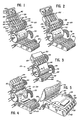
- Figure 1 is a simplified, perspective view of the apparatus for exposing the contents of an envelope in accordance with the teachings of the present invention;
- Figure 2 is a view similar to Figure 1 but showing an envelope being aligned on the first conveyor;
- Figure 3 is a fragmentary, perspective view of the apparatus illustrated in Figure 1 but showing an envelope being fed onto the envelope tipping cylinder;
- Figure 4 is a view similar to Figure 3 but showing the envelope being fed onto the. second conveyor wherein the contents and one of the panels have fallen away from the other panel thereby exposing the contents;
- Figure 5 is an enlarged, fragmentary view of the apparatus of Figure 1 but showing an envelope on the second conveyor with the envelope panels opened and lying on opposite sides of the connected edge portion with the envelope contents thereby exposed on top of one of the envelope panels;
- Figure 6 is a fragmentary, perspective, simplified view of another embodiment of an apparatus for exposing the contents of an envelope;
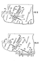
- Figure 7A is an enlarged, fragmentary, side view taken generally along the
plane 7A-7A of Figure 6 with portions of the apparatus cut away to reveal interior structural details; - Figure 7B is a view similar to Figure 7A but with the suction members moved to a position engaged with the envelope stack;
- Figure 8 is an enlarged, fragmentary view taken generally along the plane 8-8 in Figure 6;
- Figure 9 is a simplified, diagrammatic view of a portion of the envelope contents exposing apparatus showing an envelope closing and stacking mechanism; and
- Figures 10-13 are views similar to Figure 9 but showing the various positions of an envelope being moved through the closing and stacking mechanism.
- While this invention is susceptible of embodiment in many different forms, there are shown in the drawings and will herein be described in detail a preferred embodiment of the invention. It should be understood, however, that the present disclosure is to be considered as an exemplification of the principles of the invention and is not intended to limit the invention to the embodiments illustrated and/or described.
- The precise shapes and sizes of the components herein described are not essential to the operation of the disclosed apparatus unless otherwise indicated.
- For ease of description, the disclosed apparatus will be described in a normal operation position, and terms such as upper, lower, horizontal, etc., will be used with reference to this normal operation position. It will be understood, however, that this apparatus may be manufactured, stored, transported and sold in an orientation other than the normal operation position described.
- Much of the apparatus disclosed herein has certain conventional drive mechanisms, vacuum producing mechanisms, conveyor mechanisms, and control mechanisms, the details of which, though not fully illustrated or described, will be apparent to those having skill in the art and an understanding of the necessary functions of such mechanisms.
- One embodiment of an apparatus-that operates in accordance with the teachings of the present invention is illustrated in Figure 1 and designated therein generally by the
reference numeral 20. - The
apparatus 20 includes a first conveyor means such asconveyor 50, an envelope tilting or tippingmember 70, and a second conveyor means orconveyor 80. - The apparatus receives
envelopes 24 seriatim (Figure 2). Specifically, Figure 5 illustrates anenvelope 24 which has been opened and which comprises afirst panel 26 and asecond panel 28. Thepanels line 30 in Figure 5. Theentire contents 32 of the envelope is shown on top of the second panel of the envelope and is thereby exposed for inspection and/or further processing. - When initially fed to the apparatus, each
envelope 24 has the two panels oriented in opposing, parallel relationship, but separated from each other along all but the oneedge portion 30 where the panels remain connected. Theedge portion 30 is typically defined by a straight edge as illustrated, but the present invention would also accommodate an envelope having a non-straight connected edge portion. The apparatus 20performs certain operations upon each envelope to expose the contents of the envelopes as will next be explained. - The principal elements of the
apparatus 20 are illustrated in Figure 1. The support frame and housing, the various controls, the motors and drive mechanisms, and the vacuum producing mechanisms have been omitted for clarity and to permit certain novel elements of the apparatus to be better illustrated and understood. - Envelopes are fed into the
apparatus 20 betweenupper rolls 40 andlower rolls 42. Therolls apparatus 20 may be of any suitable, conventional type and are not part of the present invention. - The envelopes are fed onto the
conveyor 50 which may be a conventional vacuum-transport type conveyor. Specifically, theconveyor 50 may be of the type well known in the art and consisting of a plurality of narrowendless belt strips 46 that are entrained over sprockets or wheels (not visible in Figure 1) on shafts at either end. Such a structure is described in the U.S. Patent No. 4,015,523 and reference is directed thereto. - Vacuum (or more correctly, a reduced pressure) is established within the housing of
conveyor 50 and throughapertures 54 defined in theconveyor surface regions 56 between the endless belt strips 46. The vacuum is drawn within the conveyor. 50 by means of a suitable system (not illustrated) through aconduit 59. - The
belts 46 project a small amount above the adjacent conveyorhousing surface regions 56. The endless belt strips 46 on theconveyor 50 are driven by a suitable conventional drive system (not illustrated in detail) and one such drive system is described and illustrated in the U.S. Patent No. 4,015,523 to which reference is directed. - Located above and toward the bottom end of the
conveyor 50 is agate mechanism 60 which cooperates with theconveyor 50 for aligning an envelope on the conveyor. Thegate 60 includes a plurality offingers 62 positioned on ashaft 64 so as to be in alignment with thelower surface regions 56 between the adjacent edges of the respective belt strips 46 of theconveyor 50 so that the free end of each finger extends slightly below the path defined by the exposed surfaces of thestrips 46. - The
shaft 64 is periodically turned or rotated through just a portion of a full rotation by suitable drive means (not illustrated), such as a conventional rotary solenoid and gear drive-system. Alternatively, other suitable drive means may be used. One such suitable drive means is that illustrated and described in the above-referenced U.S. Patent No. 4,015,523 for the gate means 24 shown in Figures 2 and 6 of that patent. - The
gate 60 is operated to normally maintain thefingers 62 in the path of movement of the envelopes on theconveyor 50. Control means (not illustrated), responsive to the presence of an envelope in the path at thegate 60, are provided for effecting actuation of the gate to raise thefingers 62 out of the path so that theconveyor 50 can move the envelope further along. - Figure 2 illustrates an
envelope 24 on theconveyor 50 and abutting thegate 60 with theconnected edge portion 30 of the envelope aligned generally perpendicular to the direction of the envelope movement along the conveyor. Theedge 30 of theenvelope 24 is thus aligned by thefingers 62 of thegate 60 so that theenvelope 24 will be moved by theconveyor 50, upon raising of thegate 60, onto the envelope tilting means ormember 70 with theenvelope edge 30 generally transverse to the direction of movement. - The envelope tilting or tipping
cylinder 70 is a generally cylindrical member oriented with the longitudinal axis substantially or generally normal to the conveying path defined by theconveyor 50. The cylindrical tipping member orcylinder 70 has an interior chamber portion or portions (not visible in the figures) which may be evacuated, by means of a suitable conventional vacuum system, through theflexible conduit 72. The exterior surface of the tiltingmember 70 has a plurality ofapertures 74 which communicate with the interior vacuum chambers and permit the reduced pressure to be effected at theapertures 74 to the underside of theenvelope 24 as it is fed from theconveyor 50 onto themember 70 as best illustrated in Figure 3. - The
member 70 is rotated (by drive means not completely illustrated) in a direction indicated by arrows 76 in Figure 2. Thus, as best illustrated in Figure 3, when thegate 60 is raised, theenvelope 24 is fed by theconveyor 50 onto the rotating tiltingmember 70 and the first (bottom)panel 26 of the envelope is held against the surface of themember 70 by means of the pressure differential between the reduced pressure within themember 70 and the greater exterior ambient atmospheric pressure. - As best illustrated in Figures 3 and 4, continued rotation of the tilting
member 70 causes the second (upper)panel 28 of theenvelope 24 to fall outwardly away from the grippedfirst panel 26. Theenvelope contents 32 likewise may fall with thesecond panel 28 away from thefirst panel 26 under the influence of gravity. However, in some cases, none or only some of the contents may fall with the second panel. - Preferably a
second conveyor 80 is provided adjacent and below the tiltingmember 70. Thesecond conveyor 80 is substantially identical to thefirst conveyor 50 and includesendless belts 82 spaced apart on a housing mechanism in which vacuum may be drawn through aflexible vacuum tube 84 as best illustrated in Figure 5. Reduced pressure is drawn throughapertures 86 in theconveyor regions 83 between theendless strips 82 to hold the envelope against theconveyor 80. - The endless strips 82 are driven by a suitable drive means (not completely illustrated) in the same manner as the
first conveyor 50 to move the envelope away from the tiltingcylinder 70. As best illustrated in Figure 5, the envelope is pulled along by means of thesecond panel 28 on thesecond conveyor 80 so that thefirst panel 26 of the envelope is pulled off of the tiltingmember 70 and then also lies flat on thesecond conveyor 80. In this orientation, the envelope panels are opened and both panels lie flat on thesecond conveyor 80 on opposite sides of theconnected edge portion 30 with the envelope contents thereby exposed on top of one or both of thepanels entire contents 32 may remain against and on thefirst panel 26. In other cases, some of the contents may fall upon thesecond panel 28 with the remainder of the contents lying on thefirst panel 26. In still other cases, as illustrated, the entire contents may fall on top of thesecond panel 28. - The
conveyor 80 has a length that is chosen to be compatible with the next step in the processing of the envelope and contents. If operators are to inspect and remove thecontents 32, theconveyor 80 might be of sufficient length to allow one or more persons to stand or sit alongside. Alternatively, theconveyor 80 may be of a relatively short length and adapted to feed thecontents 32 to another apparatus or may be adapted to dump thecontents 32 over the end of theconveyor 80 to a suitable receiving mechanism (not illustrated). The openedenvelope 24 may continue along the underside of theconveyor 80 to a point where the vacuum is terminated (as by eliminating the vacuum apertures 86) along a bottom portion of theconveyor 80. In such a case, theenvelope 24 would then fall away from theconveyor 80 and into a suitable envelope receiving means (not illustrated). - Though the
apparatus 20 has been illustrated with a first conveyor, a cylindrical tilting member, and a second conveyor, it is to be realized that these structures are not necessary to expose the contents of an envelope according to the teachings of the present invention. - According to the teachings of the present invention, a method for exposing the contents of an envelope includes the steps of gripping one of the two panels of the envelope and then orienting the envelope so that at least the contents of the envelope are exposed. In the preferred form of the method, the envelope is tipped to orient the connected edge portion of the envelope below the rest of the envelope so as to permit both the ungripped panel and the envelope contents to fall away from the gripped panel under the influence of gravity, thus exposing the envelope contents. However, it is to be realized that the envelope may alternatively be oriented with the connected edge portion trailing the rest of the envelope to permit the upper panel to be raised by suitable means and/or to permit the contents to slide out of the envelope.
- It is to be noted that during the preferred tipping or tilting process, the envelope is tilted about an axis that is located in the gripped panel of the envelope and that is oriented generally parallel to the connected edge portion of the envelope. The first, or gripped envelope may be held in a curved configuration (as illustrated in the embodiment of Figures 1-5) or may be gripped in other configurations, including a generally planar configuration. In any case, in this preferred form of the method, the envelope is tilted with the connected edge moving to a lower elevation than the rest of the envelope.
- As illustrated for the preferred embodiment of the apparatus disclosed herein, the tilting of the envelope may also include an additional, simultaneous translation or movement of the envelope in a path. During this movement of the envelope, the tilting axis will move with the envelope along the envelope movement path. With the apparatus illustrated, the gripped panel is moved by the cylindrical tipping member in a locus defined by a portion of a circular arc. This movement necessarily causes a tilting of the envelope.
- It is to be realized that the tilting of the envelope may occur along any line or axis in the envelope gripped panel. For example, the envelope may be pivoted or tilted about an axis coincident with the connected edge, about an axis coincident with the opened edge opposite the connected edge, or about an axis lying between the opened edge and the connected edge.
- In the embodiment illustrated in Figures 1-5, the envelopes are fed onto a
first conveyor 50 by a conventional feeding mechanism (havingupper rolls 40 and lower rolls 42). It is to be realized that, in some applications, thefirst conveyor 50 may be eliminated, along with thegate 60, and that the envelopes may be fed from a conventional feeder directly on thecylinder 70. - Also, it is to be realized that various types of feeding mechanisms may be provided. One such alternate type of feeding mechanism will next be described with reference to another
embodiment 120 of the apparatus illustrated in Figures 6-8. - As best illustrated in Figure 6, the alternate feeding mechanism includes a tilting member or
cylinder 170 that is similar in many respects tocylinder 70 ofapparatus 20 illustrated in Figure 1. The cylinder is mounted between a pair ofopposed side plates crank disc 175 is mounted for rotation with thecylinder 170, but exterior of theside plate 173. Pivotably mounted to crankdisc 175 with apin 177 is acrank arm 179. - The
crank arm 179 is connected to abar 181 which projects through aguide slot 182 defined in theside plate 173. Though not illustrated,bar 181 may also extend through a similar slot in theother side plate 172 and may be connected to a crank assembly similar to crankdisc 175 andarm 179. - The
bar 181 joins a pair of downwardly projectingsuction members 184. Thesuction members 184 are secured near their top ends by anothercross bar 186. One end ofcross bar 186 is received in aslot 188 defined inside plate 173 and the other end of thecross bar 186 is slidably received in aguide slot 190 defined inside plate 172. Rotation of thecrank disc 175 with the cylindrical member 170 (by a suitable drive mechanism, not illustrated) will drive the suction member support bars 181 and 186 forward in their respective slots in theside plates - The suction members are connected to a suitable vacuum source to provide a vacuum gripping of
envelopes 24 placed in the apparatus as best illustrated in Figures 6 and 7B. Theenvelopes 24 are arranged and aligned in face-to-face relationship to form a batch with at least one of the edges of each envelope in substantial registration with the corresponding edges of the other envelopes in the batch. As illustrated in Figures 6 and 7A, the envelopes in the batch are typically the same size and the bottom edges of the envelopes are supported on a support guide orplate 200. - Each
envelope 24 in the batch has been opened on the opposing vertical side edges and along the top edge to leave a connected edge portion along the bottom. The envelopes may be placed in theapparatus 120 within a suitable holding device 25. Such a device 25 may be removable and may also function as the receiving means in an envelope opening device. Preferably, an envelope receiving means or holding device 25 is filled with a batch ofenvelopes 24 by an envelope opening device with the envelopes arranged in face-to-face relationship. The holding device 25 is then placed in the apparatus illustrated in Figure 6 with the envelopes oriented in parallel vertical planes. - Preferably, the envelope batch holding means or device 25 has a substantially open front. The
apparatus 120 includes a retainingplate 204 which is adjacent the outermost envelope of the batch when the batch is properly placed within the apparatus.Rollers 206 are mounted on theretainer plate 204 to accommodate the removal of each envelope from the batch by thesuction members 184. Also, a motor driven or spring-biasedpiston 205 is provided on the opposite end of the batch to urge the envelopes against theretainer plate 204. - As best illustrated in Figure 7B, the
suction members 184 move against theoutermost envelope 24 of the batch. Suction is applied by suitable means to thesuction members 184, as by drawing a vacuum or otherwise reducing the pressure withinmembers 184, in order that theoutermost envelope 24 attaches to themembers 184 or becomes gripped bymembers 184. As thecylinder 170 continues its rotation, thecrank disc 175 pulls thecrank arm 179 and bar 181 back down along theguide slot 182. At the same time, theupper cross bar 186, being secured to thesuction members 184, is similarly moved rearwardly in itsguide slots suction members 184 are thus finally returned to the vertical orientation illustrated in Figures 6 and 7A, but now gripping anenvelope 24. - The
cylinder 170, like thecylinder 70 in the embodiment illustrated in Figure 1, has a plurality ofvacuum apertures 174 which communicate with interior vacuum chambers and permit a reduced pressure to be effected at theapertures 174 on the surface of thecylinder 170. Thus, as the envelope is carried by thesuction members 184 against thecylinder 170, a leading portion of the envelope becomes gripped by thecylinder 170. - After the leading portion of the envelope has been gripped by the
rotating vacuum cylinder 170, the vacuum in thesuction members 184 is terminated to allow the gripped envelope to be transferred entirely to therotating cylinder 170. - It is seen that when the
envelopes 24 are transferred with thesuction members 184 to thecylinder 170 as described above, the connected edge portion of each envelope becomes the leading portion of the envelope as the envelope is moved to thecylinder 170. Thus, the connected edge portion of the envelope is the first portion of the envelope to attach to thecylinder 170 and, as the cylinder rotates further (in the clockwise direction as viewed in Figure 7A), the upper envelope panel will fall away from thecylinder 170 in the same manner as with the envelopes processed by the first embodiment of theapparatus 20 illustrated in Figures 1-5. - To prevent more than one envelope from being accidentally pulled away from the batch by the
suction members 184, a stripper member ormembers 210 may be provided at the front of the batch on the end ofmember 200. As the outermost envelope is pulled away from the batch by thesuction members 184, the envelope, being flexible, will bend slightly to ride over the stripper 210.-' However, the stripper will prevent the next envelope from being pushed off ofplatform member 200. - A novel means is provided for sensing the thickness of each envelope as it is fed onto the
rotating cylinder 170 and for selectively removing any envelope that does not fall within a predetermined thickness range. Specifically, with reference to Figures 6, 7A and 8, ashaft 220 is mounted over thecylinder 170. Theshaft 220 is received on one end within avertical guide slot 222 defined inside plate 173 and on the other end within avertical guide slot 224 defined inside plate 172. A pair ofbrass rollers shaft 220. Thus, as an envelope is carried around on thecylinder 170, it passes between the nips defined by thecylinder 170 and thebrass rollers shaft 220, on which thebrass rollers vertical slots shaft 220 will move upwardly when a thick envelope is carried on thecylinder 170 and will move downwardly when a thin envelope is carried on thecylinder 170. - As best illustrated in Figure 8, the end of the
shaft 220 passing through theside plate 172 extends beyondside plate 172 and is received within a slot 230 defined within afirst portion 232 of acrank arm 234. Thecrank arm 234 is pivotably mounted about apin 236 to theside plate 172 and has a downwardly extendingportion 238. Preferably, theportion 238 is considerably longer than theportion 232 for reasons that will be explained thereafter. - A pair of
limit switches portion 238 of the angled crankarm 234 and are adapted to be engaged by thecrank arm portion 238. The limit switches 240 and 242 are suitably connected in an electrical control circuit so that, upon being engaged byarm 234, they actuate the envelope deflector mechanisms that are described in detail hereinafter. - With continued reference to Figures 6 and 8, it can be seen that when an envelope is not passing under the
rollers rollers cylinder 170. Theroller shaft 220 is then in the lowest position inslot 224 and thecrank arm 234 is then engaged with theswitch 242. If an envelope is carried between the nips of therollers cylinder 170, theroller shaft 220 will be moved upwardly in itsslot 224 and will cause the angled crankarm 234 to pivot (in a clockwise direction with reference to Figure 8) away from theswitch 242. If the envelope has less than a predetermined thickness, thearm 234 will not be pivoted sufficiently to be disengaged fromswitch 242. If the thickness of the envelope is in the desired range, thearm 234 will be disengaged from switch 242!but will not engageswitch 240. On the other hand, if the thickness of an envelope is relatively great, then theshaft 220 will move much further upwardly inslot 224 and thecrank arm 234 will be moved againstswitch 240. - By appropriate mounting of the
switches switch crank arm portion 232 is considerably less than the length of thecrank arm portion 238. Thus, a small movement of thecrank arm portion 232 will cause a relatively large movement of thecrank arm portion 238. - The mechanism for selectively rejecting envelopes not meeting the thickness criteria as sensed by the
switches cylinder 170 is seen to have a pair ofcircumferential grooves 250. A pair ofdeflector arms 252 are adapted to be received within thegrooves 250 and are adapted to be moved between a first position seated within thegrooves 250 and a second position (illustrated in dashedline 7A) spaced away from thecylinder 170. To this end, thedeflector members 252 are secured to ashaft 260 which is mounted toside plates solenoid rotary operator 262 is mounted to theside plate 173 and is operatively engaged with theshaft 260. The control circuit of thesolenoid 262 is suitably connected with theswitches switches crank arm 234, thedeflector members 252 are held within thecylinder grooves 250. With thedeflector members 252 in this position, the envelopes will pass over thedeflector members 252 and be carried by thecylinder 170 onto thedownstream conveyor 180. - However, if either one of the
switches crank 234, thesolenoid 262 is actuated to move thedeflector arms 252 to the second position (illustrated in dashed line in Figure 7A) so as to guide the envelope to the underside of thecylinder 170. A suitable receiving bin orstructure 276 may be provided beneath thecylinder 170 for receiving the rejected envelopes. To ensure that the rejected envelopes will fall away from thecylindrical member 170 and into the receivingbin 276, a pair ofsuitable stripper fingers 278 may be provided beneath thecylinder 170. The distal ends of thestripper fingers 278 are received within thegrooves 250 of thecylinder 170. - Though the
cylinder 170 may have a plurality ofvacuum apertures 174 extending around the circumference, it has been found that two rows ofapertures 174 will function to satisfactorily hold an envelope to thecylinder 170. Preferably, one row of apertures extends across the length of thecylinder 170 in a line generally parallel to the longitudinal axis of the cylinder. A second row of apertures is provided on the cylinder parallel to z-.nd spaced from the first row of apertures. The first row of apertures is adapted to hold the leading edge portion (i.e., the connected edge portion) of the envelope. The second row of apertures is adapted to hold the trailing edge portion of the envelope. Preferably, the vacuum in each row of apertures is terminated as that row of apertures moves adjacent thedeflector fingers 252. Specifically, and with reference to Figure 7A, the vacuum is terminated when each row of apertures is moved by therotating cylinder 170 to the "4 c'clock" position. - A means for stacking opened and emptied envelopes may be provided with the apparatus as best illustrated in Figures 9-13. Figure 9 illustrates an
envelope 24 on aconveyor 280 substantially identical toconveyor 80 discussed above with reference to the first embodiment illustrated in Figure 1 or to theconveyor 180 of the embodiment illustrated in Figures 6-7B. Thus,conveyor 280 is located downstream of the rotating vacuum cylinder and operators would typically remove the contents from the openedenvelopes 24 while theenvelopes 24 are on theconveyor 280. Each empty envelope continues to travel on theconveyor 280 with thefirst panel 26 trailing, but connected to, the leadingsecond panel 28 alongedge 30. - At the end of the
conveyor 280, adrive roller 282 is provided above theconveyor 280. Theroller 282 is driven by suitable means (not illustrated) to rotate in a direction to grip and pull theenvelope 224 between the nip defined by theroller 282 and aconveyor 280. - A deflecting means 286 is spaced from the end of the
conveyor 280 in the path of the openedenvelope 24 and presents a deflectingsurface 288 against which thesecond panel 28 of theenvelope 24 impinges. - As best illustrated in Figures 10 and 11, the second panel of the envelope rides up the deflecting
surface 288. Preferably, the deflecting means has an upper portion presenting an outwardly extendingimpingement surface 290 against which the distal end of thesecond panel 28 may ultimately impinge. - As best illustrated in Figure 11, an abutment means 292 is provided below the deflecting means 286 for presenting an
abutment surface 294 against which the envelope connectededge portion 30 andfirst panel 26 fall and slide downwardly along. Also, a roller means 304 is provided adjacent the deflecting means 286 and abutment means 292. The roller means includes aroller 306 which is driven by suitable means (not illustrated) to rotate (in the counterclockwise direction as viewed in Figure 11) against thesecond panel 28 of the envelope. - As best illustrated in Figures 11 and 12, the
envelope panels connected edge portion 30. Therotating roller 306 engages the back of thepanel 28 and propels the envelope along the downwardly slopingabutment surface 294 thereby closing the first and second panels of the envelope and moving the envelope off of the abutment means 294. - Preferably, and as best illustrated in Figure 13, a suitable receiving means or
station 310 is provided adjacent and below theabutment surface 294 for receiving the closedempty envelopes 24. Specifically, thestation 310 includes a suitable cage constructed fromrods 312 and adapted to receive theenvelopes 24 in a stack. The stack is supported by amovable bottom plate 314 which is preferably driven by a suitable mechanism (not illustrated) in a downward direction as the stack height increases. This maintains the top of the stack at a substantially constant elevation. - From the foregoing, it will be observed that numerous variations:and modifications may be effected without departing from the true spirit and scope of the novel concept of the invention. It is to be understood that no limitation with respect to the specific apparatus illustrated herein is intended or should be inferred. It is, of course, intended to cover by the appended claims all such modifications as fall within the scope of the claims.
Claims (9)
1. The method for exposing the contents of an envelope which has two opposing panels wherein the panels have been separated from each other along all but one edge portion where the panels remain connected, said method comprising the steps of:
(a) gripping at least one of said panels; and
(b) while continuing to grip said one panel, moving said envelope to an orientation wherein the other envelope panel falls away from said gripped panel to expose said contents.
2. The method in accordance with claim 1 in which step (b) includes tipping the envelope to orient the connected edge portions of the envelope below the adjacent portion of the envelope to permit the ungripped panel to fall away from the gripped panel under the influence of gravity to thereby expose the envelope contents.
3. The method in accordance with claim 2 in which step (b) includes tilting the envelope above a receiving means for receiving the ungripped panel as it falls away from the gripped panel against the receiving means.
4. The method in accordance with claim 2 in which step (b) includes moving at least said gripped panel in a locus defined by a portion of a circular arc with the connected edge portion of the envelope leading the movement of the envelope in said locus.
5. The method for exposing the contents of an envelope which has first and second opposing panels wherein the panels have been separated from each other along all but one edge portion where the panels remain connected, said method comprising the steps of:
(a) gripping said first paneli
(b) moving the envelope in a first path to at least momentarily orient the connected edge portion in the first path below the elevation of the adjacent portions of the envelope whereby said second panel falls outwardly away from said gripped first panel about said connected edge portion;
(c) arresting the falling movement of said ungripped second panel in a second path; and
(d) moving said envelope along said second path with said first and second panels opened and lying in said second path on opposite sides of said connected edge portion with the envelope contencsthereby exposed on at least one of said panels.
6. An apparatus (20) for exposing the contents (32) of an envelope (24) which has two opposing panels (26, 28) wherein the panels have been separated from each other along all but one straight edge portion (30) where the panels remain connected, said apparatus comprising:
(a) means (60, 62) for gripping at least one of said panels (26, 28); and
(b) means (70) for tilting said envelope (24) to an orientation wherein the other (28) of said envelope panels falls away from said gripped panel (26) to expose the contents (32) while the gripping of said one panel is continued.
7. An apparatus for feeding envelopes seriatim which have been arranged and aligned in face-to-face relationship to form a batch with at least one of the edges of each envelope in substantial registration with the corresponding edges of the other envelopes in the batch, said apparatus comprising:
(a) holder means (200, 205, 206) for holding said batch of envelopes (24) with at least a portion of the panel of an outermost envelope (24) being exposed;
(b) means (184.) for attaching to the exposed portion of an outermost panel of the batch; and
(c) means (170, 179) for moving said attaching means (184) and an attached envelope (24) to transfer said envelope (24) from said batch to a discharge position.
8. A method for closing opened, emptied envelopes wherein each envelope has first and second panels separated from each other along all but one straight edge portion where the panels remain connected and wherein the first and second panels are opened and lie on opposite sides of said connected edge portion, said method comprising the steps of:
(a) supporting and moving said empty envelopes along a first path seriatim with said first and second panels positioned on opposite sides of said connected edge portion and with said first panel trailing said second panel;
(b) deflecting said second panel upwardly and terminating the support of said first panel to permit said envelope to fall downwardly with the envelope oriented with said connected edge portion below the remaining portions of the envelope; and
(c) deflecting said connected edge portion to guide said connected edge portion and the first panel downwardly along a second path whereby the first and second panels are closed.
9. An apparatus for closing opened, emptied envelopes wherein each envelope (24) has first and second panels (26, 28) separated from each other along all but one straight edge portion (30) where the panels (26, 28) remain connected and wherein the first and second panels (26, 28) are opened and lie on opposite sides of said connected edge portion (30), said apparatus comprising:
(a) means (280) for moving said empty envelopes (24) along a path seriatim with said first and second panels (26, 28) positioned on opposite sides of said connected edge portion (30) and with said first panel (26) trailing said second panel (28);
(b) deflecting means (286) in said path for presenting a deflecting surface (288) against which said second panel (28) impinges and moves upwardly along;
(c) abutment means (292) be.low said deflecting means (286) for presenting an abutment surface (294) against which said connected edge portion (30) and said first panel (26) fall and slide downwardly along; and
(d) rotating roller means (304), adjacent said deflecting means (286) and said abutment means (292), for engaging said second panel (28) and propelling said envelope (24) along said abutment surface (294) to close said first and second panels (26, 28).
Applications Claiming Priority (2)
| Application Number | Priority Date | Filing Date | Title |
|---|---|---|---|
| US06/189,227 US4373848A (en) | 1980-09-22 | 1980-09-22 | Method and apparatus for exposing contents of an opened envelope with gravity assist |
| US189227 | 1980-09-22 |
Publications (2)
| Publication Number | Publication Date |
|---|---|
| EP0048485A2 true EP0048485A2 (en) | 1982-03-31 |
| EP0048485A3 EP0048485A3 (en) | 1982-06-09 |
Family
ID=22696478
Family Applications (1)
| Application Number | Title | Priority Date | Filing Date |
|---|---|---|---|
| EP81107506A Withdrawn EP0048485A3 (en) | 1980-09-22 | 1981-09-21 | Method and apparatus for exposing contents of an opened envelope with gravity assist |
Country Status (3)
| Country | Link |
|---|---|
| US (1) | US4373848A (en) |
| EP (1) | EP0048485A3 (en) |
| JP (1) | JPS57107900A (en) |
Cited By (9)
| Publication number | Priority date | Publication date | Assignee | Title |
|---|---|---|---|---|
| EP0459589A1 (en) * | 1990-05-30 | 1991-12-04 | Hadewe B.V. | Apparatus and method for removing contents from an envelope |
| EP0565837A1 (en) * | 1992-04-09 | 1993-10-20 | Stielow GmbH | Method and apparatus for removing contacts of envelopes |
| EP0571308A1 (en) * | 1992-05-22 | 1993-11-24 | Opex Corporation | Apparatus and method for automated mail extraction and remittance processing |
| US5336034A (en) * | 1991-11-29 | 1994-08-09 | Hadewe B. V. | Method and apparatus for unpacking contents from envelopes |
| NL9301114A (en) * | 1993-06-25 | 1995-01-16 | Berthom Mail Systems Benelux B | Method and device for opening envelopes and separating their contents |
| US5460273A (en) * | 1986-09-05 | 1995-10-24 | Opex Corporation | Apparatus for the automated processing of bulk mail having varied characteristics |
| EP0681925A2 (en) * | 1994-05-12 | 1995-11-15 | Frank Grützmacher | Inserts station for envelope inserter |
| US5813668A (en) * | 1994-03-31 | 1998-09-29 | Stielow Gmbh & Co. | Apparatus for conveying and staggering envelope contents for review by an operator |
| US5842693A (en) * | 1986-09-05 | 1998-12-01 | Opex Corporation | Automated mail extraction and remittance processing |
Families Citing this family (16)
| Publication number | Priority date | Publication date | Assignee | Title |
|---|---|---|---|---|
| US4739606A (en) * | 1982-06-10 | 1988-04-26 | Hammermill Paper Company | Conveyor means of system for in-line processing of envelopes and the like |
| US4792249A (en) * | 1985-09-20 | 1988-12-20 | Creative Associates Limited Partnership | Vacuum paper transport system for printer |
| US4715164A (en) * | 1986-02-28 | 1987-12-29 | Pitney Bowes Inc. | High speed envelope flap opener |
| US5240116A (en) * | 1986-09-05 | 1993-08-31 | Opex Corporation | Method and apparatus for determining the orientation of a document |
| US4863037A (en) * | 1986-09-05 | 1989-09-05 | Opex Corporation | Apparatus for the automated processing of bulk mail and the like |
| US5464099A (en) * | 1986-09-05 | 1995-11-07 | Opex Corporation | Method for the automated processing of documents and bulk mail |
| US4909021A (en) * | 1988-12-01 | 1990-03-20 | Barbour William P | Automatic envelope opener |
| US5125214A (en) * | 1989-04-14 | 1992-06-30 | Bell & Howell Company | Inserter station for envelope inserting |
| US5125215A (en) * | 1989-04-14 | 1992-06-30 | Bell & Howell Phillipsburg Co. | Envelope flap opener |
| US5475966A (en) * | 1994-06-10 | 1995-12-19 | Electrocom Automation, L.P. | Apparatus for unfolding documents |
| DE19755058C1 (en) * | 1997-12-11 | 1999-08-12 | Lohmann Therapie Syst Lts | Device with suction openings for transferring flat products to a conveyor belt |
| WO1999055607A1 (en) * | 1998-04-29 | 1999-11-04 | Kansa Corporation | Opening wheel for high speed inserter |
| US6442914B1 (en) | 1999-11-29 | 2002-09-03 | Rapid Automated Systems, Inc. | Tagging system for inserting tags into plant containers |
| US6725752B1 (en) * | 2001-10-22 | 2004-04-27 | Catawa, Inc. | Mail processing machine |
| US7300051B1 (en) * | 2003-10-24 | 2007-11-27 | Stolle Machinery Company, Llc | Rippler for a paper deliverer |
| FR2876058B1 (en) * | 2004-10-01 | 2008-04-18 | Gianfranco Passoni | METHOD FOR AUTOMATICALLY LOADING LOW-DIMENSIONAL PIECES, ESPECIALLY DOCUMENTS, AND DEVICE FOR IMPLEMENTING SAID METHOD |
Citations (2)
| Publication number | Priority date | Publication date | Assignee | Title |
|---|---|---|---|---|
| US3238926A (en) * | 1961-12-12 | 1966-03-08 | William F Huck | Envelope opening machine |
| US4142430A (en) * | 1977-08-22 | 1979-03-06 | Amer-O-Matic Corp. | Envelope opener |
Family Cites Families (5)
| Publication number | Priority date | Publication date | Assignee | Title |
|---|---|---|---|---|
| US2159987A (en) * | 1937-07-29 | 1939-05-30 | William L Suiter | Paper stuffing machine |
| US4015523A (en) * | 1972-09-01 | 1977-04-05 | Aes Technology Systems, Inc. | Method and apparatus for feeding and printing documents |
| CH598110A5 (en) * | 1975-10-10 | 1978-04-28 | Gretag Ag | |
| US4200275A (en) * | 1977-11-02 | 1980-04-29 | Gruner & Jahr Ag & Co. | Collating machine |
| US4121716A (en) * | 1977-12-12 | 1978-10-24 | Pitney-Bowes, Inc. | Doubles and thickness detector and sorter |
-
1980
- 1980-09-22 US US06/189,227 patent/US4373848A/en not_active Expired - Lifetime
-
1981
- 1981-09-21 EP EP81107506A patent/EP0048485A3/en not_active Withdrawn
- 1981-09-21 JP JP56149300A patent/JPS57107900A/en active Pending
Patent Citations (2)
| Publication number | Priority date | Publication date | Assignee | Title |
|---|---|---|---|---|
| US3238926A (en) * | 1961-12-12 | 1966-03-08 | William F Huck | Envelope opening machine |
| US4142430A (en) * | 1977-08-22 | 1979-03-06 | Amer-O-Matic Corp. | Envelope opener |
Cited By (16)
| Publication number | Priority date | Publication date | Assignee | Title |
|---|---|---|---|---|
| US5518121A (en) * | 1986-09-05 | 1996-05-21 | Opex Corporation | Method for automated mail extraction and remittance processing |
| US5441159A (en) * | 1986-09-05 | 1995-08-15 | Opex Corporation | Apparatus for handling documents for delivery to remittance processing equipment |
| US5842693A (en) * | 1986-09-05 | 1998-12-01 | Opex Corporation | Automated mail extraction and remittance processing |
| US5439118A (en) * | 1986-09-05 | 1995-08-08 | Opex Corporation | Apparatus for extracting documents from envelopes |
| US5460273A (en) * | 1986-09-05 | 1995-10-24 | Opex Corporation | Apparatus for the automated processing of bulk mail having varied characteristics |
| US5310062A (en) * | 1986-09-05 | 1994-05-10 | Opex Corporation | Apparatus for automated mail extraction and remittance processing |
| EP0459589A1 (en) * | 1990-05-30 | 1991-12-04 | Hadewe B.V. | Apparatus and method for removing contents from an envelope |
| US5175979A (en) * | 1990-05-30 | 1993-01-05 | Hadewe B.V. | Apparatus and method for removing contents from an envelope |
| US5336034A (en) * | 1991-11-29 | 1994-08-09 | Hadewe B. V. | Method and apparatus for unpacking contents from envelopes |
| US5440861A (en) * | 1992-04-09 | 1995-08-15 | Stielow Gmbh & Co. Kg | Method and apparatus for emptying envelopes |
| EP0565837A1 (en) * | 1992-04-09 | 1993-10-20 | Stielow GmbH | Method and apparatus for removing contacts of envelopes |
| EP0571308A1 (en) * | 1992-05-22 | 1993-11-24 | Opex Corporation | Apparatus and method for automated mail extraction and remittance processing |
| NL9301114A (en) * | 1993-06-25 | 1995-01-16 | Berthom Mail Systems Benelux B | Method and device for opening envelopes and separating their contents |
| US5813668A (en) * | 1994-03-31 | 1998-09-29 | Stielow Gmbh & Co. | Apparatus for conveying and staggering envelope contents for review by an operator |
| EP0681925A2 (en) * | 1994-05-12 | 1995-11-15 | Frank Grützmacher | Inserts station for envelope inserter |
| EP0681925A3 (en) * | 1994-05-12 | 1996-06-19 | Frank Gruetzmacher | Inserts station for envelope inserter. |
Also Published As
| Publication number | Publication date |
|---|---|
| JPS57107900A (en) | 1982-07-05 |
| EP0048485A3 (en) | 1982-06-09 |
| US4373848A (en) | 1983-02-15 |
Similar Documents
| Publication | Publication Date | Title |
|---|---|---|
| EP0048485A2 (en) | Method and apparatus for exposing contents of an opened envelope with gravity assist | |
| US3979884A (en) | Mail extracting and sorting desk | |
| EP0045436B1 (en) | Vacuum document feeder | |
| EP0103633B1 (en) | Plate feed apparatus | |
| ES8203306A1 (en) | Continuous sheet collection and discharge system | |
| US20080169056A1 (en) | Method for joining adhesive tape and apparatus using the method | |
| JPS58172132A (en) | Extractor for sheet material | |
| EP0525756A1 (en) | Apparatus for cutting and removing package material | |
| US5096360A (en) | Envelope opener and load separator | |
| US5061146A (en) | Envelope opener and load separator | |
| US4649694A (en) | Envelope contents extraction system | |
| US4447053A (en) | Device for separating individual sheets combined into a stack | |
| US6929257B2 (en) | Slip sheet capture mechanism and method of operation | |
| EP0459589B1 (en) | Apparatus and method for removing contents from an envelope | |
| US5440861A (en) | Method and apparatus for emptying envelopes | |
| US3854613A (en) | Batch to continuous flow mail handling | |
| EP0545480B1 (en) | Method and apparatus for unpacking contents from envelopes | |
| US5188504A (en) | Envelope opener and load separator | |
| USRE32328E (en) | Mail extracting and sorting desk | |
| US4262471A (en) | Envelope processing machine | |
| KR20000064417A (en) | Valve Bag Transfer Device for Filling Device | |
| US3994389A (en) | Mail stack feed control | |
| US3863789A (en) | Mail tray unloading | |
| WO1995013236A1 (en) | Remittance processing apparatus and method | |
| US6176364B1 (en) | Device for simplified vertical loading of an X-ray cassette into a transport receptacle of a processing apparatus for X-ray cassettes |
Legal Events
| Date | Code | Title | Description |
|---|---|---|---|
| PUAI | Public reference made under article 153(3) epc to a published international application that has entered the european phase |
Free format text: ORIGINAL CODE: 0009012 |
|
| AK | Designated contracting states |
Designated state(s): DE FR GB IT |
|
| PUAL | Search report despatched |
Free format text: ORIGINAL CODE: 0009013 |
|
| AK | Designated contracting states |
Designated state(s): DE FR GB IT |
|
| STAA | Information on the status of an ep patent application or granted ep patent |
Free format text: STATUS: THE APPLICATION IS DEEMED TO BE WITHDRAWN |
|
| 18D | Application deemed to be withdrawn |
Effective date: 19830518 |
|
| RIN1 | Information on inventor provided before grant (corrected) |
Inventor name: BISHOP, CLIFF |