EP0034417A2 - Support for backflushable filter media - Google Patents
Support for backflushable filter media Download PDFInfo
- Publication number
- EP0034417A2 EP0034417A2 EP81300319A EP81300319A EP0034417A2 EP 0034417 A2 EP0034417 A2 EP 0034417A2 EP 81300319 A EP81300319 A EP 81300319A EP 81300319 A EP81300319 A EP 81300319A EP 0034417 A2 EP0034417 A2 EP 0034417A2
- Authority
- EP
- European Patent Office
- Prior art keywords
- filter
- layer
- media
- pleats
- staples
- Prior art date
- Legal status (The legal status is an assumption and is not a legal conclusion. Google has not performed a legal analysis and makes no representation as to the accuracy of the status listed.)
- Ceased
Links
- 239000000463 material Substances 0.000 claims abstract description 18
- 125000004122 cyclic group Chemical group 0.000 claims abstract description 6
- 239000002184 metal Substances 0.000 claims description 44
- 229910052751 metal Inorganic materials 0.000 claims description 44
- 239000012530 fluid Substances 0.000 claims description 19
- 239000011148 porous material Substances 0.000 claims description 3
- 238000005245 sintering Methods 0.000 claims description 3
- 239000004744 fabric Substances 0.000 claims 1
- 239000000203 mixture Substances 0.000 claims 1
- 125000006850 spacer group Chemical group 0.000 claims 1
- 238000004140 cleaning Methods 0.000 abstract description 5
- 238000001914 filtration Methods 0.000 description 13
- 239000000835 fiber Substances 0.000 description 8
- PXHVJJICTQNCMI-UHFFFAOYSA-N Nickel Chemical compound [Ni] PXHVJJICTQNCMI-UHFFFAOYSA-N 0.000 description 2
- 239000000356 contaminant Substances 0.000 description 2
- 238000005336 cracking Methods 0.000 description 2
- 238000004519 manufacturing process Methods 0.000 description 2
- 230000002028 premature Effects 0.000 description 2
- 238000012360 testing method Methods 0.000 description 2
- 239000004753 textile Substances 0.000 description 2
- 229910045601 alloy Inorganic materials 0.000 description 1
- 239000000956 alloy Substances 0.000 description 1
- 238000010420 art technique Methods 0.000 description 1
- 238000005056 compaction Methods 0.000 description 1
- 238000010276 construction Methods 0.000 description 1
- 238000005520 cutting process Methods 0.000 description 1
- 230000001419 dependent effect Effects 0.000 description 1
- 238000011156 evaluation Methods 0.000 description 1
- 230000002452 interceptive effect Effects 0.000 description 1
- 150000002739 metals Chemical class 0.000 description 1
- 238000000034 method Methods 0.000 description 1
- 238000012986 modification Methods 0.000 description 1
- 230000004048 modification Effects 0.000 description 1
- 229910052759 nickel Inorganic materials 0.000 description 1
- 229920000642 polymer Polymers 0.000 description 1
- 238000011045 prefiltration Methods 0.000 description 1
- 230000002787 reinforcement Effects 0.000 description 1
- 238000012552 review Methods 0.000 description 1
- 229920002545 silicone oil Polymers 0.000 description 1
- 238000001228 spectrum Methods 0.000 description 1
- 239000010935 stainless steel Substances 0.000 description 1
- 229910001220 stainless steel Inorganic materials 0.000 description 1
- 229910000601 superalloy Inorganic materials 0.000 description 1
- 230000002195 synergetic effect Effects 0.000 description 1
- 238000007514 turning Methods 0.000 description 1
- 210000002268 wool Anatomy 0.000 description 1
Images


Classifications
-
- B—PERFORMING OPERATIONS; TRANSPORTING
- B01—PHYSICAL OR CHEMICAL PROCESSES OR APPARATUS IN GENERAL
- B01D—SEPARATION
- B01D29/00—Filters with filtering elements stationary during filtration, e.g. pressure or suction filters, not covered by groups B01D24/00 - B01D27/00; Filtering elements therefor
- B01D29/11—Filters with filtering elements stationary during filtration, e.g. pressure or suction filters, not covered by groups B01D24/00 - B01D27/00; Filtering elements therefor with bag, cage, hose, tube, sleeve or like filtering elements
- B01D29/13—Supported filter elements
- B01D29/15—Supported filter elements arranged for inward flow filtration
- B01D29/21—Supported filter elements arranged for inward flow filtration with corrugated, folded or wound sheets
-
- B—PERFORMING OPERATIONS; TRANSPORTING
- B01—PHYSICAL OR CHEMICAL PROCESSES OR APPARATUS IN GENERAL
- B01D—SEPARATION
- B01D29/00—Filters with filtering elements stationary during filtration, e.g. pressure or suction filters, not covered by groups B01D24/00 - B01D27/00; Filtering elements therefor
- B01D29/62—Regenerating the filter material in the filter
- B01D29/66—Regenerating the filter material in the filter by flushing, e.g. counter-current air-bumps
Definitions
- This invention relates to filter elements, and more particularly, to filter elements used in backflushable filter units wherein the filters suffer' from premature failure due to the filtering-cleaning cycle imposed thereon.
- the invention comprehends a means for limiting this premature failure by incorporating a novel support system during the manufacturing of the filter.
- a backflushable filter unit having a plurality of filter elements is taught.
- the filter elements therein are depicted as being cylindrical with pleated filter media being secured to the end caps of the filter elements.
- the preferred filter media for filtering polymers is mentioned as a metal fibre depth filter media wherein the metal fibres have a diameter from about 1 micron to about 50 microns and the media is sintered.
- the flow of contaminated fluid is usually from outside the filter element into the centre of the element and then out through the centre of the filter housing.
- the flow is pre- selectedly reversed so that some of the cleaned fluid is used for flowing from inside the filter element to its outside thereby cleaning the filter media.
- the filters are on-stream filtering for a preselected period of time and then selectively switched off-stream either individually or in pairs being cleaned for a preselected period of time.
- the cleaning period or time required to clean the filters is dependent upon:
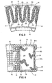
- the filtering and cleaning causes the pleated filter media of the filter elements to be subjected to cyclic pressure and flow. It has been found that under certain circumstances, such as a high differential pressure across the filter media caused by a high viscosity fluid being filtered, that the crowns of the pleats of some of the elements in a backflushable unit were cracking or splitting such as depicted in the photograph of Figure 1.
- This invention relates to filter elements, and more particularly, filter elements that are used in backflushable filtering units and contemplates a means for preventing the crowns of the pleats of the filter elements from cracking or splitting because the media is subjected to repeated cycles of filtering and backflushing.
- FIG. 2 A small perspective representation of a filter element is shown in Figure 2 with Figure 3 depicting a segment of the lower portion of the filter element of Figure 2 taken along line B-B.
- the filter media 20 has pleats 27 with crowns 21 and apexes 22.
- the filter media 20 is secured to 'the end caps 11 and 12 by bonding means 19 such as taught in United States Patent No. 4,114,794.
- the upper end cap 11 has a forward lip 13 and an inner lip 15 with gap 17 between the apexes 22 and lip 15.
- the lower cap 12 has a forward lip 14 and an inner lip 16 with gap 18 between the apex 22 and the lip 16.
- the crown 21 is extremely close to the forward lips 13 and 14 and in some instances when the bonding means 19 actually falls over the edge of the lip the very top edge of the crown 21 can be secured at 21a and 21b.
- the filter element 10 will be of any size compatible with the filter housing used to hold it.
- the filter media pleats 27 are forced together such as shown in Figure 6; the arrows indicating the path of the flow of the fluid.
- the filtering and backflushing cycle causes the pleats 27 to move in and out, mostly at their centre 28, in a diaphragmic movement without breaking their seal with the bonding means to the end caps.
- the top crown 21a and bottom crown 21b are restricted from movement due to the relative closeness to and support provided by lips 13 and 14. It is therefore believed that the location of maximum stress due to this diaphragmic movement is located in the crown 21 and possibly at the centre 21c.
- FIG. 1 depicts a portion of part of a filter element used in a backflushable filter unit such as the backflushable unit shown in United States Patent No. 3,994,880.
- a cross-sectional view of a split crown 21 similar to that shown in Figure 1 is shown in Figure 6 at 40.
- the filter unit becomes inoperable because contaminated fluid can pass through this breach without being filtered. It has been ascertained that the splitting crowns will occur more when fluid having a viscosity of approximately 1000 poise or more is being filtered and the pressure drop across the filter media is about 150 psia or more.
- the filter media 20 can be made from a metal fibre web material that is sintered.
- This filter media 20 may be faced on its outer surface 23 by an outer metal wire screen 30.
- the media 20 may also be faced on the inner surface 24 by a metal wire screen 31.
- These wire screens 30 and 31 are generally lightweight metal screens; typically, these screens are 24 x 24 mesh made of 11 mil wire, 16 x 16 mesh made of 18 mil wire and 10 x 10 wire mesh made from 25 mil wire.
- Expanded metal sheets having a thickness of from about 20 mils to about 30 mils may be substituted for the metal screen wire.
- the size of the screen or expanded metal is predicated on (1) the size of the filter element, (2) the number of pleats of the element and (3) the size of a pleat in order to be compatible therewith.
- an anti-bellowing means that prevents the diaphragmic movement of the pleats 22 may be comprised of a three-dimensional, randomly oriented array of metal staples forming a layer that can be placed adjacent the outer surface 23 of the media 20.
- a layer 50 is shown in Figures 7 and 8 comprising a plurality of staples.
- the term "staple” means short strands of predetermined length range (although they can be random lengths) of fibres, strands, filaments and of the size range that is common with the full spectrum of textile staple fibres both in length and diameter.
- the staple fibres of predetermined length range are staple metal fibres, cut wires and metal cuttings including cut metal wool and metal turnings, but not limited thereto. It is fully contemplated that although the length of the staples are predetermined range they can also be of random length in a particular layer.
- the staples of the layer can have a length ranging from 1/4 inch to 6 inches (similar to textile staple fibres) and more preferably, about 3/8 inch to 1-1/4 inch.
- the diameter of the staples can vary anywhere from about 20 microns to about 250 microns; the diameter of the fibres used in a layer 50 are partially predicated by (1) the size of the individual pleat area, (2) the number of pleats in filter element, (3) the fluid to be filtered, (4) the pressure drop across the filter, and (5) the viscosity of the contaminated fluid to be filtered.
- the layer 50 can be made of textile-type metal staples and made into a nonwoven (in a classical sense) metal layer. It is also fully contemplated that the layer can be made of kinked wire staples.
- the layer 50 exhibits flexibility and some resiliency which is, in part, controlled by the size of the staples. Layer 50 also can be sintered in order to bond some of the staples to each other.
- Some of the techniques for making such a metal layer and the fibres contained therein can be found in United States Patent Nos. 3,379,000; Re 28,470; 3,505,038; 3,505,039; 3,277,564; 3,394,213; 3,469,297; 3,504,516; 3,54 0 ,114; 3,632,027; 3,705,021; 3,977,069; 3,977,070; 4,118,845; just to name a few.
- a metal layer 50 is made from metal staples 51, such as precut lengths of wire that are subsequently kinked, metal fibres or cut metal shavings; the metal staples are sintered in the layer at their points where the staples touch each other.
- the sintering can be accomplished as described in some of the prior art patents previously referred to; the temperatures and furnace atmospheres depending on the type of metal to be sintered.
- the layer 50 and the filter media 20 should be made of compatible materials, and when the filter media and layer are made of metals, they can be made of such materials such as stainless steel, super alloys, nickel based alloys, and the like, but not limited thereto.
- the selection of the materials for the layer 50 and the media 20 is predicated by the fluid to be filtered and the contaminant to be removed from the fluid.
- the layer 50 is sintered, it is rolled to the desired thickness in density.
- the .layer 50 preferably has a density from about 10% to .about 30% and more preferably 14% to 20%. Obviously ' the layer must have a pore size that is greater than the filter material otherwise it will perform, too much, as a prefilter layer.
- a preferred thickness range of the layer is from about 1/32 inch (31 mils) to about 3/32 inch (93 mils) and, of course, depends on the distance between the outer surfaces of the pleats which may or may not include adjacent screen material.
- This layer 50 is packed between the outer- facing pleats 27 and not only reinforces the filter media but provides a semi-rigid layer 50 between the outer surface 23 of the pleats 27, as shown in Figure 9.
- This porous layer 50 prevents the outward bellowing or outward diaphragmic movement of the media 20 when it is being backflushed.
- the density of the layer 50 is selected so that it does not interfere with the filtering aspects of the media 20 or the subsequent backflushing that the media 20 experiences.
- the layer 50 can easily be pleated (after it is sintered and compressed) along with the media 20 and the screen wire 30 (if the screen wire is used).
- the filter element is assembled in a manner such as shown in United States Patent No. 4,114,794, although other means of bonding the media and the layer to the end caps 11 and 12 are fully contemplated herein.
- the layer 50 is tightly compacted on itself such as shown in Figure 9.
- the compacted metal staple layer 50 has very little surface resiliency since it is compacted after sintering; thus, it is defined as having the ability to resist compaction in its thinner dimension "a" (as shown in Figure 8).
- the layer 50 ably prevents the anti-bellowing or diaphragmic movement of the media once the filter element containing the invention is assembled and placed into use.
- a layer 50a similar to layer 50, can be positioned adjacent the inner surface 24 of the media 20.
- This lightweight, low density porous layer 50a supports the media 20 from the inward anti-bellowing or diaphragmic movement when the filter element is in the filtering mode.
- This combination of support layers 50 and 50a completely entraps the media 20 permitting it to perform its filtering function and permitting the media to be cleaned by backflushing and yet not interfering with the filtering function.
- the following filter elements 20 were manufactured with each having an outside diameter of about 8 1/2 inches, an inside diameter of about 5 1/2 inches, a filter media having a pleat height of about 1 1/4 inch and a thickness between end caps 11 and 12 of about 1 3/8 inches.
- the end caps on all five filter elements were bonded to the media in accordance with United States Patent No. 4,114,794.
- the element had filter media made from a sintered metal fibre web having a thickness of 25 mils and a density of approximately 20%. Adjacent the outer surface of the media was alayer of 24 x 24 wire mesh screen having wires 11 mils in diameter. Adjacent the inner layer of the media was a 10 x 10 screen wire made of a 25 mil diameter wire. The element had 108 pleats with a filter media area of 1.9 square feet.
- the element had filter media made from a sintered web of metal fibre having'a thickness of about 15 mils and a density of about 20%. Adjacent the outer surface of the media was a layer of 16 x 16 metal wire screen made from a wire having a diameter of 18 mils. Adjacent the inner layer of the media was a 16 x lb screen wire material made from wire having an 18 mil diameter.
- the filter element had 120 pleats with a filter media area of 2.12 square feet.
- the filter element had filter media from a sintered metal fibre web having a thickness of approximately 15 mils and a density of about 20%. Adjacent the outer surface of the media was a layer of expanded metal approximately 30 mils thick and having openings of about 1/8 inch x 1/4 inch. Adjacent the inner layer of the media was a layer of expanded metal approximately 30 mils thick and having openings of about 1/8 inch x 1/4 inch. This element had 133 pleats with a filter media area of about 2.34 square feet.
- the element had filter media made from a sintered metal fibre web having a thickness of about 15 mils and a density of about 20%. There was nothing adjacent the outer surface of the media. Adjacent the inner surface of the media was a layer of expanded metal approximately 30 mils thick and having openings of about 1/8 inch x 1/4 inch.
- the filter element had 126 pleats and a filter media area of 2.22 square feet.
- the element had filter media made from a sintered metal fibre web having a thickness of about 15 mils and a density of about 20%.
- Adjacent the outer surface of the media was a layer of 100 x 100 wire screen material made from a wire having a 4.5 mil diameter.
- Adjacent the inner layer of the media was a 100 x 100 metal wire screen made from a wire having a diameter of about 4.5 mils.
- Adjacent the outer screen wire was a 1/32 inch thick sintered metal staple layer made of staples having a diameter of about 6 mils, and adjacent the inner screen wire was a 1/32 inch thick sintered metal staple layer made of staples having a diameter of about 6 mils also.
- the sintered metal staple layers were tightly compacted and arranged similar to the partial cross-sectional view shown in Figure 10.
- the outer layer had a density of about 19.5% and the inner layer had a density of about 19.5%.
- the filter had 105 pleats and a filter media area of about 1.85 square feet.
- Examples I-IV all had a cross-sectional arrangement similar to that shown in the partial view of Figure 3 and Example V has a cross-sectional arrangement similar to Figure 10. All five examples were tested in a backflushable unit simulator and subjected to the same cyclic flow of silicone oil having a viscosity of about 1000 poise. Each filter element was subjected to a differential pressure of approximately 150 psia., The filters were checked periodically to see whether or not there was any splitting at the crown. The following table indicates the results of these tests. * Test stopped after 10,000 cycles, filter still intact (no crown split).
- the layer 54 shown in Figures 13 and 14 has a plurality of dimples 55.
- the dimples function to provide a thicker material (dimension "b") with less material.
- layer 50 to be corrugated such as corrugated sheet metal but on a much smaller scale in order to provide a greater thickness without increased weight. It has been found desirable to have these corrugations spaced approximately 1/8 inch apart.
- the corrugated layer and the layers 52 and 54 can be substituted for the layer 50 as desired.
- the layer 50 can be a semi-rigid knitted wire. Further, it has been found that depending upon the size of the filter media and the pressure drop across the filter one metal staple supporting layer 50 has been found suitable in many instances thus, not requiring the extra inner layer.
Abstract
This invention comprehends a new and unique means for preventing the crowns of a backflushable filter element unit from splitting which has heretofore been caused by the cyclic action of the cleaning and backflushing. A layer of staple material is positioned adjacent the outer layer of filter media to prevent bellowing or ballooning. An additional staple layer may be positioned adjacent the inner layer of filtered media to provide additional support. With both staple layers in position on both sides of the filter media, the media isfirmly captured and the crowns will not split.
Description
- This invention relates to filter elements, and more particularly, to filter elements used in backflushable filter units wherein the filters suffer' from premature failure due to the filtering-cleaning cycle imposed thereon. The invention comprehends a means for limiting this premature failure by incorporating a novel support system during the manufacturing of the filter.
- In United States Patent No. 3,994,810, a backflushable filter unit having a plurality of filter elements is taught. The filter elements therein are depicted as being cylindrical with pleated filter media being secured to the end caps of the filter elements. The preferred filter media for filtering polymers is mentioned as a metal fibre depth filter media wherein the metal fibres have a diameter from about 1 micron to about 50 microns and the media is sintered.
- Generally, in the operation of filter units and including backflushable units, the flow of contaminated fluid is usually from outside the filter element into the centre of the element and then out through the centre of the filter housing. However, in backflushable filter units, the flow is pre- selectedly reversed so that some of the cleaned fluid is used for flowing from inside the filter element to its outside thereby cleaning the filter media.
- In such backflushable filter units, the filters are on-stream filtering for a preselected period of time and then selectively switched off-stream either individually or in pairs being cleaned for a preselected period of time. The cleaning period or time required to clean the filters is dependent upon:
- (1) how dirty the filters are;
- (2) the type of fluid in the system;
- (3) the type of contaminants;
- (4) the amount of pressure drop in the device; and
- (5) the desired level of cleanness.
- The filtering and cleaning causes the pleated filter media of the filter elements to be subjected to cyclic pressure and flow. It has been found that under certain circumstances, such as a high differential pressure across the filter media caused by a high viscosity fluid being filtered, that the crowns of the pleats of some of the elements in a backflushable unit were cracking or splitting such as depicted in the photograph of Figure 1.
- It was initially believed that this splitting of the crowns was due to failure of the fastening means that was used to attach the pleated filter media to the end caps. A number of such filter elements were made in accordance with United States Patent No. 4,169,059 wherein a metal fibre web is used as the means for bonding the filter media to the end caps. An extensive evaluation of a plurality of the filter elements, such as those depicted in Figure 1, indicated that the bonding means for securing the pleated filter media to the end caps was fully intact. Therefore, bonding failure was not the cause of the splitting of the crowns.
- Thus, recognition of the splits in the crowns and a review of the prior art techniques did not lead one to any conclusion as to how to solve the splitting problem.
- This invention relates to filter elements, and more particularly, filter elements that are used in backflushable filtering units and contemplates a means for preventing the crowns of the pleats of the filter elements from cracking or splitting because the media is subjected to repeated cycles of filtering and backflushing.
- It is therefore an object of this invention to provide means mounted between the outer media pleats for preventing diaphragmic movement of the filter pleats when fluid is forced through the media in a cyclic fashion.
- It is another object of this invention to provide such a means which comprises anti-bellowing means preventing movement of the filter media.
- It is yet another object of this invention to provide for reinforcement of the filter media.
- It is still another object of this invention to provide an anti-bellowing means that comprises a three-dimensional, randomly oriented array of staples forming a layer with such layer being positioned between the outer pleats of the filter media.
- It is yet still another object of this invention to provide an anti-bellowing means that comprises a three-dimensional randomly oriented array of staples forming a layer with such layer supporting the inner layer.
- The above and other and further objects and features will be more readily understood by reference to the following detailed description and accompanying drawings.
-
- Figure 1 is a photographic representation of a partial segment of a prior art filter element depicting a split crown indicated by opposing arrows;
- Figure 2 is a perspective view of one style of filter element that can be used in a backflushable filter unit;
- Figure 3 is a cross-sectional view taken along line B-B of Figure 2 comprising a portion of the prior art filter element;
- Figure 4 is a cross-sectional view taken along line A-A of Figure 2 indicating the location of the filter media and filter end caps;
- Figure 5 is a partial cross-sectional view taken along line B-B and represents the prior art filter element during its normal filtering cycle and depicting the filter media bellowing or ballooning .inwardly toward the centre of the filter;
- Figure 6 is a partial cross-sectional view taken along line B--B of Figure 2 and represents the prior art filter during a backflushing portion of a cycle depicting the filter media as slightly bellowing or ballooning outwardly; ,
- Figure 7 is a partial side elevation view of the inventive layer described herein;
- Figure 8 is a partial edge view of the material depicted in Figure 7;
- Figure 9 is a partial cross-sectional view taken along line B-B of Figure 2 depicting one embodiment of the invention;
- Figure 10 is a partial cross-sectional view taken along line B-B of Figure 2 depicting another embodiment of the invention hereof;
- Figure 11 is a partial side elevation view of another embodiment of the invention described herein;
- Figure 12 is a partial edge view of the embodiment shown in Figure 11;
- Figure 13 is a partial side elevation view of another embodiment of the invention described herein; and
- Figure 14 is a partial side edge view of the embodiment shown in Figure 13.
- A small perspective representation of a filter element is shown in Figure 2 with Figure 3 depicting a segment of the lower portion of the filter element of Figure 2 taken along line B-B. The
filter media 20 haspleats 27 withcrowns 21 andapexes 22. - The
filter media 20 is secured to 'theend caps upper end cap 11 has aforward lip 13 and aninner lip 15 withgap 17 between theapexes 22 andlip 15. And, thelower cap 12 has aforward lip 14 and aninner lip 16 withgap 18 between theapex 22 and thelip 16. Thecrown 21 is extremely close to theforward lips crown 21 can be secured at 21a and 21b. Thefilter element 10 will be of any size compatible with the filter housing used to hold it. - It was found after the invention herein that when the
filter element 10 is normally filtering in a backflushable filter unit such as that taught by United States Patent No. 3,994,810 that thefilter media 20 appears to balloon slightly inward such as shown in Figure 5. In fact, in a backflushable unit where fluid is forced both ways through the filter media, it is thought that such filter media pleats 28 act as diaphragms wherein the adjacent pleats 27 (those separated by apexes 22) are forced apart during the normal filtering cycle. The arrows in Figure 5 represent the fluid flowing through the filter media. When the flow is reversed and the filter is being backflushed or cleaned, the filter media pleats 27 (again those separated by apexes 22) are forced together such as shown in Figure 6; the arrows indicating the path of the flow of the fluid. Thus, the filtering and backflushing cycle causes thepleats 27 to move in and out, mostly at theircentre 28, in a diaphragmic movement without breaking their seal with the bonding means to the end caps. Thetop crown 21a and bottom crown 21b are restricted from movement due to the relative closeness to and support provided bylips crown 21 and possibly at thecentre 21c. This diaphragmic movement seems to prematurely cause one or more of the crowns to split open when the fluid passing through the filter unit has a high viscosity and there is a high pressure drop across the filter material. The photograph of Figure 1 depicts a portion of part of a filter element used in a backflushable filter unit such as the backflushable unit shown in United States Patent No. 3,994,880. A cross-sectional view of asplit crown 21 similar to that shown in Figure 1 is shown in Figure 6 at 40. When this split occurs, the filter unit becomes inoperable because contaminated fluid can pass through this breach without being filtered. It has been ascertained that the splitting crowns will occur more when fluid having a viscosity of approximately 1000 poise or more is being filtered and the pressure drop across the filter media is about 150 psia or more. - In a typical construction of the
backflushable element 10 as shown in partial cross-section in Figure 3 thefilter media 20 can be made from a metal fibre web material that is sintered. Thisfilter media 20 may be faced on itsouter surface 23 by an outermetal wire screen 30. Sometimes, themedia 20 may also be faced on theinner surface 24 by ametal wire screen 31. These wire screens 30 and 31 are generally lightweight metal screens; typically, these screens are 24 x 24 mesh made of 11 mil wire, 16 x 16 mesh made of 18 mil wire and 10 x 10 wire mesh made from 25 mil wire. Expanded metal sheets having a thickness of from about 20 mils to about 30 mils may be substituted for the metal screen wire. The size of the screen or expanded metal is predicated on (1) the size of the filter element, (2) the number of pleats of the element and (3) the size of a pleat in order to be compatible therewith. - Quite surprisingly, it has been found as a preferred embodiment of the invention that an anti-bellowing means that prevents the diaphragmic movement of the
pleats 22 may be comprised of a three-dimensional, randomly oriented array of metal staples forming a layer that can be placed adjacent theouter surface 23 of themedia 20. Such alayer 50 is shown in Figures 7 and 8 comprising a plurality of staples. - As used herein, the term "staple" means short strands of predetermined length range (although they can be random lengths) of fibres, strands, filaments and of the size range that is common with the full spectrum of textile staple fibres both in length and diameter. Preferably, the staple fibres of predetermined length range are staple metal fibres, cut wires and metal cuttings including cut metal wool and metal turnings, but not limited thereto. It is fully contemplated that although the length of the staples are predetermined range they can also be of random length in a particular layer. Preferably, the staples of the layer can have a length ranging from 1/4 inch to 6 inches (similar to textile staple fibres) and more preferably, about 3/8 inch to 1-1/4 inch. It has been found that the staples are sometimes broken into shorter lengths when being made into the randomly oriented
layer 50. The diameter of the staples can vary anywhere from about 20 microns to about 250 microns; the diameter of the fibres used in alayer 50 are partially predicated by (1) the size of the individual pleat area, (2) the number of pleats in filter element, (3) the fluid to be filtered, (4) the pressure drop across the filter, and (5) the viscosity of the contaminated fluid to be filtered. Thelayer 50 can be made of textile-type metal staples and made into a nonwoven (in a classical sense) metal layer. It is also fully contemplated that the layer can be made of kinked wire staples. Thelayer 50 exhibits flexibility and some resiliency which is, in part, controlled by the size of the staples.Layer 50 also can be sintered in order to bond some of the staples to each other. Some of the techniques for making such a metal layer and the fibres contained therein can be found in United States Patent Nos. 3,379,000; Re 28,470; 3,505,038; 3,505,039; 3,277,564; 3,394,213; 3,469,297; 3,504,516; 3,540,114; 3,632,027; 3,705,021; 3,977,069; 3,977,070; 4,118,845; just to name a few. - In a preferred embodiment of the invention, a
metal layer 50 is made from metal staples 51, such as precut lengths of wire that are subsequently kinked, metal fibres or cut metal shavings; the metal staples are sintered in the layer at their points where the staples touch each other. The sintering can be accomplished as described in some of the prior art patents previously referred to; the temperatures and furnace atmospheres depending on the type of metal to be sintered. - Typically, the
layer 50 and thefilter media 20 should be made of compatible materials, and when the filter media and layer are made of metals, they can be made of such materials such as stainless steel, super alloys, nickel based alloys, and the like, but not limited thereto. The selection of the materials for thelayer 50 and themedia 20 is predicated by the fluid to be filtered and the contaminant to be removed from the fluid. - After the
layer 50 is sintered, it is rolled to the desired thickness in density. For filter elements where thepleats 27 are from about one square inch in area to about two square inches in area, the .layer 50 preferably has a density from about 10% to .about 30% and more preferably 14% to 20%. Obviously 'the layer must have a pore size that is greater than the filter material otherwise it will perform, too much, as a prefilter layer. A preferred thickness range of the layer is from about 1/32 inch (31 mils) to about 3/32 inch (93 mils) and, of course, depends on the distance between the outer surfaces of the pleats which may or may not include adjacent screen material. - This
layer 50 is packed between the outer- facingpleats 27 and not only reinforces the filter media but provides asemi-rigid layer 50 between theouter surface 23 of thepleats 27, as shown in Figure 9. Thisporous layer 50 prevents the outward bellowing or outward diaphragmic movement of themedia 20 when it is being backflushed. The density of thelayer 50 is selected so that it does not interfere with the filtering aspects of themedia 20 or the subsequent backflushing that themedia 20 experiences. - In the manufacture of the filter it has been found that the
layer 50 can easily be pleated (after it is sintered and compressed) along with themedia 20 and the screen wire 30 (if the screen wire is used). The filter element is assembled in a manner such as shown in United States Patent No. 4,114,794, although other means of bonding the media and the layer to the end caps 11 and 12 are fully contemplated herein. During assembly, thelayer 50 is tightly compacted on itself such as shown in Figure 9. The compactedmetal staple layer 50 has very little surface resiliency since it is compacted after sintering; thus, it is defined as having the ability to resist compaction in its thinner dimension "a" (as shown in Figure 8). Thelayer 50 ably prevents the anti-bellowing or diaphragmic movement of the media once the filter element containing the invention is assembled and placed into use. - In another embodiment of the invention as shown in Figure 10 a layer 50a, similar to
layer 50, can be positioned adjacent theinner surface 24 of themedia 20. This lightweight, low density porous layer 50a supports themedia 20 from the inward anti-bellowing or diaphragmic movement when the filter element is in the filtering mode. This combination of support layers 50 and 50a completely entraps themedia 20 permitting it to perform its filtering function and permitting the media to be cleaned by backflushing and yet not interfering with the filtering function. - The following
filter elements 20 were manufactured with each having an outside diameter of about 8 1/2 inches, an inside diameter of about 5 1/2 inches, a filter media having a pleat height of about 1 1/4 inch and a thickness betweenend caps - The element had filter media made from a sintered metal fibre web having a thickness of 25 mils and a density of approximately 20%. Adjacent the outer surface of the media was alayer of 24 x 24 wire mesh
screen having wires 11 mils in diameter. Adjacent the inner layer of the media was a 10 x 10 screen wire made of a 25 mil diameter wire. The element had 108 pleats with a filter media area of 1.9 square feet. - The element had filter media made from a sintered web of metal fibre having'a thickness of about 15 mils and a density of about 20%. Adjacent the outer surface of the media was a layer of 16 x 16 metal wire screen made from a wire having a diameter of 18 mils. Adjacent the inner layer of the media was a 16 x lb screen wire material made from wire having an 18 mil diameter. The filter element had 120 pleats with a filter media area of 2.12 square feet.
- The filter element had filter media from a sintered metal fibre web having a thickness of approximately 15 mils and a density of about 20%. Adjacent the outer surface of the media was a layer of expanded metal approximately 30 mils thick and having openings of about 1/8 inch x 1/4 inch. Adjacent the inner layer of the media was a layer of expanded metal approximately 30 mils thick and having openings of about 1/8 inch x 1/4 inch. This element had 133 pleats with a filter media area of about 2.34 square feet.
- The element had filter media made from a sintered metal fibre web having a thickness of about 15 mils and a density of about 20%. There was nothing adjacent the outer surface of the media. Adjacent the inner surface of the media was a layer of expanded metal approximately 30 mils thick and having openings of about 1/8 inch x 1/4 inch. The filter element had 126 pleats and a filter media area of 2.22 square feet.
- The element had filter media made from a sintered metal fibre web having a thickness of about 15 mils and a density of about 20%. Adjacent the outer surface of the media was a layer of 100 x 100 wire screen material made from a wire having a 4.5 mil diameter. Adjacent the inner layer of the media was a 100 x 100 metal wire screen made from a wire having a diameter of about 4.5 mils. Adjacent the outer screen wire was a 1/32 inch thick sintered metal staple layer made of staples having a diameter of about 6 mils, and adjacent the inner screen wire was a 1/32 inch thick sintered metal staple layer made of staples having a diameter of about 6 mils also. The sintered metal staple layers were tightly compacted and arranged similar to the partial cross-sectional view shown in Figure 10. The outer layer had a density of about 19.5% and the inner layer had a density of about 19.5%. The filter had 105 pleats and a filter media area of about 1.85 square feet.
- Examples I-IV all had a cross-sectional arrangement similar to that shown in the partial view of Figure 3 and Example V has a cross-sectional arrangement similar to Figure 10. All five examples were tested in a backflushable unit simulator and subjected to the same cyclic flow of silicone oil having a viscosity of about 1000 poise. Each filter element was subjected to a differential pressure of approximately 150 psia., The filters were checked periodically to see whether or not there was any splitting at the crown. The following table indicates the results of these tests.

- The results achieved from the invention hereof are quite surprising and cannot be fully explained by the inventor. Why the synergistic effect of the 1/32 inch metal layers supporting the filter media achieved approximately a nine times better .performance than the best prior art filter cannot fully be explained but it is believed that preventing the anti-bellowing movement of the media prevents the splitting of the crowns.
- In other embodiments of the invention, means for making the layer lighterweight, and thus cheaper, have been found without altering the effectiveness of the layer's performance. One such embodiment is shown in Figures 11 and 12 wherein the layer 52 has pre- selectedly holes 53 making the layer more porous without changing its strength or other physical characteristics except for its weight and total density.
- In another embodiment of the invention, the layer 54 shown in Figures 13 and 14 has a plurality of dimples 55. The dimples function to provide a thicker material (dimension "b") with less material. It is yet another embodiment of
layer 50 to be corrugated such as corrugated sheet metal but on a much smaller scale in order to provide a greater thickness without increased weight. It has been found desirable to have these corrugations spaced approximately 1/8 inch apart. The corrugated layer and the layers 52 and 54 can be substituted for thelayer 50 as desired. In another embodiment, thelayer 50 can be a semi-rigid knitted wire. Further, it has been found that depending upon the size of the filter media and the pressure drop across the filter one metalstaple supporting layer 50 has been found suitable in many instances thus, not requiring the extra inner layer. - Although specific embodiments of the invention have been described, many modifications and changes may be made in the device without departing from the spirit and the scope of the invention as defined in the appended claims.
Claims (27)
1. A fluid filter comprising:
(a) a pair of spaced end caps;
(b) a pleated filter material extending between the end caps and secured thereto, the media having inner and outer pleated surfaces, the outer pleats having outwardly projecting crowns; and,
(c) anti-bellowing means mounted between the outer media pleats for preventing the diaphragmic movement'of the filter pleats when fluid is forced through the media in cyclic fashion.
2. The filter of claim 1 further including a pervious material adjacent a substantial portion of the outer pleated surface.
3. The filter of claim 1 or 2 further including a pervious material adjacent a substantial portion of the inner pleated surface.
4. The filter of claims 2 or 3 wherein the pervious material is woven wire mesh.
5. The filter of claim 4 wherein the wire mesh is metal screen cloth.
6. The filter of claim 2 or 3 wherein the pervious material is sinter bonded to the filter media.
7. The filter of claims 1, 2 or 3 wherein the media has a pore size of X and a density of Y.
8. The filter of claim 7 wherein the anti-bellowing means comprising a plurality of staples in a three-dimensional, randomly oriented array forming a layer, the layer having a density less than Y and a pore size greater than X whereby the layer's primary function is not that of a filter media.
9. The filter of claim 8 wherein the staples are metal.
10. The filter of claim 9 wherein the layer is sintered and a substantial portion of the staples are bonded at crossover points where the staples touch.
11. The filter of claim 9 or 10 wherein the staples-have an effective diameter from about 25 microns to 250 microns.
12. The filter of claim 11 wherein the layer can be substantially all of the same size staples.
13. The filter of claim 11 wherein the layer can be a mixture of staple sizes.
14. The filter of claims 9 or 10 wherein the layer is flexible and can be pleated.
15. The filter of claims 10 or 14 wherein the layer is compressed after sintering.
16. The filter of claims 10 or 15 wherein the layer is adjacent the outer surface of the pleated media.
17. The filter of claim 16 wherein the outer surface of the layer is pleated and the layer pleats are compressed between the media pleats forming a two-layered spacer between the outer pleats of the media.
18. The filter of claim 17 wherein the randomly oriented configuration of the layer permits three-dimensional fluid flow through the layer.
19. The filter of claim 18 wherein the layer pleats compacted between the media pleats have substantially no compactability created when the fluid is forced through the layer and the media in a cyclic fashion.
20. The filter of claims 10, 15,or 19 wherein the layer has a density ranging from about 10 percent to about 30 percent.
21. The filter of claim 20 when the layer has a thickness ranging from about 1/32 inch to about 3/32 inch.
22. The filter of claims 9 or 10 wherein the layer is perforated holes.
23. The filter of claim 22 wherein the size of the hole range from 15 mils to 25 mils.
24. The filter of claim 9 or 10 wherein the layer is dimpled.
25. The filter of claims 9 or 10 wherein the layer is corrugated.
26. The filter of claim 25 wherein the corrugations are spaced no more than 1/8 inch apart.
27. The filter of claims 9 or 10 wherein the layer is three-dimensionally porous.
Applications Claiming Priority (2)
| Application Number | Priority Date | Filing Date | Title |
|---|---|---|---|
| US115031 | 1980-01-24 | ||
| US06/115,031 US4290889A (en) | 1980-01-24 | 1980-01-24 | Support for backflushable filter media |
Publications (2)
| Publication Number | Publication Date |
|---|---|
| EP0034417A2 true EP0034417A2 (en) | 1981-08-26 |
| EP0034417A3 EP0034417A3 (en) | 1981-09-23 |
Family
ID=22358928
Family Applications (1)
| Application Number | Title | Priority Date | Filing Date |
|---|---|---|---|
| EP81300319A Ceased EP0034417A3 (en) | 1980-01-24 | 1981-01-23 | Support for backflushable filter media |
Country Status (5)
| Country | Link |
|---|---|
| US (1) | US4290889A (en) |
| EP (1) | EP0034417A3 (en) |
| JP (1) | JPS56141810A (en) |
| BR (1) | BR8100373A (en) |
| CA (1) | CA1153319A (en) |
Cited By (3)
| Publication number | Priority date | Publication date | Assignee | Title |
|---|---|---|---|---|
| DE19705855A1 (en) * | 1997-02-15 | 1998-09-03 | Seitz Filter Werke | Filtration device |
| DE19705856A1 (en) * | 1997-02-15 | 1998-09-03 | Seitz Filter Werke | Flat filter element and filter module composed of filter elements |
| DE19735993A1 (en) * | 1997-08-19 | 1999-02-25 | Mann & Hummel Filter | Long-life filter element for e.g. hot oil, fuel and water |
Families Citing this family (28)
| Publication number | Priority date | Publication date | Assignee | Title |
|---|---|---|---|---|
| US4488966A (en) * | 1980-01-24 | 1984-12-18 | Brunswick Corporation | Filter pleat support means |
| JPS6058208A (en) * | 1983-09-09 | 1985-04-04 | Kurabo Ind Ltd | Filter element and preparation thereof |
| AU565494B2 (en) * | 1983-10-18 | 1987-09-17 | Nippondenso Co. Ltd. | Filter element |
| DE3400072C2 (en) * | 1984-01-03 | 1986-12-04 | Heinrich 5974 Herscheid Baurhenn | Filter device for recovering excess plastic powder from a powder mist of a powder coating plant |
| EP0187358A3 (en) * | 1984-12-24 | 1987-03-18 | Kurashiki Boseki Kabushiki Kaisha | Filter element and its production |
| US4963258A (en) * | 1987-02-24 | 1990-10-16 | Aisaburo Yagishita | Filter with perforated fin portions extending from outer cylindrical wall |
| US5512076A (en) * | 1990-07-14 | 1996-04-30 | Gibson; Glenville | Filter apparatus |
| US5374354A (en) * | 1992-09-24 | 1994-12-20 | Sundstrand Corporation | Method of increasing service life of oil and a filter in an integrated drive generator or constant speed drive and improved oil filter for use therein |
| US5552040A (en) * | 1992-09-24 | 1996-09-03 | Sundstrand Corporation | Method of increasing service life of oil and a filter for use therewith |
| CN1201442A (en) * | 1995-11-09 | 1998-12-09 | 梅姆特克美国有限公司 | Back-flushing filter cartridge and method of back-flushing same |
| US5705071A (en) * | 1996-08-16 | 1998-01-06 | Vesuvius Crucible Company | Pleated ceramic filter |
| BE1010937A3 (en) * | 1997-02-20 | 1999-03-02 | Bekaert Sa Nv | Covering structures for any contact with glass items during their design process. |
| US6096212A (en) * | 1997-06-10 | 2000-08-01 | Usf Filtration And Separations Group, Inc. | Fluid filter and method of making |
| US6435861B1 (en) | 1997-06-10 | 2002-08-20 | Usf Filtration And Separations Group, Inc. | Gas burner assembly and method of making |
| US6180909B1 (en) * | 1998-10-01 | 2001-01-30 | Usf Filtration And Separations Group, Inc. | Apparatus and method for sealing fluid filter by infrared heating |
| JP4900989B2 (en) * | 2000-04-06 | 2012-03-21 | 富士フィルター工業株式会社 | Backwashable gas dust collector |
| JP4936585B2 (en) * | 2000-08-21 | 2012-05-23 | 富士フィルター工業株式会社 | Backwashable gas filtration device |
| US6595742B2 (en) | 2000-10-02 | 2003-07-22 | Westar Corporation | Aircraft engine air filter and method |
| US6824582B2 (en) * | 2002-12-13 | 2004-11-30 | Westar Corporation | Filter system for turbine engine |
| US20060130353A1 (en) * | 2004-12-21 | 2006-06-22 | Michael Eloo | Centrifugal pellet dryer screen |
| US7582131B2 (en) * | 2005-09-15 | 2009-09-01 | Conwed Plastics Llc | Plastic support net for filter media |
| WO2008039377A1 (en) * | 2006-09-27 | 2008-04-03 | Donaldson Company, Inc. | Filter media arrangement, filter cartridge, and methods |
| MX2009008242A (en) | 2007-02-02 | 2009-08-12 | Donaldson Co Inc | Air filtration media pack, filter element, air filtration media, and methods. |
| US8545589B2 (en) | 2007-06-26 | 2013-10-01 | Donaldson Company, Inc. | Filtration media pack, filter element, and methods |
| MX2010008530A (en) | 2008-02-04 | 2010-08-30 | Donaldson Co Inc | Method and apparatus for forming fluted filtration media. |
| BRPI0915931B1 (en) * | 2008-07-25 | 2020-03-31 | Donaldson Company, Inc. | PACKAGES OF PREGUE FILTERING AGENTS |
| JP5711230B2 (en) | 2009-08-03 | 2015-04-30 | ドナルドソン カンパニー,インコーポレイティド | Method and apparatus for forming fluted filtration media having tapered flutes |
| CN105536383B (en) | 2010-01-25 | 2019-12-24 | 唐纳森公司 | Pleated filter media with wedge shaped flutes |
Citations (5)
| Publication number | Priority date | Publication date | Assignee | Title |
|---|---|---|---|---|
| DE7035134U (en) * | 1969-09-23 | 1971-01-07 | Manassero Innocenzo | FILTER ELEMENT FOR LUBRICATING FLUIDS AND LIGHT OIL, ESPECIALLY FOR ENDOTHERMAL ENGINES. |
| DE2713290A1 (en) * | 1976-11-01 | 1978-05-11 | Textron Inc | Composite, metal fibre filter sheet with extended life - which utilises two superimposed bonded layers of different dia. fibres |
| US4089783A (en) * | 1974-02-08 | 1978-05-16 | Crosland Filters Limited | Filter |
| US4122015A (en) * | 1977-06-06 | 1978-10-24 | Nippon Seisen Co., Ltd. | Fortified metal filter and its preparative procedure |
| DE2904139A1 (en) * | 1978-03-28 | 1979-12-20 | Schwarza Chemiefaser | FILTER FLEECE FOR FILTERING POLYMER MELT |
Family Cites Families (15)
| Publication number | Priority date | Publication date | Assignee | Title |
|---|---|---|---|---|
| US2593293A (en) * | 1948-03-04 | 1952-04-15 | Crane Co | Strainer |
| US2675127A (en) * | 1951-06-14 | 1954-04-13 | Purolator Products Inc | Oil filter element construction |
| US2837214A (en) * | 1954-07-15 | 1958-06-03 | Bendix Aviat Corp | Filter-demulsifier assembly |
| US3007579A (en) * | 1958-06-16 | 1961-11-07 | Pall Corp | Filter structure |
| US3058593A (en) * | 1960-03-01 | 1962-10-16 | Purolator Products Inc | Two flow rate filter |
| US3321088A (en) * | 1966-05-16 | 1967-05-23 | Gen Motors Corp | Filter cartridge |
| US3541829A (en) * | 1968-09-06 | 1970-11-24 | American Air Filter Co | Tapered separator for pleated filter and apparatus for making the same |
| USRE27466E (en) | 1969-09-30 | 1972-08-22 | Method op manufacturing pleated filters | |
| US3994810A (en) * | 1975-07-28 | 1976-11-30 | Brunswick Corporation | Onstream backflush filter |
| US4104170A (en) * | 1975-08-28 | 1978-08-01 | Met-Pro Corporation | Liquid filter having improved extended polypropylene element |
| US4075106A (en) * | 1976-05-07 | 1978-02-21 | Masahiko Yamazaki | Filtering device |
| US4169059A (en) * | 1977-01-10 | 1979-09-25 | Brunswick Corporation | Autogenously bonded filter assemblies |
| US4114794A (en) * | 1977-01-10 | 1978-09-19 | Brunswick Corporation | Method of autogenously bonding filter assemblies |
| US4172797A (en) * | 1978-01-11 | 1979-10-30 | Purolator, Inc. | Dual media filter |
| US4181514A (en) * | 1978-02-14 | 1980-01-01 | Huyck Corporation | Stitch knitted filters for high temperature fluids and method of making them |
-
1980
- 1980-01-24 US US06/115,031 patent/US4290889A/en not_active Expired - Lifetime
-
1981
- 1981-01-21 CA CA000368976A patent/CA1153319A/en not_active Expired
- 1981-01-23 EP EP81300319A patent/EP0034417A3/en not_active Ceased
- 1981-01-23 JP JP955881A patent/JPS56141810A/en active Pending
- 1981-01-23 BR BR8100373A patent/BR8100373A/en unknown
Patent Citations (5)
| Publication number | Priority date | Publication date | Assignee | Title |
|---|---|---|---|---|
| DE7035134U (en) * | 1969-09-23 | 1971-01-07 | Manassero Innocenzo | FILTER ELEMENT FOR LUBRICATING FLUIDS AND LIGHT OIL, ESPECIALLY FOR ENDOTHERMAL ENGINES. |
| US4089783A (en) * | 1974-02-08 | 1978-05-16 | Crosland Filters Limited | Filter |
| DE2713290A1 (en) * | 1976-11-01 | 1978-05-11 | Textron Inc | Composite, metal fibre filter sheet with extended life - which utilises two superimposed bonded layers of different dia. fibres |
| US4122015A (en) * | 1977-06-06 | 1978-10-24 | Nippon Seisen Co., Ltd. | Fortified metal filter and its preparative procedure |
| DE2904139A1 (en) * | 1978-03-28 | 1979-12-20 | Schwarza Chemiefaser | FILTER FLEECE FOR FILTERING POLYMER MELT |
Cited By (4)
| Publication number | Priority date | Publication date | Assignee | Title |
|---|---|---|---|---|
| DE19705855A1 (en) * | 1997-02-15 | 1998-09-03 | Seitz Filter Werke | Filtration device |
| DE19705856A1 (en) * | 1997-02-15 | 1998-09-03 | Seitz Filter Werke | Flat filter element and filter module composed of filter elements |
| US6669844B2 (en) | 1997-02-15 | 2003-12-30 | Pall Corporation | Filtration device with stacked deep-bed filter elements |
| DE19735993A1 (en) * | 1997-08-19 | 1999-02-25 | Mann & Hummel Filter | Long-life filter element for e.g. hot oil, fuel and water |
Also Published As
| Publication number | Publication date |
|---|---|
| JPS56141810A (en) | 1981-11-05 |
| EP0034417A3 (en) | 1981-09-23 |
| BR8100373A (en) | 1981-08-11 |
| US4290889A (en) | 1981-09-22 |
| CA1153319A (en) | 1983-09-06 |
Similar Documents
| Publication | Publication Date | Title |
|---|---|---|
| US4290889A (en) | Support for backflushable filter media | |
| US4488966A (en) | Filter pleat support means | |
| US6598749B2 (en) | Spiral pleated filter cartridges | |
| US6315130B1 (en) | Pleated filter element | |
| US6811588B2 (en) | High capacity hybrid multi-layer automotive air filter | |
| CA1094957A (en) | Filter medium | |
| KR970000365B1 (en) | Flexible filter element employing filtering sheets formed with by-pass openings | |
| KR100616712B1 (en) | Multi-layer filter element | |
| US4104170A (en) | Liquid filter having improved extended polypropylene element | |
| US5302354A (en) | Filtration device | |
| AU760872B2 (en) | Filter and method of filtering a fluid | |
| EP1554028B1 (en) | Filterelement including filtration media with multi-layer pleat support | |
| DE2813864C2 (en) | ||
| US20070175192A1 (en) | Pleated hybrid air filter | |
| AU2001290769A1 (en) | Spiral pleated filter cartridges | |
| US2426405A (en) | Filter element | |
| US5152892A (en) | Spiral filter element | |
| US3370712A (en) | Filter of partially compressed stacked discs | |
| JPH04244206A (en) | Filter element and method of its production | |
| US6695148B2 (en) | Transmission filter felt | |
| EP0034416B1 (en) | Backflushable fluid filter | |
| EP1595590A1 (en) | Pleated filter element and method of forming a pleated filter element | |
| KR20010030811A (en) | Filter material construction and method | |
| US3737036A (en) | Filter for polymer processing and method of manufacture | |
| US2731152A (en) | Filter element and method of manufacture |
Legal Events
| Date | Code | Title | Description |
|---|---|---|---|
| PUAI | Public reference made under article 153(3) epc to a published international application that has entered the european phase |
Free format text: ORIGINAL CODE: 0009012 |
|
| PUAL | Search report despatched |
Free format text: ORIGINAL CODE: 0009013 |
|
| AK | Designated contracting states |
Designated state(s): BE DE FR GB IT NL SE |
|
| AK | Designated contracting states |
Designated state(s): BE DE FR GB IT NL SE |
|
| 17P | Request for examination filed |
Effective date: 19820304 |
|
| STAA | Information on the status of an ep patent application or granted ep patent |
Free format text: STATUS: THE APPLICATION HAS BEEN REFUSED |
|
| 18R | Application refused |
Effective date: 19840908 |
|
| RIN1 | Information on inventor provided before grant (corrected) |
Inventor name: ERICKSON, ARNOLD R. |