DE19828362B4 - Fan cover for a heat exchanger assembly of a motor vehicle - Google Patents
Fan cover for a heat exchanger assembly of a motor vehicle Download PDFInfo
- Publication number
- DE19828362B4 DE19828362B4 DE19828362A DE19828362A DE19828362B4 DE 19828362 B4 DE19828362 B4 DE 19828362B4 DE 19828362 A DE19828362 A DE 19828362A DE 19828362 A DE19828362 A DE 19828362A DE 19828362 B4 DE19828362 B4 DE 19828362B4
- Authority
- DE
- Germany
- Prior art keywords
- fan cover
- shell component
- fan
- cover according
- heat exchanger
- Prior art date
- Legal status (The legal status is an assumption and is not a legal conclusion. Google has not performed a legal analysis and makes no representation as to the accuracy of the status listed.)
- Expired - Fee Related
Links
Classifications
-
- F—MECHANICAL ENGINEERING; LIGHTING; HEATING; WEAPONS; BLASTING
- F28—HEAT EXCHANGE IN GENERAL
- F28F—DETAILS OF HEAT-EXCHANGE AND HEAT-TRANSFER APPARATUS, OF GENERAL APPLICATION
- F28F9/00—Casings; Header boxes; Auxiliary supports for elements; Auxiliary members within casings
- F28F9/001—Casings in the form of plate-like arrangements; Frames enclosing a heat exchange core
- F28F9/002—Casings in the form of plate-like arrangements; Frames enclosing a heat exchange core with fastening means for other structures
-
- B—PERFORMING OPERATIONS; TRANSPORTING
- B60—VEHICLES IN GENERAL
- B60K—ARRANGEMENT OR MOUNTING OF PROPULSION UNITS OR OF TRANSMISSIONS IN VEHICLES; ARRANGEMENT OR MOUNTING OF PLURAL DIVERSE PRIME-MOVERS IN VEHICLES; AUXILIARY DRIVES FOR VEHICLES; INSTRUMENTATION OR DASHBOARDS FOR VEHICLES; ARRANGEMENTS IN CONNECTION WITH COOLING, AIR INTAKE, GAS EXHAUST OR FUEL SUPPLY OF PROPULSION UNITS IN VEHICLES
- B60K11/00—Arrangement in connection with cooling of propulsion units
- B60K11/02—Arrangement in connection with cooling of propulsion units with liquid cooling
- B60K11/04—Arrangement or mounting of radiators, radiator shutters, or radiator blinds
-
- F—MECHANICAL ENGINEERING; LIGHTING; HEATING; WEAPONS; BLASTING
- F01—MACHINES OR ENGINES IN GENERAL; ENGINE PLANTS IN GENERAL; STEAM ENGINES
- F01P—COOLING OF MACHINES OR ENGINES IN GENERAL; COOLING OF INTERNAL-COMBUSTION ENGINES
- F01P11/00—Component parts, details, or accessories not provided for in, or of interest apart from, groups F01P1/00 - F01P9/00
- F01P11/02—Liquid-coolant filling, overflow, venting, or draining devices
- F01P11/029—Expansion reservoirs
-
- F—MECHANICAL ENGINEERING; LIGHTING; HEATING; WEAPONS; BLASTING
- F28—HEAT EXCHANGE IN GENERAL
- F28D—HEAT-EXCHANGE APPARATUS, NOT PROVIDED FOR IN ANOTHER SUBCLASS, IN WHICH THE HEAT-EXCHANGE MEDIA DO NOT COME INTO DIRECT CONTACT
- F28D1/00—Heat-exchange apparatus having stationary conduit assemblies for one heat-exchange medium only, the media being in contact with different sides of the conduit wall, in which the other heat-exchange medium is a large body of fluid, e.g. domestic or motor car radiators
- F28D1/02—Heat-exchange apparatus having stationary conduit assemblies for one heat-exchange medium only, the media being in contact with different sides of the conduit wall, in which the other heat-exchange medium is a large body of fluid, e.g. domestic or motor car radiators with heat-exchange conduits immersed in the body of fluid
- F28D1/04—Heat-exchange apparatus having stationary conduit assemblies for one heat-exchange medium only, the media being in contact with different sides of the conduit wall, in which the other heat-exchange medium is a large body of fluid, e.g. domestic or motor car radiators with heat-exchange conduits immersed in the body of fluid with tubular conduits
- F28D1/0408—Multi-circuit heat exchangers, e.g. integrating different heat exchange sections in the same unit or heat exchangers for more than two fluids
- F28D1/0426—Multi-circuit heat exchangers, e.g. integrating different heat exchange sections in the same unit or heat exchangers for more than two fluids with units having particular arrangement relative to the large body of fluid, e.g. with interleaved units or with adjacent heat exchange units in common air flow or with units extending at an angle to each other or with units arranged around a central element
- F28D1/0435—Combination of units extending one behind the other
-
- F—MECHANICAL ENGINEERING; LIGHTING; HEATING; WEAPONS; BLASTING
- F01—MACHINES OR ENGINES IN GENERAL; ENGINE PLANTS IN GENERAL; STEAM ENGINES
- F01P—COOLING OF MACHINES OR ENGINES IN GENERAL; COOLING OF INTERNAL-COMBUSTION ENGINES
- F01P11/00—Component parts, details, or accessories not provided for in, or of interest apart from, groups F01P1/00 - F01P9/00
- F01P11/10—Guiding or ducting cooling-air, to, or from, liquid-to-air heat exchangers
-
- F—MECHANICAL ENGINEERING; LIGHTING; HEATING; WEAPONS; BLASTING
- F01—MACHINES OR ENGINES IN GENERAL; ENGINE PLANTS IN GENERAL; STEAM ENGINES
- F01P—COOLING OF MACHINES OR ENGINES IN GENERAL; COOLING OF INTERNAL-COMBUSTION ENGINES
- F01P3/00—Liquid cooling
- F01P3/18—Arrangements or mounting of liquid-to-air heat-exchangers
- F01P2003/182—Arrangements or mounting of liquid-to-air heat-exchangers with multiple heat-exchangers
-
- F—MECHANICAL ENGINEERING; LIGHTING; HEATING; WEAPONS; BLASTING
- F28—HEAT EXCHANGE IN GENERAL
- F28F—DETAILS OF HEAT-EXCHANGE AND HEAT-TRANSFER APPARATUS, OF GENERAL APPLICATION
- F28F2275/00—Fastening; Joining
- F28F2275/14—Fastening; Joining by using form fitting connection, e.g. with tongue and groove
- F28F2275/143—Fastening; Joining by using form fitting connection, e.g. with tongue and groove with pin and hole connections
Abstract
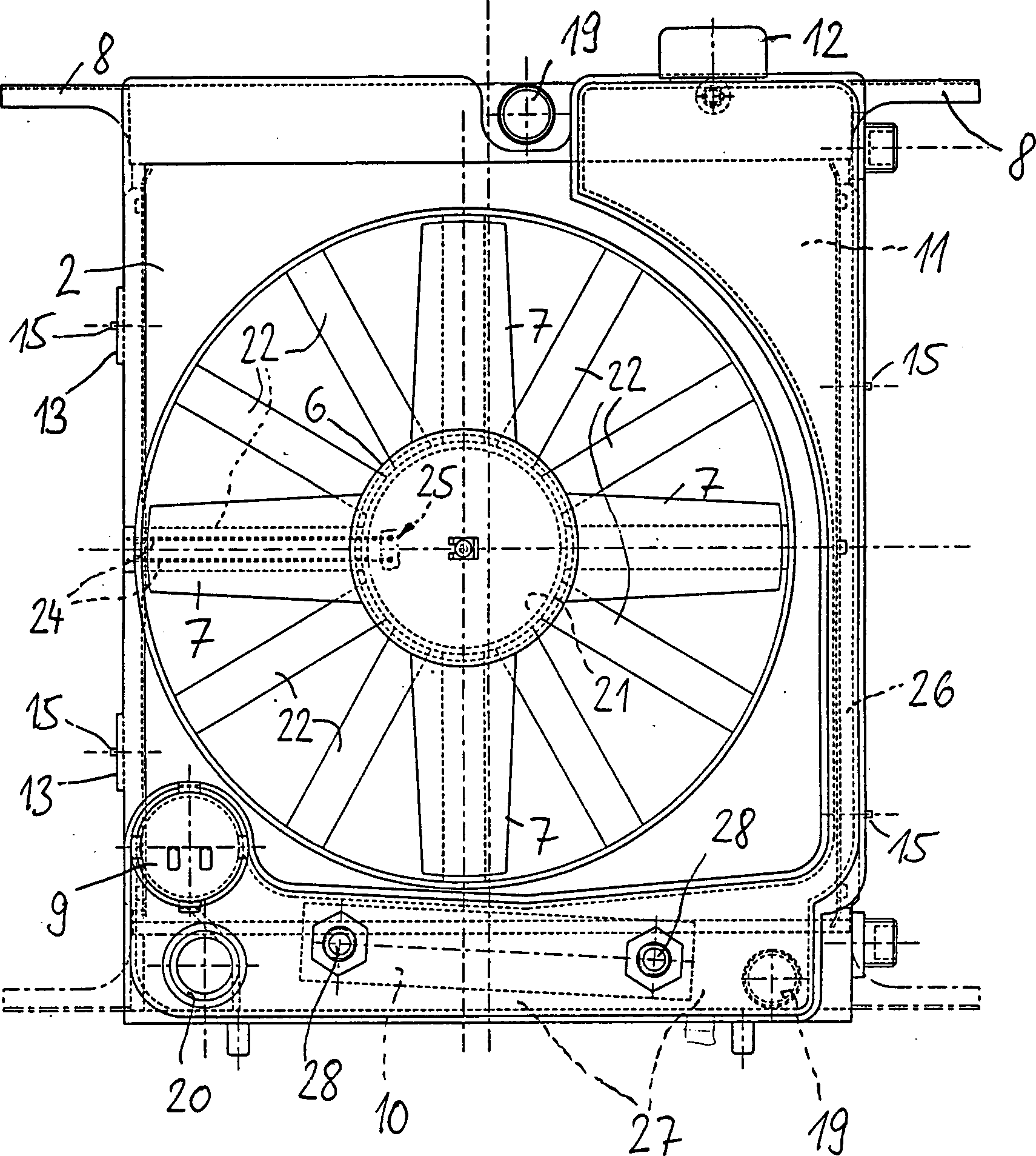
Lüfterhaube für eine Wärmeübertrageranordnung eines Kraftfahrzeugs, insbesondere eines Personenkraftwagens, dadurch gekennzeichnet, dass die Lüfterhaube (2, 2a) als einstückiges Schalenbauteil gestaltet ist, in dem wenigstens eine Hohlkammer (11, 27, 31) für die Aufnahme einer Flüssigkeit vorgesehen ist, wobei in der wenigstens einen Hohlkammer (27) wenigstens ein Wärmeübertrager, insbesondere ein Ölkühler (10), positioniert ist, dessen Zu- und Rücklaufstutzen (28) durch eine Wandung der Hohlkammer (27) zur Außenseite des Schalenbauteiles hindurchgeführt und an dieser Wandung gesichert sind.Fan cowl for a heat exchanger arrangement of a motor vehicle, in particular a passenger car, characterized in that the fan cowl (2, 2a) is designed as a one-piece shell member, in which at least one hollow chamber (11, 27, 31) is provided for receiving a liquid, wherein the at least one hollow chamber (27) at least one heat exchanger, in particular an oil cooler (10) is positioned, the supply and return pipe (28) through a wall of the hollow chamber (27) passed to the outside of the shell component and secured to this wall.
Description
Die Erfindung betrifft eine Lüfterhaube für eine Wärmeübertrageranordnung eines Kraftfahrzeugs, insbesondere eines Personenkraftwagens.The The invention relates to a fan cowl for one The heat exchanger a motor vehicle, in particular a passenger car.
Lüfterhauben für Wärmeübertrageranordnungen von Personenkraftwagen sind allgemein bekannt. Eine solche Lüfterhaube, die auch als Lüfterzarge bezeichnet wird, trägt einen Lüfter, der je nach Ausführung des Lüfters vor oder hinter der Wärmeübertrageranordnung positioniert ist. Die Wärmeübertrageranordnung besteht üblicherweise aus einem Kühlmittel/Luftkühler sowie wenigstens einem Ölkühler und bei Ausführung des Personenkraftwagens mit Klimaanlage zusätzlich aus einem Kondensator. Der Kühlmittel/Luftkühler und der Kondensator sind in Luftdurchströmungsrichtung hintereinander angeordnet. Der Kühlmittel/Luftkühler ist. Teil eines Kühlmittelkreislaufes, dem ein Ausgleichsbehälter zugeordnet ist. Ölkühler können seitlich am Kühlmittel/Luftkühler angebracht oder auch in einem Kühlmittelkasten des Kühlmittel/Luftkühlers integriert sein. Dem Kühlmittelkreislauf ist üblicherweise wenigstens eine Förderpumpe zugeordnet.fan cowls for heat exchanger arrangements Passenger cars are well known. Such a fan cover, which also as fan cowl is called carries a fan, depending on the version of the fan in front of or behind the heat exchanger arrangement is positioned. The heat exchanger arrangement usually exists from a coolant / air cooler as well at least one oil cooler and at execution of the passenger car with air conditioning additionally from a condenser. The coolant / air cooler and the condenser are in the air flow direction one behind the other arranged. The coolant / air cooler is. Part of a coolant circuit, an equalization tank assigned. Oil cooler can be side attached to the coolant / air cooler or in a coolant box the coolant / air cooler integrated be. The coolant circuit is usually at least one pump assigned.
Aus
der
Aufgabe der Erfindung ist es, eine Lüfterhaube der eingangs genannten Art zu schaffen, die gegenüber bekannten Lüfterhauben eine verbesserte Funktionalität aufweist.task The invention is a fan cover to create the aforementioned type, compared to known fan cowls an improved functionality having.
Diese Aufgabe wird bei einem Ausführungsbeispiel der Erfindung dadurch gelöst, daß die Lüfterhaube als einstückiges Schalenbauteil gestaltet ist, in dem wenigstens eine Hohlkammer für die Aufnahme einer Flüssigkeit vorgesehen ist. wobei in der wenigstens einen Hohlkammer wenigstens ein Wärmeübertrager, insbesondere ein Ölkühler, positioniert ist, dessen Zu- und Rücklaufstutzen durch eine Wandung der Hohlkammer zur Außenseite des Schalenbauteiles hindurchgeführt und an dieser Wandung gesichert sind.These Task is in one embodiment solved by the invention that the fan cover as one piece Shell component is designed in the at least one hollow chamber for the Picking up a liquid is provided. wherein in the at least one hollow chamber at least a heat exchanger, especially an oil cooler, positioned is, its inlet and outlet nozzles through a wall of the hollow chamber to the outside of the shell component passed and are secured to this wall.
Diese obige Aufgabe wird alternativ auch dadurch gelöst, daß die Lüfterhaube als einstückiges Schalenbauteil gestaltet ist, in dem wenigstens eine Hohlkammer für die Aufnahme einer Flüssigkeit vorgesehen ist und in dem Schalenbauteil wenigstens ein Strömungskanal integriert ist, der an die Hohlkammer anschließt, wobei in dem wenigstens einen Strömungskanal wenigstens ein Wärmeübertrager, insbesondere ein Ölkühler, positioniert ist, dessen Zu- und Rücklaufstutzen durch eine Wandung des Strömungskanales zur Außenseite des Schalenbauteiles hindurchgeführt und an dieser Wandung gesichert sind.These The above object is alternatively also achieved in that the fan cowl as a one-piece shell component is designed, in which at least one hollow chamber for receiving a liquid is provided and in the shell component at least one flow channel is integrated, which adjoins the hollow chamber, wherein in the at least a flow channel at least one heat exchanger, in particular an oil cooler, positioned is, its inlet and outlet nozzles through a wall of the flow channel to the outside passed through the shell component and are secured to this wall.
Durch die Integration der wenigstens einen Hohlkammer direkt in die Lüfterhaube kann ein separater Behälter für die entsprechende Flüssigkeit entfallen. Die wenigstens eine Hohlkammer kann insbesondere als Ausgleichsbehälter für einen Wärmeübertragungsmittelkreislauf, vorzugsweise einen Kühlmittelkreislauf eines Kühlmittel/Luftkühlers, ausgestaltet sein. Es können auch mehrere Hohlkammern mit unterschiedlichen Funktionen für eine gemeinsame Flüssigkeit oder für mehrere Flüssigkeiten vorgesehen sein. Selbstverständlich ist die wenigstens eine Hohlkammer derart im Seitenbereich der Lüfterhaube positioniert, daß die Grundfunktion der Lüfterhaube zur Halterung des Lüfters nicht beeinträchtigt wird.By the integration of at least one hollow chamber directly into the fan cover can be a separate container for the corresponding liquid omitted. The at least one hollow chamber can in particular as surge tank for one Heat transfer medium circuit, preferably a coolant circuit a coolant / air cooler, designed be. It can also several hollow chambers with different functions for a common liquid or for several liquids be provided. Of course is the at least one hollow chamber in the side region of the fan cover positioned that the Basic function of the fan guard for mounting the fan is not affected.
In Ausgestaltung der Erfindung ist in dem Schalenbauteil wenigstens ein Strömungskanal integriert, der an die Hohlkammer anschließt. Dieser Strömungskanal kann bei Ausgestaltung der Hohlkammer als Ausgleichsbehälter als Rücklaufleitung gestaltet sein, die mit der Hohlkammer einerseits und dem Wärmeübertragungsmittelkreislauf andererseits in Verbindung steht. Entsprechende Schlauch- oder Rohrleitungen werden durch die Integration des Strömungskanales in das Schalenbauteil vermieden.In Embodiment of the invention is at least in the shell component a flow channel integrated, which connects to the hollow chamber. This flow channel can in embodiment of the hollow chamber as a surge tank as Return line designed be, with the hollow chamber on the one hand and the heat transfer medium circuit on the other hand. Appropriate hose or piping be through the integration of the flow channel in the shell component avoided.
In weiterer Ausgestaltung der Erfindung ist im Bereich des wenigstens einen Strömungskanales und/oder der wenigstens einen Hohlkammer wenigstens ein zur Außenseite des Schalenbauteiles offener Anschlußstutzen im Schalenbauteil integriert. Der Anschlußstutzen ist vorzugsweise an einen korrespondierenden Anschlußstutzen des anschließenden Wärmeübertragers angepaßt, so daß diese eine einfache Steckverbindung miteinander eingehen können, die nach Art einer Schnellkupplung gestaltet ist. Vorzugsweise ist wenigstens einem Anschlußstutzen eine umlaufende Dichtung zugeordnet, die neben einer Abdichtung der Steckverbindung einen zusätzlichen Form- und/oder Kraftschluß für die Steckverbindung bildet. Der wenigstens eine Anschlußstutzen im Bereich des Strömungskanales und/oder der Hohlkammer kann je nach Gestaltung des jeweils korrespondierenden Anschlußstutzens als Muffe oder Stecker ausgebildet sein.In Another embodiment of the invention is in the range of at least a flow channel and / or the at least one hollow chamber at least one to the outside of the shell component open connection piece in the shell component integrated. The connecting piece is preferably to a corresponding connecting piece the subsequent heat exchanger customized, so that this can make a simple connection with each other, the designed in the manner of a quick coupling. Preferably, at least a connecting piece one associated with circumferential seal, in addition to a sealing of the connector An additional Form and / or adhesion for the connector forms. The at least one connecting piece in the region of the flow channel and / or the hollow chamber may, depending on the design of each corresponding connecting branch be designed as a sleeve or plug.
In weiterer Ausgestaltung der Erfindung ist in dem wenigstens einen Strömungskanal und/oder der wenigstens einen Hohlkammer wenigstens ein Wärmeübertrager, insbesondere ein Ölkühler, positioniert, dessen Zu- und Rücklaufstutzen durch eine Wandung des Strömungskanales und/oder der Hohlkammer zur Außenseite des Schalenbauteiles hindurchgeführt und an dieser Wandung gesichert sind. Dadurch ergibt sich mit einfachen Mitteln eine Integration des Wärmeübertragers in der Lüfterhaube.In a further embodiment of the invention, at least one heat exchanger, in particular an oil cooler, is positioned in the at least one flow channel and / or the at least one hollow chamber, the supply and return pipe through a wall of the flow channel and / or the hollow chamber passed to the outside of the shell component and secured to this wall. This results in simple integration of the heat exchanger in the fan cover.
Das Schalenbauteil und damit die Lüfterhaube können in Kunststoffbauweise oder als Blechkonstruktion gestaltet sein. In beiden Fällen ist das Schalenbauteil einstückig ausgeführt, wobei die Lüfterhaube in Kunststoffbauweise bereits einstückig hergestellt und als Metallblechkonstruktion entweder ebenfalls einstückig hergestellt oder aus mehreren Blechteilen einstückig zusammengefügt wird. Auch in Kunststoffbauweise kann die Lüfterhaube mehrschalig ausgeführt sein, wobei die verschiedenen Schalen stoffschlüssig miteinander verbun den werden. Schließlich kann das Schalenbauteil auch in Metallguß- oder -schmiedebauweise gestaltet sein.The Shell component and thus the fan cover can be designed in plastic construction or as a sheet metal construction. In both cases the shell component is in one piece executed the fan cover in plastic construction already made in one piece and as a sheet metal construction either also in one piece made or assembled in one piece from several sheet metal parts. Even in plastic construction, the fan cowl can be executed multi-shell, wherein the different shells interconnected cohesively become. After all The shell component can also be designed in metal casting or forging design be.
In weiterer Ausgestaltung der Erfindung ist auf Höhe des Strömungskanals oder auf Höhe der Hohlkammer eine nach außen offene Halteaufnahme für ein Funktionsbauteil, insbesondere eine Förderpumpe, vorgesehen. Dadurch ist es möglich, in die Lüfterhaube ein weiteres Funktionsbauteil zu integrieren. Bei Gestaltung des Funktionsbauteiles als Förderpumpe wird eine externe, zwischen Rohr- oder Schlauchleitungen eingebundene Förderpumpe vermieden, wobei auch zusätzliche Befestigungselemente entfallen können. Auch die Förderpumpe ist mittels entsprechender Dichtungen derart in die Halteaufnahme eingesetzt, daß die Dichtheit des Strömungskanales oder der Hohlkammer erhalten bleibt.In Another embodiment of the invention is at the height of the flow channel or at the level of the hollow chamber one outwards open holding receptacle for a functional component, in particular a feed pump provided. Thereby Is it possible, in the fan cover to integrate another functional component. When designing the Functional components as a feed pump becomes an external, integrated between pipe or hose lines feed pump avoided, with additional Fasteners can be omitted. Also the delivery pump is by means of appropriate seals in the holding receptacle used that the Tightness of the flow channel or the hollow chamber is maintained.
In weiterer Ausgestaltung der Erfindung weist die Halteaufnahme stegartige Rastprofilierungen auf, mittels der das Funktionsbauteil formschlüssig in der Halteaufnahme sicherbar ist. Dadurch werden separate Befestigungselemente vermieden, wodurch sich der Montageaufwand für das Funktionsbauteil erheblich reduzieren läßt.In Another embodiment of the invention, the holding receptacle web-like Locking profiles on, by means of the functional component form-fitting in the holding receptacle is securable. This will separate the fasteners avoided, resulting in the assembly work for the functional component considerably reduce.
In weiterer Ausgestaltung der Erfindung ist wenigstens ein Anschlußstutzen für die Positionierung eines Funktionsventils ausgestaltet. Ein solches Funktionsventil kann Sicherheitsfunktionen erfüllen und insbesondere als Entlüftungsventil gestaltet sein.In Another embodiment of the invention is at least one connecting piece for the Positioning of a function valve designed. Such a function valve can fulfill security functions and especially as a vent valve be designed.
In weiterer Ausgestaltung der Erfindung sind an dem Schalenbauteil mehrere steg- oder laschenartige Befestigungselemente angeordnet, mittels derer Funktionselemente an dem Schalenbauteil festlegbar sind. Dadurch wird die Funktionalität der Lüfterhaube weiter verbessert.In Further embodiment of the invention are on the shell component several web or tab-like fasteners arranged By means of which functional elements can be fixed to the shell component are. This further improves the functionality of the fan guard.
In weiterer Ausgestaltung der Erfindung ragen von der Außenseite des Schalenbauteiles mehrere Tragelemente ab, mittels derer das Schalenbauteil fahrzeugfest positionierbar ist. Dadurch sind die Tragelemente bereits einstückig an dem Schalenbauteil angeordnet, so daß separate Tragelemente entfallen können.In further embodiment of the invention protrude from the outside of the shell component from several support elements, by means of which the Shell component is fixed to the vehicle. As a result, the support elements already in one piece arranged on the shell component, so that separate support elements omitted can.
In weiterer Ausgestaltung der Erfindung ist eine topfartige Rastaufnahme zur formschlüssigen Festlegung eines Elektromotors für einen Lüfter an dem Schalenbauteil vorgesehen. Diese topfartige Rastaufnahme ist vorzugsweise im Bereich eines Tragsternes für den Lüfter positioniert und ermöglicht eine Festlegung des Elektromotors und damit des Lüfters ohne zusätzliche Befestigungselemente. Ein Gehäuse des Elektromotors weist korrespondierende Rastprofilierungen auf, mittels der die formschlüssige Festlegung des Elektromotors an dem Schalenbauteil erzielbar ist.In Another embodiment of the invention is a pot-like locking receptacle for positive fixing an electric motor for a fan provided on the shell component. This pot-like snap-in recording is preferably positioned in the region of a support star for the fan and allows a Definition of the electric motor and thus the fan without additional Fasteners. A housing the electric motor has corresponding latching profiles, by means of the positive locking Determination of the electric motor can be achieved on the shell component.
In weiterer Ausgestaltung der Erfindung sind in dem Schalenbauteil elektrische Leitungen integriert. Die Integration kann dabei durch Einbettung zwischen zwei Schalenwandungen bei mehrschaligem Aufbau des Schalenbauteiles erfolgen. In gleicher Weise können die elektrischen Leitungen auch in entsprechend vorgeformte Nuten oder Kanäle eingelegt und in diese eingeklebt, eingeklemmt oder eingeschweißt sein.In Further embodiment of the invention are in the shell component integrated electrical lines. The integration can be through Embedding between two shell walls in multi-shell construction done the shell component. In the same way, the electrical cables also in accordance preformed grooves or channels be inserted and glued into this, clamped or welded.
In weiterer Ausgestaltung der Erfindung sind im Bereich der Rastaufnahme des Elektromotors oder anderer elektrischer Funktionsteile elektrische Steckkontakte integriert, die mit den elektrischen Leitungen verbunden sind und die mit korrespondierenden elektrischen Steckkontakten des Elektromotors oder der anderen elektrischen Funktionsteile kraftschlüssig verbindbar sind. Die Steckkontakte sind vorzugsweise derart ausgeführt, daß mit dem Einsetzen des Elektromotors oder entsprechend anderer elektrischer Funktionsteile in die zugehörigen Aufnahmen am Schalenbauteil automatisch auch eine elektrische Kontaktierung erfolgt, ohne daß zusätzliche Montageschritte vorgenommen werden. Die Steckkontakte sind somit räumlich derart im Bereich entsprechender Aufnahmen für die elektrischen Funktionsteile angeordnet, daß die korrespondierenden Steckkontakte beim Einsetzen der elektrischen Funktionsteile direkt mit den elektrischen Steckkontakten des Schalenbauteiles in Eingriff gelangen.In Further embodiment of the invention are in the region of the locking receptacle the electric motor or other electrical functional parts electrical plug contacts integrated, which are connected to the electrical lines and with corresponding electrical plug contacts of the electric motor or the other electrical functional parts positively connected are. The plug contacts are preferably designed such that with the Insertion of the electric motor or according to other electrical Functional parts in the associated Shooting on the shell component automatically also an electrical contact done without additional Assembly steps are made. The plug contacts are thus spatial such in the field of appropriate recordings for the electrical functional parts arranged that the corresponding plug contacts when inserting the electrical functional parts directly with the electrical plug contacts of the shell component engage.
In weiterer Ausgestaltung der Erfindung sind zwei nebeneinanderliegende Hohlkammern in dem Schalenbauteil vorgesehen, die über einen als Rücksaugleitung gestalteten Strömungskanal miteinander in Verbindung stehen. Dabei kann die eine Hohlkammer insbesondere als Ausgleichsbehälter und die andere als Zusatzbehälter gestaltet sein, wobei der Zusatzbehälter eine Überlauffunktion übernimmt. Der Strömungskanal ist derart gestaltet, daß bei Absinken eines entsprechenden Flüssigkeitsspiegels im Ausgleichsbehälter ein Unterdruck entsteht, der im Zusatzbehälter befindliche Flüssigkeit zwangsläufig in den Ausgleichsbehälter zurücksaugt.In Another embodiment of the invention are two adjacent Hollow chambers provided in the shell member, which via a as a return line designed flow channel communicate with each other. It can be a hollow chamber especially as a surge tank and the other as additional container be designed, the additional container takes over an overflow function. The flow channel is designed so that at Falling of a corresponding liquid level in the expansion tank a negative pressure is created, the liquid in the additional container inevitably in the expansion tank back sucks.
In weiterer Ausgestaltung der Erfindung ist das Schalenbauteil mehrschalig aufgebaut. Diese Ausgestaltung ist insbesondere für die Herstellung des Schalenbauteiles in Kunststoffbauweise vorteilhaft, da unterschiedliche Halbschalen gebildet werden können, die stoffschlüssig dicht miteinander verbindbar sind. Dabei können die entsprechenden Halbschalen insbesondere miteinander verschweißt sein.In Another embodiment of the invention, the shell component is mehrschalig built up. This embodiment is particularly suitable for the production of Shell components in plastic construction advantageous because different Half shells can be formed, the cohesive are tightly interconnected. In this case, the corresponding half-shells in particular be welded together.
In weiterer Ausgestaltung der Erfindung weist das Schalenbauteil wenigstens zwei zu einer gemeinsamen Seite abragende Halteprofile auf, die wenigstens einen Wärmeübertrager seitlich außen übergreifen und die mit Rastprofilierungen zur formschlüssigen Sicherung des wenigstens einen Wärmeübertragers versehen sind. Dadurch werden vorteilhaft separate Befestigungselemente für die Halterung des wenigstens einen Wärmeübertragers vermieden. Das Vorsehen der integrierten Halteprofile an der Lüfterhaube kann auch unabhängig von dem Vorsehen einer Hohlkammer erfolgen.In further embodiment of the invention, the shell component at least two projecting to a common side holding profiles, at least a heat exchanger overlap laterally outside and with locking profiles for positive locking of at least a heat exchanger are provided. This will be advantageous separate fasteners for the Holder of the at least one heat exchanger avoided. The provision of the integrated holding profiles on the fan guard can also be independent from the provision of a hollow chamber.
In weiterer Ausgestaltung der Erfindung sind die Halteprofile wenigstens auf Höhe von Trennwänden gegenüberliegender Strömungskästen wenigstens eines Wärmeübertragers positioniert, und die Trennwände weisen über die Strömungskästen nach außen abragende Stegfortsätze auf, die formschlüssig in korrespondierenden Rastprofilierungen der Halteprofile aufnehmbar sind. Dies ist eine besonders einfache Halterung für den wenigstens einen Wärmeübertrager, wobei sich diese Ausgestaltung insbesondere bei Ausführung des Wärmeübertragers als Kondensator eignet.In Another embodiment of the invention, the retaining profiles are at least at height of partitions opposed Flow boxes at least a heat exchanger positioned, and the partitions show over the flow boxes projecting outwards Steg extensions on, the form-fitting in corresponding locking profiles of the retaining profiles can be received are. This is a particularly simple mount for the least a heat exchanger, wherein this embodiment, in particular during execution of the Heat exchanger as Capacitor is suitable.
Weitere Vorteile und Merkmale der Erfindung ergeben sich aus den Unteransprüchen sowie aus der nachfolgenden Beschreibung von bevorzugten Ausführungsbeispielen der Erfindung, die anhand der Zeichnungen dargestellt sind.Further Advantages and features of the invention will become apparent from the dependent claims and from the following description of preferred embodiments of the invention, which are illustrated by the drawings.
Eine
Wärmeübertrageranordnung
Sowohl
der Kühlmittel-Luftkühler
Die
Lüfterhaube
Um
direkt beim Einsetzen des Gehäuses
Die
Lüfterhaube
Dem
Ausgleichsbehälter
Die
Lüfterhaube
In
einem Bereich oberhalb des Austrittsstutzens
Die
Lüfterhaube
Die
Lüfterhaube
Die
Lüfterhaube
Zudem
weisen die Haltelaschen
Die
Lüfterhaube
Die
Lüfterhaube
In
den
Claims (20)
Priority Applications (1)
| Application Number | Priority Date | Filing Date | Title |
|---|---|---|---|
| DE19828362A DE19828362B4 (en) | 1998-06-25 | 1998-06-25 | Fan cover for a heat exchanger assembly of a motor vehicle |
Applications Claiming Priority (1)
| Application Number | Priority Date | Filing Date | Title |
|---|---|---|---|
| DE19828362A DE19828362B4 (en) | 1998-06-25 | 1998-06-25 | Fan cover for a heat exchanger assembly of a motor vehicle |
Publications (2)
| Publication Number | Publication Date |
|---|---|
| DE19828362A1 DE19828362A1 (en) | 1999-12-30 |
| DE19828362B4 true DE19828362B4 (en) | 2009-07-09 |
Family
ID=7872015
Family Applications (1)
| Application Number | Title | Priority Date | Filing Date |
|---|---|---|---|
| DE19828362A Expired - Fee Related DE19828362B4 (en) | 1998-06-25 | 1998-06-25 | Fan cover for a heat exchanger assembly of a motor vehicle |
Country Status (1)
| Country | Link |
|---|---|
| DE (1) | DE19828362B4 (en) |
Families Citing this family (12)
| Publication number | Priority date | Publication date | Assignee | Title |
|---|---|---|---|---|
| DE19916475A1 (en) * | 1999-04-13 | 2000-10-19 | Behr Gmbh & Co | Heat transfer unit for a motor vehicle |
| FR2807728B1 (en) * | 2000-04-17 | 2002-08-02 | Ecia Equip Composants Ind Auto | FRONT PANEL FOR A MOTOR VEHICLE INCLUDING MEANS OF MOUNTING BY SNAP-ON OF EQUIPMENT |
| DE10041794A1 (en) * | 2000-09-16 | 2002-03-07 | Modine Mfg Co | Cooling assembly, with a number of chill units, has a connection near the end of the leading and/or final flat tube for the inflow/outflow channels, to give a more compact structure |
| DE10126720B4 (en) * | 2001-05-31 | 2016-09-15 | Volkswagen Ag | Fastening arrangement for an air duct on a radiator of a motor vehicle |
| DE10322211A1 (en) * | 2003-05-16 | 2004-12-02 | Modine Manufacturing Co., Racine | heat exchanger block |
| DE10348699A1 (en) * | 2003-10-16 | 2005-05-12 | Behr Gmbh & Co Kg | Coolant radiator of a motor vehicle |
| DE102004034733A1 (en) * | 2004-07-17 | 2006-02-16 | Siemens Ag | Radiator frame with at least one electrically driven fan |
| FR2890008B1 (en) * | 2005-08-31 | 2007-10-05 | Valeo Systemes Thermiques | FAST ASSEMBLY FAN ASSEMBLY, ESPECIALLY FOR MOTOR VEHICLES |
| DE102005046796A1 (en) * | 2005-09-30 | 2007-04-05 | Behr Gmbh & Co. Kg | Arrangement for fastening of heat exchangers, has fan frame which is designed as carrier for heat exchangers e.g. module carrier of entire cooling module |
| DE102008026200B4 (en) * | 2008-05-30 | 2012-02-16 | Hydac Ag | Fluid Cooler |
| FR2965297B1 (en) * | 2010-09-28 | 2015-12-04 | Valeo Systemes Thermiques | AN OBLIGATION FOR A MOTOR VEHICLE NOZZLE AND A PUMP |
| DE102021121171A1 (en) | 2021-08-15 | 2023-02-16 | Volkswagen Aktiengesellschaft | Radiator scoop for a motor vehicle and method for its manufacture |
Citations (15)
| Publication number | Priority date | Publication date | Assignee | Title |
|---|---|---|---|---|
| US4441463A (en) * | 1982-03-20 | 1984-04-10 | Ford Motor Company | Container for fluids for operating functions in motor vehicles |
| GB2130304A (en) * | 1982-11-03 | 1984-05-31 | Unipart Group Ltd | Cowl assembly for automobile radiator fan |
| JPS6394019A (en) * | 1986-10-07 | 1988-04-25 | Nippon Denso Co Ltd | Fan shroud |
| DE2754897C2 (en) * | 1976-12-13 | 1989-04-20 | Societe Anonyme Francaise Du Ferodo, Paris, Fr | |
| EP0321330A1 (en) * | 1987-12-16 | 1989-06-21 | Automobiles Peugeot | Cowl for vehicles |
| DE3826781A1 (en) * | 1988-08-06 | 1990-02-08 | Opel Adam Ag | FRONT CROSSBAR |
| DE3841536C2 (en) * | 1988-12-09 | 1991-01-24 | Audi Ag, 8070 Ingolstadt, De | |
| US5219016A (en) * | 1992-06-15 | 1993-06-15 | General Motors Corporation | Radiator, condenser and fan shroud assembly |
| DE19526286A1 (en) * | 1995-07-19 | 1997-01-23 | Behr Gmbh & Co | Heat exchanger |
| US5649587A (en) * | 1996-02-23 | 1997-07-22 | Mccord Winn Textron, Inc. | Fan shroud and receptacle arrangement |
| DE69402396T2 (en) * | 1993-11-05 | 1997-08-07 | Ecia Equip Composants Ind Auto | Front for vehicle with internal combustion engine |
| US5660149A (en) * | 1995-12-21 | 1997-08-26 | Siemens Electric Limited | Total cooling assembly for I.C. engine-powered vehicles |
| DE19612679A1 (en) * | 1996-03-29 | 1997-10-09 | Temic Auto Electr Motors Gmbh | Motor vehicle radiator fan |
| DE19520870C2 (en) * | 1995-06-08 | 1998-03-19 | Bosch Gmbh Robert | Front module carrier of a body of a motor vehicle |
| DE69503103T2 (en) * | 1994-10-17 | 1998-11-05 | Valeo Thermique Moteur Sa | Method for attaching an air supply to a cooling radiator |
-
1998
- 1998-06-25 DE DE19828362A patent/DE19828362B4/en not_active Expired - Fee Related
Patent Citations (15)
| Publication number | Priority date | Publication date | Assignee | Title |
|---|---|---|---|---|
| DE2754897C2 (en) * | 1976-12-13 | 1989-04-20 | Societe Anonyme Francaise Du Ferodo, Paris, Fr | |
| US4441463A (en) * | 1982-03-20 | 1984-04-10 | Ford Motor Company | Container for fluids for operating functions in motor vehicles |
| GB2130304A (en) * | 1982-11-03 | 1984-05-31 | Unipart Group Ltd | Cowl assembly for automobile radiator fan |
| JPS6394019A (en) * | 1986-10-07 | 1988-04-25 | Nippon Denso Co Ltd | Fan shroud |
| EP0321330A1 (en) * | 1987-12-16 | 1989-06-21 | Automobiles Peugeot | Cowl for vehicles |
| DE3826781A1 (en) * | 1988-08-06 | 1990-02-08 | Opel Adam Ag | FRONT CROSSBAR |
| DE3841536C2 (en) * | 1988-12-09 | 1991-01-24 | Audi Ag, 8070 Ingolstadt, De | |
| US5219016A (en) * | 1992-06-15 | 1993-06-15 | General Motors Corporation | Radiator, condenser and fan shroud assembly |
| DE69402396T2 (en) * | 1993-11-05 | 1997-08-07 | Ecia Equip Composants Ind Auto | Front for vehicle with internal combustion engine |
| DE69503103T2 (en) * | 1994-10-17 | 1998-11-05 | Valeo Thermique Moteur Sa | Method for attaching an air supply to a cooling radiator |
| DE19520870C2 (en) * | 1995-06-08 | 1998-03-19 | Bosch Gmbh Robert | Front module carrier of a body of a motor vehicle |
| DE19526286A1 (en) * | 1995-07-19 | 1997-01-23 | Behr Gmbh & Co | Heat exchanger |
| US5660149A (en) * | 1995-12-21 | 1997-08-26 | Siemens Electric Limited | Total cooling assembly for I.C. engine-powered vehicles |
| US5649587A (en) * | 1996-02-23 | 1997-07-22 | Mccord Winn Textron, Inc. | Fan shroud and receptacle arrangement |
| DE19612679A1 (en) * | 1996-03-29 | 1997-10-09 | Temic Auto Electr Motors Gmbh | Motor vehicle radiator fan |
Non-Patent Citations (2)
| Title |
|---|
| JP 63094019 A.,In: Patents Abstracts of Japan, M-738,Sep. 8,1988,Vol.12,No.332 * |
| JP 63-94019 A.,In: Patents Abstracts of Japan, M-738,Sep. 8,1988,Vol.12,No.332 |
Also Published As
| Publication number | Publication date |
|---|---|
| DE19828362A1 (en) | 1999-12-30 |
Similar Documents
| Publication | Publication Date | Title |
|---|---|---|
| DE19828362B4 (en) | Fan cover for a heat exchanger assembly of a motor vehicle | |
| EP2044304B1 (en) | Heat exchanger with coupling connection, for example charge air cooler, and coupling connection for heat exchanger | |
| EP0338394B1 (en) | Electric motor especially for powering the windscreen wipper of a motor vehicle | |
| DE102004058724B4 (en) | Heat exchanger and cooling module with this | |
| DE69915764T2 (en) | Fan housing and air inlet assembly | |
| DE4142023C2 (en) | Heat exchanger unit for motor vehicles | |
| EP1910119B1 (en) | Fastening and joining element for heat exchangers, and heat exchanger assembly in a motor vehicle | |
| DE10102877B4 (en) | Front vehicle end wall | |
| EP0444423B1 (en) | Plastic header box for heat exchanger | |
| DE2523545A1 (en) | HEAT EXCHANGER FOR A MOTOR VEHICLE | |
| WO1996023179A1 (en) | Vehicle heater | |
| DE102005018560B4 (en) | pipe connection | |
| EP0864840A2 (en) | Heat exchanger for automotive vehicle | |
| DE102020109071B4 (en) | Integration component, temperature control system and motor vehicle | |
| EP0855304B1 (en) | Cooling module | |
| DE19722099A1 (en) | Heat exchanger for a motor vehicle | |
| WO2018215237A1 (en) | Heat transfer element, temperature-control device, and battery housing having at least one heat transfer element | |
| DE102012020861A1 (en) | Drain device for discharging liquid from the water tank of a motor vehicle | |
| EP3480039A1 (en) | Housing for a heating and/or air conditioning device and such a device for vehicles | |
| WO2005038379A1 (en) | Arrangement used to secure a fan frame | |
| DE19605909B4 (en) | Heat exchanger | |
| EP0307803B1 (en) | Motor car radiator with lateral parts | |
| EP1522810A2 (en) | Heat exchanger for automotive vehicle, more particularly air-cooled radiator for coolant | |
| DE19702440A1 (en) | Fuel cooler for diesel engine | |
| DE4222837C2 (en) | Arrangement of a capacitor in a vehicle |
Legal Events
| Date | Code | Title | Description |
|---|---|---|---|
| OM8 | Search report available as to paragraph 43 lit. 1 sentence 1 patent law | ||
| 8110 | Request for examination paragraph 44 | ||
| 8364 | No opposition during term of opposition | ||
| 8339 | Ceased/non-payment of the annual fee |