DE10393165B4 - Fuel cell stack and operating method - Google Patents

Fuel cell stack and operating method Download PDF

Info

Publication number
DE10393165B4
DE10393165B4 DE10393165T DE10393165T DE10393165B4 DE 10393165 B4 DE10393165 B4 DE 10393165B4 DE 10393165 T DE10393165 T DE 10393165T DE 10393165 T DE10393165 T DE 10393165T DE 10393165 B4 DE10393165 B4 DE 10393165B4
Authority
DE
Germany
Prior art keywords
segment
stack
gas passages
fuel cell
fuel cells
Prior art date
Legal status (The legal status is an assumption and is not a legal conclusion. Google has not performed a legal analysis and makes no representation as to the accuracy of the status listed.)
Expired - Lifetime
Application number
DE10393165T
Other languages
German (de)
Other versions
DE10393165T5 (en
Inventor
Pinkhas A. Rapaport
Jeffrey A. Rock
Andrew D. Bosco
John P. Salvador
Hubert Gasteiger
Lesley Paine
Current Assignee (The listed assignees may be inaccurate. Google has not performed a legal analysis and makes no representation or warranty as to the accuracy of the list.)
Motors Liquidation Co
Original Assignee
Motors Liquidation Co
Priority date (The priority date is an assumption and is not a legal conclusion. Google has not performed a legal analysis and makes no representation as to the accuracy of the date listed.)
Filing date
Publication date
Application filed by Motors Liquidation Co filed Critical Motors Liquidation Co
Publication of DE10393165T5 publication Critical patent/DE10393165T5/en
Application granted granted Critical
Publication of DE10393165B4 publication Critical patent/DE10393165B4/en
Anticipated expiration legal-status Critical
Expired - Lifetime legal-status Critical Current

Links

Images

Classifications

    • HELECTRICITY
    • H01ELECTRIC ELEMENTS
    • H01MPROCESSES OR MEANS, e.g. BATTERIES, FOR THE DIRECT CONVERSION OF CHEMICAL ENERGY INTO ELECTRICAL ENERGY
    • H01M8/00Fuel cells; Manufacture thereof
    • H01M8/02Details
    • H01M8/0202Collectors; Separators, e.g. bipolar separators; Interconnectors
    • H01M8/0258Collectors; Separators, e.g. bipolar separators; Interconnectors characterised by the configuration of channels, e.g. by the flow field of the reactant or coolant
    • H01M8/0263Collectors; Separators, e.g. bipolar separators; Interconnectors characterised by the configuration of channels, e.g. by the flow field of the reactant or coolant having meandering or serpentine paths
    • HELECTRICITY
    • H01ELECTRIC ELEMENTS
    • H01MPROCESSES OR MEANS, e.g. BATTERIES, FOR THE DIRECT CONVERSION OF CHEMICAL ENERGY INTO ELECTRICAL ENERGY
    • H01M8/00Fuel cells; Manufacture thereof
    • H01M8/02Details
    • H01M8/0202Collectors; Separators, e.g. bipolar separators; Interconnectors
    • H01M8/0258Collectors; Separators, e.g. bipolar separators; Interconnectors characterised by the configuration of channels, e.g. by the flow field of the reactant or coolant
    • H01M8/0265Collectors; Separators, e.g. bipolar separators; Interconnectors characterised by the configuration of channels, e.g. by the flow field of the reactant or coolant the reactant or coolant channels having varying cross sections
    • HELECTRICITY
    • H01ELECTRIC ELEMENTS
    • H01MPROCESSES OR MEANS, e.g. BATTERIES, FOR THE DIRECT CONVERSION OF CHEMICAL ENERGY INTO ELECTRICAL ENERGY
    • H01M8/00Fuel cells; Manufacture thereof
    • H01M8/02Details
    • H01M8/0202Collectors; Separators, e.g. bipolar separators; Interconnectors
    • H01M8/0267Collectors; Separators, e.g. bipolar separators; Interconnectors having heating or cooling means, e.g. heaters or coolant flow channels
    • HELECTRICITY
    • H01ELECTRIC ELEMENTS
    • H01MPROCESSES OR MEANS, e.g. BATTERIES, FOR THE DIRECT CONVERSION OF CHEMICAL ENERGY INTO ELECTRICAL ENERGY
    • H01M8/00Fuel cells; Manufacture thereof
    • H01M8/04Auxiliary arrangements, e.g. for control of pressure or for circulation of fluids
    • H01M8/04082Arrangements for control of reactant parameters, e.g. pressure or concentration
    • H01M8/04089Arrangements for control of reactant parameters, e.g. pressure or concentration of gaseous reactants
    • H01M8/04119Arrangements for control of reactant parameters, e.g. pressure or concentration of gaseous reactants with simultaneous supply or evacuation of electrolyte; Humidifying or dehumidifying
    • H01M8/04156Arrangements for control of reactant parameters, e.g. pressure or concentration of gaseous reactants with simultaneous supply or evacuation of electrolyte; Humidifying or dehumidifying with product water removal
    • HELECTRICITY
    • H01ELECTRIC ELEMENTS
    • H01MPROCESSES OR MEANS, e.g. BATTERIES, FOR THE DIRECT CONVERSION OF CHEMICAL ENERGY INTO ELECTRICAL ENERGY
    • H01M8/00Fuel cells; Manufacture thereof
    • H01M8/24Grouping of fuel cells, e.g. stacking of fuel cells
    • H01M8/241Grouping of fuel cells, e.g. stacking of fuel cells with solid or matrix-supported electrolytes
    • HELECTRICITY
    • H01ELECTRIC ELEMENTS
    • H01MPROCESSES OR MEANS, e.g. BATTERIES, FOR THE DIRECT CONVERSION OF CHEMICAL ENERGY INTO ELECTRICAL ENERGY
    • H01M8/00Fuel cells; Manufacture thereof
    • H01M8/24Grouping of fuel cells, e.g. stacking of fuel cells
    • H01M8/249Grouping of fuel cells, e.g. stacking of fuel cells comprising two or more groupings of fuel cells, e.g. modular assemblies
    • YGENERAL TAGGING OF NEW TECHNOLOGICAL DEVELOPMENTS; GENERAL TAGGING OF CROSS-SECTIONAL TECHNOLOGIES SPANNING OVER SEVERAL SECTIONS OF THE IPC; TECHNICAL SUBJECTS COVERED BY FORMER USPC CROSS-REFERENCE ART COLLECTIONS [XRACs] AND DIGESTS
    • Y02TECHNOLOGIES OR APPLICATIONS FOR MITIGATION OR ADAPTATION AGAINST CLIMATE CHANGE
    • Y02EREDUCTION OF GREENHOUSE GAS [GHG] EMISSIONS, RELATED TO ENERGY GENERATION, TRANSMISSION OR DISTRIBUTION
    • Y02E60/00Enabling technologies; Technologies with a potential or indirect contribution to GHG emissions mitigation
    • Y02E60/30Hydrogen technology
    • Y02E60/50Fuel cells

Abstract

Brennstoffzellenstapel mit: einer Vielzahl von Brennstoffzellen (40, 50), die in zumindest zwei Brennstoffzellensegmente (34, 36; 70, 72) unterteilt sind, von denen jedes einen Anteil der Vielzahl von Brennstoffzellen (40, 50), die darin angeordnet sind, aufweist, und die als aufeinander folgende oberstromige und unterstromige Paare von Segmenten (34, 36; 70, 72) angeordnet sind; wobei jeder der Anteile der Brennstoffzellen jedes Segmentes (34, 36; 70, 72) eine Vielzahl von Reaktandengasdurchgängen aufweist, die mit einem gemeinsamen Einlassreaktandengasdurchgang (38, 48) und einem gemeinsamen Auslassreaktandengasdurchgang (42, 52) versehen sind; wobei jedes Paar von Segmenten (34, 36; 70, 72) ein Separatorsegment (44) aufweist, das zwischen dem oberstromigen Segment (34) und dem unterstromigen Segment (36) angeordnet ist, wobei das Separatorsegment (44) in Fluidverbindung mit dem gemeinsamen Auslassreaktandengasdurchgang (42) des oberstromigen Segmentes (34) und dem gemeinsamen Einlassreaktandengasdurchgang (48) des unterstromigen Segmentes (36) desselben Segmentpaares (34, 36; 70, 72) steht; wobei jeder der Vielzahl von...A fuel cell stack comprising: a plurality of fuel cells (40, 50) divided into at least two fuel cell segments (34, 36; 70, 72) each of which has a portion of the plurality of fuel cells (40, 50) disposed therein, and which are arranged as successive upstream and downstream pairs of segments (34, 36; 70, 72); each of the portions of the fuel cells of each segment (34, 36; 70, 72) having a plurality of reactant gas passages provided with a common reactant gas inlet passage (38, 48) and a reactant outlet common gas passage (42, 52); each pair of segments (34, 36; 70, 72) including a separator segment (44) disposed between the upstream segment (34) and the downstream segment (36), the separator segment (44) in fluid communication with the common Outlet reactant gas passage (42) of the upstream segment (34) and the common inlet reactant gas passage (48) of the downstream segment (36) of the same segment pair (34, 36; 70, 72); each of the multitude of ...

Description

GEBIET DER ERFINDUNGFIELD OF THE INVENTION

Die vorliegende Erfindung betrifft Brennstoffzellensysteme und insbesondere einen Brennstoffzellenstapel und ein Verfahren zum Betrieb eines Brennstoffzellenstapels.The present invention relates to fuel cell systems, and more particularly to a fuel cell stack and a method of operating a fuel cell stack.

HINTERGRUND DER ERFINDUNGBACKGROUND OF THE INVENTION

Brennstoffzellen sind bei vielen Anwendungen als eine Energie- bzw. Antriebsquelle vorgeschlagen worden, wobei Brennstoffzellen beispielsweise zur Verwendung in elektrischen Fahrzeugantriebsanlagen als Ersatz für Verbrennungsmotoren vorgeschlagen worden sind. Bei Brennstoffzellen vom Typ mit Protonenaustauschmembran (PEM) wird Wasserstoff an die Anode der Brennstoffzelle und Sauerstoff als das Oxidationsmittel an die Kathode geliefert. Eine typische PEM-Brennstoffzelle und ihre Membranelektrodenanordnung (MEA) sind in den U.S.-Patenten US 5,272,017 A und US 5,316,871 beschrieben, die am 21. Dezember 1993 bzw. 31. Mai 1994 erteilt wurden und auf die General Motors Corporation übertragen sind. Die MEAs umfassen eine dünne, protonendurchlässige, nicht elektrisch leitende Festpolymerelektrolytmembran, die auf einer ihrer Seiten den Anodenkatalysator und auf der entgegengesetzten Seite den Kathodenkatalysator umfasst.Fuel cells have been proposed as a source of power in many applications, with fuel cells being proposed, for example, for use in vehicle electrical drive systems as a replacement for internal combustion engines. In proton exchange membrane type (PEM) fuel cells, hydrogen is supplied to the anode of the fuel cell and oxygen as the oxidant to the cathode. A typical PEM fuel cell and its membrane electrode assembly (MEA) are disclosed in US patents US 5,272,017 A and US 5,316,871 issued on 21 December 1993 and 31 May 1994, respectively, and assigned to General Motors Corporation. The MEAs comprise a thin, proton transmissive, non-electrically conductive, solid polymer electrolyte membrane that includes the anode catalyst on one side and the cathode catalyst on the opposite side.

Die nachveröffentlichte Patentschrift DE 102 43 163 B4 offenbart ein Brennstoffzellenpaket, das ein Paket von Unterpaketen mit zwischen diesen angeordneten Zwischenplatten aufweist. Jedes der Unterpakete weist ein Paket aus Membranelektrodenanordnungen mit zwischen diesen angeordneten Separatoren auf, von denen jede eine Anode, eine Kathode und eine Ionenaustauschmembran umfasst, welche zwischen der Anode und der Kathode sandwichartig angeordnet ist. Jede der Zwischenplatten weist einen Verbindungsdurchgang zur Verbindung eines Reaktionsgasauslass-Verbindungsdurchgangs eines stromaufwärtigen Unterpakets bezüglich einer Richtung, in welcher ein Reaktionsgas geführt wird, und eines Reaktionsgaseinlass-Verbindungsdurchgangs eines stromabwärtigen Unterpakets bezüglich dieser Richtung auf.The post-published patent DE 102 43 163 B4 discloses a fuel cell package having a package of sub-packages with intermediate plates disposed therebetween. Each of the subpackets comprises a package of membrane electrode assemblies having separators therebetween, each comprising an anode, a cathode, and an ion exchange membrane sandwiched between the anode and the cathode. Each of the intermediate plates has a communication passage for connecting a reaction gas outlet communication passage of an upstream sub-packet with respect to a direction in which a reaction gas is guided, and a reaction gas inlet communication passage of a downstream sub-packet with respect to this direction.

Die US 5,763,113 A offenbart ferner ein Verfahren und eine Vorrichtung zur Überwachung des Leistungsverhaltens eines Brennstoffzellenpakets. Das Brennstoffzellenpaket weist eine Vielzahl von Brennstoffzellen auf, die jeweils parallel zueinander an Zuleitungen und Ableitungen für Wasserstoff und Luft angeschlossen sind.The US 5,763,113 A further discloses a method and apparatus for monitoring the performance of a fuel cell stack. The fuel cell stack has a multiplicity of fuel cells, which are each connected in parallel to supply lines and outlets for hydrogen and air.

Die US 5,478,662 A offenbart ein Brennstoffzellensystem mit mehreren hintereinander angeordneten Brennstoffzellenstapeln. Das Kathodengas weist in jedem Brennstoffzellenstapel eine unidirektionale, schwerkraftunterstützte Strömungsrichtung auf.The US 5,478,662 A discloses a fuel cell system having a plurality of fuel cell stacks arranged one behind the other. The cathode gas has a unidirectional, gravity-assisted flow direction in each fuel cell stack.

Weiterer Stand der Technik ist aus der DE 33 23 491 A1 und der DE 100 54 444 A1 bekannt.Further prior art is known from DE 33 23 491 A1 and the DE 100 54 444 A1 known.

Der Begriff ”Brennstoffzelle” wird typischerweise dazu verwendet, abhängig vom Zusammenhang entweder eine einzelne Zelle oder eine Vielzahl von Zellen (Stapel) zu bezeichnen. Zur Bildung eines Brennstoffzellenstapels wird üblicherweise eine Vielzahl einzelner Zellen miteinander gebündelt. Jede Zelle in dem Stapel umfasst eine Membranelektrodenanordnung, die ihren Spannungszuwachs liefert. Typische Anordnungen mehrerer Zellen in einem Stapel sind in dem Patent US 5,763,113 A beschrieben, das auf die General Motors Corporation übertra- gen wurde.The term "fuel cell" is typically used to refer to either a single cell or a plurality of cells (stacks), depending on the context. To form a fuel cell stack, usually a plurality of individual cells are bundled together. Each cell in the stack includes a membrane electrode assembly that provides its voltage gain. Typical arrangements of several cells in a stack are in the patent US 5,763,113 A which was transferred to General Motors Corporation.

Die elektrisch leitenden Elemente, die die MEAs schichtartig anordnen, können eine Gruppierung aus Kanälen oder Nuten in ihren Seiten umfassen, um die gasförmigen Reaktanden der Brennstoffzellen über die Oberflächen der jeweiligen Kathode und Anode zu verteilen. In dem Brennstoffzellenstapel ist eine Vielzahl von Zellen in elektrischer Reihe aneinander gestapelt, während sie voneinander durch eine gasundurchlässige, elektrisch leitende bipolare Platte getrennt sind. Bei einer üblichen Konstruktion mit einzelnem Durchgang werden die Reaktanden an die Brennstoffzellen durch einzelne Einlassverteiler und -sammelleitungen geliefert. Von einem Einlassverteiler, der eine Strömung an eine Einlasssammelleitung vorsieht, wird der Reaktand, beispielsweise die Anodenströmung, in eine Vielzahl von Strömungspfaden unterteilt, die einzelne Zellen speisen. Der gesamte Reaktand (in diesem Fall die Anodenströmung) verlässt als Abgas die einzelnen Zellen, mischt sich in der Auslasssammelleitung und verlässt den Stapel durch den Auslassverteiler. Bei der Konstruktion mit einzelnem Durchgang besitzen die Anodenseiten aller Zellen dieselbe Einlasswasserstoffkonzentration.The electrically conductive elements laminating the MEAs may include an array of channels or grooves in their sides to distribute the gaseous reactants of the fuel cells across the surfaces of the respective cathode and anode. In the fuel cell stack, a plurality of cells are stacked in electrical series while being separated from each other by a gas impermeable, electrically conductive bipolar plate. In a typical single pass design, the reactants are delivered to the fuel cells through individual inlet manifolds and manifolds. From an inlet manifold that provides flow to an inlet header, the reactant, such as the anode flow, is divided into a plurality of flow paths that feed individual cells. The entire reactant (in this case the anode stream) exits the individual cells as exhaust gas, mixes in the exhaust manifold, and leaves the stack through the exhaust manifold. In the single pass design, the anode sides of all cells have the same inlet hydrogen concentration.

Der Nachteil der Konstruktion mit einzelnem Durchgang zum Führen von Reaktandengas besteht darin, dass der Brennstoffzellenstapel nicht in der Lage ist, bei niedriger Stöchiometrie stabil zu arbeiten, d. h. nahe des Massendurchflusses von Reaktanden, der erforderlich ist, um eine gegebene Leistungsabgabe zu erfüllen. Es ist daher schwierig, eine wirksame Wasserstoff- oder Sauerstoffverwendung zu erreichen. Aufgrund dessen ist der Systemwirkungsgrad nicht optimal.The disadvantage of the single pass design for guiding reactant gas is that the fuel cell stack is unable to work stably at low stoichiometry, i. H. near the mass flow of reactants required to meet a given power output. It is therefore difficult to achieve effective hydrogen or oxygen utilization. Because of this, the system efficiency is not optimal.

Stapelkonstruktionen, die die obige Situation teilweise korrigieren, sind bekannt, wie beispielsweise die Stapelkonstruktion des Patentes US 5,478,662 A , die auf Strasser erteilt ist. Bei Stapeln, wie bei- spielsweise der Strasser-Konstruktion, sind einzelne Gruppen paralleler Zellen angeordnet, wobei die Strömung in jeder Zelle jeder Gruppe parallel ist und die gesamte Strömung von jeder Gruppe zwischen Gruppen in Reihe strömt. Bei einer beispielhaften Stapelkonstruktion besitzt jede Stapelgruppe einen Einlass- und einen Auslassverteiler, und jeder Auslassverteiler hat Abläufe, um Wasser zu sammeln, das als ein Reaktionsprodukt gebildet wird. Wenn das Wasser nicht abgelassen wird, baut es sich in nachfolgenden Zellengruppen auf. Die Anzahl einzelner Brennstoffzellen variiert normalerweise bei diesen Stapelkonstruktionen, wobei die anfänglichen oder oberstromigen Segmente der Zellen die größte Anzahl einzelner Brennstoffzellen umfassen und jedes nachfolgende Segment eine verringerte Menge von Brennstoffzellen vorsieht. Bei diesem Ausgestaltungstyp besitzt das letzte Segment in dem Satz von Segmenten normalerweise die geringste Anzahl einzelner Brennstoffzellen.Stack constructions that partially correct the above situation are known, such as the stack construction of the patent US 5,478,662 A issued on Strasser. In stacks, such as the Strasser design, individual groups of parallel cells are arranged, with the flow in each cell of each group being parallel and the total flow of each group flowing between groups in series. In an exemplary stack construction, each stack group has an inlet and an outlet manifold, and each outlet manifold has drains to collect water formed as a reaction product. If the water is not drained, it builds up in subsequent cell groups. The number of individual fuel cells normally varies in these stacked constructions, with the initial or upstream segments of the cells comprising the largest number of individual fuel cells and each subsequent segment providing a reduced amount of fuel cells. In this embodiment type, the last segment in the set of segments normally has the least number of individual fuel cells.

Ein Nachteil gemeinsam gruppierter Stapelkonstruktionen entsteht dann, wenn Reaktandengase als Reformat inerte Komponenten besitzen, die durch den Stapel strömen. Der Inertgasanteil des Reformat-Brennstoffes, der durch jede Gruppe des Stapels hindurch beibehalten wird, konzentriert sich, wenn die Menge an Brennstoffzellen in jedem Segment abnimmt, und kann zur Folge haben, dass das letzte Stapelsegment den Gesamtdruckabfall durch den Stapel kontrolliert. Normalerweise umfasst ein Wasserstoffreformatstrom, der in einen Brennstoffzellenstapel eintritt, ungefähr 40 Vol.-% Wasserstoff. Das verbleibende Volumen umfasst Stickstoff und andere Gase. Es wird nur der Wasserstoff von dem Brennstoffzellenstapel verbraucht (Bildung von Wasser), wodurch 60% des Anodengasvolumens als Inertgas durch jede Gruppe des Stapels strömen. Dieses Volumen an Inertgas bestimmt den Druckabfall über die kleinsten Gruppen des Stapels. Wenn Luft als das Kathodengas verwendet wird, umfasst die Sauerstoffkonzentration normalerweise zwischen 20 bis 40 Vol.-% der Strömung. Das verbleibende Volumen von etwa 60 bis 80 Vol.-% der Kathodenströmung umfasst Stickstoff mit anderen Inertgasen.A disadvantage of co-grouped stacked constructions arises when reactant gases have reformate inert components that flow through the stack. The inert gas portion of the reformate fuel that is maintained throughout each group of the stack concentrates as the amount of fuel cells in each segment decreases, and may result in the last stack segment controlling the total pressure drop across the stack. Normally, a hydrogen reformate stream entering a fuel cell stack will comprise about 40% hydrogen by volume. The remaining volume includes nitrogen and other gases. Only the hydrogen from the fuel cell stack is consumed (formation of water), whereby 60% of the anode gas volume flows as an inert gas through each group of the stack. This volume of inert gas determines the pressure drop across the smallest groups in the stack. When air is used as the cathode gas, the oxygen concentration normally comprises between 20 to 40 vol% of the flow. The remaining volume of about 60 to 80% by volume of the cathode stream comprises nitrogen with other inert gases.

Die obigen Reihen-/Parallelstapelkonstruktionen sehen normalerweise ein serpentinenartiges Strömungsmuster durch den Stapel hindurch vor. Ein serpentinenartiger Strömungspfad resultiert sowohl in anoden- als auch kathodenseitigen Reaktandenströmungen, die entweder horizontal durch den Stapel verlaufen oder die für eines oder mehrere einzelne Segmente die Schwerkraft überwinden müssen. Ein Wasseraufbau in den Brennstoffzellen verhindert einen Reaktandenkontakt mit den Katalysatormaterialien der Brennstoffzellen, wodurch der Stapelwirkungsgrad verringert wird. Wasser, das in den nicht schwerkraftunterstützten Gruppen erzeugt wird, muss durch die Zellen mit dem Reaktandengas gedrängt werden oder es muss zugelassen werden, dass dieses gegen die Reaktandenströmungsrichtung zur Entfernung von dem Stapel ”rückfließen” kann, wodurch der Wirkungsgrad des Stapels verringert wird.The above series / parallel stack designs normally provide a serpentine flow pattern through the stack. A serpentine flow path results in both anode and cathode side reactant flows that either pass horizontally through the stack or that must overcome gravity for one or more individual segments. Water buildup in the fuel cells prevents reactant contact with the catalyst materials of the fuel cells, thereby reducing stack efficiency. Water generated in the non-gravity assisted groups must be forced through the cells with the reactant gas, or allowed to "flow back" against the reactant flow direction for removal from the stack, thereby reducing the efficiency of the stack.

ZUSAMMENFASSUNG DER ERFINDUNGSUMMARY OF THE INVENTION

Die obigen Nachteile für Brennstoffzellenstapel werden durch eine Stapelkonstruktion der vorliegenden Erfindung gelöst. Die Stapelkonstruktion der vorliegenden Erfindung umfasst einzelne Segmente von Brennstoffzellenelementen, die in gleichwertigen oder verschiedenen Mengen von Brennstoffzellenelementen in jedem Segment angeordnet sind. Jedes Segment ist derart ausgebildet, dass es eine Strömung in jeder Brennstoffzelle in einer schwerkraftunterstützten Richtung vorsieht. Diese Anordnung steigert die Stabilität des Brennstoffzellenstapelbetriebs, indem zugelassen wird, dass das gesamte Volumen entweder der anodenseitigen oder kathodenseitigen oder beiden Strömungen durch die Segmente des Stapels verteilt wird, in dem nur ein Anteil der Gesamtzahl der Zellen vorhanden ist.The above disadvantages for fuel cell stacks are solved by a stack construction of the present invention. The stack construction of the present invention includes individual segments of fuel cell elements arranged in equivalent or different amounts of fuel cell elements in each segment. Each segment is configured to provide a flow in each fuel cell in a gravity assisted direction. This arrangement increases the stability of the fuel cell stack operation by allowing the entire volume of either the anode-side or cathode-side or both streams to be distributed through the segments of the stack where only a fraction of the total number of cells is present.

Bei einer bevorzugten Ausführungsform reichert ein erstes Segment, das normalerweise den größten Prozentsatz von Stapelbrennstoffzellen umfasst, den größten Prozentsatz des in dieses Segment eintretenden Reaktanden ab. Das erste Segment ist derart ausgebildet, um eine abwärts gerichtete oder schwerkraftunterstützte Strömung durch jede Zelle vorzusehen. Der das erste Segment verlassende Reaktand wird an ein zweites Segment gerichtet, das eine kleinere Menge von darin angeordneten Brennstoffzellen aufweist, das ebenfalls angeordnet ist, um eine schwerkraftunterstützte Strömung vorzusehen. Dieses zweite Segment reagiert den Großteil des verbleibenden Brennstoffes von der Reaktandenströmung. Wenn es notwendig ist, wird ein drittes oder werden weitere Segmente von Zellen verwendet, um die Verwendung des Wasserstoffs und Sauerstoffs von den Reaktandenströmungen zu maximieren. Jedes Segment sieht parallele Brennstoffzellen vor und ist für eine schwerkraftunterstützte Strömung durch jede Zelle des Segmentes ausgebildet. Die Gesamtstöchiometrie des Stapels wird durch die Konstruktion der vorliegenden Erfindung verbessert.In a preferred embodiment, a first segment, which normally comprises the largest percentage of stack fuel cells, accumulates the largest percentage of the reactant entering this segment. The first segment is configured to provide a downward or gravity assisted flow through each cell. The reactant leaving the first segment is directed to a second segment having a smaller amount of fuel cells disposed therein which is also arranged to provide gravity assisted flow. This second segment reacts most of the remaining fuel from the reactant stream. If necessary, a third or more segments of cells are used to maximize the use of hydrogen and oxygen from the reactant streams. Each segment provides for parallel fuel cells and is designed for gravity-assisted flow through each cell of the segment. The overall stoichiometry of the stack is improved by the construction of the present invention.

Zwischen jedem Stapelsegment ist ein Separatorsegment angeordnet, wobei die gesamte Strömung, die das vorhergehende Segment verlässt, durch das Separatorsegment geführt wird. Bei einer bevorzugten Ausführungsform sind die Separatorsegmente zwischen einem Paar bipolarer Platten angeordnet, die keine Membranelektrodenanordnung (MEA) aufweisen. Der Zweck des Separatorsegments besteht darin, die gesamte Strömung von dem Auslass oder unteren Abschnitt dieses Segments in den Einlass oder oberen Abschnitt des nächsten nachfolgenden Segmentes ohne Reaktion in der Brennstoffströmung und daher ohne Erzeugung von zusätzlichem Wasser umzulenken. Jedes Separatorsegment ist ein Bauelement, das an einzelnen Segmenten von Brennstoffzellenelementen anliegt. Zwischen jedem Paar von Segmenten der Brennstoffzellen ist ein separates Separatorelement vorgesehen, um eine Strömung zwischen einzelnen Strömungsgruppen, d. h. Anode, Kathode und Kühlmittel, separat umzulenken. Die jedes Strömungssegment verlassende Strömung wird an einem unteren Abschnitt dieses Stapelsegmentes gesammelt und allgemein aufwärts zu einem oberen Einlass des nächsten nachfolgenden Segmentes umgeleitet, um eine ”kaskadenartige” Stapelkonstruktion zu bilden. Dies sieht eine Strömung durch die einzelnen Brennstoffzellensegmente nur in einer schwerkraftunterstützten Richtung, d. h. abwärts, vor.Between each stack segment a Separatorsegment is arranged, whereby the entire flow, which leaves the preceding segment, is led by the Separatorsegment. In a preferred embodiment, the separator segments are disposed between a pair of bipolar plates that do not have a membrane electrode assembly (MEA). The purpose of the separator segment is to allow all flow from the outlet or lower portion of it Segments in the inlet or upper portion of the next succeeding segment without reaction in the fuel flow and therefore divert without generating additional water. Each separator segment is a component that abuts individual segments of fuel cell elements. Between each pair of segments of the fuel cells, a separate separator element is provided to separately divert a flow between individual flow groups, ie anode, cathode and coolant. The flow leaving each flow segment is collected at a lower portion of this stack segment and diverted generally upward to an upper inlet of the next succeeding segment to form a "cascading" stack construction. This provides flow through the individual fuel cell segments only in a gravity assisted direction, ie downwards.

Wasser, das als ein Reaktionsprodukt in jedem einzelnen Segment gebildet wird, wird gemeinsam an der Basis jedes folgenden Separatorsegments abgelassen. Dieses Wasservolumen wird durch Ablassleitungen an einen Austragspunkt in dem Stapel ausgetragen. Dies stellt sicher, dass das in jedem Segment des Stapels gebildete Wasser in einer schwerkraftunterstützten Richtung zu den Schwerkraftablasspunkten an der Basis jedes Separatorelements abläuft und sieht ein effektives Entfernungsverfahren für in dem Stapel erzeugtes flüssiges Wasser vor.Water formed as a reaction product in each individual segment is vented together at the base of each subsequent separator segment. This volume of water is discharged through discharge lines to a discharge point in the stack. This ensures that the water formed in each segment of the stack drains in a gravity assisted direction to the gravity drain points at the base of each separator element and provides an effective removal method for liquid water generated in the stack.

Eine weitere Ausführungsform der vorliegenden Erfindung sieht auch eine gewählte Verwendung einer abgewandelten Stromgeometrie für die Strömung für Brennstoffzellenelemente in jedem Brennstoffzellensegment vor. Durch Abwandlung der Strömungspfadgeometrie, d. h. Erhöhung der Strömungsdurchgangsgröße oder -länge der Brennstoffzellenelemente in zumindest einem gewählten Segment können verschiedene Reformatströme aus Reaktand mit unterschiedlichen Volumenprozentsätzen an Inertgas(en) verwendet werden. Der Reformatbrennstoffstrom umfasst normalerweise ein höheres Inertgasvolumen im Vergleich zu dem Volumen des Reaktandengases, d. h. Wasserstoff. Beispielsweise umfasst ein geeigneter Reformatbrennstoffstrom anfänglich etwa 40 Vol.-% Wasserstoff und etwa 60 Vol.-% Inertgas. Wenn der Strom den Stapel durchquert und Wasserstoff reagiert, um Wasser zu bilden, läuft das Wasser ab, wodurch ein erhöhtes Volumen an Inertgas in dem Strom zurückbleibt. Es ist daher erwünscht, die Anzahl von Brennstoffzellen in aufeinander folgenden Segmenten auf Grundlage des sich verringernden Wasserstoffvolumens zu verringern. Eine Verringerung der Brennstoffzellenmenge, während die Brennstoffzellengröße beibehalten wird, kann einen erhöhten Druckabfall in dem unterstromigen Segment bewirken, wodurch die Strömung des Brennstoffstroms durch den Stapel gesteuert oder begrenzt wird. Durch Erhöhung des Brennstoffzellenquerschnitts in einem oder mehreren gewählten unterstromigen Segmenten erhöht sich der Druckabfall nicht, wenn die Anzahl von Zellen abnimmt. Das Ergebnis ist ein erhöhter Wirkungsgrad bei verringerten Kosten, da weniger Brennstoffzellen verwendet werden, während die Nettoströmungsrate beibehalten wird. Das Inertgas, das nicht von dem Brennstoffzellenstapel reagiert wird, steuert daher nicht den Gesamtdruckabfall über den Stapel.Another embodiment of the present invention also contemplates selected use of modified flow stream geometry for fuel cell elements in each fuel cell segment. By modifying the flow path geometry, i. H. Increasing the flow passage size or length of the fuel cell elements in at least one selected segment, various reactant reformate streams having different volume percent inert gas (s) may be used. The reformate fuel stream normally comprises a higher inert gas volume compared to the volume of the reactant gas, i. H. Hydrogen. For example, a suitable reformate fuel stream initially comprises about 40% by volume of hydrogen and about 60% by volume of inert gas. As the stream traverses the stack and hydrogen reacts to form water, the water drains, leaving an increased volume of inert gas in the stream. It is therefore desirable to reduce the number of fuel cells in successive segments based on the decreasing volume of hydrogen. Reducing the fuel cell amount while maintaining the fuel cell size may cause an increased pressure drop in the downstream segment, thereby controlling or limiting the flow of fuel flow through the stack. By increasing the fuel cell cross-section in one or more selected downstream segments, the pressure drop does not increase as the number of cells decreases. The result is increased efficiency at a reduced cost as fewer fuel cells are used while maintaining the net flow rate. The inert gas that is not reacted by the fuel cell stack therefore does not control the total pressure drop across the stack.

Bei einer weiteren Ausführungsform der vorliegenden Erfindung ist eine Reihenströmung von Kühlmittel durch die einzelnen Segmente vorgesehen. Das Kühlmittel tritt in das Ende des Stapels ein, an dem die Reaktanden in den Stapel eintreten, und folgt der Strömung des Brennstoffstroms. Der Vorteil einer Reihenströmung ist, dass Kühlmittel mit seiner niedrigsten Temperatur in den Stapel an dem Punkt eintritt, an dem das trockenste Reaktandengas in den Stapel eintritt, wodurch der maximale Temperaturabfall des Reaktandengases und daher die höchste relative Feuchte für das Einlassgas vorgesehen wird. Indem die niedrigste Temperatur für das eintretende Reaktandengas vorgesehen wird, wird sein Taupunkt verringert und erfordert sehr wenig Wasserdampferzeugung, um die gewünschten 100% relative Feuchte für die Strömung des Brennstoffstromes durch den Stapel zu erreichen. Es ist normalerweise erwünscht, etwa 100% relative Feuchte (RH) in jedem Segment des Stapels vorzusehen, da kontinuierlich Wasser erzeugt wird und überschüssiges flüssiges Wasser eine Strömung wie auch einen Wasserstoffkontakt mit den Brennstoffzellen behindert.In another embodiment of the present invention, a series flow of coolant through the individual segments is provided. The coolant enters the end of the stack where the reactants enter the stack and follows the flow of the fuel stream. The advantage of a serial flow is that coolant at its lowest temperature enters the stack at the point where the driest reactant gas enters the stack, thereby providing the maximum temperature drop of the reactant gas and therefore the highest relative humidity for the inlet gas. By providing the lowest temperature for the incoming reactant gas, its dew point is reduced and requires very little steam generation to achieve the desired 100% relative humidity for the flow of fuel flow through the stack. It is usually desirable to provide about 100% relative humidity (RH) in each segment of the stack as water is continuously generated and excess liquid water impedes flow as well as hydrogen contact with the fuel cells.

Weitere Anwendungsgebiete der vorliegenden Erfindung sind nachfolgend detaillierter beschrieben. Es sei zu verstehen, dass die detaillierte Beschreibung wie auch spezifische Beispiele, während sie die bevorzugte Ausführungsform der Erfindung darstellen, nur zu Zwecken der Veranschaulichung und nicht dazu bestimmt sind, den Schutzumfang der Erfindung zu beschränken.Further fields of application of the present invention are described in more detail below. It should be understood that the detailed description as well as specific examples, while indicating the preferred embodiment of the invention, are intended for purposes of illustration only and are not intended to limit the scope of the invention.

KURZE BESCHREIBUNG DER ZEICHNUNGENBRIEF DESCRIPTION OF THE DRAWINGS

1 ist eine perspektivische Ansicht eines einzelnen Brennstoffstroms durch einen beispielhaften Brennstoffzellenstapel mit drei Gruppen, bei dem eine serpentinenartige Strömung durch den Stapel vorgesehen ist; 1 Figure 3 is a perspective view of a single fuel stream through an exemplary three-group fuel cell stack in which a serpentine flow is provided through the stack;

2 ist ein geschnittener Aufriss eines Stromes einer einzelnen Strömung durch einen beispielhaften Brennstoffzellenstapel mit zwei Segmenten gemäß den Grundsätzen der vorliegenden Erfindung. 2 FIG. 5 is a cutaway elevational view of a single flow stream through an exemplary two-segment fuel cell stack in accordance with the principles of the present invention. FIG.

3 ist ein Blockschaubild in perspektivischer Ansicht, das eine bevorzugte Ausführungsform der vorliegenden Erfindung zeigt, wobei ein größeres erstes Segment von Brennstoffzellen und ein kleineres zweites Segment von Brennstoffzellen vorgesehen sind und wobei das Separatorsegment zur Vereinfachung weggelassen wurde; 3 is a block diagram in perspective view, which is a preferred embodiment of the present invention, wherein a larger first segment of fuel cells and a smaller second segment of fuel cells are provided and wherein the separator segment has been omitted for simplicity;

4 ist eine perspektivische Ansicht auf Grundlage von 3, die ferner die Strömungspfade für einen Reformatbrennstoffzellenstapel der vorliegenden Erfindung zeigt; und 4 is a perspective view based on 3 further showing the flow paths for a reformate fuel cell stack of the present invention; and

5 ist eine teilweise geschnittene perspektivische Ansicht eines Stroms mit einzelner Strömung bzw. stationärer Strömung durch einen beispielhaften Brennstoffzellenstapel mit zwei Segmenten gemäß den Grundsätzen der vorliegenden Erfindung. 5 FIG. 5 is a partially cutaway perspective view of a single flow stream through an exemplary two-segment fuel cell stack in accordance with the principles of the present invention. FIG.

DETAILLIERTE BESCHREIBUNG DER BEVORZUGTEN AUSFÜHRUNGSFORMENDETAILED DESCRIPTION OF THE PREFERRED EMBODIMENTS

Die folgende Beschreibung der bevorzugten Ausführungsformen) ist lediglich beispielhafter Natur und nicht dazu bestimmt, die Erfindung, ihre Anwendung bzw. ihre Benutzung zu beschränken.The following description of the preferred embodiments) is merely exemplary in nature and is not intended to limit the invention, its application, or uses.
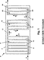
In 1 ist ein einzelner Reaktandenabschnitt eines Serpentinen-Brennstoffzellenstapels 2 mit einem Stapelgehäuse 4 gezeigt. Eine erste Zellengruppe 6 umfasst eine Einlasssammelleitung 8, die eine Einlassströmung für jede einer Vielzahl paralleler erster Brennstoffzellen 10 vorsieht. Eine Strömung durch jede der ersten Brennstoffzellen 10 entlädt sich in eine erste kombinierte Sammelleitung 12. Die erste kombinierte Sammelleitung 12 sieht ferner eine Einlassströmung für jede einer Vielzahl paralleler zweiter Brennstoffzellen 14 einer zweiten Zellengruppe 16 vor. Eine Strömung durch jede der zweiten Brennstoffzellen 14 entlädt sich in eine zweite kombinierte Sammelleitung 18. Die zweite kombinierte Sammelleitung 18 sieht eine Einlassströmung für jede einer Vielzahl paralleler dritter Brennstoffzellen 20 einer dritten Zellengruppe 22 vor.In 1 is a single reactant section of a serpentine fuel cell stack 2 with a stack case 4 shown. A first cell group 6 includes an intake manifold 8th that includes an inlet flow for each of a plurality of parallel first fuel cells 10 provides. A flow through each of the first fuel cells 10 discharges into a first combined manifold 12 , The first combined manifold 12 further sees an inlet flow for each of a plurality of parallel second fuel cells 14 a second cell group 16 in front. A flow through each of the second fuel cells 14 discharges into a second combined manifold 18 , The second combined manifold 18 sees an inlet flow for each of a plurality of parallel third fuel cells 20 a third cell group 22 in front.

Eine Strömung durch die dritten Brennstoffzellen 20 entlädt sich in eine Austrittssammelleitung 24. Die Austrittssammelleitung 24 entlädt diese Reaktandenströmung von dem Stapelgehäuse 4 des Brennstoffzellenstapels 2.A flow through the third fuel cells 20 discharges into an exit trunk 24 , The discharge manifold 24 discharges this reactant flow from the stack housing 4 of the fuel cell stack 2 ,

Eine Anoden- oder Kathodenströmung tritt in den Brennstoffzellenstapel 2 in der unteren Strömungsrichtung A ein, wie gezeigt ist. Von der Einlasssammelleitung 8 wird die Einlassströmung über die Vielzahl der ersten Brennstoffzellen 10 aufgeteilt, wobei die Strömung in der ersten Zellengruppe 6 einer aufwärts gerichteten Strömungsrichtung B folgt, wie gezeigt ist. In der ersten kombinierten Sammelleitung 12 wird die gesamte Strömung der ersten Zellengruppe 6 in die Strömungsrichtung C umgelenkt, wie gezeigt ist. Die Strömung in den zweiten Brennstoffzellen 14 der zweiten Zellengruppe 16 erfolgt in einer abwärts gerichteten Strömungsrichtung D. In der zweiten kombinierten Sammelleitung 18 wird die gesamte Strömung der zweiten Zellengruppe 16 wiederum in die untere Strömungsrichtung A umgelenkt, wie gezeigt ist. Die Strömungsrichtung in den dritten Brennstoffzellen 20 der dritten Zellengruppe 22 ist ähnlich der Strömungsrichtung in der ersten Zellengruppe 6 oder erfolgt in einer aufwärts gerichteten Strömungsrichtung B, wie gezeigt ist. Die dritten Brennstoffzellen 20 entladen sich in die Austrittssammelleitung 24, und die kombinierte Strömung in der Austrittssammelleitung 24 verlässt den Stapel in der Austrittsströmungsrichtung E, wie gezeigt ist.An anode or cathode flow enters the fuel cell stack 2 in the lower flow direction A, as shown. From the intake manifold 8th the inlet flow becomes over the plurality of first fuel cells 10 split, with the flow in the first cell group 6 an upward flow direction B, as shown. In the first combined manifold 12 becomes the entire flow of the first cell group 6 deflected in the flow direction C, as shown. The flow in the second fuel cells 14 the second cell group 16 takes place in a downward flow direction D. In the second combined manifold 18 becomes the entire flow of the second cell group 16 again deflected in the lower flow direction A, as shown. The flow direction in the third fuel cells 20 the third cell group 22 is similar to the flow direction in the first cell group 6 or takes place in an upward flow direction B, as shown. The third fuel cells 20 discharge into the discharge manifold 24 , and the combined flow in the exhaust manifold 24 leaves the stack in the exit flow direction E, as shown.

In 1 ist gezeigt, dass die Strömung in jeder benachbarten Zellengruppe in entgegengesetzten Richtungen verläuft. Es ist nicht möglich, den Brennstoffzellenstapel 2 derart zu orientieren, dass jede Zelle jeder Zellengruppe eine Strömung in einer schwerkraftunterstützten Richtung, d. h. in der abwärts gerichteten Strömungsrichtung D ermöglicht. Bei der beispielhaften Anordnung von 1 ist nur die Strömung in der zweiten Zellengruppe 16 in einer schwerkraftunterstützten Strömungsrichtung abwärts gerichtet. Die Strömung in jeder Zelle von sowohl der ersten Zellengruppe 6 als auch der dritten Zellengruppe 22 verläuft gegen die Schwerkraft, und daher läuft Wasser, das in diesen Zellen gebildet wird, entweder gegen die Strömung des Reaktandengases ab oder muss durch die Reaktandengasströmung durch jede Zelle gedrängt werden. Dies stellt eine weniger geeignete Anordnung für das Wassermanagement in dem Brennstoffzellenstapel 2 dar und resultiert daher in einer schwierigeren Steuerung der relativen Feuchte in dem Brennstoffzellenstapel 2.In 1 It is shown that the flow in each adjacent cell group is in opposite directions. It is not possible to use the fuel cell stack 2 in such a way that each cell of each cell group allows a flow in a gravity assisted direction, ie, in the downward flow direction D. In the exemplary arrangement of 1 is only the flow in the second cell group 16 directed downward in a gravity assisted flow direction. The flow in each cell from both the first cell group 6 as well as the third cell group 22 runs against gravity, and therefore, water formed in these cells either runs against the flow of reactant gas or must be forced through each cell by the reactant gas flow. This provides a less suitable arrangement for water management in the fuel cell stack 2 and therefore results in a more difficult control of the relative humidity in the fuel cell stack 2 ,

In 2 ist ein beispielhafter Brennstoffzellenstapel gemäß den Grundsätzen der vorliegenden Erfindung gezeigt. 2 sieht einen Brennstoffzellenstapel 30 mit Kaskadenkonstruktion vor, der einen kaskadenartigen Stapelkörper 32 aufweist. Der kaskadenartige Stapelkörper 32 umfasst ferner ein erstes Segment 34 und ein zweites Segment 36. Es ist eine beispielhafte Strömung für einen Anodenreaktanden gezeigt.In 2 For example, an exemplary fuel cell stack is shown in accordance with the principles of the present invention. 2 sees a fuel cell stack 30 with cascade construction, which is a cascading stacked body 32 having. The cascading stacked body 32 further comprises a first segment 34 and a second segment 36 , An exemplary flow for an anode reactant is shown.

Das erste Segment 34 umfasst ferner eine Einlasssammelleitung 38 für das erste Segment in Fluidverbindung mit einer Vielzahl von Brennstoffzellen 40 des ersten Segmentes. Die Brennstoffzellen 40 des ersten Segmentes sind parallel zueinander angeordnet, wobei jede eine Reaktandenströmung aufweist, die von der Einlasssammelleitung 38 des ersten Segmentes eintritt und in eine Austragssammelleitung 42 des ersten Segmentes ausgetragen wird. Die Austrittssammelleitung 42 des ersten Segmentes steht in Fluidverbindung mit einem Separatorsegment 44.The first segment 34 further comprises an intake manifold 38 for the first segment in fluid communication with a plurality of fuel cells 40 of the first segment. The fuel cells 40 of the first segment are arranged parallel to each other, each having a reactant flow coming from the inlet manifold 38 enters the first segment and in a discharge collection 42 of the first segment is discharged. The discharge manifold 42 the first segment is in fluid communication with a separator segment 44 ,

Das Separatorsegment 44 verbindet sowohl mechanisch als auch fluidmäßig das erste Segment 34 mit dem zweiten Segment 36. Ein Separatorkanal 46 sieht eine Fluidverbindung zwischen der Austrittssammelleitung 42 des ersten Segmentes und einer Einlasssammelleitung 48 des zweiten Segmentes vor. The separator segment 44 connects both mechanically and fluidly the first segment 34 with the second segment 36 , A separator channel 46 sees a fluid connection between the outlet header 42 the first segment and an intake manifold 48 of the second segment.

Das zweite Segment 36 umfasst ferner die Einlasssammelleitung 48 des zweiten Segmentes in Fluidverbindung mit einer Vielzahl von Brennstoffzellen 50 des zweiten Segmentes. Die Brennstoffzellen 50 des zweiten Segmentes sind parallel zueinander angeordnet, wobei jede eine Reaktandenströmung aufweist, die von der Einlasssammelleitung 48 des zweiten Segmentes eintritt und in eine Austrittssammelleitung 52 des zweiten Segmentes ausgetragen wird. Bei dieser Ausführungsform sammelt die Austrittssammelleitung 52 des zweiten Segmentes die gesamte Strömung von dem Brennstoffzellenstapel 30 und trägt diese aus.The second segment 36 further comprises the intake manifold 48 of the second segment in fluid communication with a plurality of fuel cells 50 of the second segment. The fuel cells 50 of the second segment are arranged parallel to each other, each having a reactant flow coming from the inlet header 48 enters the second segment and into an outlet manifold 52 of the second segment is discharged. In this embodiment, the exhaust manifold collects 52 of the second segment, the entire flow from the fuel cell stack 30 and wears them out.

Die Segmente des Brennstoffzellenstapels 30 der vorliegenden Erfindung sind in aufeinander folgenden Paaren von Segmentes angeordnet. Das erste Segment 34 wirkt als das oberstromige Segment, wobei eine Strömung den Stapel von dem ersten Segment 34 stromabwärts zu dem zweiten Segment 36 durchquert. Wenn ein drittes (oder weitere) Segment(e) verwendet wird bzw. werden, wird das zweite Segment 36 bezüglich des dritten Segmentes (nicht gezeigt) das oberstromige Segment usw.The segments of the fuel cell stack 30 of the present invention are arranged in successive pairs of segments. The first segment 34 acts as the upstream segment, with a flow separating the stack from the first segment 34 downstream to the second segment 36 crosses. When a third (or wider) segment (s) is used, the second segment becomes 36 with respect to the third segment (not shown), the upstream segment, etc.

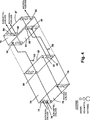
Eine Anodenströmung (gezeigt) tritt in den kaskadenartigen Brennstoffzellenstapel 30 in der Einlassströmungsrichtung F des ersten Segmentes ein. Eine Kathodenströmung (nicht gezeigt) ist ähnlich der, die in 2 gezeigt ist. Von der Einlasssammelleitung 38 des ersten Segmentes wird die Anodenströmung in die Brennstoffzellen 40 des ersten Segmentes in der Strömungsrichtung G des ersten Segmentes, wie gezeigt ist, umgelenkt. Die gesamte Einlassströmung zu dem Stapel durchquert die Brennstoffzellen 40 des ersten Segmentes. Der Austrag von den Brennstoffzellen 40 des ersten Segmentes tritt in die Austrittssammelleitung 42 des ersten Segmentes in der Austrittsrichtung H des ersten Segmentes ein.An anode stream (shown) enters the cascaded fuel cell stack 30 in the inlet flow direction F of the first segment. A cathode flow (not shown) is similar to that described in U.S. Pat 2 is shown. From the intake manifold 38 of the first segment becomes the anode flow into the fuel cells 40 the first segment in the flow direction G of the first segment, as shown, deflected. All inlet flow to the stack traverses the fuel cells 40 of the first segment. The discharge from the fuel cells 40 of the first segment enters the exit manifold 42 of the first segment in the exit direction H of the first segment.

Die gesamte, das erste Segment 34 verlassende Strömung tritt in den Separatorkanal 46 des Separatorsegmentes 44 ein und wird in der Umlenkströmungsrichtung J umgelenkt. Von dem Separatorkanal 46 wird die gesamte Strömung in die Einlasssammelleitung 48 des zweiten Segmentes 36 umgelenkt. Von der Einlasssammelleitung 48 des zweiten Segmentes wird die Strömung von der Einlassströmungsrichtung K des zweiten Segmentes in die Strömungsrichtung L des zweiten Segmentes umgelenkt. Die gesamte Strömung in dem zweiten Segment 36 strömt in die Brennstoffzellen 50 des zweiten Segmentes. Der Austrag der Brennstoffzellen 50 des zweiten Segmentes erfolgt in die Austrittssammelleitung 52 des zweiten Segmentes. Die kombinierte Strömung in der Austrittssammelleitung 52 des zweiten Segmentes verlässt den Stapel in einer Stapelauslassrichtung M.The whole, the first segment 34 leaving flow enters the separator channel 46 of the separator segment 44 and is deflected in the Umlenkströmungsrichtung J. From the separator channel 46 the entire flow is in the intake manifold 48 of the second segment 36 diverted. From the intake manifold 48 of the second segment, the flow is deflected from the inlet flow direction K of the second segment in the flow direction L of the second segment. The entire flow in the second segment 36 flows into the fuel cells 50 of the second segment. The discharge of the fuel cells 50 of the second segment takes place in the discharge manifold 52 of the second segment. The combined flow in the outlet header 52 of the second segment leaves the stack in a stack outlet direction M.

Der kaskadenartige Brennstoffzellenstapel 30 sieht einen Vorteil darin vor, dass alle Brennstoffzellen derart angeordnet sind, damit eine Strömung als ”unidirektionale” Strömung vorgesehen wird, die hier als allgemein abwärts gerichtete, schwerkraftunterstützte Strömungsrichtung definiert ist, die als die Strömungsrichtung G des ersten Segmentes bzw. als die Strömungsrichtung L des zweiten Segmentes gezeigt ist. Durch die Lieferung der unidirektionalen Strömung durch aktive Brennstoffzellen ausschließlich in der schwerkraftunterstützten Richtung wird Wasser, das durch den Reaktionsprozess erzeugt wird, sowohl durch die Strömungsgeschwindigkeit des Gases durch die Brennstoffzellen als auch durch die Schwerkraft in die Austrittssammelleitungen 42 bzw. 52 des jeweiligen Segmentes gedrängt. Durch die Anordnung des Separatorsegmentes 44 zwischen dem ersten Segment 34 und dem zweiten Segment 36, wie gezeigt ist, erreicht das Separatorsegment 44 eine durchschnittliche Betriebstemperatur des Stapels durch Wärmeleitungsübertragung von den benachbarten Stapelsegmenten wie auch Konvektionswärmeübertragung von den Stapelreaktanden und den Kühlmittelströmungen.The cascading fuel cell stack 30 provides an advantage in that all the fuel cells are arranged so as to provide a flow as a "unidirectional" flow, defined herein as a generally downward, gravity assisted flow direction, which is referred to as the flow direction G of the first segment or the flow direction L, respectively of the second segment is shown. By supplying the unidirectional flow through active fuel cells exclusively in the gravity-assisted direction, water generated by the reaction process becomes both the flow velocity of the gas through the fuel cells and gravity into the exhaust manifolds 42 respectively. 52 of the respective segment. By the arrangement of the separator segment 44 between the first segment 34 and the second segment 36 , as shown, reaches the separator segment 44 an average operating temperature of the stack by conduction transfer from the adjacent stack segments as well as convective heat transfer from the stack reactants and the coolant flows.

Im Gebrauch ist der Brennstoffzellenstapel derart ausgebildet, dass ein oberer Abschnitt 54 des Stapels vorgesehen wird, wobei eine Stapeleinlassöffnung 56 benachbart dazu angeordnet ist. In Übereinstimmung damit ist der Brennstoffzellenstapel der vorliegenden Erfindung derart ausgebildet, dass ein unterer Abschnitt 58 des Stapels vorgesehen wird, an dem eine Stapelauslassöffnung 60 angeordnet ist. Eine Anoden- oder Kathodenströmung tritt durch eine in dem oberen Abschnitt des Stapels angeordnete Öffnung ein und tritt durch den unteren Abschnitt des Stapels aus. Eine Kühlmittelströmung ist bevorzugt ähnlich angeordnet, so dass diese durch den oberen Abschnitt des Stapels eintritt und durch den unteren Abschnitt des Stapels austritt.In use, the fuel cell stack is formed such that an upper portion 54 the stack is provided, wherein a stack inlet opening 56 is arranged adjacent thereto. In accordance therewith, the fuel cell stack of the present invention is formed such that a lower portion 58 the stack is provided, at which a Stapelauslassöffnung 60 is arranged. An anode or cathode flow enters through an opening located in the upper portion of the stack and exits through the lower portion of the stack. A coolant flow is preferably similarly arranged so that it enters through the upper portion of the stack and exits through the lower portion of the stack.

Dadurch, dass das Wasser, das durch den Reaktionsprozess einer Brennstoffzelle erzeugt wird, an den unteren Abschnitt des Stapels gelenkt wird, wird das Wasser vorteilhafterweise ausgetragen. Bei der Ausführungsform von 2 der vorliegenden Erfindung wird Wasser von dem Brennstoffzellenstapel durch einen Ablass (nicht gezeigt) ausgetragen, der mit einem Separatorablassbereich N eines unteren Separatorsegmentes 62 verbunden ist. Jedes Separatorsegment besitzt einen Ablassbereich ähnlich dem Ablassbereich N des unteren Separatorsegmentes 62. Die Anordnung des Wasserablasses in dem Separatorablassbereich N sieht einen Austrag eines überwiegenden Anteils des Wassers vor, das durch jedes Stapelsegment erzeugt wird. Die relative Feuchte wird zwischen Segmenten auf etwa 100% relative Feuchtigkeit durch Entfernung der gesamten oder des größten Teils der Flüssigkeit vor dem Eintritt in das nächste Segment gesteuert.By directing the water generated by the reaction process of a fuel cell to the lower portion of the stack, the water is advantageously discharged. In the embodiment of 2 In the present invention, water is discharged from the fuel cell stack through a drain (not shown) connected to a separator discharge region N of a lower separator segment 62 connected is. Each separator segment has a drain region similar to the drain region N of the lower one Separatorsegmentes 62 , The arrangement of the water drain in the separator discharge area N provides for discharge of a major portion of the water generated by each stack segment. The relative humidity is controlled between segments to about 100% relative humidity by removing all or most of the liquid before entering the next segment.

In 3 ist eine vereinfachte Ansicht gezeigt, die zwei separate Segmente eines Brennstoffzellenstapels der vorliegenden Erfindung zeigt. Eine bevorzugte Ausführungsform mit einem größeren ersten Segment 70 von Brennstoffzellen ist benachbart einem zweiten Segment 72 mit einer kleineren Anzahl von Brennstoffzellen gezeigt. Der Einfachheit halber ist das Separatorsegment in dieser Ansicht nicht gezeigt. Das erste Segment 70 umfasst einen Kathodeneinlass 74, einen Kühlmitteleinlass 76 bzw. einen Anodeneinlass 78 an einer Einlassseite 79. Auch ist an dem ersten Segment 70 ein Anodenauslass 80, ein Kühlmittelauslass 82 bzw. ein Kathodenauslass 84 an einer Auslassseite 85 gezeigt.In 3 a simplified view showing two separate segments of a fuel cell stack of the present invention is shown. A preferred embodiment with a larger first segment 70 of fuel cells is adjacent to a second segment 72 shown with a smaller number of fuel cells. For the sake of simplicity, the separator segment is not shown in this view. The first segment 70 includes a cathode inlet 74 , a coolant inlet 76 or an anode inlet 78 on an inlet side 79 , Also is on the first segment 70 an anode outlet 80 , a coolant outlet 82 or a cathode outlet 84 on an outlet side 85 shown.

Ähnlicherweise umfasst das zweite Segment 72 einen Kathodeneinlass 86, einen Kühlmitteleinlass 88 bzw. einen Anodeneinlass 90 an einer Einlassseite 91. Das zweite Segment 72 umfasst auch einen Anodenauslass 92, einen Kühlmittelauslass 94 bzw. einen Kathodenauslass 96 an einer Auslassseite 97. Die in 3 gezeigte Legende sieht in zunehmender Größe repräsentative Öffnungen für die Ströme der Anoden-, Kühlmittel- bzw. Kathodenströmungen vor.Likewise, the second segment comprises 72 a cathode inlet 86 , a coolant inlet 88 or an anode inlet 90 on an inlet side 91 , The second segment 72 also includes an anode outlet 92 , a coolant outlet 94 or a cathode outlet 96 on an outlet side 97 , In the 3 The legend shown provides for increasing size representative openings for the streams of anode, coolant, and cathode flows, respectively.

In den 4 und 5 ist der in 3 gezeigte Brennstoffzellenstapel mit zwei Segmenten detaillierter gezeigt. Der Strömungspfad der bevorzugten Ausführungsform für einen Reformatbrennstoff ist gezeigt. Für die Verwendung des Reformat-Brennstoffes sieht die bevorzugte Ausführungsform sowohl die Kathoden- als auch die Anodenströmungseinlässe in einem oberen Abschnitt jedes Segmentes des Brennstoffzellenstapels vor. Dies sorgt für eine Strömung der Anoden- und Kathodenreaktanden von einem oberen Bereich des Stapels zu einem unteren Bereich des Stapels, d. h. der unidirektionalen Strömung abwärts in jedem Stapelsegment.In the 4 and 5 is the in 3 shown fuel cell stack shown in more detail with two segments. The flow path of the preferred embodiment for a reformate fuel is shown. For the use of the reformate fuel, the preferred embodiment provides both the cathode and anode flow inlets in an upper portion of each segment of the fuel cell stack. This provides flow of the anode and cathode reactants from an upper portion of the stack to a lower portion of the stack, ie, the unidirectional flow down each stack segment.

Wie in 4 gezeigt ist, tritt die Kathodenströmung in den Kathodeneinlass 74 ein und die Anodenströmung tritt in den Anodeneinlass 78 der Einlassseite 79 ein. Die Strömung für die Anoden- und Kathodenseiten des ersten Segmentes 70 ist in der unilateralen oder schwerkraftunterstützten Richtung von einem oberen Abschnitt des ersten Segmentes 70 zu einem unteren Abschnitt des ersten Segmentes 70 vorgesehen. Die Kathodenströmung tritt über den Kathodenauslass 84 aus, und die Anodenströmung tritt über den Anodenauslass 80 an der Auslassseite 85 aus.As in 4 is shown, the cathode flow enters the cathode inlet 74 and the anode stream enters the anode inlet 78 the inlet side 79 one. The flow for the anode and cathode sides of the first segment 70 is in the unilateral or gravity assisted direction from an upper portion of the first segment 70 to a lower portion of the first segment 70 intended. The cathode flow passes over the cathode outlet 84 out, and the anode flow passes over the anode outlet 80 on the outlet side 85 out.

Die Kathoden- als auch Anodenströmungen, die das erste Segment 70 verlassen, werden durch einen Separatorkanal (nicht gezeigt) an den oberen Abschnitt des oberen Segmentes 72 geführt, um in den Kathodeneinlass 86 bzw. den Anodeneinlass 90 an der Einlassseite 91 des zweiten Segmentes 72 einzutreten. Sowohl die Anoden- als auch Kathodenströmungen durchqueren das zweite Segment 72 von dem oberen Abschnitt des Segmentes zu dem unteren Abschnitt des Segmentes. Die Anodenströmung verlässt das zweite Segment 72 über den Anodenauslass 92, und die Kathodenströmung verlässt das zweite Segment 72 über den Kathodenauslass 96, die beide an der Auslassseite 97 angeordnet sind. Kühlmittel durchquert beide Segmente des Brennstoffzellenstapels von 4 über einen Pfad von dem Kühlmitteleinlass 76 an der Einlassseite 79 zu dem Kühlmittelauslass 82 an der Auslassseite 85 des ersten Segmentes 70 und wird anschließend durch einen Separatorkanal (nicht gezeigt) an den Kühlmitteleinlass 88 an der Einlassseite 91 geführt und durch den Kühlmittelauslass 94 an der Auslassseite 97 des zweiten Segmentes 72 ausgetragen.The cathode and anode flows are the first segment 70 Leave through a separator channel (not shown) to the upper portion of the upper segment 72 led to the cathode inlet 86 or the anode inlet 90 on the inlet side 91 of the second segment 72 enter. Both the anode and cathode flows pass through the second segment 72 from the upper portion of the segment to the lower portion of the segment. The anode flow leaves the second segment 72 via the anode outlet 92 and the cathode flow leaves the second segment 72 over the cathode outlet 96 both on the exhaust side 97 are arranged. Coolant passes through both segments of the fuel cell stack 4 via a path from the coolant inlet 76 on the inlet side 79 to the coolant outlet 82 on the outlet side 85 of the first segment 70 and is then passed through a separator channel (not shown) to the coolant inlet 88 on the inlet side 91 guided and through the coolant outlet 94 on the outlet side 97 of the second segment 72 discharged.

4 zeigt die bevorzugten Strömungspfade für die Reaktanden und das Kühlmittel durch einen beispielhaften Brennstoffzellenstapel mit zwei Segmenten der vorliegenden Erfindung. Luft und ein Reformatgas werden als die Brennstoffströme verwendet. Sowohl die Anoden- als auch Kathodengase enthalten normalerweise Inertgase als einen erheblichen Anteil (d. h. größer als 20 Vol.-%) ihres Gesamtvolumens. Sowohl die Anoden- als auch Kathodenbrennstoffströme strömen bevorzugt zuerst durch ein Segment mit der größten Menge an Brennstoffzellen, wobei Wasserstoff mit Sauerstoff reagiert, um Wasser zu bilden und elektrischen Strom zu erzeugen. Das erste Segment 70 verbraucht daher den größten Prozentsatz des Brennstoffs. Das erste Segment 70 erzeugt daher die größte Spannung. Das zweite Segment 72 mit einer verringerten Menge an Brennstoffzellen reagiert sowohl die Anoden- als auch Kathodenfluide weiter, um den Großteil des verbleibenden Wasserstoffs zu entnehmen. Das zweite Segment 72 erzeugt daher bezüglich des ersten Segmentes 70 eine niedrigere Spannung. Die Gesamtdurchschnittsspannung von dem ersten Segment 70 und dem zweiten Segment 72 ist größer als bei einem Brennstoffzellenstapel, der eine parallele Strömung durch einen einzelnen Satz von Brennstoffzellen aufweist. 4 Figure 3 shows the preferred flow paths for the reactants and the coolant through an exemplary two-segment fuel cell stack of the present invention. Air and a reformate gas are used as the fuel streams. Both the anode and cathode gases normally contain inert gases as a substantial proportion (ie greater than 20% by volume) of their total volume. Preferably, both the anode and cathode fuel streams first flow through a segment having the largest amount of fuel cells, with hydrogen reacting with oxygen to form water and generate electrical power. The first segment 70 therefore consumes the largest percentage of the fuel. The first segment 70 therefore generates the greatest tension. The second segment 72 With a reduced amount of fuel cells, both the anode and cathode fluids continue to react to remove most of the remaining hydrogen. The second segment 72 therefore generates with respect to the first segment 70 a lower voltage. The total average voltage of the first segment 70 and the second segment 72 is larger than a fuel cell stack having a parallel flow through a single set of fuel cells.

Wie in 4 gezeigt ist, tritt das Kathodengas aus dem ersten Segment 70 durch den Kathodenauslass 84 aus, wobei mitgerissenes Wasser durch einen Wasserabscheider 98 vor einem Kathodengaseintritt in das zweite Segment 72 an dem Kathodeneinlass 86 getrennt wird. Das Anodengas verlässt das erste Segment 70 durch den Anodenauslass 80. Zwischen dem ersten Segment 70 und dem zweiten Segment 72 wird mitgerissenes Wasser in dem Anodenstrom gleichermaßen über einen Wasserabscheider 100 entfernt. Der Wasserabscheider 98 und der Wasserabscheider 100 sind in getrennten Separatorsegmenten (nicht gezeigt) an dem Kathodenauslass bzw. dem Anodenauslass des ersten Segmentes 70 vorgesehen.As in 4 is shown, the cathode gas from the first segment 70 through the cathode outlet 84 out, with entrained water through a water separator 98 before a cathode gas enters the second segment 72 to the cathode inlet 86 is disconnected. The anode gas leaves the first segment 70 through the anode outlet 80 , Between the first segment 70 and the second segment 72 entrained water in the anode stream is equally through a water separator 100 away. The water separator 98 and the water separator 100 are in separate separator segments (not shown) at the cathode outlet and anode outlet of the first segment, respectively 70 intended.

In 5 ist eine perspektivische Ansicht einer weiteren Ausführungsform eines Brennstoffzellenstapels gezeigt. Der Brennstoffzellenstapel von 5 wandelt die Richtung der Reaktandenströmung in einem Strömungskanal von der in 4 gezeigten Richtung ab, so dass die Reaktandenströmung in dem Strömungskanal eines Separatorsegmentes in einer ”Kreuzstrom”-Gestaltung vorgesehen ist, wie nachfolgend detaillierter beschrieben ist, anstatt in einer allgemein vertikal aufwärts gerichteten Strömungsgestaltung, wie in 4 gezeigt ist. Eine beispielhafte Strömung von Anodengas tritt an einem oberen Abschnitt des ersten Segmentes 70 ein, wie allgemein durch einen Strömungspfeil O an dem Anodeneinlass 78 gezeigt ist. Von dem Anodeneinlass 78 tritt das Anodengas in eine Einlasssammelleitung 104 des ersten Segmentes ein. Das distale Ende der Einlasssammelleitung 104 des ersten Segmentes wird durch ein Separatorsegment 106 blockiert, wodurch die gesamte Strömung in der Einlasssammelleitung 104 des ersten Segmentes in eine Vielzahl von Zellen 108 des ersten Segmentes gedrängt wird. Die gesamte Einlassströmung durchquert abwärts die Zellen 108 des ersten Segmentes und tritt in eine Austrittssammelleitung 101 des ersten Segmentes aus. Von der Austrittssammelleitung 110 des ersten Segmentes tritt die Strömung aus dem ersten Segment 70 an einer Segmentaustrittsöffnung 112 aus und tritt in einen Separatorströmungskanal 114 des Separatorsegmentes 106 ein. Der Separatorströmungskanal 114 lenkt die Strömung aufwärts zu einer Einlasssammelleitung 116 des zweiten Segmentes 72 um. Das distale Ende der Einlasssammelleitung 116 des zweiten Segmentes wird durch entweder ein zusätzliches Separatorsegment 106 oder ein Blockierelement (nicht gezeigt) blockiert, das die gesamte Strömung in der Einlasssammelleitung 116 des zweiten Segmentes in eine Vielzahl von Zellen 118 des zweiten Segmentes drängt. Die gesamte Strömung von der Einlasssammelleitung 116 des zweiten Segmentes durchquert abwärts die Zellen 118 des zweiten Segmentes und entlädt sich in eine zweite Austrittssammelleitung 120 des zweiten Segmentes. Die Strömung verlässt das zweite Segment 72 von der Austrittssammelleitung 120 des zweiten Segmentes, wie durch den Strömungspfeil P gezeigt ist.In 5 FIG. 3 is a perspective view of another embodiment of a fuel cell stack. FIG. The fuel cell stack of 5 converts the direction of the reactant flow in a flow channel of the in 4 direction, so that the reactant flow is provided in the flow channel of a separator segment in a "cross flow" configuration, as described in more detail below, rather than in a generally vertically upward flow configuration, as in FIG 4 is shown. An exemplary flow of anode gas occurs at an upper portion of the first segment 70 as generally by a flow arrow O at the anode inlet 78 is shown. From the anode inlet 78 The anode gas enters an intake manifold 104 of the first segment. The distal end of the inlet manifold 104 of the first segment is through a separator segment 106 blocked, reducing the total flow in the intake manifold 104 of the first segment into a plurality of cells 108 the first segment is pushed. The entire inlet flow traverses the cells downwards 108 of the first segment and enters an exit manifold 101 of the first segment. From the outlet manifold 110 of the first segment, the flow exits the first segment 70 at a segment exit opening 112 and enters a separator flow channel 114 of the separator segment 106 one. The separator flow channel 114 directs the flow upwards to an intake manifold 116 of the second segment 72 around. The distal end of the inlet manifold 116 of the second segment is provided by either an additional separator segment 106 or a blocking element (not shown) blocks the entire flow in the intake manifold 116 of the second segment into a plurality of cells 118 of the second segment. The entire flow from the intake manifold 116 of the second segment traverses the cells downwards 118 of the second segment and discharges into a second exhaust manifold 120 of the second segment. The flow leaves the second segment 72 from the outlet manifold 120 of the second segment, as shown by the flow arrow P.

Wie am besten in 5 gezeigt ist, sind für das beispielhafte erste Segment 70 der Anodeneinlass 78 und eine Einlasssammelleitung 104 des ersten Segmentes bevorzugt auf einer Seite der Einlassseite 79, die dem Kathodeneinlass 74 und seiner Kathodeneinlasssammelleitung 122 (der Deutlichkeit halber in gestrichelten Linien gezeigt) entgegengesetzt ist, positioniert. Die Anodengasströmung durch die Zellen 108 des ersten Segmentes verläuft diagonal abwärts, wie gezeigt ist. Die Kathodengasströmung (nicht gezeigt) verläuft ebenfalls diagonal abwärts von der Kathodeneinlasssammelleitung 122 zu einer Kathodenaustrittssammelleitung 124, so dass die Kathoden- und Anodenströmung in einer ”Kreuzstrom”-Anordnung bezüglich zueinander vorgesehen sind. Bei einer anderen bevorzugten Ausführungsform (nicht gezeigt) sind sowohl der Anodeneinlass 78 als auch der Kathodeneinlass 74 auf der gleichen Seite der Einlassseite 79 positioniert. Bei dieser Ausführungsform sind sowohl die Anodenströmung als auch die Kathodenströmung in einer ”Parallelstrom”-Anordnung bezüglich zueinander vorgesehen, beispielsweise bei Betrachtung von der Einlassseite 79 von oben links nach unten rechts. Bei beiden Ausführungsformen der Anoden- bzw. Kathodenströmung, d. h. sowohl ”Kreuzstrom” als auch ”Parallelstrom” befinden sich sowohl die Anodenströmung als auch Kathodenströmung stets in der unidirektionalen oder allgemein abwärts gerichteten Strömungsrichtung in jeder Brennstoffzelle bezüglich des ersten Segmentes 70 und des zweiten Segmentes 72.How best in 5 are shown for the exemplary first segment 70 the anode inlet 78 and an intake manifold 104 of the first segment preferably on one side of the inlet side 79 that is the cathode inlet 74 and its cathode inlet manifold 122 (shown for clarity in dashed lines) is positioned. The anode gas flow through the cells 108 of the first segment runs diagonally downwards, as shown. The cathode gas flow (not shown) also runs diagonally downwardly from the cathode inlet header 122 to a cathode exhaust manifold 124 such that the cathode and anode streams are provided in a "cross flow" configuration with respect to each other. In another preferred embodiment (not shown), both the anode inlet 78 as well as the cathode inlet 74 on the same side of the inlet side 79 positioned. In this embodiment, both the anode flow and the cathode flow are provided in a "parallel flow" arrangement with respect to each other, for example when viewed from the inlet side 79 from top left to bottom right. In both embodiments of the anode or cathode flow, ie, both "cross flow" and "parallel flow", both the anode flow and cathode flow are always in the unidirectional or generally downward flow direction in each fuel cell with respect to the first segment 70 and the second segment 72 ,

Kühlmitteldurchgänge sind bevorzugt in einer Parallelstrombeziehung mit den Kathodenströmungsdurchgängen angeordnet. Unter Bezugnahme auf die Anodendurchgänge in jedem Stapelsegment können die Kühlmitteldurchgänge daher auch entweder in der Parallelstrom- oder Kreuzstromanordnung vorgesehen sein, wie oben beschrieben ist. Die Kühlmitteldurchgänge sind bevorzugt auch so angeordnet, dass sie der unidirektionalen Strömungsrichtung, d. h. einer allgemein abwärts gerichteten Strömungsrichtung bezüglich jedes Segmentes des Stapels folgen. Die Kühlmitteldurchgänge erfordern jedoch keine unteren Ablassbereiche, wie beispielsweise den Separatorablassbereich N von 2. Die Kühlmitteldurchgänge können daher in einer Vielzahl von Anordnungen vorgesehen sein.Coolant passages are preferably arranged in a parallel flow relationship with the cathode flow passages. Therefore, with reference to the anode passages in each stack segment, the coolant passages may also be provided in either the parallel flow or crossflow configuration as described above. The coolant passages are also preferably arranged so that they follow the unidirectional flow direction, ie a generally downward flow direction with respect to each segment of the stack. However, the coolant passages do not require lower drain regions, such as the separator drain region N of FIG 2 , The coolant passages may therefore be provided in a variety of arrangements.

Die Menge der Brennstoffzellen in jedem Segment ist einstellbar und durch den Reaktandentyp bestimmt. Jede Reaktandenströmung gelangt durch die Zellen jedes Segmentes in der unidirektionalen oder schwerkraftunterstützten Richtung, und der Reaktand wird allmählich durch jedes Segment hindurch abgereichert. Für eine gegebene Gesamteinlass- und Auslassströmung ist die Stöchiometrie jedes Segmentes des Mehrsegmentstapels höher als bei einem Stapel mit einzelnem Durchgang, bei dem alle Zellen als eine Einheit von Zellen gespeist werden. Die Gesamtstöchiometrie des kaskadenartigen Brennstoffzellenstapels der vorliegenden Erfindung ist ähnlich eines nicht kaskadenartigen Stapels, wobei jedoch die Stöchiometrie in jedem Segment des kaskadenartigen Stapels der vorliegenden Erfindung höher ist. Allgemein wird angenommen, dass Brennstoffzellenkonstruktionen etwa 10% bis 11% des Wasserstoffbrennstoffes nicht verbrauchen. Somit werden, wenn 110 Einheiten an Wasserstoff in den Stapel eintreten, etwa 100 Einheiten reagiert, um elektrischen Strom zu erzeugen, und etwa 10 Einheiten verlassen den Stapel als nicht verbrauchten Wasserstoff. Die Stöchiometrie beträgt daher 110/100 = 1,1.The amount of fuel cells in each segment is adjustable and determined by the type of reactant. Each reactant stream passes through the cells of each segment in the unidirectional or gravity-assisted direction, and the reactant is gradually depleted through each segment. For a given total inlet and outlet flow, the stoichiometry of each segment of the multi-segment stack is higher than for a single-passage stack in which all cells are fed as a unit of cells. The overall stoichiometry of the cascaded fuel cell stack of the present invention The invention is similar to a non-cascade stack, however, the stoichiometry is higher in each segment of the cascaded stack of the present invention. Generally, it is believed that fuel cell designs do not consume about 10% to 11% of the hydrogen fuel. Thus, when 110 units of hydrogen enter the stack, about 100 units react to generate electrical power and about 10 units leave the stack as unused hydrogen. The stoichiometry is therefore 110/100 = 1.1.

Wenn der kaskadenartige Stapel unterteilt wird, so dass ein Stapel mit 100 Zellen ein erstes Segment mit 67 Zellen und ein zweites Segment mit 33 Zellen umfasst, besitzen beide Segmente andere höhere Stöchiometrien als der Stapel insgesamt. Bei einer beispielhaften Anordnung, bei der dieselbe Wasserstoffströmung wie oben gegeben ist, ist immer noch eine Gesamtstapelstöchiometrie von 1,1 vorhanden. In dem ersten Segment treten 110 Wasserstoffeinheiten ein, jedoch werden nur 67 Einheiten verbraucht, wodurch die Stöchiometrie des ersten Segmentes 110/67 = 1,64 ist. Die verbleibenden 43 Wasserstoffeinheiten treten in das zweite Segment ein, in dem 33 Einheiten verbraucht werden, was in einer Stöchiometrie des zweiten Segmentes von 43/33 = 1,30 resultiert. Die optimale Konstruktion sieht die gleiche Stöchiometrie pro Segment vor, was bei etwa einer Stöchiometrie von 1,4 bis 1,5 auftritt. Die Anzahl von Zellen in dem beispielhaften ersten Segment kann erhöht werden, um eine Stöchiometrie zwischen 1,4 bis 1,5 in beiden Segmenten zu erzeugen.When the cascading stack is divided so that a 100-cell stack includes a first 67-cell segment and a second 33-cell segment, both segments have higher stoichiometries than the stack as a whole. In an exemplary arrangement where the same hydrogen flow is given above, there is still a total stack stoichiometry of 1.1. In the first segment, there are 110 hydrogen units, but only 67 units are consumed, whereby the stoichiometry of the first segment is 110/67 = 1.64. The remaining 43 hydrogen units enter the second segment where 33 units are consumed, resulting in a stoichiometry of the second segment of 43/33 = 1.30. The optimal design provides the same stoichiometry per segment, which occurs at about a stoichiometry of 1.4 to 1.5. The number of cells in the exemplary first segment may be increased to produce a stoichiometry between 1.4 to 1.5 in both segments.

Unter Verwendung einer kaskadenartigen Stapelkonstruktion ist die Gesamtstapelspannung erhöht, während die Gesamtstapelstöchiometrie beibehalten wird. Beispielsweise erzeugt bei dem obigen Beispiel das erste Segment mit 67 Zellen eine höhere Spannung als das zweite Segment, da sowohl das Gesamtreaktandenvolumen das erste Segment durchquert als auch da die Strömungsgeschwindigkeit im ersten Segment aufgrund der geringeren Anzahl von Zellen höher ist. Die erhöhte Strömungsgeschwindigkeit und verbesserte Wasserentfernung verbessern die Reaktion von Wasserstoff und Sauerstoff im Vergleich zu einer ähnlichen Gruppe von Zellen einer Stapelkonstruktion mit einzelnem Durchgang. Die Spannung des zweiten oder der weiteren Stapelsegmente ist im Durchschnitt allgemein geringer, da das erste Stapelsegment das größte Volumen an verfügbarem Wasserstoff reagiert hat, wobei jedoch mit den Verbesserungen der vorliegenden Erfindung der Wirkungsgrad jedes Segmentes verbessert wird.Using a cascading stack construction, the overall stack tension is increased while maintaining the overall stack stoichiometry. For example, in the above example, the first segment of 67 cells generates a higher voltage than the second segment because both the total reactant volume traverses the first segment and because the flow velocity in the first segment is higher due to the smaller number of cells. The increased flow rate and improved water removal enhance the reaction of hydrogen and oxygen as compared to a similar group of cells of a single pass stack construction. The voltage of the second or further stack segments is generally lower on average because the first stack segment has reacted the largest volume of available hydrogen, however, with the improvements of the present invention, the efficiency of each segment is improved.

Bei einer bevorzugten Ausführungsform für Reformatbrennstoff treten die Anoden- und Kathodenströmungen in den Stapel an einem oberen Abschnitt des Segmentes des ersten Stapels ein. Die Strömung durch jedes Segment verläuft unidirektional, d. h. in der schwerkraftunterstützten, allgemein abwärts gerichteten Richtung für jedes der Fluide. Wasser, das in einem der Anoden- oder Kathodenelemente erzeugt wird, sammelt sich und wird an dem unteren Bereich jedes Separatorkanals ausgetragen, wie oben beschrieben ist. Da die Separatorkanäle zwischen den Stapelsegmenten angeordnet sind, wird die Kanaltemperatur automatisch durch die Kühlmitteltemperatur gesteuert. Die Gastemperatur in jedem der Separatorkanäle wird daher auf die Kühlmitteltemperatur solange eingestellt, bis Wasserdampf in den Separatorkanälen die Taupunkttemperatur des Kanals bzw. des Kühlmittels erreicht und jegliches überschüssiges flüssiges Wasser an den Separatorablass abläuft. Ein Vorteil dieser ”automatischen” Temperatursteuerung besteht dann, dass das Reaktandengas, das in jedes Segment eintritt, sich bei etwa 100% relativer Feuchte befindet.In a preferred reformate fuel embodiment, the anode and cathode flows enter the stack at an upper portion of the segment of the first stack. The flow through each segment is unidirectional, i. H. in the gravity-assisted, generally downward direction for each of the fluids. Water generated in one of the anode or cathode members collects and is discharged at the lower portion of each separator channel as described above. Since the separator channels are arranged between the stack segments, the channel temperature is automatically controlled by the coolant temperature. The gas temperature in each of the separator channels is therefore adjusted to the coolant temperature until water vapor in the separator channels reaches the dew point temperature of the channel or coolant and any excess liquid water drains to the separator drain. An advantage of this "automatic" temperature control is that the reactant gas entering each segment is at about 100% relative humidity.

Sowohl die Anoden- als auch Kathodengase, die den Einlass zu nachfolgenden Segmenten erreichen, befinden sich bei etwa 100% relativer Feuchte, wodurch eine gesättigte Strömung an jedes Segment geliefert wird. Dies beseitigt den Bedarf, eine zusätzliche Außentemperatursteuerung für jedes Segment vorzusehen. Wenn der Brennstoff in jedem einzelnen Segment reagiert, steigt die durchschnittliche Temperatur der Strömung von einem Segment zu dem nächsten an, und die relative Feuchte wird bei etwa 100% relativer Feuchte beibehalten, da das flüssige Wasser zwischen den Segmenten effizient durch die schwerkraftunterstützten Strömungspfade der Segmente und die Verwendung von Separatorkanälen entfernt wird.Both the anode and cathode gases, which reach the inlet to subsequent segments, are at about 100% relative humidity, providing a saturated flow to each segment. This eliminates the need to provide additional outdoor temperature control for each segment. As the fuel in each segment reacts, the average temperature of the flow increases from one segment to the next, and the relative humidity is maintained at about 100% relative humidity because the liquid water between the segments efficiently through the gravity-assisted flow paths of the segments and the use of separator channels is removed.

Der Brennstoffzellenstapel der vorliegenden Erfindung sieht verschiedene Vorteile vor. Jedes Segment des Brennstoffzellenstapels der vorliegenden Erfindung sieht eine schwerkraftunterstützte Strömung vor, und ein Separatorsegment, das zwischen jedem der Segmente angeordnet ist, beseitigt effizient Wasser von dem Stapel und steuert auch die Feuchte in dem Stapel. Durch Bereitstellen der schwerkraftunterstützten Strömung in jedem Segment und durch Bereitstellen einzelner Segmente mit verschiedenen Mengen von Brennstoffzellenelementen erlaubt die vorliegende Erfindung, dass ein Brennstoffzellenstapel bei variierenden Stöchiometrien zwischen einzelnen Segmenten arbeiten und einen höheren Betriebswirkungsgrad vorsehen kann. Die durchschnittliche Spannungsabgabe eines Brennstoffzellenstapels der vorliegenden Erfindung ist gegenüber der eines Brennstoffzellenstapels mit einer Gesamtströmung durch lediglich ein Segment aus Elementen erhöht. Die Gesamtdurchschnittsstapelspannung ist ebenfalls höher als bei einem nicht kaskadenartigen Stapel.The fuel cell stack of the present invention provides several advantages. Each segment of the fuel cell stack of the present invention provides gravity assisted flow, and a separator segment disposed between each of the segments efficiently removes water from the stack and also controls the moisture in the stack. By providing the gravity assisted flow in each segment and providing individual segments with different amounts of fuel cell elements, the present invention allows a fuel cell stack to operate with varying stoichiometries between individual segments and provide a higher operating efficiency. The average voltage output of a fuel cell stack of the present invention is increased over that of a fuel cell stack having a total flow through only a segment of elements. The overall average stack voltage is also higher than a non-cascade stack.

Die Beschreibung der Erfindung ist lediglich beispielhafter Natur und somit sind Abwandlungen, die nicht von der Grundidee der Erfindung abweichen, als innerhalb des Schutzumfangs der Erfindung anzusehen. Derartige Abwandlungen sind nicht als Abweichung vom Schutzumfang der Erfindung anzusehen.The description of the invention is merely exemplary in nature and, thus, variations which do not depart from the gist of the invention are to be considered within the scope of the invention. Such modifications are not to be regarded as a departure from the scope of the invention.

Claims (17)

Brennstoffzellenstapel mit: einer Vielzahl von Brennstoffzellen (40, 50), die in zumindest zwei Brennstoffzellensegmente (34, 36; 70, 72) unterteilt sind, von denen jedes einen Anteil der Vielzahl von Brennstoffzellen (40, 50), die darin angeordnet sind, aufweist, und die als aufeinander folgende oberstromige und unterstromige Paare von Segmenten (34, 36; 70, 72) angeordnet sind; wobei jeder der Anteile der Brennstoffzellen jedes Segmentes (34, 36; 70, 72) eine Vielzahl von Reaktandengasdurchgängen aufweist, die mit einem gemeinsamen Einlassreaktandengasdurchgang (38, 48) und einem gemeinsamen Auslassreaktandengasdurchgang (42, 52) versehen sind; wobei jedes Paar von Segmenten (34, 36; 70, 72) ein Separatorsegment (44) aufweist, das zwischen dem oberstromigen Segment (34) und dem unterstromigen Segment (36) angeordnet ist, wobei das Separatorsegment (44) in Fluidverbindung mit dem gemeinsamen Auslassreaktandengasdurchgang (42) des oberstromigen Segmentes (34) und dem gemeinsamen Einlassreaktandengasdurchgang (48) des unterstromigen Segmentes (36) desselben Segmentpaares (34, 36; 70, 72) steht; wobei jeder der Vielzahl von Reaktandengasdurchgängen der zumindest zwei Brennstoffzellensegmente (34, 36; 70, 72) in einer unidirektionalen, schwerkraftunterstützten Strömungsrichtung (G, L) angeordnet ist und die Vielzahl von Reaktandengasdurchgängen eine Gruppe von Anodengasdurchgängen und eine Gruppe von Kathodengasdurchgängen umfasst; und wobei die Menge von Brennstoffzellen in jedem Segment (34, 36; 70, 72) der zumindest zwei Brennstoffzellensegmente unterschiedlich ist.Fuel cell stack comprising: a plurality of fuel cells ( 40 . 50 ), which in at least two fuel cell segments ( 34 . 36 ; 70 . 72 ), each of which comprises a portion of the plurality of fuel cells ( 40 . 50 ) arranged therein, and which are arranged as successive upstream and downstream pairs of segments ( 34 . 36 ; 70 . 72 ) are arranged; wherein each of the portions of the fuel cells of each segment ( 34 . 36 ; 70 . 72 ) has a plurality of reactant gas passages connected to a common inlet reactant gas passage ( 38 . 48 ) and a common outlet reactant gas passage ( 42 . 52 ) are provided; each pair of segments ( 34 . 36 ; 70 . 72 ) a separator segment ( 44 ) located between the upstream segment ( 34 ) and the downstream segment ( 36 ), wherein the separator segment ( 44 ) in fluid communication with the common outlet reactant gas passageway ( 42 ) of the upstream segment ( 34 ) and the common inlet reactant gas passageway ( 48 ) of the downstream segment ( 36 ) of the same segment pair ( 34 . 36 ; 70 . 72 ) stands; wherein each of the plurality of reactant gas passages of the at least two fuel cell segments ( 34 . 36 ; 70 . 72 ) in a unidirectional, gravity assisted flow direction (G, L), and the plurality of reactant gas passages comprises a group of anode gas passages and a group of cathode gas passages; and wherein the amount of fuel cells in each segment ( 34 . 36 ; 70 . 72 ) of the at least two fuel cell segments is different. Brennstoffzellenstapel nach Anspruch 1, ferner umfassend, dass: jedes Paar der zumindest zwei Brennstoffzellensegmente (34, 36; 70, 72) als benachbarte Segmente angeordnet sind, die durch das Separatorsegment (44) getrennt sind, wobei das Separatorsegment (44) zwischen jedem Paar der zumindest zwei Brennstoffzellensegmente (34, 36; 70, 72) eine damit zusammenhängende strukturelle Verbindung bildet; und wobei jeder Separatorkanal (46) einen allgemein aufwärts orientierten Strömungsdurchgang aufweist, der eine Fluidverbindung zwischen dem gemeinsamen Auslassreaktandengasdurchgang (42) des oberstromigen Segmentes (34) und dem gemeinsamen Einlassreaktandengasdurchgang (48) des unterstromigen Segmentes (36) vorsieht.The fuel cell stack of claim 1, further comprising: each pair of said at least two fuel cell segments ( 34 . 36 ; 70 . 72 ) are arranged as adjacent segments that pass through the separator segment ( 44 ), the separator segment ( 44 ) between each pair of the at least two fuel cell segments ( 34 . 36 ; 70 . 72 ) forms a related structural compound; and wherein each separator channel ( 46 ) has a generally upwardly oriented flow passage which establishes fluid communication between the common outlet reactant gas passageway (15). 42 ) of the upstream segment ( 34 ) and the common inlet reactant gas passageway ( 48 ) of the downstream segment ( 36 ). Brennstoffzellenstapel nach Anspruch 1, ferner umfassend, dass: die Gruppe von Anodengasdurchgängen in Fluidverbindung mit einem Stapelanodeneinlasskanal (78, 90) durch einen vorgewählten der gemeinsamen Einlassreaktandengasdurchgänge steht; und die Gruppe von Anodengasdurchgängen in Fluidverbindung mit einem Stapelanodenauslasskanal (80, 92) durch einen vorgewählten der gemeinsamen Auslassreaktandengasdurchgänge steht.The fuel cell stack of claim 1, further comprising: the group of anode gas passages in fluid communication with a stack anode inlet channel (10); 78 . 90 ) through a preselected one of the common inlet reactant gas passages; and the group of anode gas passages in fluid communication with a stack anode exhaust channel (US Pat. 80 . 92 ) through a preselected one of the common outlet reactant gas passages. Brennstoffzellenstapel nach Anspruch 3, ferner umfassend, dass: die Gruppe von Kathodengasdurchgängen in Fluidverbindung mit einem Stapelkathodeneinlasskanal (74, 86) durch einen vorgewählten der gemeinsamen Einlassreaktandengasdurchgänge steht; und die Gruppe von Kathodengasdurchgängen in Fluidverbindung mit einem Stapelkathodenauslasskanal (84, 96) durch einen vorgewählten der gemeinsamen Auslassreaktandengasdurchgänge steht.The fuel cell stack of claim 3, further comprising: the group of cathode gas passages in fluid communication with a stack cathode inlet channel (10); 74 . 86 ) through a preselected one of the common inlet reactant gas passages; and the group of cathode gas passages in fluid communication with a stack cathode exhaust channel (US Pat. 84 . 96 ) through a preselected one of the common outlet reactant gas passages. Brennstoffzellenstapel nach Anspruch 4, wobei jeder Durchgang der Gruppe von Kathodengasdurchgängen in einer Kreuzstrombeziehung zu einem Gegendurchgang der Gruppe von Anodengasdurchgängen angeordnet ist.The fuel cell stack of claim 4, wherein each passage of the group of cathode gas passages is arranged in a cross-flow relationship with a counter passage of the group of anode gas passages. Brennstoffzellenstapel nach Anspruch 4, wobei jeder Durchgang der Gruppe von Kathodengasdurchgängen in einer Parallelstrombeziehung zu einem Gegendurchgang der Gruppe von Anodengasdurchgängen angeordnet ist.The fuel cell stack of claim 4, wherein each passage of the group of cathode gas passages is arranged in a parallel flow relationship to a counter passage of the group of anode gas passages. Brennstoffzellenstapel nach Anspruch 1, ferner mit einer Gruppe von Kühlmitteldurchgängen, die in Fluidverbindung mit einem Stapelkühlmitteleinlasskanal (76, 88) durch einen gemeinsamen Einlasskühlmitteldurchgang stehen, wobei die Gruppe von Kühlmitteldurchgängen in Fluidverbindung mit einem Stapelkühlmittelauslasskanal (82, 94) steht.The fuel cell stack of claim 1, further comprising a group of coolant passages in fluid communication with a stack coolant inlet channel (10). 76 . 88 ) through a common inlet coolant passage, the group of coolant passages being in fluid communication with a stack coolant outlet channel (US Pat. 82 . 94 ) stands. Brennstoffzellenstapel nach Anspruch 7, wobei jeder Durchgang der Gruppe von Kühlmitteldurchgängen benachbart und in einer Parallelstrombeziehung zu einem Gegendurchgang zumindest eines der Gruppe aus Anodengasdurchgängen und der Gruppe aus Kathodengasdurchgängen angeordnet ist.The fuel cell stack of claim 7, wherein each passage of the group of coolant passages is disposed adjacent and in parallel flow relation to a counter passage of at least one of anode anode gas passageway and cathode gas passageway assembly. Brennstoffzellenstapel nach Anspruch 1, wobei die Menge von Brennstoffzellen in jedem Segment (70, 72) zwischen jedem Segment von einem Einlassabschnitt des Stapels zu einem Auslassabschnitt des Stapels abnimmt.A fuel cell stack according to claim 1, wherein the quantity of fuel cells in each segment ( 70 . 72 ) between each segment decreases from an inlet portion of the stack to an outlet portion of the stack. Brennstoffzellenstapel mit: einer Vielzahl von Brennstoffzellen (40, 50), von denen jede einen Anodenkatalysator auf einer ersten Seite und einen Kathodenkatalysator auf einer zweiten Seite umfasst; einer Vielzahl von Anodengasdurchgängen, wobei jeder Durchgang benachbart einer jeweiligen der ersten Seiten der Vielzahl von Brennstoffzellen (40, 50) angeordnet ist; einer Vielzahl von Kathodengasdurchgängen, wobei jeder Durchgang benachbart einer jeweiligen der zweiten Seiten eines jeweiligen der Vielzahl von Brennstoffzellen (40, 50; 70, 72) angeordnet ist; wobei die Vielzahl von Brennstoffzellen (40, 50) in zumindest zwei Paaren benachbarter Segmente (34, 36; 70, 72) von Zellen angeordnet ist, wobei die Vielzahl von Anodengasdurchgängen und Kathodengasdurchgängen der Vielzahl von Brennstoffzellen (40, 50) in einer unidirektionalen, schwerkraftunterstützten Strömungsrichtung (G, L) in jedem benachbarten Segment (34, 36; 70, 72) des Stapels vorgesehen sind; wobei jedes der zumindest zwei benachbarten Segmente zumindest ein Separatorsegment (44; 106) umfasst, das dazwischen angeordnet ist und einen allgemein aufwärts gerichteten Strömungsdurchgang zur Verbindung der Vielzahl der Anodengasdurchgänge und der Kathodengasdurchgänge der benachbarten Segmente (34, 36; 70, 72) definiert; und wobei jedes Separatorsegment einen Separatorablassbereich (N) aufweist, an dem ein Wasserablass angeordnet ist. Brennstoffzellenstapel nach Anspruch 10, ferner mit: einem Anodengasseparatorkanal, der zwischen jedem Paar benachbarter Segmente (34, 36; 70, 72) in Fluidverbindung mit den Anodengasdurchgängen in jedem Paar benachbarter Segmente (34, 36; 70, 72) angeordnet ist; und einem Kathodengasseparatorkanal, der zwischen jedem Paar benachbarter Segmente (34, 36; 70, 72) in Fluidverbindung mit den Kathodengasdurchgängen in jedem Paar benachbarter Segmente (34, 36; 70, 72) angeordnet ist.Fuel cell stack with: a plurality of fuel cells ( 40 . 50 each comprising an anode catalyst on a first side and a cathode catalyst on a second side; a plurality of anode gas passages, each passage adjacent to a respective one of the first sides of the plurality of fuel cells ( 40 . 50 ) is arranged; a plurality of cathode gas passages, each passage adjacent to a respective one of the second sides of a respective one of the plurality of fuel cells (FIG. 40 . 50 ; 70 . 72 ) is arranged; wherein the plurality of fuel cells ( 40 . 50 ) in at least two pairs of adjacent segments ( 34 . 36 ; 70 . 72 ) is arranged by cells, wherein the plurality of anode gas passages and cathode gas passages of the plurality of fuel cells ( 40 . 50 ) in a unidirectional, gravity-assisted flow direction (G, L) in each adjacent segment (FIG. 34 . 36 ; 70 . 72 ) of the stack are provided; wherein each of the at least two adjacent segments comprises at least one separator segment ( 44 ; 106 ) disposed therebetween and having a generally upward flow passage for communicating the plurality of anode gas passages and the cathode gas passages of the adjacent segments (FIG. 34 . 36 ; 70 . 72 ) Are defined; and wherein each separator segment has a Separatorablassbereich (N) on which a water drain is arranged. The fuel cell stack of claim 10, further comprising: an anode gas separator channel disposed between each pair of adjacent segments (10); 34 . 36 ; 70 . 72 ) in fluid communication with the anode gas passages in each pair of adjacent segments ( 34 . 36 ; 70 . 72 ) is arranged; and a cathode gas separator channel located between each pair of adjacent segments (FIG. 34 . 36 ; 70 . 72 ) in fluid communication with the cathode gas passages in each pair of adjacent segments ( 34 . 36 ; 70 . 72 ) is arranged. Brennstoffzellenstapel nach Anspruch 11, wobei ein Kühlmitteldurchgang, zwischen jeder der ersten und zweiten Seiten beliebiger zwei aufeinander folgender Brennstoffzellen der Vielzahl von Brennstoffzellen (40, 50) angeordnet ist.The fuel cell stack of claim 11, wherein a coolant passageway between each of the first and second sides of any two consecutive fuel cells of the plurality of fuel cells ( 40 . 50 ) is arranged. Brennstoffzellenstapel nach Anspruch 12, wobei ein Kühlmittelseparatorkanal zwischen jedem Paar benachbarter Segmente (34, 36; 70, 72) in Fluidverbindung mit den Kühlmitteldurchgängen der Brennstoffzellen (40, 50) in jedem Paar benachbarter Segmente (34, 36; 70, 72) angeordnet ist.A fuel cell stack according to claim 12, wherein a coolant separator channel is provided between each pair of adjacent segments (10). 34 . 36 ; 70 . 72 ) in fluid communication with the coolant passages of the fuel cells ( 40 . 50 ) in each pair of adjacent segments ( 34 . 36 ; 70 . 72 ) is arranged. Brennstoffzellenstapel nach Anspruch 10, wobei Wasser, das in jedem Segment aus Zellen gebildet wird, an zumindest dem Separatorablassbereich (N) ausgetragen wird.A fuel cell stack according to claim 10, wherein water formed in each segment of cells is discharged to at least the separator discharge area (N). Brennstoffzellenstapel mit: einer Vielzahl von Brennstoffzellen (40, 50; 108, 118), von denen jeder einen Anodenkatalysator an einer ersten Seite und einen Kathodenkatalysator an einer zweiten Seite umfasst; einer Vielzahl von Anodengasdurchgängen, wobei jeder Durchgang benachbart der ersten Seite eines jeweiligen der Vielzahl von Brennstoffzellen (40, 50; 108, 118) angeordnet ist; einer Vielzahl von Kathodengasdurchgängen, wobei jeder Durchgang benachbart der zweiten Seite eines jeweiligen der Vielzahl von Brennstoffzellen (40, 50; 108, 118) angeordnet ist; wobei die Vielzahl von Brennstoffzellen (40, 50; 108, 118) in zumindest zwei benachbarten Segmenten von Zellen angeordnet ist, wobei zumindest einer der Anodengasdurchgänge und der Kathodengasdurchgänge in Reihe zwischen den Segmenten (34, 36; 70, 72) vorgesehen ist, und zumindest einer der Anodengasdurchgänge und der Kathodengasdurchgänge in einer unidirektionalen, schwerkraftunterstützten Strömungsrichtung (G, L) in jedem Segment des Stapels angeordnet ist; wobei jeder der Anoden- und Kathodengasdurchgänge in zumindest einem vorgewählten Segment eine Geometrie aufweist, die so variiert wird, um einen Druckabfall der Anoden- und Kathodengasdurchgänge zu steuern; wobei jedes Segmentpaar (34, 36; 70, 72) aus einem oberstromigen Segment (34, 70) und einem unterstromigen Segment (36, 72) besteht; jedes Segment jedes Segmentpaares (34, 36; 70, 72) einen Druckabfall aufweist; und der Druckabfall des unterstromigen Segmentes (36, 72) gleich oder kleiner als der Druckabfall des oberstromigen Segmentes (34, 70) für jedes Segmentpaar von dem Einlassabschnitt des Stapels zu dem Auslassabschnitt des Stapels ist; und wobei der Druckabfall des unterstromigen Segmentes (36, 72) zumindest eines Segmentpaares dadurch verringert wird, dass eine erhöhte Brennstoffzellenbreite für jede Brennstoffzelle des unterstromigen Segmentes (36, 72) vorgesehen ist.Fuel cell stack comprising: a plurality of fuel cells ( 40 . 50 ; 108 . 118 each comprising an anode catalyst on a first side and a cathode catalyst on a second side; a plurality of anode gas passages, each passage adjacent the first side of a respective one of the plurality of fuel cells (FIGS. 40 . 50 ; 108 . 118 ) is arranged; a plurality of cathode gas passages, each passage adjacent to the second side of a respective one of the plurality of fuel cells (FIGS. 40 . 50 ; 108 . 118 ) is arranged; wherein the plurality of fuel cells ( 40 . 50 ; 108 . 118 ) is arranged in at least two adjacent segments of cells, wherein at least one of the anode gas passages and the cathode gas passages in series between the segments (FIG. 34 . 36 ; 70 . 72 ), and at least one of the anode gas passages and the cathode gas passages is arranged in a unidirectional gravity assisted flow direction (G, L) in each segment of the stack; wherein each of the anode and cathode gas passages in at least one preselected segment has a geometry that is varied to control a pressure drop of the anode and cathode gas passages; each segment pair ( 34 . 36 ; 70 . 72 ) from an upstream segment ( 34 . 70 ) and a downstream segment ( 36 . 72 ) consists; each segment of each segment pair ( 34 . 36 ; 70 . 72 ) has a pressure drop; and the pressure drop of the downstream segment ( 36 . 72 ) is equal to or less than the pressure drop of the upstream segment ( 34 . 70 ) for each segment pair from the inlet portion of the stack to the outlet portion of the stack; and wherein the pressure drop of the downstream segment ( 36 . 72 ) of at least one segment pair is reduced by an increased fuel cell width for each fuel cell of the downstream segment ( 36 . 72 ) is provided. Brennstoffzellenstapel nach Anspruch 15, wobei sich eine Anzahl von Brennstoffzellen (40, 50; 108, 118) in jedem Segment zwischen Segmentpaaren (34, 36; 70, 72) von einem Eingangsabschnitt des Stapels zu einem Auslassabschnitt des Stapels verringert.A fuel cell stack according to claim 15, wherein a number of fuel cells ( 40 . 50 ; 108 . 118 ) in each segment between segment pairs ( 34 . 36 ; 70 . 72 ) is reduced from an input portion of the stack to an outlet portion of the stack. Verfahren zum Betrieb eines Brennstoffzellenstapels mit einer Vielzahl von Brennstoffzellen (40, 50; 108, 118), von denen jede eine Vielzahl von Reaktandengasdurchgängen aufweist, die sich dazwischen erstrecken, wobei die Vielzahl von Reaktandengasdurchgängen eine Gruppe von Anodengasdurchgängen und eine Gruppe von Kathodengasdurchgängen umfasst, und mit einer kaskadenartigen Stapelkonstruktion, die einzelne Segmente (34, 36; 70, 72) mit unterschiedlichen Anzahlen von Brennstoffzellen (40, 50; 108, 118) vorsieht, wobei das Verfahren die Schritte umfasst, dass: die Segmente (34, 36; 70, 72) angeordnet werden, um benachbarte Paare von Segmenten zu bilden, wobei jedes eine Vielzahl von Brennstoffzellen mit einer variierenden Menge von Brennstoffzellen (40, 50; 108, 118) in jedem Segment umfasst, um eine Stöchiometrie jedes Segmentes zu variieren; alle Reaktandengasdurchgänge der Vielzahl von Brennstoffzellen (40, 50; 108, 118) in einer unidirektionalen, schwerkraftunterstützten Strömungsrichtung (G, L) in jedem Segment (34, 36; 70, 72) des Stapels orientiert werden; zumindest ein Separatorkanal (46; 114) zwischen jedem Segmentpaar (34, 36; 70, 72) angeordnet wird; und die Vielzahl von Reaktandengasdurchgängen zwischen jedem Segmentpaar (34, 36; 70, 72) durch den zumindest einen Separatorkanal (46; 114) verbunden wird, wobei die Reaktandengasdurchgänge in jedem Segment (34, 36; 70, 72) parallel geschaltet sind und die Reaktandengasdurchgänge jedes Segments (34, 36; 70, 72) in Reihe mit einem benachbarten Segment (34, 36; 70, 72) verbunden sind.Method for operating a fuel cell stack with a plurality of fuel cells ( 40 . 50 ; 108 . 118 each of which has a plurality of reactant gas passages extending therebetween, wherein the plurality of reactant gas passages comprises a group of anode gas passages and a group of cathode gas passages, and a cascaded stack construction comprising individual segments (FIG. 34 . 36 ; 70 . 72 ) with different numbers of fuel cells ( 40 . 50 ; 108 . 118 ), the method comprising the steps of: 34 . 36 ; 70 . 72 ) are arranged to form adjacent pairs of segments, each having a plurality of fuel cells with a varying amount of fuel cells (FIGS. 40 . 50 ; 108 . 118 ) in each segment to vary a stoichiometry of each segment; all reactant gas passages of the plurality of fuel cells ( 40 . 50 ; 108 . 118 ) in a unidirectional, gravity-assisted flow direction (G, L) in each segment ( 34 . 36 ; 70 . 72 ) of the stack; at least one separator channel ( 46 ; 114 ) between each segment pair ( 34 . 36 ; 70 . 72 ) is arranged; and the plurality of reactant gas passages between each segment pair ( 34 . 36 ; 70 . 72 ) through the at least one separator channel ( 46 ; 114 ), with the reactant gas passages in each segment ( 34 . 36 ; 70 . 72 ) are connected in parallel and the reactant gas passages of each segment ( 34 . 36 ; 70 . 72 ) in series with an adjacent segment ( 34 . 36 ; 70 . 72 ) are connected. Verfahren nach Anspruch 17, ferner mit den weiteren Schritten, dass: ein Wasservolumen von der Vielzahl von Brennstoffzellen (40, 50; 108, 118) wie auch jedem Separatorkanal (46; 114) gesammelt wird; und das Wasservolumen an zumindest einem Stapelablass (N) ausgetragen wird.The method of claim 17, further comprising the further steps of: a volume of water from said plurality of fuel cells ( 40 . 50 ; 108 . 118 ) as well as each separator channel ( 46 ; 114 ) is collected; and the volume of water is discharged at at least one stack discharge (N).
DE10393165T 2002-08-29 2003-08-20 Fuel cell stack and operating method Expired - Lifetime DE10393165B4 (en)

Applications Claiming Priority (3)

Application Number Priority Date Filing Date Title
US10/230,916 US6794068B2 (en) 2002-08-29 2002-08-29 Fuel cell stack design and method of operation
US10/230,916 2002-08-29
PCT/US2003/026041 WO2004021473A1 (en) 2002-08-29 2003-08-20 Fuel cell stack design and method of operation

Publications (2)

Publication Number Publication Date
DE10393165T5 DE10393165T5 (en) 2006-01-12
DE10393165B4 true DE10393165B4 (en) 2012-11-22

Family

ID=31976626

Family Applications (1)

Application Number Title Priority Date Filing Date
DE10393165T Expired - Lifetime DE10393165B4 (en) 2002-08-29 2003-08-20 Fuel cell stack and operating method

Country Status (6)

Country Link
US (1) US6794068B2 (en)
JP (1) JP4753580B2 (en)
CN (1) CN100388531C (en)
AU (1) AU2003259940A1 (en)
DE (1) DE10393165B4 (en)
WO (1) WO2004021473A1 (en)

Cited By (3)

* Cited by examiner, † Cited by third party
Publication number Priority date Publication date Assignee Title
DE102012020294A1 (en) * 2012-10-17 2014-04-17 Daimler Ag fuel cell stack
DE102016225889A1 (en) * 2016-12-21 2018-06-21 Robert Bosch Gmbh fuel cell device
US11201346B2 (en) 2018-01-17 2021-12-14 Audi Ag Cascaded fuel cell stack and fuel cell system

Families Citing this family (39)

* Cited by examiner, † Cited by third party
Publication number Priority date Publication date Assignee Title
JP3699063B2 (en) * 2002-06-26 2005-09-28 本田技研工業株式会社 Fuel cell and control method thereof
US7494735B2 (en) * 2002-08-29 2009-02-24 General Motors Corporation Fuel cell stack design and method of operation
US6939636B2 (en) 2003-04-28 2005-09-06 Relion, Inc. Air cooled fuel cell module
US7470477B2 (en) * 2003-08-14 2008-12-30 Delphi Technologies, Inc. Cascaded fuel cell stacks for fast start-up and anode coking control
US20060204831A1 (en) * 2004-01-22 2006-09-14 Yan Susan G Control parameters for optimizing MEA performance
US7479333B2 (en) * 2004-12-13 2009-01-20 Hyteon, Inc. Fuel cell stack with multiple groups of cells and flow passes
US7399549B2 (en) * 2005-04-22 2008-07-15 Gm Global Technology Operations, Inc. Altering zeta potential of dispersions for better HCD performance and dispersion stability
KR100628909B1 (en) * 2005-08-18 2006-09-27 한국과학기술연구원 Method for analyzing the performance of mea and segmented cell used for the method
US20070059580A1 (en) * 2005-09-15 2007-03-15 Budinski Michael K Design strategies for corrosion mitigation
US8007943B2 (en) * 2005-11-03 2011-08-30 GM Global Technology Operations LLC Cascaded stack with gas flow recycle in the first stage
US20070178341A1 (en) * 2006-01-27 2007-08-02 Christian Wieser Gas channel coating with water-uptake related volume change for influencing gas velocity
US7955750B2 (en) 2006-02-21 2011-06-07 GM Global Technology Operations LLC Controlled electrode overlap architecture for improved MEA durability
US7858258B2 (en) * 2006-03-03 2010-12-28 Gm Global Technology Operations, Inc. Cascaded fuel cell stack operation with anode gas recirculation
US20070207362A1 (en) * 2006-03-03 2007-09-06 Andreas Koenekamp Freeze capable compact fuel cell system with improved humidification and removal of excess water and trapped nitrogen
US8343452B2 (en) * 2006-03-20 2013-01-01 GM Global Technology Operations LLC Acrylic fiber bonded carbon fiber paper as gas diffusion media for fuel cell
US7569299B2 (en) 2006-07-25 2009-08-04 Gm Global Technology Operations, Inc. Multi-component fuel cell gasket for low temperature sealing and minimal membrane contamination
US7749632B2 (en) 2006-07-27 2010-07-06 Gm Global Technology Operations, Inc. Flow shifting coolant during freeze start-up to promote stack durability and fast start-up
CN101170192B (en) * 2006-10-27 2010-04-21 新源动力股份有限公司 Modular design method for proton exchange film fuel battery
US7883810B2 (en) 2006-11-09 2011-02-08 GM Global Technology Operations LLC Slow purge for improved water removal, freeze durability, purge energy efficiency and voltage degradation due to shutdown/startup cycling
US20080138665A1 (en) * 2006-12-06 2008-06-12 3M Innovative Properties Company Compact fuel cell stack with gas ports
US7740962B2 (en) * 2006-12-06 2010-06-22 3M Innovative Properties Company Compact fuel cell stack with current shunt
US20080138667A1 (en) * 2006-12-06 2008-06-12 3M Innovative Properties Company Compact fuel cell stack with fastening member
US20080138670A1 (en) * 2006-12-06 2008-06-12 3M Innovative Properties Company Compact fuel cell stack with multiple plate arrangement
US20080138684A1 (en) * 2006-12-06 2008-06-12 3M Innovative Properties Company Compact fuel cell stack with uniform depth flow fields
US20080199751A1 (en) * 2007-02-20 2008-08-21 Commonwealth Scientific And Industrial Research Organisation Bipolar plate for an air breathing fuel cell stack
US8026020B2 (en) 2007-05-08 2011-09-27 Relion, Inc. Proton exchange membrane fuel cell stack and fuel cell stack module
US9293778B2 (en) 2007-06-11 2016-03-22 Emergent Power Inc. Proton exchange membrane fuel cell
WO2008153073A1 (en) * 2007-06-11 2008-12-18 Ngk Spark Plug Co., Ltd. Solid state electrolyte fuel cell module
US8003274B2 (en) 2007-10-25 2011-08-23 Relion, Inc. Direct liquid fuel cell
US8168340B2 (en) * 2007-11-07 2012-05-01 GM Global Technology Operations LLC Water removal features for PEMfc stack manifolds
US8409769B2 (en) * 2007-12-07 2013-04-02 GM Global Technology Operations LLC Gas diffusion layer for fuel cell
EP2277218A4 (en) * 2008-04-11 2011-10-19 Utc Power Corp Fuel cell and bipolar plate having manifold sump
EA201390436A1 (en) * 2010-09-28 2013-09-30 Топсёэ Фуль Селл А/С FUEL ELEMENT AND ELECTROLYTIC CELL WITH COUPLING FLOW / COUNTER DIRECTIONS
DK2757623T3 (en) 2011-09-16 2018-05-28 Ngk Spark Plug Co fuel cell
JP5981379B2 (en) * 2013-03-29 2016-08-31 日本特殊陶業株式会社 Fuel cell
DE102015215201A1 (en) * 2015-08-10 2017-02-16 Volkswagen Ag Fuel cell stack with internal particle retention function as well as vehicle with such a fuel cell stack
DE102015215497A1 (en) * 2015-08-13 2017-02-16 Volkswagen Aktiengesellschaft Fuel cell stack with variable segmentation and fuel cell system and vehicle with such
EP3537526B1 (en) * 2016-11-04 2023-08-02 Morimura Sofc Technology Co., Ltd. Electrochemical cell stack
CN111821768B (en) * 2020-07-27 2022-05-03 上海捷氢科技股份有限公司 Water separator and fuel cell

Citations (5)

* Cited by examiner, † Cited by third party
Publication number Priority date Publication date Assignee Title
DE3323491A1 (en) * 1982-07-09 1984-01-12 General Electric Co., Schenectady, N.Y. FUEL CELL BATTERY WITH SEPARATORS
US5478662A (en) * 1992-11-05 1995-12-26 Siemens Aktiengesellschaft Method and apparatus for disposing of water and/or inert gas from a fuel cell block
US5763113A (en) * 1996-08-26 1998-06-09 General Motors Corporation PEM fuel cell monitoring system
DE10054444A1 (en) * 1999-11-03 2001-05-10 Vaillant Joh Gmbh & Co Fuel cell has cross-section of meandering channel supplying fuel cell membrane increasing in flow direction according to linear, exponential or step function
DE10243163B4 (en) * 2001-09-17 2006-09-14 Honda Giken Kogyo K.K. fuel cell stack

Family Cites Families (13)

* Cited by examiner, † Cited by third party
Publication number Priority date Publication date Assignee Title
DE2044068A1 (en) 1970-09-05 1972-03-16 Siemens Ag Fuel battery
US3935028A (en) 1971-06-11 1976-01-27 Siemens Aktiengesellschaft Fuel cell set and method
US4080487A (en) 1977-02-09 1978-03-21 United Technologies Corporation Process for cooling molten carbonate fuel cell stacks and apparatus therefor
US4722873A (en) 1985-12-06 1988-02-02 Mitsubishi Denki Kabushiki Kaisha Fuel cell power generating system
US5272017A (en) 1992-04-03 1993-12-21 General Motors Corporation Membrane-electrode assemblies for electrochemical cells
US5413878A (en) 1993-10-28 1995-05-09 The United States Of America As Represented By The Department Of Energy System and method for networking electrochemical devices
US5518828A (en) 1994-07-21 1996-05-21 Bechtel Group, Inc. Thermal integration of an air-cooled fuel cell stack
US5798187A (en) * 1996-09-27 1998-08-25 The Regents Of The University Of California Fuel cell with metal screen flow-field
US5776624A (en) 1996-12-23 1998-07-07 General Motors Corporation Brazed bipolar plates for PEM fuel cells
US6218038B1 (en) 1999-08-24 2001-04-17 Plug Power, Inc. Regulating a flow through a fuel cell
US20030022050A1 (en) * 2001-07-25 2003-01-30 Ballard Power Systems Inc. Product water pump for fuel cell system
JP3914418B2 (en) * 2001-11-20 2007-05-16 本田技研工業株式会社 Fuel cell stack
US6911277B2 (en) * 2002-05-01 2005-06-28 General Motors Corporation Device and method to expand operating range of a fuel cell stack

Patent Citations (5)

* Cited by examiner, † Cited by third party
Publication number Priority date Publication date Assignee Title
DE3323491A1 (en) * 1982-07-09 1984-01-12 General Electric Co., Schenectady, N.Y. FUEL CELL BATTERY WITH SEPARATORS
US5478662A (en) * 1992-11-05 1995-12-26 Siemens Aktiengesellschaft Method and apparatus for disposing of water and/or inert gas from a fuel cell block
US5763113A (en) * 1996-08-26 1998-06-09 General Motors Corporation PEM fuel cell monitoring system
DE10054444A1 (en) * 1999-11-03 2001-05-10 Vaillant Joh Gmbh & Co Fuel cell has cross-section of meandering channel supplying fuel cell membrane increasing in flow direction according to linear, exponential or step function
DE10243163B4 (en) * 2001-09-17 2006-09-14 Honda Giken Kogyo K.K. fuel cell stack

Cited By (4)

* Cited by examiner, † Cited by third party
Publication number Priority date Publication date Assignee Title
DE102012020294A1 (en) * 2012-10-17 2014-04-17 Daimler Ag fuel cell stack
US9882230B2 (en) 2012-10-17 2018-01-30 Daimler Ag Fuel cell stack
DE102016225889A1 (en) * 2016-12-21 2018-06-21 Robert Bosch Gmbh fuel cell device
US11201346B2 (en) 2018-01-17 2021-12-14 Audi Ag Cascaded fuel cell stack and fuel cell system

Also Published As

Publication number Publication date
JP2005537625A (en) 2005-12-08
DE10393165T5 (en) 2006-01-12
US6794068B2 (en) 2004-09-21
AU2003259940A1 (en) 2004-03-19
CN100388531C (en) 2008-05-14
US20040043279A1 (en) 2004-03-04
JP4753580B2 (en) 2011-08-24
WO2004021473A1 (en) 2004-03-11
CN1695259A (en) 2005-11-09

Similar Documents

Publication Publication Date Title
DE10393165B4 (en) Fuel cell stack and operating method
DE102006019114B4 (en) Fuel cell system for improved hydrogen and oxygen use
DE112005001086B4 (en) Coolant flow field geometry with branched fluid channels for improved fluid flow through a fuel cell, separator plate and fuel cell
DE10226962B4 (en) fuel cell
DE10321916B4 (en) Separator unit and fuel cell with separator unit
DE102008006735B4 (en) Fuel cell system and designated Wasserdampfübertragungseinheit
DE112005001966B4 (en) Fuel cell stack design
DE102007008474B4 (en) Plate and anode plate for a fuel cell
DE112004001832T5 (en) Fuel cell system and fuel cell motor vehicle
DE102006017943A1 (en) Fuel cell construction with integrated heat exchanger and gas humidification unit
DE10243163B4 (en) fuel cell stack
DE102004008704A1 (en) Hydrogen recirculation without a pump
DE19743067C2 (en) Flow module with flow chambers for three or four fluids
DE102004058117B4 (en) Thickness-optimized bipolar plate for fuel cell stack and bipolar plate arrangement in a fuel cell stack
DE102019200449A1 (en) Humidifier with coolant tubes and fuel cell device
DE102006046725B4 (en) Arrangement for electrochemical conversion and method for operating this
EP1378018B1 (en) Electrochemical fuel cell stack
DE102005037093B4 (en) Fuel cell with fluid guide channels with oppositely changing flow cross sections
DE10342470A1 (en) Device for flowing at least one fuel cell with a medium and fuel cell system
DE10226388A1 (en) Separator for fuel cells
EP4073859A1 (en) Kit for a fuel cell stack and method for producing a fuel cell stack
DE102005026909B4 (en) Fuel cell stack and separator plate for uniform Reaktandendurchflussmengenverteilung
WO2002097908A2 (en) Interconnector for a fuel cell
DE102015100704B3 (en) Cathode plate of a bipolar element and method of operating such a cathode plate
DE10394056B4 (en) PEM fuel cell with a flow restrictor in a fuel cell flow field

Legal Events

Date Code Title Description
OP8 Request for examination as to paragraph 44 patent law

Ref document number: 10393165

Country of ref document: DE

Date of ref document: 20060112

Kind code of ref document: P

8125 Change of the main classification

Ipc: H01M 8/04 AFI20051017BHDE

8180 Miscellaneous part 1

Free format text: PFANDRECHT

8180 Miscellaneous part 1

Free format text: PFANDRECHT AUFGEHOBEN

8180 Miscellaneous part 1

Free format text: PFANDRECHT

R018 Grant decision by examination section/examining division
R020 Patent grant now final

Effective date: 20130223

R071 Expiry of right