CN103247109A - Plug-in electric vehicle charging station with vending machine payment options - Google Patents
Plug-in electric vehicle charging station with vending machine payment options Download PDFInfo
- Publication number
- CN103247109A CN103247109A CN2013100488557A CN201310048855A CN103247109A CN 103247109 A CN103247109 A CN 103247109A CN 2013100488557 A CN2013100488557 A CN 2013100488557A CN 201310048855 A CN201310048855 A CN 201310048855A CN 103247109 A CN103247109 A CN 103247109A
- Authority
- CN
- China
- Prior art keywords
- rev
- interface
- charging station
- payment
- identifying code
- Prior art date
- Legal status (The legal status is an assumption and is not a legal conclusion. Google has not performed a legal analysis and makes no representation as to the accuracy of the status listed.)
- Pending
Links
- 238000004891 communication Methods 0.000 claims abstract description 34
- 238000000034 method Methods 0.000 claims abstract description 33
- 238000004590 computer program Methods 0.000 claims description 16
- 238000009826 distribution Methods 0.000 claims description 6
- 238000003860 storage Methods 0.000 claims description 4
- 230000008878 coupling Effects 0.000 claims 1
- 238000010168 coupling process Methods 0.000 claims 1
- 238000005859 coupling reaction Methods 0.000 claims 1
- 230000008569 process Effects 0.000 abstract description 13
- 238000010586 diagram Methods 0.000 description 15
- 230000006870 function Effects 0.000 description 9
- 238000004364 calculation method Methods 0.000 description 6
- 238000012545 processing Methods 0.000 description 6
- 238000003672 processing method Methods 0.000 description 6
- 238000007726 management method Methods 0.000 description 5
- 230000009471 action Effects 0.000 description 4
- 230000005540 biological transmission Effects 0.000 description 4
- 230000008901 benefit Effects 0.000 description 3
- 230000000694 effects Effects 0.000 description 3
- 230000005611 electricity Effects 0.000 description 3
- 238000005516 engineering process Methods 0.000 description 3
- 239000000446 fuel Substances 0.000 description 3
- 230000005284 excitation Effects 0.000 description 2
- 230000008676 import Effects 0.000 description 2
- 230000005055 memory storage Effects 0.000 description 2
- 239000004065 semiconductor Substances 0.000 description 2
- 230000000712 assembly Effects 0.000 description 1
- 238000000429 assembly Methods 0.000 description 1
- 230000003139 buffering effect Effects 0.000 description 1
- 230000001413 cellular effect Effects 0.000 description 1
- 230000008859 change Effects 0.000 description 1
- 238000006243 chemical reaction Methods 0.000 description 1
- 239000003245 coal Substances 0.000 description 1
- 238000013523 data management Methods 0.000 description 1
- 238000005034 decoration Methods 0.000 description 1
- 238000004146 energy storage Methods 0.000 description 1
- 230000006698 induction Effects 0.000 description 1
- 230000003993 interaction Effects 0.000 description 1
- 210000003127 knee Anatomy 0.000 description 1
- 238000004519 manufacturing process Methods 0.000 description 1
- 230000007246 mechanism Effects 0.000 description 1
- 238000010295 mobile communication Methods 0.000 description 1
- 230000003287 optical effect Effects 0.000 description 1
- 239000013307 optical fiber Substances 0.000 description 1
- 230000002093 peripheral effect Effects 0.000 description 1
- 239000011435 rock Substances 0.000 description 1
- 238000012360 testing method Methods 0.000 description 1
- 238000012795 verification Methods 0.000 description 1
Images

Classifications
-
- G06Q50/40—
-
- G—PHYSICS
- G07—CHECKING-DEVICES
- G07F—COIN-FREED OR LIKE APPARATUS
- G07F15/00—Coin-freed apparatus with meter-controlled dispensing of liquid, gas or electricity
- G07F15/003—Coin-freed apparatus with meter-controlled dispensing of liquid, gas or electricity for electricity
- G07F15/005—Coin-freed apparatus with meter-controlled dispensing of liquid, gas or electricity for electricity dispensed for the electrical charging of vehicles
-
- B—PERFORMING OPERATIONS; TRANSPORTING
- B60—VEHICLES IN GENERAL
- B60L—PROPULSION OF ELECTRICALLY-PROPELLED VEHICLES; SUPPLYING ELECTRIC POWER FOR AUXILIARY EQUIPMENT OF ELECTRICALLY-PROPELLED VEHICLES; ELECTRODYNAMIC BRAKE SYSTEMS FOR VEHICLES IN GENERAL; MAGNETIC SUSPENSION OR LEVITATION FOR VEHICLES; MONITORING OPERATING VARIABLES OF ELECTRICALLY-PROPELLED VEHICLES; ELECTRIC SAFETY DEVICES FOR ELECTRICALLY-PROPELLED VEHICLES
- B60L50/00—Electric propulsion with power supplied within the vehicle
- B60L50/50—Electric propulsion with power supplied within the vehicle using propulsion power supplied by batteries or fuel cells
-
- G—PHYSICS
- G06—COMPUTING; CALCULATING OR COUNTING
- G06Q—INFORMATION AND COMMUNICATION TECHNOLOGY [ICT] SPECIALLY ADAPTED FOR ADMINISTRATIVE, COMMERCIAL, FINANCIAL, MANAGERIAL OR SUPERVISORY PURPOSES; SYSTEMS OR METHODS SPECIALLY ADAPTED FOR ADMINISTRATIVE, COMMERCIAL, FINANCIAL, MANAGERIAL OR SUPERVISORY PURPOSES, NOT OTHERWISE PROVIDED FOR
- G06Q20/00—Payment architectures, schemes or protocols
- G06Q20/08—Payment architectures
- G06Q20/18—Payment architectures involving self-service terminals [SST], vending machines, kiosks or multimedia terminals
-
- G—PHYSICS
- G07—CHECKING-DEVICES
- G07F—COIN-FREED OR LIKE APPARATUS
- G07F9/00—Details other than those peculiar to special kinds or types of apparatus
- G07F9/001—Interfacing with vending machines using mobile or wearable devices
-
- G—PHYSICS
- G07—CHECKING-DEVICES
- G07F—COIN-FREED OR LIKE APPARATUS
- G07F9/00—Details other than those peculiar to special kinds or types of apparatus
- G07F9/002—Vending machines being part of a centrally controlled network of vending machines
-
- H—ELECTRICITY
- H02—GENERATION; CONVERSION OR DISTRIBUTION OF ELECTRIC POWER
- H02J—CIRCUIT ARRANGEMENTS OR SYSTEMS FOR SUPPLYING OR DISTRIBUTING ELECTRIC POWER; SYSTEMS FOR STORING ELECTRIC ENERGY
- H02J7/00—Circuit arrangements for charging or depolarising batteries or for supplying loads from batteries
-
- Y—GENERAL TAGGING OF NEW TECHNOLOGICAL DEVELOPMENTS; GENERAL TAGGING OF CROSS-SECTIONAL TECHNOLOGIES SPANNING OVER SEVERAL SECTIONS OF THE IPC; TECHNICAL SUBJECTS COVERED BY FORMER USPC CROSS-REFERENCE ART COLLECTIONS [XRACs] AND DIGESTS
- Y02—TECHNOLOGIES OR APPLICATIONS FOR MITIGATION OR ADAPTATION AGAINST CLIMATE CHANGE
- Y02T—CLIMATE CHANGE MITIGATION TECHNOLOGIES RELATED TO TRANSPORTATION
- Y02T90/00—Enabling technologies or technologies with a potential or indirect contribution to GHG emissions mitigation
- Y02T90/10—Technologies relating to charging of electric vehicles
- Y02T90/12—Electric charging stations
Abstract
A plug-in electric vehicle charging station includes a plug-in electric vehicle interface configured to process payment for charging a plug-in electric vehicle, and to process payment for vending items from a vending machine and a communications interface communicatively coupled to the plug-in electric vehicle interface, and configured to communicate with the vending machine.
Description
Technical field
Theme disclosed herein relates to plug-in electric vehicle (plug-in electric vehicle), and more particularly, relates near the plug-in electric vehicle charging station of the payment options of automatic vending machine comprising.
Background technology
Plug-in electric vehicle (PEV) comprises can be by being connected to plug on the battery that power supply (for example wall socket) recharges.Electric power then can use other parts of battery, flywheel, ultracapacitor, fuel cell or suitable purpose disclosed herein to store at vehicle.PEV is the continuous incremental portion of vehicular traffic.PEV owner can have one or more charging stations in its guard station.In addition, municipality and commercial undertaking also can provide public charging station.The public charging station of this class requires the use of electric power is paid.Therefore, charging station comprises payment interface, for example credit card and debit card reader.Usually, PEV owner must wait for when PEV charges may be up to a period of time of two or more hours.Correspondingly, when just waiting for that PEV charges, the owner has business opportunity.
Summary of the invention
According to one aspect of the present invention, a kind of plug-in electric vehicle charging station is described.Plug-in electric vehicle charging station comprises: plug-in electric vehicle interface is configured to handle the payment that plug-in electric vehicle is charged, and handles the payment from the sale article of automatic vending machine; And communication interface, be coupled to plug-in electric vehicle interface in communication, and be configured to communicate with automatic vending machine.
According to another aspect of the present invention, a kind of plug-in charging system for motor-driven vehicle is described.Plug-in Vehicular charging system comprises: plug-in electric vehicle charging station; And automatic vending machine, be coupled to plug-in electric vehicle charging station in communication, and be configured to provide the article in plug-in electric vehicle charging station pre-payment.
According to another aspect of the present invention, provide a kind of computer program, comprising the nonvolatile computer-readable medium of storage for the instruction that makes computer implemented method.This method comprises: receive the request that plug-in electric vehicle is charged at plug-in electric vehicle interface; Generate the option of buying the sale article at plug-in electric vehicle interface; Receive the payment information of selling article at plug-in electric vehicle interface; And generate identifying code to finish the purchase of selling article at plug-in electric vehicle interface.
By the description below in conjunction with accompanying drawing, it is more apparent that these and other advantage and feature will become.
Description of drawings
At the latter end of this instructions, in claims, specifically note and explicitly call for to protect to be considered to theme of the present invention.By the detailed description below in conjunction with accompanying drawing, of the present invention above-mentioned and other feature and advantage are apparent, wherein:
Fig. 1 illustrates demonstration rechargeable electric vehicle (REV) charging station system;
Fig. 2 illustrates an example embodiment for the calculation element system of the payment processes of REV charging and sale article; And
Fig. 3 illustrates according to example embodiment, for the process flow diagram of coordinating the method for payment options between charging station and automatic vending machine.
Detailed description, as an example embodiments of the invention and advantage and feature be described.
Embodiment
Fig. 1 illustrates demonstration rechargeable electric vehicle (REV) charging station system 100.Will be understood that, consider the REV of some types herein, comprising PEV.Therefore, for example, REV(as herein described comprises part) be not limited to insert or the vehicle of induction charging.REV as herein described comprises the rechargeable energy accumulating device.System 100 is configured to carry out interface with REV 105.For convenience of explanation, REV 105 is described as the electric vehicle (EV) that can charge by charging station 110.Will be understood that REV 105 can be to use the battery that can charge by the outer source (for example charging station 110) of car or any other energy storage facilities that is suitable for purpose disclosed herein and use motor as any EV of the critical piece that advances.Therefore, REV 105 can be without limitation: but pure (only battery) electric vehicle of road running (BEV); Plug-in hybrid electric vehicle (PHEV); Community's electric vehicle (NEV) that non-highway speed is limited; And personal electric vehicle, for example golf cart, motor scooter, motorcycle etc.
In example embodiment, charging station 110 is any interfaces that are connected of realizing between REV 105 and the power network 115.Charging station 110 makes utility company can manage the electricity needs of carrying out the electric vehicle (for example REV 105) of interface with charging station 110, and with regard to the employed electric power of vehicle its owner is suitably chargeed.Charging station 110 can be to make its available any public, half common interface by local government and owner and entrepreneur.In example embodiment, charging station 110 is by realizing that automatic vending machine nearby 125 as described herein for buying the ability of paying, comes the encourage consumer to use charging station 110.Charging station 110 comprises REV interface 111, and REV 105 can insert wherein and charge.REV interface 111 comprises that also the owner of REV 105 can select to charge therein and the user interface of payment options.REV interface 111 can also comprise safety and authentication option, thereby makes the owner can guarantee secure payment, carries out interface to pay or to exchange prize with intelligent apparatus (for example smart phone, on knee, flat board etc.).Can understand, REV interface 111 can comprise the many features for user interactions.In example embodiment, REV interface 111 also makes the owner buy article in advance near automatic vending machine 125, and receives then the code that can use at automatic vending machine 125 to finish purchase.
Charging station 110 also comprises power network interface 112, and charging station 110 is from wherein receiving and distributing electric power.Power network 115 is shown the vague generalization power distribution network.Can understand, power network 115 be for electric power from any interconnection network that supplier flows to the consumer, include but not limited to: 1) from power house that ignitable fuel (coal, rock gas, living beings) or not flammable fuel (wind-force, the sun, nuclear, waterpower) produce electric power; 2) electric power is sent to the power transmission line at demand center from the generating plant; 3) reduce voltage so that distribution wire transmits the transformer for the final electric power of carrying; And 4) any control center, for example energy management system, distribution management system and Outage Management Systems without limitation.Therefore, power network has and includes but not limited to operation as described below: 1) generating; 2) transmission of electricity; And 3) distribution and electric power control.
In example embodiment, the owner of REV 105 can visit REV interface 111, so that the option of article is bought in visit from automatic vending machine 125.The owner can be between charge period, before the charging or visit the automatic vending machine option after the charging.Can understand, consider to buy relevant some options and excitation with article.For example, REV interface 111 can provide the excitation to the discounted cost of selling article when buying charging fully or prolonging charging.In example embodiment, the owner can use debit card (for example debit or credit card) 130 to buy the duration of charging and sell article.Like this, when REV interface 111 was handled the charging of electricity usage, REV interface 111 can also be handled the charging of selling article.Therefore, encourage the owner to use automatic vending machine 125 need not to seek under the situation of coin or bank note, come the charging of REV 105 and the use of automatic vending machine are paid thereby allow the owner to brush lump sum card 130.Be appreciated that debit card 130 can be any suitable card for payment, comprise the Gift Card that can be used with charging station 110.It is also understood that REV interface 111 can comprise the ability that receives currency and coins.In example embodiment, REV interface 111 can be customized to the message of the various selections of prompting automatic vending machine 125, and when the owner was connected to charging station 110 with REV 105, REV interface 111 prompting owners were about the selection of automatic vending machine 125.Therefore, by brush lump sum card 130, owner's (perhaps any driver or passenger permit) can pay for the charging of REV 150 and from the article that automatic vending machine 125 is bought.
In example embodiment, when automatic vending machine 125 is selected, generate identifying code (for example alphanumeric graphic).Identifying code can be imported in the automatic vending machine 125, automatic vending machine 125 is finished transaction by provide selected article to the owner.Identifying code can only show at REV interface 111, write down and manually import in the automatic vending machine 125 for the owner.Identifying code can also be with without limitation such as the receipt of reveal codes or have can generate at the form factor (form factor) that automatic vending machine 125 uses the prize card 135 of value of money.Identifying code can also be encoded to receipt or be encoded to debit card 130 or prize card 135.In other example, transaction and/or the information relevant with debit card 130 can pass to automatic vending machine 125 from charging station 110 by communication network 120.The owner then can swipe the card in automatic vending machine 125 again, and automatic vending machine 125 identification debit card 130 and the transaction of related charges paid allow the granting of selected article thus.Can understand, existence can pass to transaction many modes of automatic vending machine 125 from charging station 110.For example, by transmitting identifying codes via communication network 120, identifying code is stored on the automatic vending machine 125, and goes up the form factor cross check identifying code of storing identifying code with it, come the authentication verification sign indicating number.
There are many examples that how can realize system 100.For example, charging station 110 can be positioned at " rest area " along interstate highway, and helps them that REV 105 is charged when the tourist sets out on a journey.The rest area usually comprises some shops and automatic vending machine, and they all can have the article that can buy in advance at charging station.In addition, REV interface 111 can further generate the identifying code that can exchange in restaurant or other shop of rest area.Similar charging system can be arranged on the shopping mall, and generates the code that can use in any position in market.Like this, the shopping in the encouragement market when promotion is charged in the market.Some large scale businesses mechanism such as home decoration shop, grocery store etc. can have automatic vending machine in the porch.Commercial undertaking can be arranged on charging station this zone to advance commercial and the automatic vending machine use.The workspace also can comprise the automatic vending machine related with the charging station of commercial location.In another example, the leisure park can arrange automatic vending district and charging station as described herein.
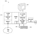
Fig. 2 illustrates an example embodiment of the calculation element system 200 of the payment processes that is used for REV charging and sale article as described herein.Method as herein described can realize by software (for example firmware), hardware or their combination.In example embodiment, method as herein described is embodied as executable program by software, and is moved by the special use such as personal computer, workstation, microcomputer or mainframe computer or universal digital computer.Therefore, system 200 comprises multi-purpose computer 201.
In example embodiment, aspect hardware structure, as shown in Figure 2, computing machine 201 comprises: processor 205; Storer 210 is coupled to memory controller 215; And one or more inputs and/or output (I/O) device 240,245 (or peripheral hardwares), be coupled in communication via local i/o controller 235.I/o controller 235 can be one or more buses or other wired or wireless connection without limitation, and this is known in the art.I/o controller 235 can have the add ons of the communication of realizing, has omitted these add ons for the sake of brevity, for example controller, impact damper (high-speed cache), driver, repeater and receiver.In addition, local interface can comprise that address, control and/or data connect, in order to realize the suitable communication between the said modules.
Software in the storer 210 can comprise one or more stand-alone programs, and wherein each comprises the ordered list for the executable instruction that realizes logic function.In the example of Fig. 2, the software in the storer 210 comprises herein according to the described payment processing method of example embodiment and appropriate operating system (OS) 211.OS 211 controls other computer program, for example execution of payment processing system described herein and method basically, and scheduling, input and output control, file and data management, memory management and Control on Communication and related service are provided.
Payment processing method as herein described can be taked source program, executable program (object code), script or comprise any other entity of pending instruction set.If source program, then program need be via being included in or can not being included in conversions such as compiler in the storer 210, assembler, interpreter, so that correctly operate in conjunction with OS 211.In addition, payment processing method can be written as the object oriented programming languages of the class with data and method or have the process programming language of routine, subroutine and/or function.
In example embodiment, conventional keyboard 250 and mouse 255 can be coupled to i/o controller 235.Other output unit such as I/O device 240,245 can comprise input media, without limitation for example printer, scanner, microphone etc.I/O device 240,245 also can comprise the device that transmits input and output, without limitation for example network interface unit (NIC) or modulator/demodulator (being used for other file of visit, device, system or network), radio frequency (RF) or other transceiver, telephony interface, bridge, router etc.I/O device 240,245 can also comprise automatic vending machine 125.System 200 can also comprise the display controller 225 that is coupled to display 230.In example embodiment, system 200 can also comprise be used to the network interface 260 that is coupled to network 265.Network 265 can be between computing machine 201 and any external server, the client etc. via the IP-based network of communicating by letter of broadband connection.Network 265 transmits and receives data between computing machine 201 and external system.In example embodiment, network 265 can be by the service provider manage by IP network management.Network 265 can be according to wireless mode, for example use wireless protocols and technology such as WiFi, WiMax etc. to realize.Network 265 can also be packet switching network, for example the network environment of LAN (Local Area Network), wide area network, Metropolitan Area Network (MAN), internet network or other similar type.Network 265 can be Fixed Cellular Network, WLAN (wireless local area network) (LAN), wireless wide area network (WAN), personal area network (PAN), VPN (virtual private network) (VPN), Intranet or other suitable network system, and comprises for the equipment that receives and transmit signal.
If computing machine 201 is PC, workstation, intelligent apparatus etc., then the software in the storer 210 also can comprise Basic Input or Output System (BIOS) (BIOS) (omitting for the sake of brevity).BIOS is one group of basic software routine, and they are initialization and testing hardware when starting, and starts OS 211 and is supported in Data transmission between the hardware unit.BIOS is stored among the ROM, makes BIOS to move when computing machine 201 is activated.
When computing machine 201 in when operation, processor 205 is configured to saved software in the run memory 210, data is passed to storer 210 and from storer 210 Data transmission, and the operation of generally controlling computing machine 201 according to software.Payment processing method as herein described and OS 211 in whole or in part but partly read by processor 205 usually, perhaps buffering in processor 205 is moved then.
When system and method as herein described was realized by software, as shown in Figure 2, method can be stored on any computer-readable medium such as memory storage 220, for being used or be used in combination with it by any computer related system or method.
As one skilled in the art will appreciate that aspect of the present invention can be used as system, method or computer program and implements.Correspondingly, aspect of the present invention can take devices at full hardware embodiment, full software embodiment (comprising firmware, resident software, microcode etc.) or in conjunction with the form of the embodiment of software and hardware aspect, they can generally be called " circuit ", " module " or " system " at this paper.In addition, the form of the computer program that comprises on one or more computer-readable mediums can be taked in aspect of the present invention, comprises computer readable program code on it.
Can utilize any combination of one or more computer-readable mediums.Computer-readable medium can be computer-readable signal media or computer-readable recording medium.For example, computer-readable recording medium can be electronics, magnetic, light, electromagnetism, infrared ray or semiconductor system, equipment or device or above-described any appropriate combination without limitation.The more specifically example of computer-readable recording medium (non-exhaustive tabulation) comprises following: the electrical connection with one or more lead, portable computer diskette, hard disk, random-access memory (ram), ROM (read-only memory) (ROM), Erasable Programmable Read Only Memory EPROM (EPROM or flash memory), optical fiber, portable compact disc ROM (read-only memory) (CD-ROM), light storage device, magnetic memory apparatus or above-described any appropriate combination.In the context of this document, computer-readable recording medium can be any tangible medium that can hold or store the program of using or being used in combination with it for instruction execution system, equipment or device.
The computer-readable signal media can comprise the propagation data signal with the computer readable program code that wherein comprises, for example in base band or as the part of carrier wave.This transmitting signal can be taked any of various ways, includes but not limited to electromagnetism, light or their any appropriate combination.The computer-readable signal media can be not as computer-readable recording medium but can transmit, propagates or transmit any computer-readable medium of the program of using or being used in combination with it for instruction execution system, equipment or device.
The program code that comprises on the computer-readable medium can use any suitable medium to transmit, and includes but not limited to wireless, wired, optical cable, RF etc. or above-described any appropriate combination.
The computer program code that is used for the operation of execution aspect of the present invention can be write by any combination of one or more programming languages, comprises Object-Oriented Programming Language and the conventional process programming language such as " C " programming language or similar programming language such as Java, Smaltalk, C++ etc.Program code can be fully in subscriber computer operation, partly capable as the stand alone software contracted affreightment on subscriber computer, and part is partly moved at remote computer or server on remote computer or fully at subscriber computer.Under latter event, remote computer can be by comprising Local Area Network or wide area network (WAN) the network of any kind be connected to subscriber computer, perhaps can proceed to the connection (for example by using ISP's the Internet) of outer computer.
Below with reference to flowchart illustrations and/or block diagram according to method, equipment (system) and the computer program of embodiments of the invention aspect of the present invention is described.Will be understood that each frame of flowchart illustrations and/or block diagram and the combination of the frame in flowchart illustrations and/or the block diagram can realize by computer program instructions.These computer program instructions can be provided for the processor of multi-purpose computer, special purpose computer or other programmable data processing device to produce machine, and the device of the function/action of stipulating for the one or more frames that are implemented in process flow diagram and/or block diagram is created in the feasible instruction that moves via the processor of computing machine or other programmable data processing device.
These computer program instructions also can be stored in the computer-readable medium, they can instruct computing machine, other programmable data processing device or other device to work with ad hoc fashion, make the instruction of storing in the computer-readable medium produce a kind of manufacturing a product, comprising the instruction of the function/action of appointment in one or more frames of realization flow figure and/or block diagram.
Computer program instructions also can be loaded in computing machine, other programmable data processing device or other device, in order to make the sequence of operations step in computing machine, other programmable device or other device operation, thereby produce the computer realization process, make the process that is provided for the function/action of appointment in one or more frames of realization flow figure and/or block diagram in the instruction that computing machine or other programmable device move.
Process flow diagram in the accompanying drawing and block diagram illustrate the framework of the possible realization of system, method and computer program product according to each embodiment of the present invention, functional and operation.In this respect, but each frame representation module, code segment or part in process flow diagram or the block diagram, and it comprises for the one or more executable instructions that realize specified logic function.Shall also be noted that in some alternative realizations, the function shown in the frame can be not according to occurring in sequence shown in the figure.For example, in fact two frames that illustrate continuously can move substantially simultaneously, and perhaps these frames can move sometimes in reverse order, and this depends on related functional.Will notice that also each frame of block diagram and/or flowchart illustrations and the combination of the frame in block diagram and/or the flowchart illustrations can be by carrying out realizing based on the system of specialized hardware or the combination of specialized hardware and computer instruction of specified function or action.
In the example embodiment that payment processing method is realized by hardware, payment processing method as herein described can adopt respectively any or the combination for the well-known following technology of those skilled in the art to realize: have for data-signal is realized the discrete logic circuitry of the logic gate of logic function, the special IC (ASIC) with appropriate combination logic gate, programmable gate array (PGA), field programmable gate array (FPGA) etc.
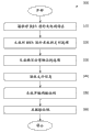
Fig. 3 illustrates as described for the process flow diagram of coordinating the method 300 of payment options between charging station 110 and automatic vending machine 125 according to example embodiment herein.At frame 310, REV interface 111 receives the request that REV 105 is charged from the owner.At frame 320, REV interface 111 generates the payment options that REV 105 is charged.At frame 330, charging station 110 generates option at REV interface 111, and this can carry out via graphical user interface, in order to sell article from vending purchasing.In example embodiment, the owner can also import the request of paying in the duration of charging of charging station 110.At frame 340, REV interface 111 receives payment information from the owner.Payment information such as debit card 130 is for the treatment of the payment for any duration of charging of buying and any sale article of buying.If the owner has selected to buy the option of selling article, then at frame 350, REV interface 111 generates identifying code, buys the sale article in order to finish at automatic vending machine 125, and is as described herein.In addition, identifying code can be taked without limitation to encode such as the receipt of reveal codes or the form factor that has the prize card 135 of value of money.At frame 360, identifying code is related with form factor.
Technique effect comprises the business activity that encouragement and increase are related with charging station and automatic vending machine, in conjunction with business activity, reduces the quantity of debit card transaction and the use of related expense and currency thus.
Though only the embodiment in conjunction with limited quantity describes the present invention in detail, should easy to understand, the present invention is not limited to this class disclosed embodiment.The present invention but can be revised as any amount of variation, change, replacement or the equivalent arrangements of not describing in conjunction with the front, but they are consistent with the spirit and scope of the present invention.In addition, though described each embodiment of the present invention, be appreciated that aspect of the present invention can only comprise the part of described embodiment.Correspondingly, the present invention can not be counted as being subjected to the front and describe restriction, and is only limited by the scope of appended claims.
Description of reference numerals
| 100 | System | 205 | |
| 105 | |
210 | Storer |
| 110 | Charging |
211 | |
| 111 | The |
215 | |
| 112 | The |
220 | |
| 113 | |
225 | |
| 115 | |
230 | |
| 120 | Communication network | 235 | I/ |
| 125 | Automatic |
240 | |
| 126 | |
245 | |
| 130 | |
250 | |
| 135 | The |
255 | Mouse |
| 150 | |
260 | |
| 200 | |
265 | Network |
| 201 | Computing machine | ? | ? |
Claims (20)
1. a rechargeable electric vehicle (REV) charging station comprises:
The REV interface is configured to handle the payment that REV is charged, and handles from the described payment of at least one sale article of vending purchasing; And
Communication interface is coupled to described REV interface in communication, and is configured to communicate with described automatic vending machine.
2. REV charging station as claimed in claim 1 also comprises the power network interface, and described power network interface is coupled to described REV interface in communication, and is configured to receive electric energy and give described REV with described power distribution from power network.
3. REV charging station as claimed in claim 1, wherein, described REV interface also is configured to generate the identifying code that indication receives the described payment of selling article.
4. REV charging station as claimed in claim 3 wherein, is encoded in debit card, prize card and the receipt at least one with described identifying code.
5. REV charging station as claimed in claim 3, wherein, described identifying code via described communication interface with related at least one to sell the debit card of described payment of article related.
6. REV charging station as claimed in claim 3, wherein, described REV interface also is configured to authenticate described identifying code.
7. a rechargeable electric vehicle (REV) charging system comprises:
The REV charging station; And
Automatic vending machine is coupled to described REV charging station in communication, and is configured to provide at least one article in described REV charging station pre-payment.
8. system as claimed in claim 7, wherein, described REV charging station comprises:
The REV interface is configured to handle the payment that REV is charged, and handles from the described payment of at least one article of described vending purchasing; And
Communication interface is coupled to described REV interface in communication, and is configured to communicate with described automatic vending machine.
9. system as claimed in claim 8, wherein, described REV charging station also comprises the power network interface, described power network interface is coupled to described REV interface in communication, and is configured to receive electric energy and give described REV with described power distribution from power network.
10. system as claimed in claim 8, wherein, described REV interface also is configured to generate indication and receives from the identifying code of the described payment of at least one article of described vending purchasing.
11. system as claimed in claim 10 wherein, is encoded in debit card, prize card and the receipt at least one with described identifying code.
12. system as claimed in claim 10, wherein, described identifying code is related with the debit card of the described payment of related at least one article via described communication interface.
13. system as claimed in claim 10, wherein, described REV interface also is configured to authenticate described identifying code.
14. system as claimed in claim 7 also comprises the communication network that is coupling in the communication between described REV charging station and the described automatic vending machine.
15. system as claimed in claim 7 comprises that also the power network that is coupled to described REV charging station in the operation connects.
16. a computer program comprises storage for the nonvolatile computer-readable medium of the instruction that makes computer implemented method, described method comprises:
In rechargeable electric vehicle (REV) interface, receive the request that REV is charged;
Generate the option of buying at least one sale article at described REV interface;
In described REV interface, receive the payment information that at least one sells article; And
Generate identifying code to finish the purchase that at least one sells article at described REV interface.
17. computer program as claimed in claim 16, wherein, described method also is included in and generates the payment options that described REV is charged on the described REV interface.
18. computer program as claimed in claim 17, wherein, the payment options that described REV is charged comprises debit card.
19. computer program as claimed in claim 16, wherein, described method also comprises by computing machine described identifying code is encoded to form factor.
20. computer program as claimed in claim 16, wherein, at least one that described method also comprises the following steps: described identifying code is related with debit card via described computing machine; And by described computing machine described identifying code is coded at least one of prize card and receipt.
Applications Claiming Priority (2)
| Application Number | Priority Date | Filing Date | Title |
|---|---|---|---|
| US13/370,879 US20130207605A1 (en) | 2012-02-10 | 2012-02-10 | Plug-in electric vehicle charging station with vending machine payment options |
| US13/370,879 | 2012-02-10 |
Publications (1)
| Publication Number | Publication Date |
|---|---|
| CN103247109A true CN103247109A (en) | 2013-08-14 |
Family
ID=47709970
Family Applications (1)
| Application Number | Title | Priority Date | Filing Date |
|---|---|---|---|
| CN2013100488557A Pending CN103247109A (en) | 2012-02-10 | 2013-02-07 | Plug-in electric vehicle charging station with vending machine payment options |
Country Status (6)
| Country | Link |
|---|---|
| US (1) | US20130207605A1 (en) |
| EP (1) | EP2626842A1 (en) |
| JP (1) | JP2013164844A (en) |
| KR (1) | KR20130092478A (en) |
| CN (1) | CN103247109A (en) |
| AU (1) | AU2013200618A1 (en) |
Cited By (3)
| Publication number | Priority date | Publication date | Assignee | Title |
|---|---|---|---|---|
| CN105654285A (en) * | 2015-12-30 | 2016-06-08 | 中山市粤盛电气设备有限公司 | Intelligent all-purpose card payment system |
| CN106183843A (en) * | 2015-05-29 | 2016-12-07 | 通用汽车环球科技运作有限责任公司 | Electric vehicle charging station |
| CN111497663A (en) * | 2019-01-31 | 2020-08-07 | 本田技研工业株式会社 | Charging management device, charging management method, and storage medium |
Families Citing this family (15)
| Publication number | Priority date | Publication date | Assignee | Title |
|---|---|---|---|---|
| US9371007B1 (en) * | 2011-04-22 | 2016-06-21 | Angel A. Penilla | Methods and systems for automatic electric vehicle identification and charging via wireless charging pads |
| ES2701745T3 (en) | 2011-07-26 | 2019-02-25 | Gogoro Inc | Apparatus, method and article for the redistribution of energy storage devices, such as batteries, between collection, loading and distribution machines |
| WO2013016545A2 (en) | 2011-07-26 | 2013-01-31 | Gogoro, Inc. | Apparatus, method and article for providing vehicle diagnostic data |
| US10186094B2 (en) | 2011-07-26 | 2019-01-22 | Gogoro Inc. | Apparatus, method and article for providing locations of power storage device collection, charging and distribution machines |
| WO2013016564A2 (en) | 2011-07-26 | 2013-01-31 | Gogoro, Inc. | Apparatus, method and article for reserving power storage devices at reserving power storage device collection, charging and distribution machines |
| JP2014529118A (en) | 2011-07-26 | 2014-10-30 | ゴゴロ インク | Apparatus, method and article for providing information relating to the availability of a power storage device in a power storage device collection, charging and distribution machine |
| JP6462655B2 (en) | 2013-03-15 | 2019-01-30 | ゴゴロ インク | Modular system for collection and distribution of electricity storage devices |
| US9715682B2 (en) * | 2013-10-29 | 2017-07-25 | Wal-Mart Stores, Inc. | System and method for dispensing and purchasing fuel |
| KR101562596B1 (en) * | 2014-05-08 | 2015-10-23 | 엘에스산전 주식회사 | Prepayment meter |
| EP3180821B1 (en) | 2014-08-11 | 2019-02-27 | Gogoro Inc. | Multidirectional electrical connector and plug |
| ES2942882T3 (en) * | 2014-09-04 | 2023-06-07 | Gogoro Inc | Apparatus, system and method of sale, charging and bidirectional distribution of electrical energy storage devices |
| WO2020055770A1 (en) * | 2018-09-11 | 2020-03-19 | Zume, Inc. | Automated food preparation coordination with customer activity |
| JP2020086531A (en) * | 2018-11-15 | 2020-06-04 | トヨタ自動車株式会社 | Vehicle and settlement system |
| US20220083999A1 (en) * | 2020-09-17 | 2022-03-17 | R & L Connections | Campsite utility access pedestal |
| DE102020128965A1 (en) | 2020-11-03 | 2022-05-05 | Westenergie Ag | Computer program product for an electrical charging station and computer-implemented method for electrically charging a traction battery of a vehicle |
Citations (5)
| Publication number | Priority date | Publication date | Assignee | Title |
|---|---|---|---|---|
| US4111282A (en) * | 1976-08-23 | 1978-09-05 | Vayda Jr Michael Mark | Single-stop shopping facility and method |
| US5450938A (en) * | 1994-05-02 | 1995-09-19 | Xcp, Inc. | Card or cash actuated vending machine assembly |
| US6193154B1 (en) * | 1994-08-24 | 2001-02-27 | The Coca-Cola Company | Method and apparatus for vending goods in conjunction with a credit card accepting fuel dispensing pump |
| EP1315128A1 (en) * | 2001-11-23 | 2003-05-28 | Scheidt & Bachmann Gmbh | Method for the use of automatic systems |
| US20100191585A1 (en) * | 2009-01-23 | 2010-07-29 | Recharge Systems Llc | Metered recharging system |
Family Cites Families (9)
| Publication number | Priority date | Publication date | Assignee | Title |
|---|---|---|---|---|
| US6845907B1 (en) * | 1998-11-13 | 2005-01-25 | Diebold, Incorporated | Cash delivery apparatus for motor fuel dispenser or other self service facility |
| EP1281137B1 (en) * | 2000-05-09 | 2003-09-10 | Swisscom Mobile AG | Transaction method and selling system |
| DE50114738D1 (en) * | 2000-08-04 | 2009-04-16 | Harting Systems Gmbh & Co Kg | Method for secure data transmission when selling goods |
| EP1315129B1 (en) * | 2001-11-23 | 2010-02-24 | Scheidt & Bachmann Gmbh | Method for the use of automatic systems |
| NO318746B1 (en) * | 2002-02-22 | 2005-05-02 | Vensafe Asa | Consumer goods sales system |
| US20040077408A1 (en) * | 2002-10-21 | 2004-04-22 | D'amico Michael H. | Gaming award method and apparatus |
| JP5534347B2 (en) * | 2010-01-06 | 2014-06-25 | ビーエルデーオリエンタル株式会社 | CHARGE CONTROL DEVICE AND CHARGE SYSTEM USING THE CHARGE CONTROL DEVICE |
| ES2346283B1 (en) * | 2010-03-03 | 2011-09-05 | Miguel Salamanques Claver | CONTROL SYSTEM AND MANAGEMENT OF ENERGY RECHARGE, COMMUNICATION AND LIGHTING. |
| JP5623832B2 (en) * | 2010-09-03 | 2014-11-12 | 日本たばこ産業株式会社 | Product delivery device, product delivery system, product delivery method and program |
-
2012
- 2012-02-10 US US13/370,879 patent/US20130207605A1/en not_active Abandoned
-
2013
- 2013-02-04 AU AU2013200618A patent/AU2013200618A1/en not_active Abandoned
- 2013-02-05 JP JP2013020007A patent/JP2013164844A/en active Pending
- 2013-02-07 CN CN2013100488557A patent/CN103247109A/en active Pending
- 2013-02-07 KR KR1020130013837A patent/KR20130092478A/en not_active Application Discontinuation
- 2013-02-08 EP EP13154575.8A patent/EP2626842A1/en not_active Withdrawn
Patent Citations (5)
| Publication number | Priority date | Publication date | Assignee | Title |
|---|---|---|---|---|
| US4111282A (en) * | 1976-08-23 | 1978-09-05 | Vayda Jr Michael Mark | Single-stop shopping facility and method |
| US5450938A (en) * | 1994-05-02 | 1995-09-19 | Xcp, Inc. | Card or cash actuated vending machine assembly |
| US6193154B1 (en) * | 1994-08-24 | 2001-02-27 | The Coca-Cola Company | Method and apparatus for vending goods in conjunction with a credit card accepting fuel dispensing pump |
| EP1315128A1 (en) * | 2001-11-23 | 2003-05-28 | Scheidt & Bachmann Gmbh | Method for the use of automatic systems |
| US20100191585A1 (en) * | 2009-01-23 | 2010-07-29 | Recharge Systems Llc | Metered recharging system |
Cited By (4)
| Publication number | Priority date | Publication date | Assignee | Title |
|---|---|---|---|---|
| CN106183843A (en) * | 2015-05-29 | 2016-12-07 | 通用汽车环球科技运作有限责任公司 | Electric vehicle charging station |
| CN105654285A (en) * | 2015-12-30 | 2016-06-08 | 中山市粤盛电气设备有限公司 | Intelligent all-purpose card payment system |
| CN111497663A (en) * | 2019-01-31 | 2020-08-07 | 本田技研工业株式会社 | Charging management device, charging management method, and storage medium |
| CN111497663B (en) * | 2019-01-31 | 2023-08-22 | 本田技研工业株式会社 | Charging management device, charging management method, and storage medium |
Also Published As
| Publication number | Publication date |
|---|---|
| AU2013200618A1 (en) | 2013-08-29 |
| KR20130092478A (en) | 2013-08-20 |
| JP2013164844A (en) | 2013-08-22 |
| US20130207605A1 (en) | 2013-08-15 |
| EP2626842A1 (en) | 2013-08-14 |
Similar Documents
| Publication | Publication Date | Title |
|---|---|---|
| CN103247109A (en) | Plug-in electric vehicle charging station with vending machine payment options | |
| US8676636B2 (en) | System for managing electric energy grid-vehicle exchange devices | |
| TWI590556B (en) | Physical and virtual identification in a wireless power network and relevant wireless charging system, storage medium and method therefore | |
| US8725551B2 (en) | Smart electric vehicle interface for managing post-charge information exchange and analysis | |
| JP5948674B2 (en) | Car soliciting device, in-vehicle terminal device, car soliciting method and program thereof | |
| US20120197693A1 (en) | Electricity transfer system network and related methods | |
| US20100191585A1 (en) | Metered recharging system | |
| US20090313104A1 (en) | Managing Incentives for Electric Vehicle Charging Transactions | |
| JP2012513636A (en) | System and method for roaming billing for electric vehicles | |
| US20120116955A1 (en) | Charging purchases to utility accounts | |
| US20120116575A1 (en) | Combination electric vehicle charger and point of sale device | |
| WO2008115718A1 (en) | A method and system for the authorization of and payment for electric charging of vehicles | |
| AU2012202933A1 (en) | Systems and methods for reservations of charging stations for electric vehicles | |
| US20120296794A1 (en) | Systems and Methods for Auctioning Charging Times for Electric Vehicles | |
| CN105162263A (en) | Metered delivery of wireless power | |
| JP6383249B2 (en) | Parking lot electronic payment system, parking lot electronic payment method, program | |
| US11816660B1 (en) | Methods and systems for making a pre-payment from a vehicle | |
| JP2012513637A (en) | System and method for electric vehicle charging supported by a wireless communication link | |
| CN107274160A (en) | Wireless payment transaction in vehicle environmental | |
| WO2011115182A1 (en) | Charging fee billing method, charging fee billing system, charging stand device, automobile-mounted charging device | |
| CN103635815A (en) | System and method for use in delivering energy to an electrically powered vehicle within a parking area | |
| US20150228017A1 (en) | Methods and systems for approval of credit | |
| JP2013178594A (en) | Power supplying system for electric vehicle | |
| Droździel et al. | The application of the progressive decision-making methods in the electronic payment system in public transport | |
| CN103700188A (en) | Method for implementing self-service payment on water, electricity and gas and storing purchasing fee-based information in self-service manner |
Legal Events
| Date | Code | Title | Description |
|---|---|---|---|
| C06 | Publication | ||
| PB01 | Publication | ||
| C10 | Entry into substantive examination | ||
| SE01 | Entry into force of request for substantive examination | ||
| WD01 | Invention patent application deemed withdrawn after publication | ||
| WD01 | Invention patent application deemed withdrawn after publication |
Application publication date: 20130814 |