CN102948260A - Illumination apparatus methods and systems - Google Patents
Illumination apparatus methods and systems Download PDFInfo
- Publication number
- CN102948260A CN102948260A CN2011800286395A CN201180028639A CN102948260A CN 102948260 A CN102948260 A CN 102948260A CN 2011800286395 A CN2011800286395 A CN 2011800286395A CN 201180028639 A CN201180028639 A CN 201180028639A CN 102948260 A CN102948260 A CN 102948260A
- Authority
- CN
- China
- Prior art keywords
- illumination
- controller
- light
- signal
- light source
- Prior art date
- Legal status (The legal status is an assumption and is not a legal conclusion. Google has not performed a legal analysis and makes no representation as to the accuracy of the status listed.)
- Pending
Links
- 238000005286 illumination Methods 0.000 title claims abstract description 53
- 238000000034 method Methods 0.000 title claims abstract description 26
- 230000033001 locomotion Effects 0.000 claims abstract description 16
- 230000000694 effects Effects 0.000 claims description 19
- 238000001514 detection method Methods 0.000 claims description 16
- 238000000926 separation method Methods 0.000 claims 1
- 230000004044 response Effects 0.000 abstract description 15
- 238000004891 communication Methods 0.000 abstract description 13
- 238000006243 chemical reaction Methods 0.000 description 20
- 230000008859 change Effects 0.000 description 7
- 230000008569 process Effects 0.000 description 4
- 230000005855 radiation Effects 0.000 description 4
- 230000000007 visual effect Effects 0.000 description 4
- 230000004913 activation Effects 0.000 description 3
- 238000010276 construction Methods 0.000 description 3
- 238000009434 installation Methods 0.000 description 3
- 238000002310 reflectometry Methods 0.000 description 3
- 230000003213 activating effect Effects 0.000 description 2
- 230000005540 biological transmission Effects 0.000 description 2
- 230000000739 chaotic effect Effects 0.000 description 2
- 230000002950 deficient Effects 0.000 description 2
- 238000010586 diagram Methods 0.000 description 2
- 238000005516 engineering process Methods 0.000 description 2
- 239000000463 material Substances 0.000 description 2
- 238000005457 optimization Methods 0.000 description 2
- 239000011148 porous material Substances 0.000 description 2
- 238000013459 approach Methods 0.000 description 1
- 230000002349 favourable effect Effects 0.000 description 1
- 230000037361 pathway Effects 0.000 description 1
- 238000012545 processing Methods 0.000 description 1
- 238000012360 testing method Methods 0.000 description 1
Images


Classifications
-
- G—PHYSICS
- G08—SIGNALLING
- G08C—TRANSMISSION SYSTEMS FOR MEASURED VALUES, CONTROL OR SIMILAR SIGNALS
- G08C23/00—Non-electrical signal transmission systems, e.g. optical systems
- G08C23/04—Non-electrical signal transmission systems, e.g. optical systems using light waves, e.g. infrared
-
- H—ELECTRICITY
- H05—ELECTRIC TECHNIQUES NOT OTHERWISE PROVIDED FOR
- H05B—ELECTRIC HEATING; ELECTRIC LIGHT SOURCES NOT OTHERWISE PROVIDED FOR; CIRCUIT ARRANGEMENTS FOR ELECTRIC LIGHT SOURCES, IN GENERAL
- H05B47/00—Circuit arrangements for operating light sources in general, i.e. where the type of light source is not relevant
- H05B47/10—Controlling the light source
- H05B47/105—Controlling the light source in response to determined parameters
- H05B47/11—Controlling the light source in response to determined parameters by determining the brightness or colour temperature of ambient light
-
- H—ELECTRICITY
- H05—ELECTRIC TECHNIQUES NOT OTHERWISE PROVIDED FOR
- H05B—ELECTRIC HEATING; ELECTRIC LIGHT SOURCES NOT OTHERWISE PROVIDED FOR; CIRCUIT ARRANGEMENTS FOR ELECTRIC LIGHT SOURCES, IN GENERAL
- H05B47/00—Circuit arrangements for operating light sources in general, i.e. where the type of light source is not relevant
- H05B47/10—Controlling the light source
- H05B47/105—Controlling the light source in response to determined parameters
- H05B47/115—Controlling the light source in response to determined parameters by determining the presence or movement of objects or living beings
-
- H—ELECTRICITY
- H05—ELECTRIC TECHNIQUES NOT OTHERWISE PROVIDED FOR
- H05B—ELECTRIC HEATING; ELECTRIC LIGHT SOURCES NOT OTHERWISE PROVIDED FOR; CIRCUIT ARRANGEMENTS FOR ELECTRIC LIGHT SOURCES, IN GENERAL
- H05B47/00—Circuit arrangements for operating light sources in general, i.e. where the type of light source is not relevant
- H05B47/10—Controlling the light source
- H05B47/175—Controlling the light source by remote control
- H05B47/19—Controlling the light source by remote control via wireless transmission
-
- G—PHYSICS
- G08—SIGNALLING
- G08C—TRANSMISSION SYSTEMS FOR MEASURED VALUES, CONTROL OR SIMILAR SIGNALS
- G08C2201/00—Transmission systems of control signals via wireless link
- G08C2201/50—Receiving or transmitting feedback, e.g. replies, status updates, acknowledgements, from the controlled devices
- G08C2201/51—Remote controlling of devices based on replies, status thereof
-
- H—ELECTRICITY
- H05—ELECTRIC TECHNIQUES NOT OTHERWISE PROVIDED FOR
- H05B—ELECTRIC HEATING; ELECTRIC LIGHT SOURCES NOT OTHERWISE PROVIDED FOR; CIRCUIT ARRANGEMENTS FOR ELECTRIC LIGHT SOURCES, IN GENERAL
- H05B47/00—Circuit arrangements for operating light sources in general, i.e. where the type of light source is not relevant
- H05B47/10—Controlling the light source
- H05B47/105—Controlling the light source in response to determined parameters
-
- H—ELECTRICITY
- H05—ELECTRIC TECHNIQUES NOT OTHERWISE PROVIDED FOR
- H05B—ELECTRIC HEATING; ELECTRIC LIGHT SOURCES NOT OTHERWISE PROVIDED FOR; CIRCUIT ARRANGEMENTS FOR ELECTRIC LIGHT SOURCES, IN GENERAL
- H05B47/00—Circuit arrangements for operating light sources in general, i.e. where the type of light source is not relevant
- H05B47/10—Controlling the light source
- H05B47/175—Controlling the light source by remote control
- H05B47/19—Controlling the light source by remote control via wireless transmission
- H05B47/195—Controlling the light source by remote control via wireless transmission the transmission using visible or infrared light
-
- Y—GENERAL TAGGING OF NEW TECHNOLOGICAL DEVELOPMENTS; GENERAL TAGGING OF CROSS-SECTIONAL TECHNOLOGIES SPANNING OVER SEVERAL SECTIONS OF THE IPC; TECHNICAL SUBJECTS COVERED BY FORMER USPC CROSS-REFERENCE ART COLLECTIONS [XRACs] AND DIGESTS
- Y02—TECHNOLOGIES OR APPLICATIONS FOR MITIGATION OR ADAPTATION AGAINST CLIMATE CHANGE
- Y02B—CLIMATE CHANGE MITIGATION TECHNOLOGIES RELATED TO BUILDINGS, e.g. HOUSING, HOUSE APPLIANCES OR RELATED END-USER APPLICATIONS
- Y02B20/00—Energy efficient lighting technologies, e.g. halogen lamps or gas discharge lamps
- Y02B20/40—Control techniques providing energy savings, e.g. smart controller or presence detection
Abstract
The present invention provides apparatus and methods for controlling the illumination throughout an area where even and constant lighting is not required. The invention includes one or more light sources, such as luminaires, the status of which is controlled by a controller responsive to a sensor for detecting a parameter of interest. Preferably the sensor detects motion of a subject moving through the area of controlled illumination. Each independent controller may receive and transmit signals indicative of the status of one or more nearby light source for determining and controlling the lighting status of the light source with which it is in controlling communication. The determining by the controller is preferably carried out by a programmed microprocessor. The communication between controllers may be wireless. The signals communicated among controllers may be hierarchical for determining whether a response is required and what the response might be.
Description
Related application
The application requires in priority and the rights and interests of the Australian provisional application No.2010901746 of submission on April 26th, 2010.
Technical field
The present invention relates to electric control system, and specifically relate to illumination control.
Background technology
Be in charge of heavy construction for example the common issue with that exists of the electric control system of factory, warehouse and office be energy loss.Hope is guaranteeing that normal activity can be few or when not carrying out in the noisy situation an as much as possible energy saving.Effective control of illumination is architectural control person's common objective.
The various trials of controlling illumination based on the existence of personnel in the given area or activity have been made.In simplified example, personnel manually open and close illumination in the zone that they enter and leave.This has following shortcoming: normal activity can may even cause danger by this process interruption and this, if the people who especially discusses is processing the material of potentially dangerous, but must put down and pick up this material in order to turn on light and turn off the light.
In the well-known solution that control is thrown light under situation for example described above, may need the people to activate and cause lamp to open also the then delay switch of autoshutdown after the scheduled time, the described time is enough to make the people to carry out needed activity and leaves the field of illumination.。This has following shortcoming: if the people need to be than the pre-programmed more time of turn-on time, may in the situation that there is not light to be left, there be danger in they so.
As by Szuba in U.S. Patent No. 5,220, another common pathway disclosed in 250 is whether to have to activate lamp with transducer based on the testing staff.This transducer can be a type in each several type that activated by the movement of personnel in the specific region (for example microwave remote sensor, Passive Infrared Sensor or ultrasonic sensor).These transducers can append to independent light fixture maybe can separate placement, so that detection is mobile and activate independent light fixture, or otherwise activates a plurality of light fixtures of expression field of illumination (for example part in warehouse).
Above-mentioned detection approach has a lot of main defectives.Therein in the situation of each light fixture by the first example of its oneself transducer control, although problem is unusual Energy Efficient, illuminated zone is too small for normal mankind's activity, and is undesirable therefore.In the second situation of several light fixtures of sensor activation, light fixture must be accessed the zone by sensor activation therein.The description in this zone is determined during initial installation and commissioning, and cannot usefully relate to the change needs of illumination when changing after a period of time in the border of the activity of being engaged in by personnel.For example, the reorientation meeting of assembly line causes it that two surrounds are overlapping, so that the efficient of impossible optimization illuminator.
In the more recent time, had the under construction trial of optimization illumination of computerization building management system of using as being instructed by Huizenga (U.S. Patent No. 7,623,042).This system can receive input from the transducer of placing under construction, and the actuating logic operation is in order to switch on and off facility, for example for warm lighting installation.In the case, system has following shortcoming: the high cost that the needed Radio Link of logical connectivity is provided between light fixture, transducer and control unit.For the system that the control of wherein sensitive information and electric power provides via circuit, the cost that is associated with the installation of described wiring is very high.At all in this case, the cost of control unit and the transducer that separates has further increased cost burden.Further shortcoming is identical with other center systems, and light fixture accesses the zone between trial run period.These zones are normally large as much as possible, because this minimizes wiring cost and interface cost.As a result, the granularity of illumination being controlled is limited to the restriction energy and uses the size in the zone of the scope that can be optimised.
A very general defective of automatic illuminating control is when activity stops, and usually after further delay period, light fixture is closed.This has produced very chaotic effect to the personnel that work nearby.The zone that the people works just therein although can throw light on well, the flip-flop of ambient illumination can cause chaotic and negative safety or productivity ratio effect.Needed is for than current known equipment, method and system more efficiently and cost effectively throw light on improved equipment, the method and system of specified region.
Summary of the invention
The invention provides equipment, method and system for the control area illumination.An object of the present invention is when only occupied in the zone or the other times when needs throw light on provide illumination in this zone, and the illumination that provides of control.In one aspect, the invention provides a kind of equipment, this equipment by for detection of a transducer, limited range sender unit of the variation of a parameter of expression activity interested, be used for receiving a checkout gear, a controller and a light source of transmitting and consist of.Preferably, this activity interested is human the existence.Preferably, this transducer is a motion detection apparatus.Alternately, this transducer can detect radiation preferably, and this light source is to be known in the art by a shell, light source, power supply, control device and other an elements light fixture consisting of of light diffuser, timer, sensor for example.Light fixture can comprise a plurality of transducers for a plurality of parameters of sensing.This sender unit can send and detection signal.This signal can be encoded.
In another aspect, the invention provides a kind of method of optionally being thrown light in the zone of passing with room and time.The method may further comprise the steps: sensing represent one first variations of a human parameter that exists, the first area of throwing light on, with illumination condition be transmitted at least one second area from a first area, according to preassigned determine whether to throw light at least one second area and according to this preassigned at least one second area that throws light on.Preferably, the sensing step detects motion.Alternately, the sensing step can detect thermal radiation, temperature or another parameters of interest.The method can comprise one second step that changes determining the human parameter that exists of expression.The method can comprise the step that determines whether according to the preassigned lighting-off.The method can comprise make cause some the zone illuminated and some regional not illuminated a plurality of definite steps.Preferably, determining step is carried out by a controller.Preferably, this controller comprises and being programmed in order to carry out a microprocessor of determining step.Preferably, the sensing step is carried out by a signal supervisory instrument.Preferably, step of transmitting is carried out by infrared broadcasting.The method can comprise should the zone with electric source lighting.Preferably, this light source is light fixture.Step of transmitting can comprise and transmitting.Preferably, signal is encoded.Can be according to a classification schemes with this Signal coding classification.This classification schemes can comprise at least one class categories or grade.Preferably, this classification schemes is made of a plurality of classifications or grade.A hierarchical relationship of the signal that classification can be launched by a plurality of controllers defines.Most preferably, this hierarchical relationship is associated with the reception controller.Most preferably, this hierarchical relationship is made of a plurality of grades.
The present invention includes an illuminator that is used to some zone that illumination is provided, wherein this system is made of a plurality of light sources, and these a plurality of light sources can be operated independently and can be controlled by a controller that communicates with or a plurality of controller.
Description of drawings
Fig. 1 shows a kind of light-source system of arranging in illuminator according to the present invention, it shows makes a plurality of light fixtures.
Fig. 2 shows the block diagram of illuminator, this block diagram show the basic element of character and between relation.
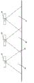
Fig. 3 show for communication range between the light source of restriction illuminator in case restriction in abutting connection with the preferred embodiment of the scope between the light fixture.
Fig. 4 shows the projected area of light-emitting diode in illuminator and the overlay region of the visual field of infrared sensor.
Fig. 5 shows the flow chart of the algorithm of implementing in each light source that is described in the illuminator.
Embodiment
The present invention includes a kind of method and system of illumination for the control illuminator, wherein the present invention is made of checkout gear, controller and light source for detection of at least one transducer of parameter, communicator, the described broadcast communication of reception.Preferably, communicator emission and/or reception limited range signal.Preferably, light source is made of known light fixture in the field of illumination.Yet, can use other light sources.Preferred embodiment described herein comprises it being the light source of light fixture, but the light source that will understand any appropriate can be incorporated embodiment of the present invention into.Preferably, transducer is motion detection sensor.Yet, can use for example radiation transducer of other indicating devices.Preferably, motion detection apparatus detects human motion.The communicator emission also receives signal.Preferably, signal is classified or encodes.Preferably, this classification comprises a plurality of classifications.Preferably, this classification is named a series of grades.Preferably, this grade represents to be used for numerical value rank relatively by receiving controller.In every respect, the present invention can provide the illumination that navigates to the zone that wherein has activity interested or adjacency activity interested, depends on the character of institute's expected activity in this zone.When the motion detection apparatus that is associated with light fixture detected existing of activity, it provided the signal that is input to controller.Because the activation of this input signal, so controller can provide output signal in order to activate the interior light source of light fixture.Therefore institute's activating light source provides illumination for being engaged in movable people.Equally, in response to input signal, controller can activate short-range communication means so that broadcast singal.Preferably, be the one-level broadcast singal with this Signal coding.The present invention includes the multiple combination of light source, each combination can or can not comprise controller.For example, can be by two light sources of shared control unit control in order to throw light on demand and when needed larger zone.Similarly, can control a plurality of light sources by single controller.Embodiment of the present invention comprise with a plurality of controllers and configure and control so that by a plurality of light sources of the illumination of hope control specific region.This light source needs not be identical, and can be the combination of various light sources type.
This signal can receive by incorporating light fixture into or controlling the communicator of communicating by letter with near light fixture, and each in this light fixture will be therefore connected the light source of this light fixture according to programmable controller, and emission is encoded to the signal of class B broadcasting signal.Owing to receiving this second signal, the controller that therefore is used for also not receiving near the light fixture of one stage signal can be connected the light source of this light fixture and can cause the emission of three grades of signals, etc.Can with the control light source for example the controller programming of light fixture in order to only in response to the narrow level of signal of signal emission and with the particular transmission ordinal response, therefore limited in response to the zone of activity detection event by the illumination of activity-stimulat interested.The controller of for example, communicating by letter with light fixture (this controller is programmed so that in response to the signal that is categorized as the firsts and seconds signal) can be programmed in order to only launch more advanced signal in response to one stage signal.If receive second signal by the controller that is used for light fixture, so its not broadcast singal as response.This has the effect of forcing the illumination border to be limited to the light fixture that receives the class B broadcasting signal.Because each reflector has limited range, it therefore is the farthest activating light source that class of emission and the combination of the limited distance scope of broadcast singal of one-level or second signal will be limited to naturally apart from the distance of the former motion detection apparatus that is associated with light source the former activity interested of distance.
Can be with the programming of each light fixture in order to launch certain intensity level during the arbitrary signal in receiving motor message, one stage signal, second signal etc.For example, system can be made of motion level signal and one stage signal simply.System will only be difficult in response to motor message or from the signal that is close to light fixture in the case.No matter specific light fixture is directly in abutting connection with the light fixture of " motion " pattern or apart from this motion light fixture any distance of sensing, all only receives and launches one stage signal.In the case, preferably with level setting 1, light fixture 1 grade of signal of emission when receiving object and have signal or 1 grade of signal wherein.
The method can also be included in after received signal stops, and illumination rests on a grade or the dead time able to programme of the grade that reduces subsequently.
According to above description, obviously can will be to its each behavior able to programme that responds the restriction of the grade that transmits and be used for level of signal to each light fixture by using, to for the controller programming of each light fixture, control the scope of institute field of illumination.For example, wherein light fixture only in response to the system of one stage signal will less than wherein with the light fixture programming so as in response to until two, three, other similar systems of the signal of level Four etc.
Referring now to Fig. 1, exemplary of the present invention is described.Detected the existence of object (1) by the first sensor in the first light fixture (2).The controller of communicating by letter with the described first sensor in described the first light fixture (2) is connected the light source of this first light fixture, and emission is by the one-level broadcast singal (3) of the detection of the checkout gear near the secondary light fixture (4 and 5).Can be for the arbitrarily general available receiver that transmits with understanding checkout gear.The controller that is associated with second, third or near light fixture (4 and 5) is connected the light source of this light fixture, and emission is by near light fixture other (7 and 8) and by the second signal (6) that originates from or the first light fixture (2) detects.Should originate from or the first light fixture programming in order to when it has launched the lower grade signal, do not respond this signal.Controller in the light fixture that detects class B broadcasting signal (6) (7 and 8) is connected the light source of these light fixtures.Since with the programming of all light fixtures in order to only transmit based on receiving one stage signal, so light fixture 7 and 8 broadcast singal not is not so there is more light fixture to be activated.
The many possible variant that understanding is had the step of method described above.In the variant of above method, light fixture can be programmed, if so that this light fixture does not also have to launch the signal of lower or equal grade, then have nothing to do and launch the next stage signal in the received signal value class.For example, light fixture can initially be idle, does not receive signal in a period of time.If it receives N level signal (wherein N is arbitrary integer), then it will launch N+1 level signal.The behavior allows to form can the advantageous alternately light pattern of tool.For example, light fixture can be following in response to signal.
If light fixture is idle (not receiving signal in a period of time) and the first received signal is N level (wherein N is 1 or 2), then controller connect this light fixture light source to full brightness, and light fixture emission N+1 level signal.
If light fixture is idle and the first received signal is M level (wherein M is 3 or 4), this light fixture can be connected its light source to half intensity and launch M+1 level signal so.
Level of signal increases with distance, and in the situation that is not limited in the reflector communication distance all light fixtures and launches.The controller of some light fixtures can be programmed so that in response to the arbitrary number of level signal.If wish illumination passage, entrance and exit corridor, urgent inlet point etc. in the optional position in general area whenever any people, emergency lighting and the wherein effective location illumination in movable occurent zone are provided, this is favourable so.This light fixture is incorporated on the controller most convenient ground that is used for light fixture into.Yet, can separate from it understanding the controller of not incorporating light fixture into, but communicate with.Further, controller can and need the needs in illuminated zone to control more than a light fixture by system dimension.
The most advantageously, equipment of the present invention is preferably incorporated in the emission that is associated with light fixture and the short-distance wireless signal between the checkout gear is communicated by letter.In the situation that wireless transmission, emission and checkout gear can be any device that can transmit via limited distance.The common unit that is used for short-range communication comprises infrared link, ultrasonic link, low-power radio link etc.Yet category of the present invention also is included in the signal emission between the checkout gear that is hard-wired.Present invention resides in the device of modulation main light source on the light fixture.For example, if the known fluorescent tube of those of ordinary skill in the art is by can be rapidly driving in response to the drive circuit of the appropriate designs of its brightness settings circuit, then very possible is the light output of this fluorescent tube of modulation.
The description of preferred embodiment is provided now.Referring to Fig. 2, the present invention preferably is embodied as a light fixture (31) that is made of a shell, this shell contains a preferably light source of a fluorescent tube (32), this light source correctly drives this fluorescent tube with an electric ballast (32a) at a plurality of luminosity classes of selecting, a controller (3), motion detector (34) based on the passive infrared technology, first photoelectric detector (35) for detection of ambient light level, can detect the radiation in the near infrared region in order to receive second photoelectric detector (36) of infrared communication signal, and a light-emitting diode (37), its dominant wavelength in the near infrared region so that emission infrared communication signal.
Described controller is controlled described electric ballast is adjusted described light source on demand according to the step of the algorithm of describing in Fig. 5 based on surround lighting, the motion that detects, incident infrared communication and time luminosity.Therefore, described controller is obtained input signal from the first and second photoelectric detectors and motion detector, and provides output in order to control described electric ballast and drive described light-emitting diode.
Referring to Fig. 2, an aanalogvoltage that is preferably provided by controller (33) to this control signal of electric ballast (32a) at control line (39), although can adopt in several control signal patterns any one, for example aanalogvoltage, current cycle, digital pulse width modulation signal, pulse position modulation and serial data communication.
Referring to Fig. 3, the aspect of the present invention that relates to the scope that limits infrared communication is described now.In preferred embodiments, by limit the communication range between the light fixture with physical pore size.In an embodiment of physical pore size, the mask of associated shape (13) can be provided by the zone of the illumination that is provided by infrarede emitting diode (11).In another embodiment, the mask of associated shape (14) can limit the visual field of infrared photodiode (12).Can use other embodiments in aperture with understanding.
Fig. 4 shows the overlay region (20) with the projected area (25) of launching the light-emitting diode that light fixture (22) is associated and the visual field (26) that is associated with receiving light (23).Therefore visible receiving light (23) can receive infrared emission from emission light fixture (22), and farther light fixture (24) cannot.
The method preferably includes for setting baseline value in order to dynamically control the calibration process of the operation of light fixture at particular system.In the first step of calibration process, calibrated timer begins a calibration cycle.When calibration cycle expires, " calibration " signal that emission has been encoded.From the surface for example the calibrating signal that reflects of floor or other reflectings surface sensed to.The reflectivity of the power grade presentation surface that receives, this reflectivity are important for the Optimum Operation of illuminator.Preferably, the power grade of institute's sensing is measured, and and be illustrated in abutting connection with or near light fixture between transmit needed abundance but the threshold level of the power exceeded relatively.According to system's needs, can the Modulating Power grade in order to only transmit in abutting connection with light fixture to one or more, maybe can be for scope Modulating Power grade so as to comprise one or more near light fixtures and one or more in abutting connection with light fixture.Then can select the power stage transmit with respect to threshold value based on the power grade that receives.Timer can be retransmitted and send, and a unit is then in new power grade emission.Preferably, this Period Process repetition is in order to dynamically adjust for the variation of the reflectivity on the surface in the surround.
Referring to Fig. 5, the following exemplary implementation that is described in the algorithm in each light source.
The flow chart of Fig. 5 shows the method that is made of several steps that relate to a plurality of states, this for example standby of a plurality of states (Standby) (41) and have object (SubjectPresent) (43), and definition is used for being transformed into the standard of leaving of another state and several conversions of Engage of standard from a state, for example be the tStandby (57) of conversion of Standby (41) that gets the hang of, and be the tSubjectPresent (42) of conversion of SubjectPresent (43) of getting the hang of.Each state only has one and enters conversion, and has potentially a plurality of conversions of leaving.Each state also has the digital state variable, be defined in the light output stage in this state illumination (Illumination) (61) if, definition have timer then this timer and then enter timer (Timer) (62) and the Transmit level of signal (63) that given state begins countdown, if the signal that its definition has signal broadcasting then outwards to send to contiguous light source when at given state is broadcasted grade.It is configurable that these state variables can maybe can be can't help the user, maybe can be fixed value.
The following instance of a series of conversions between the state as in the illuminator that goes out as shown in fig. 1, act on from the single light source visual angle about can how to be implemented in the explanation of the step of the algorithm shown in Fig. 5.From Standby (41), light source can enter three free position in the state: SubjectPresent (42), grade 1 activates (Level1 Active) (49) or grade 2 activates (Level2Active) (54), the state that depends on these three conversion parameters, sensing (58), the registration of reception signal (59) and timer state (60).For example, if sense object, so just the parameter at sensing will become " SubjectPresent ", and will satisfy conversion tSubjectPresent (42), and the light source SubjectPresent (43) that will get the hang of.In the case, light source is configured to exist illumination (PresenceLux) (61) with its Illumination grade.Because object exists, therefore under this state, will not start timer (62), and conversion will not occur until object becomes does not exist.Under described SubjectPresent state, will be to contiguous light source emission 1 grade of signal (63).When just the parameter at sensing becomes " not existing ", conversion tPresentLuxDwell (44) will become effectively, and state will change over and have illumination pause (PresentLuxDwell) (45).This state classification is pause or the timer state similar in appearance to grade 1 pause (LevlDwell) (51) and grade 2 pause (Lev2Dwell) (56).Under described PresentLuxDwell state, level of illumination from original state keeps, and timer Tpl (62) begins countdown, when it expires, will initiate conversion tLowLuxDwell (46), and state will change over low-light (level) pause (LowLuxDwell) (47).And then enter this state, the Illumination grade will be configured to low-light (level) (LowLux), and timer will begin the countdown from TII.And then timer expiration, and in the situation from the arbitrary signal of contiguous light source not, conversion tStandby (57) will become effectively, and state will change over Standby (41), and the associated state variable is with appropriate change.If under this state, then receive 1 grade reception signal, and do not have object just in the situation that sensing exists, conversion tLevellActive will become effectively, and state will change over LevellActive (49).This conversion can be from being that state PresentLuxDwell (45), LowLuxDwell (47), grade 1 free position that (LevlDwell) (51), Level2Active (54) and Lev2Dwell (56) append to its state of pausing enters by straight line.Similarly, can the free position in aforesaid state add among the state Level1Active (49) and enter higher level state SubjectPresent (43) by tSubjectPresent (42) conversion.
Similarly, lower grade state Level2Active (54) can be entered by several states, but be subject to the existence of sensed object (58) or receive the level rule of 1 grade of signal priority, as shown in the conversion tLevellActive (48).
Above specification has been described any one the behavior in the light source within comprising the network of system.System-level, various light sources depend on the state of object Existing detector with in several states any one.If detect states of interest, Received signal level is incoherent so, yet if detect and do not exist, the state that is in of light source depends on the limit priority of the signal that receives from contiguous light source so.
Be limited to second signal at the algorithm shown in Fig. 5, but the grade that same procedure can be applied to not limit the number.Further, have several pre-configured parameters, but have a plurality of variants of pre-configured parameter, some of them can be fixed, thereby maybe can revise algorithm so that in fact this parameter is designed to outside system.Similarly, in exemplary, described in detail several the conversion, yet these the conversion in some can depend in fact that the various execution modes of algorithm change.For example, conversion from state LevellDwell to state Level2active can keep Illumination Levelllux, even be that state Level2active, the specified illumination of grade 2 illumination (Level21ux) can be different from grade 1 illumination (Levelllux).Each conversion of illumination level can be included in the pre-configured or fixing ramp time between the illumination level, in order to minimize because the discomfort of the object that illumination level changes rapidly.Lighting parameter can also be the fixing or absolute magnitude from the light of light source output, or so that be embodied as in the zone of daylight-light adjusting system of the control system of for example utilizing measure ambient light the amount of the light that point that whole light reach required illumination needs, and the output of control light is so that so that all nature and the artificial light of combination reach desired grade.
Claims (13)
1. be used for the equipment of control illumination, this equipment is made of following element:
At least two light sources;
At least one transducer for detection of a parameters of interest;
Be used for operating at least one controller of described light source;
For at least one reflector that transmits; And
Be used for receiving at least one checkout gear that transmits.
2. equipment according to claim 1, first reflector of wherein communicating by letter with first controller transmits to a checkout gear of communicating by letter with a second controller.
3. equipment according to claim 1, wherein said signal is wireless signal.
4. equipment according to claim 1, one of them controller comprises able to programme in order to described transmitting is categorized into a microprocessor of a grade.
5. equipment according to claim 2, one of them controller comprises able to programme in order to operate independently a microprocessor of described light source according to described grade.
6. the described equipment of any one according to claim 1 or in the claim 2, wherein this light source is light fixture.
7. equipment according to claim 1, wherein this parameters of interest represents human the existence.
8. equipment according to claim 1, wherein this transducer detection motion.
9. equipment according to claim 1, one of them reflector emission limited range signal.
10. system that is used for controlling the operation of a plurality of light sources, described system is made of following element:
At least two light sources;
At least one transducer for detection of a parameters of interest;
Be used for operating at least one controller of described light source;
For at least one reflector that transmits; And
Be used for receiving at least one checkout gear that transmits;
Wherein said at least two light sources can be controlled independently by at least one controller.
11. system according to claim 10, one of them controller is programmed for transmitting from a plurality of institutes of a plurality of transmitter receipts.
12. the method for a plurality of light sources of control, the method may further comprise the steps:
(a) existence of sensing activity in first area-of-interest;
(b) determine whether described activity meets a threshold value;
(c) described the first area-of-interest of illumination;
(d) illumination condition of the described first area of emission;
(e) with the grade separation of described illumination;
(f) the described emission of described first illumination condition of the described first area of reception;
Whether the state of (g) determining described the first illumination condition meets a predetermine level; And
(h) determine according to the state of described first area, a second area throws light on.
13. method according to claim 12, the illumination in one of them zone is independent of the illumination in another zone.
Applications Claiming Priority (3)
| Application Number | Priority Date | Filing Date | Title |
|---|---|---|---|
| AU2010901746A AU2010901746A0 (en) | 2010-04-26 | Illumination Apparatus Methods and Systems | |
| AU2010901746 | 2010-04-26 | ||
| PCT/AU2011/000459 WO2011134003A1 (en) | 2010-04-26 | 2011-04-21 | Illumination apparatus methods and systems |
Publications (1)
| Publication Number | Publication Date |
|---|---|
| CN102948260A true CN102948260A (en) | 2013-02-27 |
Family
ID=44860659
Family Applications (1)
| Application Number | Title | Priority Date | Filing Date |
|---|---|---|---|
| CN2011800286395A Pending CN102948260A (en) | 2010-04-26 | 2011-04-21 | Illumination apparatus methods and systems |
Country Status (8)
| Country | Link |
|---|---|
| US (1) | US9679473B2 (en) |
| EP (1) | EP2564672B1 (en) |
| JP (1) | JP2013527568A (en) |
| CN (1) | CN102948260A (en) |
| AU (1) | AU2011245060B2 (en) |
| BR (1) | BR112012027425A2 (en) |
| WO (1) | WO2011134003A1 (en) |
| ZA (1) | ZA201207964B (en) |
Cited By (1)
| Publication number | Priority date | Publication date | Assignee | Title |
|---|---|---|---|---|
| CN108105595A (en) * | 2014-01-10 | 2018-06-01 | 莱德爱邦德国际公司 | Structural elements and correlation technique at least one electronic component |
Families Citing this family (14)
| Publication number | Priority date | Publication date | Assignee | Title |
|---|---|---|---|---|
| CN102948260A (en) | 2010-04-26 | 2013-02-27 | 有机反应股份有限公司 | Illumination apparatus methods and systems |
| US20130221858A1 (en) * | 2012-02-29 | 2013-08-29 | Palo Alto Research Center Incorporated | Automated discovery of a topology for luminaires |
| US8872432B2 (en) | 2012-03-15 | 2014-10-28 | General Electric Company | Solution for dynamic lighting control |
| DE102012204579C5 (en) | 2012-03-22 | 2019-04-04 | Herbert Waldmann Gmbh & Co. Kg | Intelligent lighting device with a plurality of lights, in particular floor lamps or table-mounted lights, and method for operating such a lighting device |
| US8974077B2 (en) | 2012-07-30 | 2015-03-10 | Ultravision Technologies, Llc | Heat sink for LED light source |
| WO2014026226A1 (en) | 2012-08-13 | 2014-02-20 | Organic Response Investors Pty Ltd | A lighting control apparatus and process |
| BR112015009188A2 (en) * | 2012-10-24 | 2017-07-04 | Organic Response Investors Pty Ltd | device or system; device control node; interface node; hybrid control system; and device control process |
| JP6103900B2 (en) * | 2012-11-29 | 2017-03-29 | 上田日本無線株式会社 | Lighting control apparatus, lighting apparatus, program, lighting control method, and lighting system |
| JP2014185834A (en) * | 2013-03-25 | 2014-10-02 | Toshiba Lighting & Technology Corp | Electric apparatus control system |
| EP3033926B1 (en) * | 2013-08-15 | 2018-04-25 | Philips Lighting Holding B.V. | An illumination controller |
| JP6490437B2 (en) * | 2014-08-29 | 2019-03-27 | パナソニック インテレクチュアル プロパティ コーポレーション オブ アメリカPanasonic Intellectual Property Corporation of America | Presentation information control method and presentation information control apparatus |
| US9930752B2 (en) | 2015-11-10 | 2018-03-27 | General Electric Company | Image sensor controlled lighting fixture |
| DE102015223209A1 (en) * | 2015-11-24 | 2017-05-24 | Tridonic Gmbh & Co Kg | Lighting system and arrangement with multiple sensors for detecting movement or presence |
| EP3300459B1 (en) * | 2016-09-21 | 2019-08-28 | Helvar Oy Ab | Method and arrangement for controlling lighting based on user tracking |
Citations (5)
| Publication number | Priority date | Publication date | Assignee | Title |
|---|---|---|---|---|
| CN1922932A (en) * | 2003-12-22 | 2007-02-28 | 学校法人同志社 | Illumination control system |
| US20070057807A1 (en) * | 2005-09-12 | 2007-03-15 | Acuity Brands, Inc. | Activation device for an intelligent luminaire manager |
| WO2009003279A1 (en) * | 2007-06-29 | 2009-01-08 | Carmanah Technologies Corp. | Intelligent area lighting system |
| CN101513128A (en) * | 2006-09-11 | 2009-08-19 | 科姆莱特公司 | Control device, system and method for public illumination |
| US20100060173A1 (en) * | 2008-10-23 | 2010-03-11 | Joshua Scharf | Wireless lighting system for staircases and passageways |
Family Cites Families (14)
| Publication number | Priority date | Publication date | Assignee | Title |
|---|---|---|---|---|
| US5220250A (en) | 1989-12-11 | 1993-06-15 | North American Philips Corp. | Fluorescent lamp lighting arrangement for "smart" buildings |
| JPH07312294A (en) | 1994-05-13 | 1995-11-28 | Matsushita Electric Works Ltd | Lighting control system |
| JP3433608B2 (en) | 1996-04-15 | 2003-08-04 | 松下電工株式会社 | Lighting control system |
| JP3834984B2 (en) | 1998-01-30 | 2006-10-18 | 松下電工株式会社 | Lighting device |
| JP2001210476A (en) | 2000-01-24 | 2001-08-03 | Matsushita Electric Works Ltd | Lighting equipment |
| JP3813881B2 (en) | 2002-02-08 | 2006-08-23 | 三菱電機株式会社 | Lighting system |
| DE602005009815D1 (en) | 2004-04-02 | 2008-10-30 | Koninkl Philips Electronics Nv | DEVICE FOR LIGHTING A ROLE |
| US7623042B2 (en) | 2005-03-14 | 2009-11-24 | Regents Of The University Of California | Wireless network control for building lighting system |
| JP2009054496A (en) | 2007-08-28 | 2009-03-12 | Panasonic Electric Works Co Ltd | Lighting control system |
| US8731689B2 (en) | 2008-05-06 | 2014-05-20 | Abl Ip Holding, Llc | Networked, wireless lighting control system with distributed intelligence |
| HUE034525T2 (en) | 2008-11-22 | 2018-02-28 | Weatherhaven Global Resources Ltd | Compact extendible height container and shelter |
| DE112010001831B4 (en) | 2009-04-30 | 2023-02-02 | Tridonic Gmbh & Co Kg | Control method for a lighting system and lighting system |
| AT509035B1 (en) | 2009-11-11 | 2013-07-15 | Illumination Network Systems Gmbh | LIGHTING DEVICE AND LIGHTING SYSTEM |
| CN102948260A (en) | 2010-04-26 | 2013-02-27 | 有机反应股份有限公司 | Illumination apparatus methods and systems |
-
2011
- 2011-04-21 CN CN2011800286395A patent/CN102948260A/en active Pending
- 2011-04-21 WO PCT/AU2011/000459 patent/WO2011134003A1/en active Application Filing
- 2011-04-21 BR BR112012027425A patent/BR112012027425A2/en not_active IP Right Cessation
- 2011-04-21 EP EP11774184.3A patent/EP2564672B1/en active Active
- 2011-04-21 US US13/643,259 patent/US9679473B2/en active Active
- 2011-04-21 AU AU2011245060A patent/AU2011245060B2/en active Active
- 2011-04-21 JP JP2013506412A patent/JP2013527568A/en not_active Withdrawn
-
2012
- 2012-10-23 ZA ZA2012/07964A patent/ZA201207964B/en unknown
Patent Citations (5)
| Publication number | Priority date | Publication date | Assignee | Title |
|---|---|---|---|---|
| CN1922932A (en) * | 2003-12-22 | 2007-02-28 | 学校法人同志社 | Illumination control system |
| US20070057807A1 (en) * | 2005-09-12 | 2007-03-15 | Acuity Brands, Inc. | Activation device for an intelligent luminaire manager |
| CN101513128A (en) * | 2006-09-11 | 2009-08-19 | 科姆莱特公司 | Control device, system and method for public illumination |
| WO2009003279A1 (en) * | 2007-06-29 | 2009-01-08 | Carmanah Technologies Corp. | Intelligent area lighting system |
| US20100060173A1 (en) * | 2008-10-23 | 2010-03-11 | Joshua Scharf | Wireless lighting system for staircases and passageways |
Cited By (2)
| Publication number | Priority date | Publication date | Assignee | Title |
|---|---|---|---|---|
| CN108105595A (en) * | 2014-01-10 | 2018-06-01 | 莱德爱邦德国际公司 | Structural elements and correlation technique at least one electronic component |
| CN108105595B (en) * | 2014-01-10 | 2020-12-25 | 莱德爱邦德国际股份有限公司 | Structural member with at least one electronic component and associated method |
Also Published As
| Publication number | Publication date |
|---|---|
| AU2011245060A1 (en) | 2012-02-09 |
| JP2013527568A (en) | 2013-06-27 |
| ZA201207964B (en) | 2014-02-26 |
| WO2011134003A1 (en) | 2011-11-03 |
| BR112012027425A2 (en) | 2017-08-08 |
| US9679473B2 (en) | 2017-06-13 |
| EP2564672A4 (en) | 2014-04-23 |
| US20130038224A1 (en) | 2013-02-14 |
| EP2564672B1 (en) | 2019-11-27 |
| AU2011245060B2 (en) | 2015-07-16 |
| EP2564672A1 (en) | 2013-03-06 |
Similar Documents
| Publication | Publication Date | Title |
|---|---|---|
| CN102948260A (en) | Illumination apparatus methods and systems | |
| US10548204B2 (en) | Advanced networked lighting control system including improved systems and methods for automated self-grouping of lighting fixtures | |
| US9220156B2 (en) | Lighting control apparatus and process | |
| US8674608B2 (en) | Configurable environmental condition sensing luminaire, system and associated methods | |
| CA2762869C (en) | Wireless lighting and electrical device control system | |
| JP5813178B2 (en) | Intelligent lighting control system | |
| US20110199020A1 (en) | Methods of commissioning lighting systems | |
| CN104918356B (en) | Learning luminaire and learning control device for luminaire | |
| CN113812213A (en) | Debugging and controlling load control device | |
| CN101341420A (en) | Method and apparatus for lighting control | |
| US10932349B1 (en) | Lighting control system commissioning using lighting control system sensors | |
| US20200146133A1 (en) | Configuration Of Lighting Systems | |
| KR101100371B1 (en) | System and Method for controlling Power-Saving Lamp | |
| KR101673799B1 (en) | Underground parking multiple illumination system | |
| JP2022538043A (en) | Power saving control system using remote control communication | |
| KR20150033777A (en) | LED sensor light of turn on with sensing inanimate object and operating method thereof | |
| KR101239657B1 (en) | Light control system using power line communication | |
| KR20150145170A (en) | lighting control apparatus controlling lighting fixtures through network |
Legal Events
| Date | Code | Title | Description |
|---|---|---|---|
| C06 | Publication | ||
| PB01 | Publication | ||
| C10 | Entry into substantive examination | ||
| SE01 | Entry into force of request for substantive examination | ||
| RJ01 | Rejection of invention patent application after publication |
Application publication date: 20130227 |
|
| RJ01 | Rejection of invention patent application after publication |